Abstract
Background/Objectives: The achievement of primary stability in low-density bone represents a critical endpoint in clinical practice. The aim of the present investigation was to evaluate the effectiveness of different drilling osteotomy techniques on polyurethane bone substitutes in vitro. Methods: A total of 320 osteotomies have been conducted on 10 pound per cubic feet (PCF) and 20PCF, respectively, with and without cortical layer. The simultaneous and progressive drilling protocol has been conducted at two different rotational speeds considering two different implant profiles (TAC conical vs. NT cylindrical implants). The study variables were insertion torque, removal torque, and resonance frequency analysis (RFA). Results: A significantly higher insertion torque, removal torque, and resonance frequency analysis RFA was detected at low speed with simultaneous drilling protocol (RPM) (p < 0.05). A TAC implant produced an increased implant stability compared to NT implants in all conditions tested (p < 0.05). Conclusions: The conical TAC implant showed higher implant stability in low-density polyurethane, and it is strongly recommended in critical bone quality. Simultaneous drilling osteotomy at low speed could further improve torquing positioning and significantly achieve primary stability in this condition.
1. Introduction
A successful implant insertion is closely linked to several key factors, all of which must be carefully considered and managed to ensure optimal outcomes. One of the most important aspects is the anatomy of the bone site. The shape, size, and orientation of the bone in the area where the implant is to be placed significantly influences how well the implant will integrate with the bone. Equally important is the quantity of bone available for the implantation. Sufficient bone volume is essential to provide stability and proper anchorage for the implant. Insufficient bone mass can lead to the implant lacking the necessary primary stability, increasing the risk of implant movement or even failure. In such cases, bone grafts or other augmentation procedures may be needed to ensure there is enough bone for a secure insertion [1]. Rigid fixation is defined when the space and relative movements between bone and implant do not exceed 100 microns [1,2]. The healing period after surgery is essential for osseointegration [1]. The primary stability of the fixture is a mechanical phenomenon, mainly related to different factors [3,4]: bone quality (ratio of cortical bone to trabecular bone), bone quantity, implant geometry, and surgical insertion technique.
Three parameters were considered for the primary stability of an endosseous implant: insertion torque, removal torque, and resonance frequency analysis [3,4,5,6]. Both insertion and removal torque are generated by the microfrictional interactions between the implant surface and the surrounding bony interface during fixture positioning and unscrewing, respectively [3,4,5,6]. These techniques are commonly considered as an indirect and reasonable indicator of implant stability with significant limits. The resonance frequency analysis has been purposed due to the repeteability of the scoring excluding any operator influence on this assessment [7].
Frieberg et al. reported that in the case of high primary stability during implant insertion in good-quality bone, a series of events occurring in the subsequent healing period may have only a limited impact on the final stability of that implant. The secondary stability is the result of osseointegration and the formation of new bone cells at the implant site. Therefore, it does not occur immediately after placement, but becomes noticeable with time [3]. The secondary stability is directly determined by the primary stability itself, by neoformation, and by bone remodeling [3]. The surgical technique plays an important role in implant stability.
The quality of the bone also plays a pivotal role in the success of the implant. Bone quality refers to the density and overall health of the bone tissue. Higher-density bone offers better support for the implant and more predictable healing, whereas lower-density bone may result in reduced primary stability, making the healing process slower and prone to complications. The bone quality is often assessed by the surgeon before the procedure, and the treatment plan can be adapted accordingly to ensure the best possible results [7,8,9].
A successful preparation of the recipient bone can be obtained through several different techniques and devices, e.g., osteotome, different types of lasers, piezosurgery, and use of osseodensification burs [9].
The decalog for a safe implant insertion according to the primary bone healing concept could comprise the following: mini-invasive approach, no bone overheating, very low rotational velocity (30 rpm), no irrigation, no bone compression, no micromovements during the healing phase, primary stability due to a very close and tight contact between the core of the implant and the final bone site preparation, use of noncontaminated biocompatible materials, no radiotrasparencies, due to the intimate contact and congruency between implant and bone, and possible loading after 45 days.
High rotational speed of the drills could produce bone overheating and ovalization of the bone site with loss of congruency between implant and bone.
Low rotational speed of the drills could produce no bone overheating, but a lower possibility of directing the path of the drills in bone of different quality and density, with a precision loss of the osteotomy profile.
Use of a single drill could be associated with a decrease in the possibility of a thermal or mechanical trauma but removal of a higher quantity of bone all at once, as well as difficulty of moving the drill in the right direction, due to possible changes in its path in different bone densities.
Sequential drilling with three or more drills could produce a more predictable osteotomy bone profile, the removal of a lower quantity of bone with an increased risk of thermal damage, and residual bone chips along the path of the drill.
Lower temperatures during the drilling procedure will produce a lower osteocyte apoptosis in the peri-implant bone, with a lesser peri-implant bone resorption. Moreover, irrigation with saline solution will determine a removal of the bone chips, stromal connective tissue, stem cells, blood clot, and growth factors [10]. An absence of necrosis and an increased bone cell viability has been reported to be directly correlated to a faster and higher quantity of mineralized tissues at the bone implant interface [9,10].
Low-speed osteotomy as well as underpreparation procedure [11] have been reported to improve the implant primary stability in low-density bone while an increase of insertion torque has been documented for both procedures [9]. A more recent simultaneous drilling has been purposed in the literature with a reduction in the drilling heat preserving bone vitality [9].
The most obvious influencing factor is the drill diameter and the relationship with the implant diameter, i.e., the extent of any underpreparation of the osteotomy performed. Other factors are the depth of preparation and whether the site is tapped. Risk factors mainly concern a traumatic surgical technique that can cause damage to the bone through “compression bone necrosis” [3].
The aim of the present investigation was to evaluate the effectiveness of the interactions between implant designs, low speed vs. high speed, and one- vs. three-step osteotomy in polyurethane bone substitute and the impact on the insertion torque, the removal torque, and the Implant Stability Quotient (ISQ).
2. Materials and Methods
2.1. Study Model
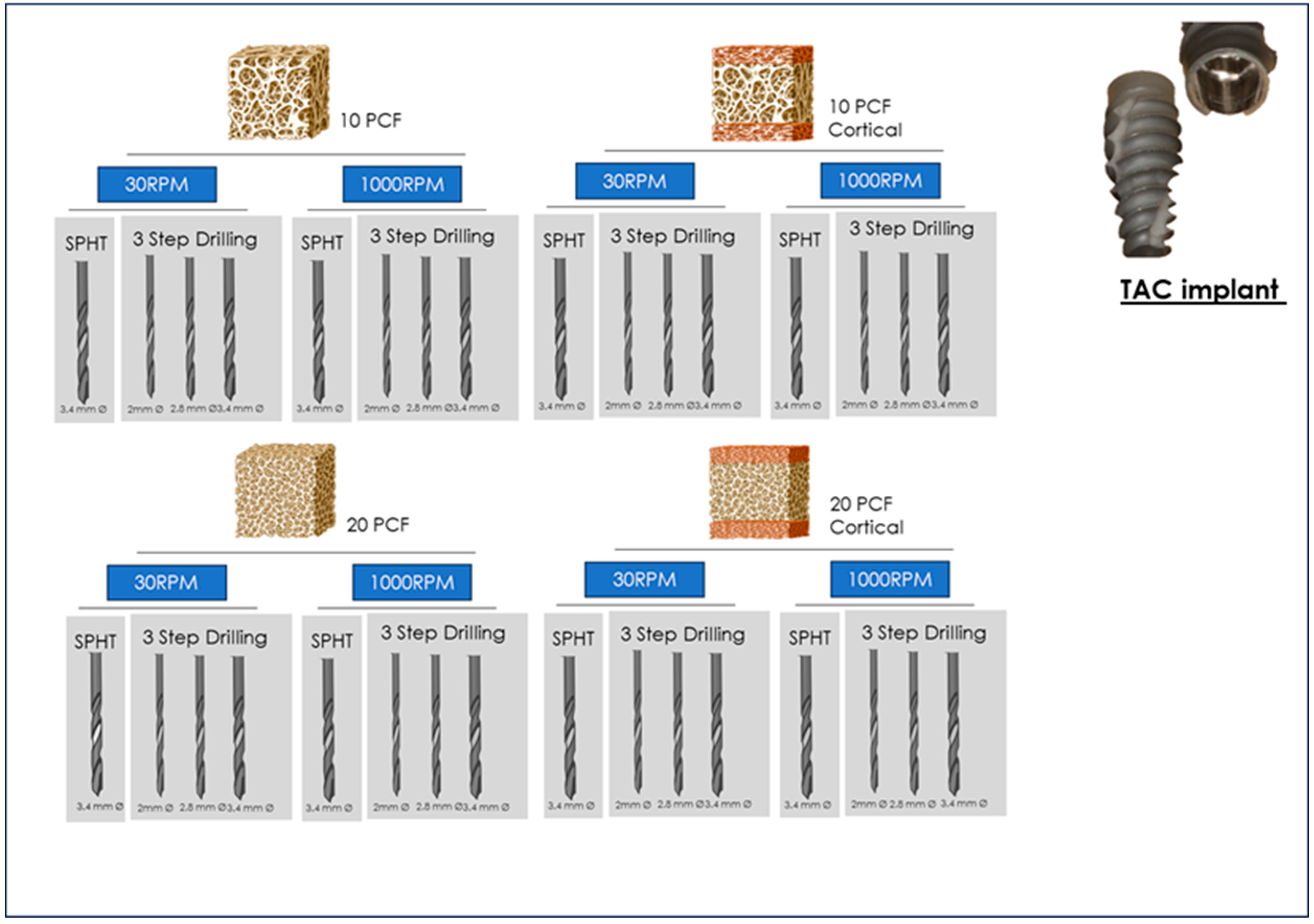
The experiment consisted in a total of 10 samples for each tested condition in critical and supercritical polyurethane bone substitute that differed in density and presence/absence of cortical layer (SawBones H, Pacific Research Laboratories Inc, Vashon, WA, USA). The study groups were consequently planned according to the substitute characteristics (Figure 1), consisting of the following: 10 pound-per-cubic-feet PCF with cortical layer, 10 pound-per-cubic-feet PCF without cortical layer, 20 pound-per-cubic-feet PCF with cortical layer, and 10 pound-per-cubic-feet PCF without cortical layer (Figure 1). Two different implant profiles were tested: TAC vs. NT implants according to Single-Drill Primary Healing Technique (SPHT) at low rotational speed (30 rpm), Single-Drill Primary Healing Technique (SPHT) at standard rotational speed (1000 rpm), progressive three step drilling procedure at low rotational speed (30 rpm), and progressive three-step drilling procedure at standard rotational speed (1000 rpm).

Figure 1.
Summary of the study design of the present investigation.
2.2. Dental Implants
A total of two different implant groups were determined
- -
- Implant A: TAC conical implant (AON Implant, Grisignano di Zocco, Vicenza, Italy)
- -
- Implant B: NT (Nanotite) (Biomet 3i, Biomet Palm Beach Gardens, FL, USA)
The TAC implant has a conical profile and a smooth thread design. The apical portion is rounded with V-shaped threads. The surface grooves are extended from the apex to two thirds of the implant. The surface treatment was double acid-etched. The implant-abutment connection is a Cone Morse connection. The Nanotite implant is characterized by a tapered microgeometry and V-shaped threads. The apical potion is characterized by V-shape apex and apex grooves. The implant–abutment connection has an external hexagonal design (Figure 2).
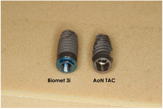
Figure 2.
Detail of the medical devices tested on polyurethane blocks.
2.3. Drilling Osteotomy
Two different drilling procedures were tested in the present investigation. The drilling procedures observed were as follows: (1) Single-Drill Primary Healing Technique (SPHT) (Figure 3), and (2) Three-Step Technique (Figure 4). Both of these techniques were evaluated at low speed (30 rpm) and standard speed (1000 rpm). The single-drill primary healing technique is a technique proposed to reduce the osteotomy sequence and duration of the procedure (Figure 5). This procedure seemed to be able to reduce the duration of the surgical procedure with higher patient comfort; specially designed to operate at low speed without irrigation, the drill offers maximum control. Torque values generated via the instrument guide surgical workflow, assist in bone evaluation, and provide early prediction of implant stability. Moreover, this simplified drilling sequence consists in the use of the pilot drill followed by the final shape of the osteotomy drill. Preparation after the pilot drill (diameter: 2 mm), which establishes the length of the preparation as well as position and direction, is followed by the final drill which produces the osteotomy site at low speed (diameter: 3.4 mm). The aim this technique was to prepare the bone site corresponding exactly to the size and shape of the implant to obtain a conical coupling without compressions that would damage the viability of the cells. The three-step osteotomy technique is purposed to produce, after the use of the pilot drill (diameter: 2 mm), a progressive preparation of the bone in order to adapt the donor site to the final diameter and length of the size chosen, achieving the optimal positioning torque of the fixture. The sequence was pilot drill (diameter: 2 mm), 2.8 mm diameter drill, 3.4 diameter final drill for both implant groups.
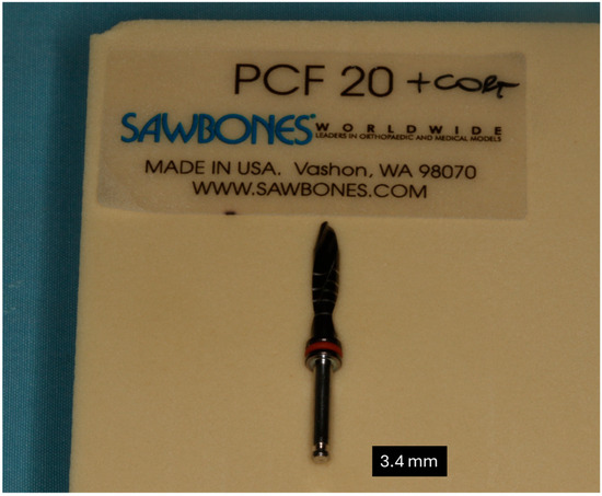
Figure 3.
Detail of the drill used for SPHT protocol.
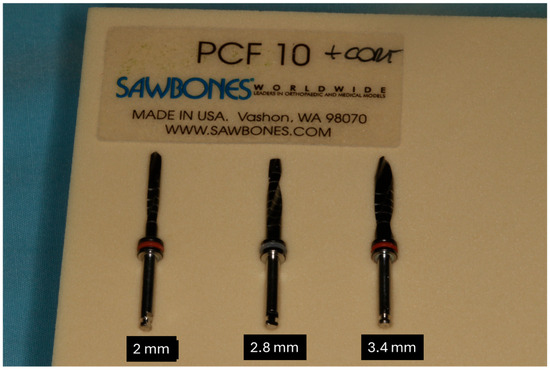
Figure 4.
Detail of the drill used for 3-step drilling protocol.

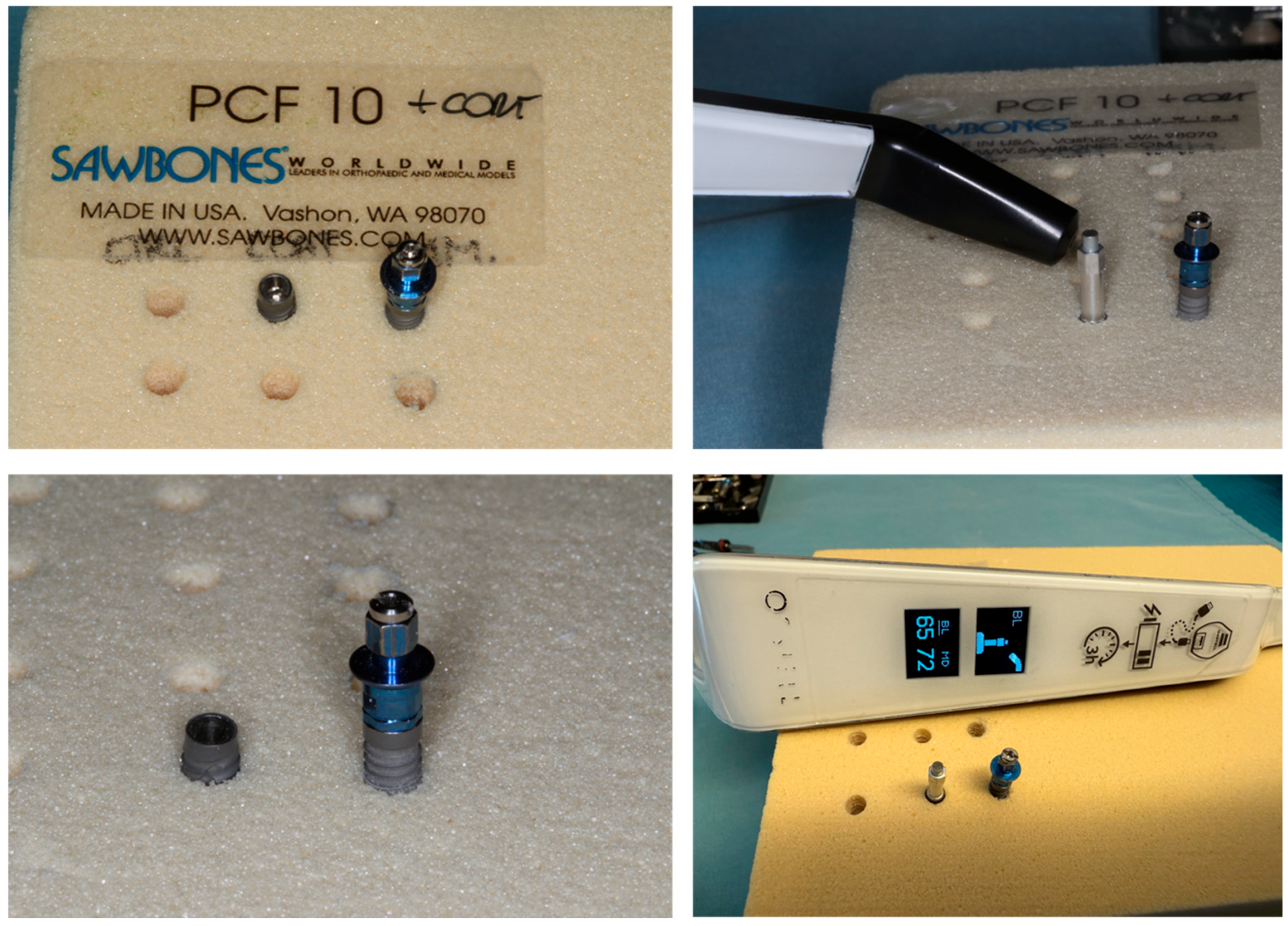
Figure 5.
Detail of the preparation performed on polyurethane blocks.
2.4. Insertion Torque and Removal Measurements
The experimental implants were positioned recording the IT insertion torque, while the tensile and removal resistance was performed by dynamometric analysis of the removal of the implant from the block.
IT was evaluated using an OMEGA digital dynamometer (Arthur-Sauvé, St-Eustache, QC, Canada) coupled with the implant insertion driver as per the implant system protocol.
2.5. Resonance Frequency Analysis (RFA)
The RFA (Osstell, Columbia, MD, USA) is an electromechanical assessment that is performed by an electronic device that measures the micromovement of the implant for a total of 16 times. The RFA device can self-eliminate the non-compliant pulse, offering a reliable and reproducible measurement of the implant micro-mobility. For TAC implants, the smartpeg no. 78 was used according to the manufacturing indications, while for the NT system, smartpeg no. 1 for external hexagon systems was applied (Figure 5).
The measurements are classified according to the implant stability quotient score (ISQ), in the range of 1–100:
- -
- Good stability: >70 ISQ;
- -
- Medium Stability: 60–69 ISQ;
- -
- Low Stability: <60 ISQ.
2.6. Statistical Analysis
Descriptive statistics will be provided in summary tables by group based on the type of measure of the summarized result. The general descriptive statistics for continuous outcome measures included (number of observed values) mean with 95%CI, standard deviation, median, minimum, and maximum values. The hypothesis will be tested with a multivariate analysis of variance (MANOVA) with basal values of IT, RT, and RFA. The implant design, drilling speed, osteotomy technique, the bone density and the cortical component were considered independent variables, and the insertion torque, removal torque, and ISQ were the dependent variables. The groups will be compared at the 5% significance level. Data collection and statistical analysis will be performed using StatPlus 6 software (AnalystSoft Inc., Walnut, CA, USA). The sample size computing was performed considering an effect size of 0.032, alfa error: 0.05, power 0.80 for a total of 320 sites.
3. Results
- TAC Implant Group
3.1. Insertion Torque
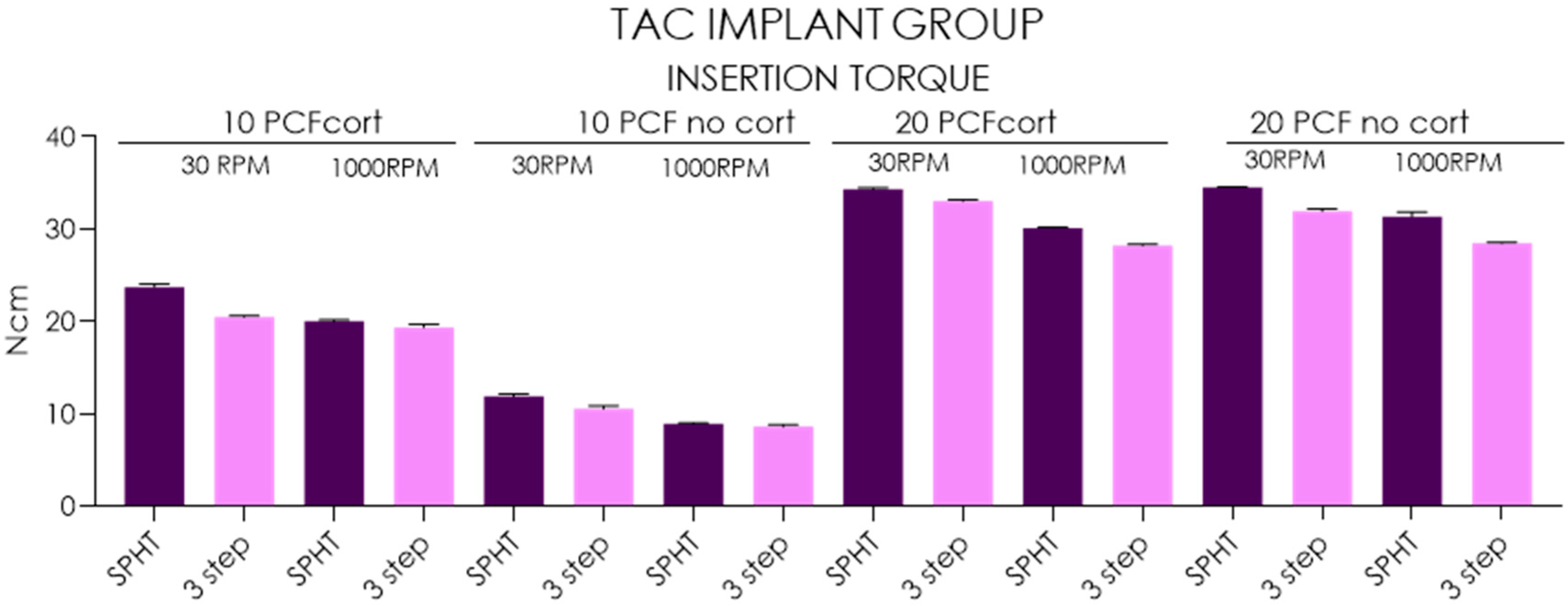
The mean insertion torque of SPHT ranged from 8.93 ± 0.08 Ncm (95%CI: 8.87–8.99) recorded in 10 PCF polyurethane blocks with no cortical to 23.3 ± 0.3 Ncm (95%CI: 23.5–24), while the 3-step drilling ranged from 8.61 ± 0.23 Ncm (95%CI: 8.44–8.78) and 20.5 ± 0.15 Ncm (95%CI: 20.4–20.6) in the respective conditions. In 20 PCF tests, SPHT ranged from 30.1 ± 0.08 Ncm (95%CI: 30–30.2) recorded in no cortical blocks to 34.5 ± 0.08 Ncm (95%CI: 34.4–34.6), while the 3-step drilling ranged from 28.2 ± 5 Ncm (95%CI: 28.1–28.3) in no cortical blocks to 33.0 ±0.17 Ncm (95%CI: 28.1–28.3) in the respective conditions. In 10 PCF bone substitutes, the insertion torque percentage increased from 49.79% to 55.39% in presence of the cortical layer where the SPHT performed at low speed recorded the higher performance in terms of implant torque in all conditions tested (p < 0.05). Moreover, the SPHT vs. 3-step drilling produced 23.11–33.25% increase of insertion torque in 10 PCF with no layer and 6.21–18.5% in 10 PCF with cortical layer (p < 0.05). Testing 20 PCF polyurethane block, the insertion torque percentage increased from 0.58% to 3.99% in presence of the cortical layer where the SPHT performing at low speed recorded the higher performance in terms of implant torque (p < 0.05). Moreover, the low-speed drilling produced a 13.95–17.02% increase of insertion torque in 20 PCF with no layer and 10.22–11.92% in 20 PCF with cortical layer (p < 0.05) (Table 1, Figure 6).

Table 1.
Summary of the descriptive statistics concerning insertion torque.

Figure 6.
Chart of the insertion torque measured in different conditions and polyurethane densities.
3.2. Removal Torque
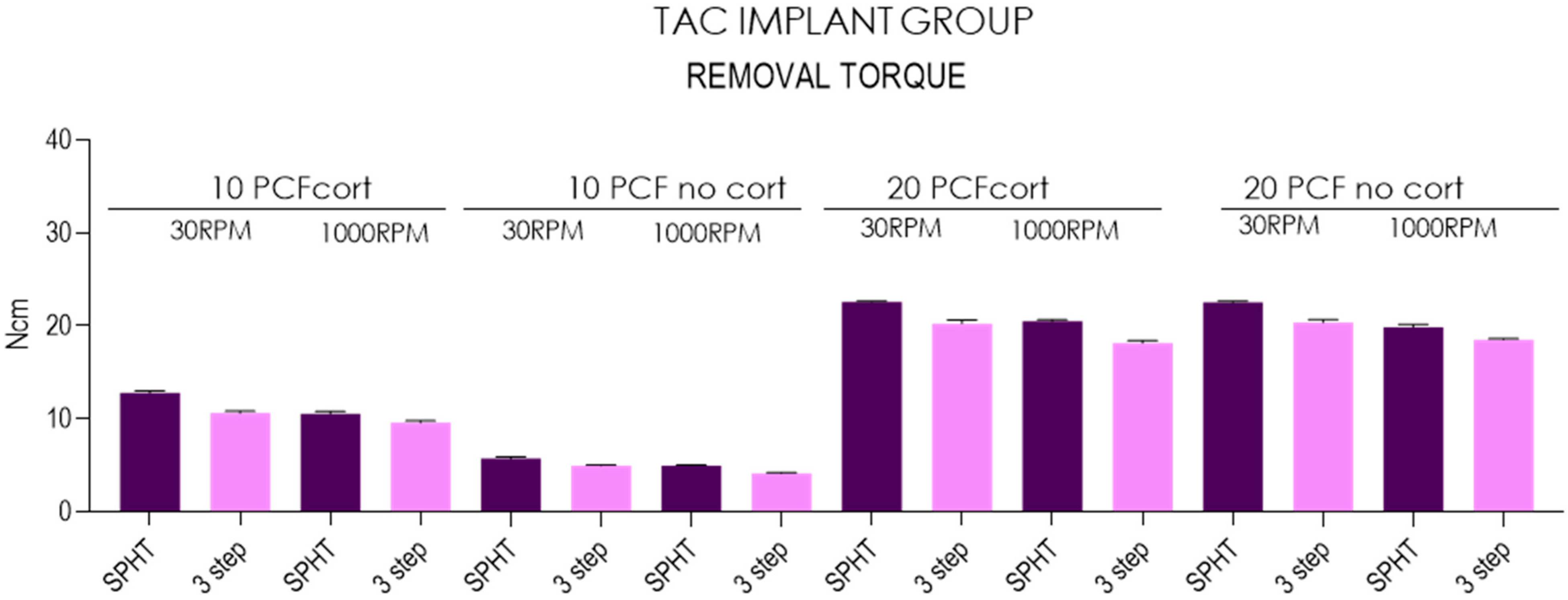
The mean insertion torque of SPHT technique ranged from 4.96 ± 0.05 Ncm (95%CI: 4.92–5) recorded in 10 PCF polyurethane blocks with no cortical to 12.8 ± 0.2 Ncm (95%CI: 12.6–12.9), while the 3-step drilling technique ranged from 4.13 ± 0.08 Ncm (95%CI: 4.07–4.19) to 10.6 ±0.23 Ncm (95%CI: 10.6–10.8) in the respective conditions. In 20 PCF tests, SPHT technique ranged from 19.9 ± 0.30 Ncm (95%CI: 19.6–20.1) recorded in no cortical blocks to 22.6 ± 0.08 Ncm (95%CI: 22.5–22.6), while the standard drilling technique ranged from 20.4 ± 0.29 Ncm (95%CI: 20.1–20.6) to 18.2 ± 0.25 Ncm (95%CI: 18–18.3) in the respective conditions. In 10 PCF bone substitutes, the removal torque percentage increased from 53.21% to 56.93% in presence of the cortical layer, where SPHT performing at 30 RPM rotational speed recorded the higher performance in terms of removal torque in all conditions tested (p < 0.05). Moreover, the 30 RPM vs. 1000 RPM speed produced an increase of removal torque in the range of 14.91–19.85% in 10 PCF with no layer and 10.53–20.75% in 10 PCF with cortical layer (p < 0.05). Testing 20 PCF bone substitutes, the removal torque percentage increased from 0.44% to 2.93% in presence of the cortical layer, where the SPHT at 30 RPM recorded the higher performance in terms of implant torque (p < 0.05). Moreover, the 30 RPM vs. 1000 RPM drilling produced a 10.27–13.06% increase in insertion torque in 20 PCF with no layer and 11.24–11.53% in 20 PCF with cortical layer (p < 0.05)) (Table 2, Figure 7).
Table 2.
Summary of the descriptive statistics concerning removal torque.

Figure 7.
Chart of the removal torque measured in different conditions and polyurethane densities.
3.3. Resonance Frequency Analysis
The mean RFA of SPHT ranged from 53.2 ± 1.84 ISQ (95%CI: 51.8–54.5) recorded in 10 PCF polyurethane blocks with no cortical to 63.8 ± 0.48 ISQ (95%CI: 63.4–64.1), while the 3-step drilling technique ranged from 48.4 ± 0.78 ISQ (95%CI: 47.8–48.9) to 61.4 ± 0.62 Ncm (95%CI: 60.9–61.8) in the respective conditions. In 20 PCF tests, SPHT ranged from 65.5 ±0.36 ISQ (95%CI: 65.2–65.7) recorded in no cortical blocks to 76.1 ± 0.76 Ncm (95%CI: 75.5–76.6), while the 3-step drilling technique ranged from 64.9 ±0.33 Ncm (95%CI: 64.6 -65.1) to 72.9 ± 0.65 Ncm (95%CI: 72.4–73.4) in the respective conditions. In 10 PCF bone substitutes, the ISQ percentage increased from 11.29% to 15.38% in presence of the cortical layer, where the SPHT performing at low-speed Primary Healing recorded the higher performance in terms of ISQ in all conditions tested (p < 0.05). Moreover, the 30 RPM vs. 1000 RPM drilling produced an increase of ISQ in the range of 6.39–10.74% in 10 PCF with no layer and 3.90–6.11% in 10 PCF with cortical layer (p < 0.05). Testing 20 PCF bone substitutes, the ISQ increased from 4.28% to 10.38% in presence of the cortical layer, where the SPHT performing at low speed recorded the higher performance in terms of implant torque (p < 0.05). Moreover, the 30 RPM vs. 1000 RPM drilling produced an increase in ISQ range between 0.92–4.12% in 20 PCF with no layer and 6.58–7.52% in 20 PCF with cortical layer (p < 0.05) (Table 3, Figure 8).
Table 3.
Summary of the descriptive statistics concerning RFA.
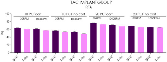
Figure 8.
Chart of the RFA measured in different conditions and polyurethane densities.
- NT Implant Group
3.4. Insertion Torque
The mean insertion torque of SPHT technique ranged from 7.14 ± 0.19 Ncm (95%CI: 7–7.28) recorded in 10 PCF polyurethane blocks with no cortical to 17.4 ±0.149 Ncm (95%CI: 17.3–17.5), while the 3-step drilling technique ranged from 4.5 ± 0.236 Ncm (95%CI: 4.33–4.67) and 16 ± 0.236 Ncm (95%CI: 15.8–16.1) in the respective conditions. In 20 PCF tests, SPHT technique ranged from 27.1 ± 0.399 Ncm (95%CI: 26.8–27.4) recorded in no cortical blocks to 40.9 ± 0.117 Ncm (95%CI: 40.9- 41), while the 3-step drilling technique ranged from 35.2 ± 0.125 Ncm (95%CI: 35.1–35.3) and 4.5 ± 0.236 Ncm (95%CI:4.33–4.67) in the respective conditions. In 10 PCF bone substitutes, the insertion torque percentage increased from 49.56% to 69.59% in presence of the cortical layer, where the SPHT at low-speed ROP recorded the higher performance in terms of implant torque in all conditions tested (p < 0.05). Moreover, the 30 RPM vs. 1000 RPM drilling produced 29.27–78.2% increase in insertion torque in 10 PCF with no layer and 7.43–8.65% in 10 PCF with cortical layer (p < 0.05). Testing 20 PCF bone substitutes, the insertion torque percentage increased from 9.66% to 26.76% in presence of the cortical layer, where the SPHT at low-speed ROP recorded the higher performance in terms of implant torque (p < 0.05). Moreover, the 30 RPM vs. 1000 RPM drilling produced a 26.19–35.31% increase in insertion torque in 20 PCF with no layer and 10.54–14.65% in 20 PCF with cortical layer (p < 0.05) (Table 4; Figure 9).
Table 4.
Summary of the descriptive statistics concerning insertion torque.
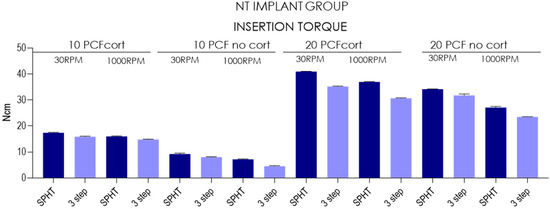
Figure 9.
Chart of the insertion torque measured in different conditions and polyurethane densities.
3.5. Removal Torque
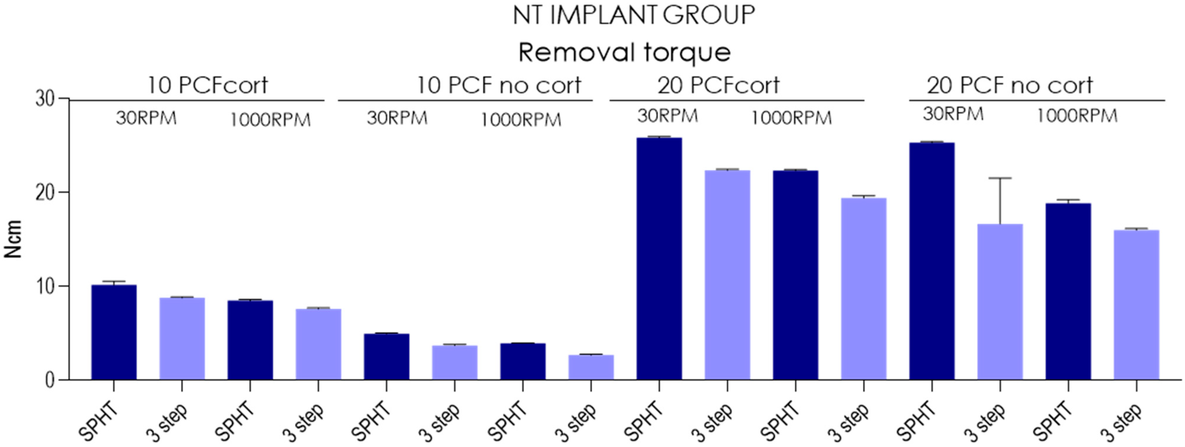
The mean insertion torque of SPHT technique ranged from 4.98 ±0.0789 Ncm (95%CI: 4.92–5.04) recorded in 10 PCF polyurethane blocks with no cortical to 10.2 ± 0.38 Ncm (95%CI: 9.93–10.5), while the 3-step drilling ranged from 2.72 ± 0.0919 Ncm (95%CI: 2.65–2.79) to 8.81 ± 0.0994 Ncm (95%CI: 8.74- 8.88) in the respective conditions. In 20 PCF tests, SPHT technique ranged from 18.9 ± 0.384 Ncm (95%CI: 18.6–19.2) recorded in no cortical blocks to 25.9 ± 0.117 Ncm (95%CI: 25.8–25.9), while the standard drilling technique ranged from 16 ± 0.175 Ncm (95%CI: 15.9–16.1) to 22.4 ± 0.116 Ncm (95%CI: 22.3–22.5) in the respective conditions. In 10 PCF bone substitutes, the removal torque percentage increased from 51.18% to 57.55% in presence of the cortical layer, where the SPHT at low speed recorded the higher performance in terms of removal torque in all conditions tested (p < 0.05). Moreover, the 30 RPM vs. 1000 RPM drilling produced an increase in removal torque in the range of 10 PCF 25.75–37.5% with no layer and 15.46–19.71% in 10 PCF with cortical layer (p < 0.05). Testing 20 PCF bone substitutes, the removal torque percentage increased from 2.32% to 25.45% in presence of the cortical layer, where the SPHT at low-speed ROP recorded the higher performance in terms of implant torque (p < 0.05). Moreover, the 30 RPM vs. 1000 RPM drilling produced a 4.37–33.86% increase in insertion torque in 20 PCF with no layer and 15.46–15.6% in 20 PCF with cortical layer (p < 0.05) (Table 5; Figure 10).
Table 5.
Summary of the descriptive statistics concerning removal torque.
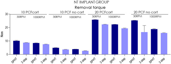
Figure 10.
Chart of the removal torque measured in different conditions and polyurethane densities.
3.6. Resonance Frequency Analysis
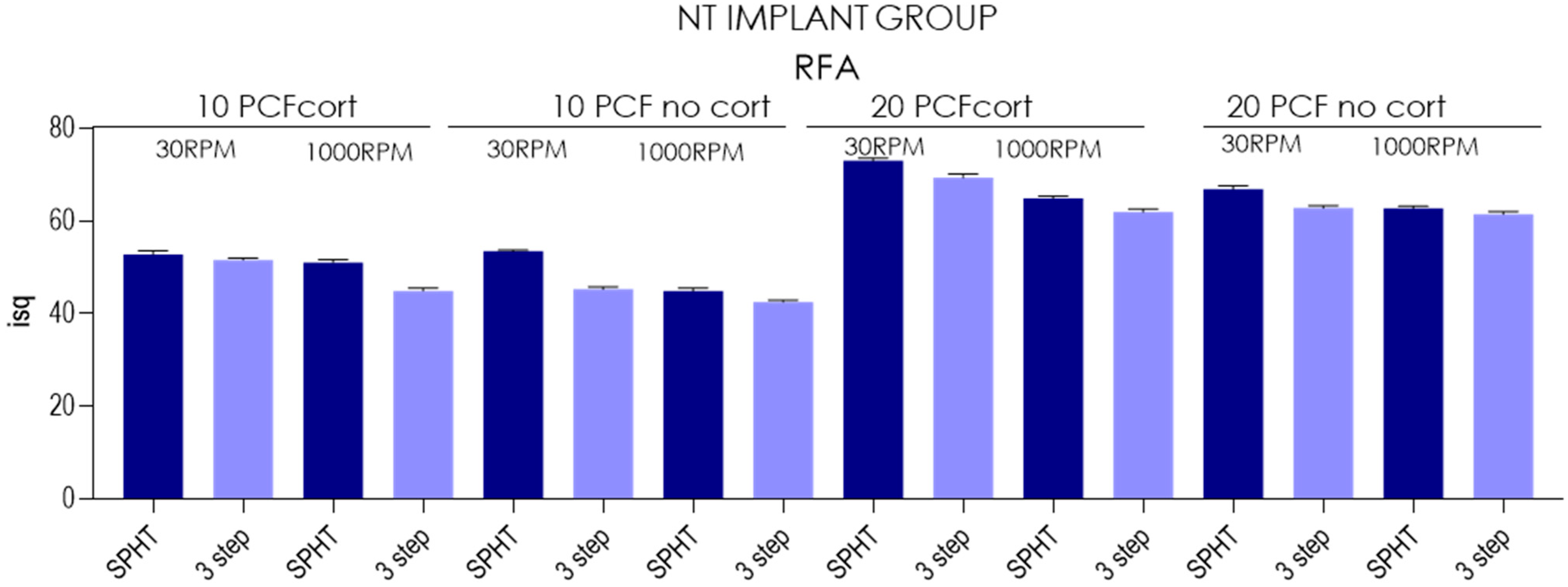
The mean RFA of SPHT ranged from 44.9± 0.669 isq (95%CI: 44.4- 45.3) recorded in 10 PCF polyurethane blocks with no cortical to 53.4 ±0.316 isq (95%CI: 53.2–53.6), while the 3-step technique ranged from 44.9 ± 0.669 isq (95%CI: 44.4–45.3) to 51.6 ±0.438 Ncm (95%CI: 51.2–51.9) in the respective conditions. In 20 PCF tests, SPHT technique ranged from 62.7± 0.483 (95%CI: 62.4–63) recorded in no cortical blocks to 73 ±0.643 Ncm (95%CI: 72.5–73.4), while the 3-step drill technique ranged from 61.4 ± 0.615 Ncm (95%CI: 61–61.8) to 69.3 ±0.856 Ncm (95%CI: 68.7–69.9) in the respective conditions.
In 10 PCF bone substitutes, the ISQ percentage increased from 1.14% to 12.21% in presence of the cortical layer, where the SPHT performing at low-speed ROP recorded the higher performance in terms of ISQ in all conditions tested (p < 0.05). Moreover, the 30 RPM vs. 1000 RPM produced an increase in ISQ in the range of 6.58–18.93% in 10 PCF with no layer and 3.52–14.9% in 10 PCF with cortical layer (p < 0.05). Testing 20 PCF bone substitutes, the ISQ increased from 0.81% to 9.38% in presence of the cortical layer, where the SPHT at low-speed ROP recorded the higher performance in terms of implant torque (p < 0.05). Moreover, the 30 RPM vs. 1000 RPM speed drilling produced an increase in ISQ in the range of 2.28–6.69% in 20 PCF with no layer and 11.95–12.65% in 20 PCF with cortical layer (p < 0.05) (Table 6; Figure 11).
Table 6.
Summary of the descriptive statistics concerning RFA.

Figure 11.
Chart of the RFA measured in different conditions and polyurethane densities.
4. Discussion
One of the most important features of bone tissue is its healing capability, with no scar formation and complete reconstitution of the architecture, after a trauma. Direct or primary healing of bone, without a formation of fibrocartilage, after a fracture needs a precise reduction in the fracture ends, with a stable fixation and no micromovements, due probably to the press fit, good vascularization, and no gaps [9,10]. This direct type of healing occurs by direct remodeling of lamellar bone, Haversian canals, and blood vessels [12]. Professor Robert Schenk and his coworkers, in a series of experimental and clinical studies found that, using the Primary or Direct bone healing technique or concept, an orthopedic prosthesis was strongly embedded in the bone tissue, with newly formed bone in direct, close, and tight contact with the metal surface [13,14,15,16,17]. In the early 1990s, our laboratory had the opportunity to perform some animal experiment studies and some human clinical and histological evaluations on retrieved implants that were inserted according to the primary bone healing concept (PHI, San Vittore Olona, Milano, Italy). In all these animal and human specimens, a very high bone-to-implant contact percentage was always found, and the newly formed mineralized bone was always in close and direct contact with the titanium surface [6,18,19,20].
There are three types of shape-based endosseous implant bodies: cylindrical, screw-shaped, and combined. Cylindrical implants are distinguished by the fact that their surfaces are parallel and do not narrow towards the end, unlike conical implants. Both these shapes can have smooth or grooved outer surfaces [21]. Implants with a smooth surface must achieve stability in the bone tissue mainly through a specific coating or surface treatment, as they lack visible anchoring elements. Usually, the surface is roughened or provided with macroscopic anchoring structures through a specific coating or treatment [21]. Cylindrical implants are usually placed by pressure or placed at a previously prepared bone site, offering significant advantages, especially in situations where access is difficult. Threaded implants, on the other hand, are placed at a bone site with a slightly smaller preparation [22]. The tapered apical portion allowed one to obtain good primary stability with high torques without histological evidence of pressure necrosis (from 65 to 100 Ncm) and good secondary stability with a mean BIC of 56.34% [23]. The geometry of the coils can also affect bone healing. The first evidence of the present investigation was that the conical implant primary stability is significantly affected by the thread’s morphology and capability to create a stable interface with the peripheral bone tissue. In fact, the insertion torque, removal torque, and RFA values were higher in all conditions tested compared to NT implants (p < 0.05). The most advanced microgeometry shape of implants, conical TAC implants, favored implant stabilization as seen in other studies of our group. They stabilize in the polyurethane progressively until they reach maximum torque near the engagement of the platform with the polyurethane.
A recent histological and biomechanical study on an animal model at 2 months compared three different types of implants for the morphology of the coils, “V” coils, rectangular coils, and long coils with healing chambers, finding on histomorphometrical analysis a greater amount of newly formed interthread bone in the third group, while the BIC and torque removal value were unchanged. This suggests that creating healing chambers at the level of implant macrogeometry can promote better bone response than conventional designs [24,25,26]. A design with a self-threading in the apical portions can help in obtaining better primary stability even in areas with poor-quality bone or in the presence of buccal defects. By modifying the implant morphology, it is therefore possible to increase primary stability in the apical areas and create compartments for healing, i.e., to give adequate space to the clot in order to promote bone neoformation and try to compensate for the physiological post-extraction alveolar resorption. The second focus could be oriented to the drilling procedure and the risk of overheating. The present study tested both techniques at high and low rotational speed in low-density bone. The limit of the present study model is that it could mask the frictional over-stress that a high-speed simultaneous preparation could produce on bone tissue, which, hypothetically, could be observed in >D3 density [27]. Another issue could be determined by the control difficulties of the osteotomy direction that could create problems regarding the correct final position of the implant. For this purpose, the use of surgical guides could ensure the respect of the planned prosthetic axis, limiting any bias connected to the augmented frictional forces on the drill [27]. In addition, the reduced sample size could represent another significant limit that should be taken into account for the validation of the study outcomes. The osteotomy at very low rpm avoids the risk of overheating (but with high milling torque), no irrigation and no cooling is needed, and the introduction of variables is avoided with the use of exogenous liquids; at the same time, there is the very useful possibility of recovering bone chips to be reused during surgery [28]. According to several studies by Schenk et al., an osteotomy must be a fracture that leaves intact the architecture of the bone surface and osteocytes, which remain viable [19,20,28,29,30,31]. The primary bone healing presents a complex event that could be realized according to different forms: by direct contact or by “healing gap”. If the gap between fragments is <0.01 mm and the interfragmentary stresses are <2%, the fracture joins by “direct contact” through a process of intramembranous ossification [32]. Under these conditions, perforating wedges form at the ends of the osteons closest to the fracture site [14,15,33]. Recent studies seem to suggest that the increase in depth and drilling speed seems to affect the bone cells’ viability and potentially interferes with the osseointegration process [34,35]. On the other hand, no difference in BIC and BAFO has been reported comparing simultaneous drilling technique vs. standard protocol [34,35]. A recent study by Jang et al. suggested that 50 rpm with no irrigation drilling seems to produce a stable thermal generation with no evidence of overheating on D1 bone [36]. Similar evidence has been detected by Gil et al. comparing both techniques with a 400 rpm drilling speed on a 4.2 diameter implant [37]. On humans, Tabassum et al. reported that no difference in marginal bone resorption was detected in implants positioned after 12 months of follow-up [38,39]. The drill technique tested in the present investigation aimed to preserve the osteogenic cells’ viability, decreasing the osteotomy trauma and the tissue overheating due to the cutting flutes’ design efficiency and the reduced drilling speed [10].
The most appropriate speed to increase the fixity parameters seems to be the low one (30 rpm) in all situations. In the highest consistency with cortical (PCF + cort), the conical implants 3i reach the highest torque compared to all the others, but the ISQ values are always to the advantage of the TACs in all the situations proposed. In the 10PCF consistency block, the same results are repeated as in the 20PCF block with lower but proportionate values. There is also a progressive increase in insertion torque starting from the 10PCF cortical-free block for the high-speed transition to 3 drills, then slightly improving for implants by switching to low speed, improving again by switching to 1 low-speed drill, and following this trend by increasing the consistency of polyurethane by adding cortical, and then moving to the 20PCF cortical-free consistency to finally reach the maximum for the 20PCF consistency with cortical. At the level of RFA (Implant Resonance Frequency Analysis) the ISQ (Implant Stability Quotient) values, it is noted that the maximum parameter is obtained when the 20PCF block with a thickness of 1 mm of cortical is present and the best value is obtained by the CT implant inserted at low speed with 1 single pass (76/76) followed by the 3i (73/74) always at a single pass at low speed. The main influence of a high cortical/medullary ratio is an increase in insertion torque [40]; this leads to higher temperatures during the insertion phase, as demonstrated by Markovic et al. [41] and confirmed, in the orthopedic field, by Wikenheiser et al. [42]. Despite this, a torque value between 30 and 40 Ncm is considered safe in terms of thermal effect on bone [43]. The torque value depends on the following parameters: bone quantity and quality, implant geometry [43], and osteotomy diameter: the execution of undersized osteotomies is associated with a higher bone heating at the time of implant insertion than normal-sized osteotomies [44]. In this research, the insertion torque value was not significantly different between narrow and regular implants, although there was a trend whereby the values of the “narrow” group are lower than those of the “regular” group; this confirms the results obtained by Barikani et al. [45].
5. Conclusions
The conical macrogeometric shape of the new-generation implants (TAC) favors the stabilization of the implants that fit into the polyurethane in a progressive manner until they reach the maximum T-IN and ISQ near the platform. The best results are with a single drill at low speed for all situations.
The NT conical macrogeometric shape is less performing both in insertion and removal torque and in the RFA (ISQ). Considering the low density of polyurethane in cortical-free 10PCF blocks, the T-IN was not elevated for any implant, but the worsening influence is given not only by the polyurethane density, but also and above all by the 3 passes of cutters and at high speed. The insertion torque values in the non-cortical block are lowered for all implants, which suggests that the presence of at least 1 mm of cortical is important to help increase the investigated values.
Author Contributions
Conceptualization, A.P., M.T., L.C. and N.D.P.; methodology, L.C.; investigation, L.C., M.T., A.P., A.C., G.M., N.D.P. and T.R.; data curation, L.C., A.P. and M.T.; writing—original draft preparation, M.T., N.D.P., A.P., L.C. and A.C.; writing—review and editing, M.T., N.D.P., A.P., G.M. and T.R. All authors have read and agreed to the published version of the manuscript.
Funding
This research received no external funding.
Institutional Review Board Statement
Not applicable.
Informed Consent Statement
Not applicable.
Data Availability Statement
All experimental data to support the findings of this study are available contacting the corresponding author upon request.
Conflicts of Interest
The authors declare no conflicts of interest.
References
- Anitua, E.A. Enhancement of Osseointegration by Generating a Dynamic Implant Surface. J. Oral Implantol. 2006, 32, 72–76. [Google Scholar] [CrossRef]
- Albrektsson, T.; Wennerberg, A. On Osseointegration in Relation to Implant Surfaces. Clin. Implant Dent. Relat. Res. 2019, 21 (Suppl. S1), 4–7. [Google Scholar] [CrossRef]
- Möhlhenrich, S.C.; Kniha, K.; Heussen, N.; Hölzle, F.; Modabber, A. Effects on Primary Stability of Three Different Techniques for Implant Site Preparation in Synthetic Bone Models of Different Densities. Br. J. Oral Maxillofac. Surg. 2016, 54, 980–986. [Google Scholar] [CrossRef]
- Davies, J.E. Understanding Peri-Implant Endosseous Healing. J. Dent. Educ. 2003, 67, 932–949. [Google Scholar] [CrossRef]
- Cipollina, A.; Ceddia, M.; Di Pietro, N.; Inchingolo, F.; Tumedei, M.; Romasco, T.; Piattelli, A.; Specchiulli, A.; Trentadue, B. Finite Element Analysis (FEA) of a Premaxillary Device: A New Type of Subperiosteal Implant to Treat Severe Atrophy of the Maxilla. Biomimetics 2023, 8, 336. [Google Scholar] [CrossRef]
- Piattelli, A.; Corigliano, M.; Scarano, A. Microscopical Observations of the Osseous Responses in Early Loaded Human Titanium Implants: A Report of Two Cases. Biomaterials 1996, 17, 1333–1337. [Google Scholar] [CrossRef]
- Al-Nawas, B.; Groetz, K.A.; Goetz, H.; Duschner, H.; Wagner, W. Comparative Histomorphometry and Resonance Frequency Analysis of Implants with Moderately Rough Surfaces in a Loaded Animal Model. Clin. Oral Implant. Res. 2008, 19, 1–8. [Google Scholar] [CrossRef]
- Friberg, B.; Sennerby, L.; Linden, B.; Gröndahl, K.; Lekholm, U. Stability Measurements of One-Stage Brånemark Implants during Healing in Mandibles: A Clinical Resonance Frequency Analysis Study. Int. J. Oral Maxillofac. Surg. 1999, 28, 266–272. [Google Scholar] [CrossRef]
- Velikov, S.; Susin, C.; Heuberger, P.; Irastorza-Landa, A. A New Site Preparation Protocol That Supports Bone Quality Evaluation and Provides Predictable Implant Insertion Torque. J. Clin. Med. 2020, 9, 494. [Google Scholar] [CrossRef]
- Chen, C.-H.; Coyac, B.R.; Arioka, M.; Leahy, B.; Tulu, U.S.; Aghvami, M.; Holst, S.; Hoffmann, W.; Quarry, A.; Bahat, O. A Novel Osteotomy Preparation Technique to Preserve Implant Site Viability and Enhance Osteogenesis. J. Clin. Med. 2019, 8, 170. [Google Scholar] [CrossRef]
- Bernabeu-Mira, J.C.; Soto-Peñaloza, D.; Peñarrocha-Diago, M.; Camacho-Alonso, F.; Rivas-Ballester, R.; Peñarrocha-Oltra, D. Low-Speed Drilling without Irrigation versus Conventional Drilling for Dental Implant Osteotomy Preparation: A Systematic Review. Clin. Oral Investig. 2021, 25, 4251–4267. [Google Scholar] [CrossRef]
- Marsell, R.; Einhorn, T.A. The Biology of Fracture Healing. Injury 2011, 42, 551–555. [Google Scholar] [CrossRef]
- Willenegger, H.; Perren, S.M.; Schenk, R. Primary and Secondary Healing of Bone Fractures. Chir. Z. Alle Geb. Oper. Medizen 1971, 42, 241–252. [Google Scholar]
- Schenk, R.K.; Willenegger, H.R. Histology of Primary Bone Healing: Modifications and Limits of Recovery of Gaps in Relation to Extent of the Defect (Author’s Transl). Unfallheilkunde 1977, 80, 155–160. [Google Scholar]
- Schenk, R.K. Histology of Primary Bone Healing. Fortschr. Kiefer. Gesichtschir. 1975, 19, 8–12. [Google Scholar]
- Schenk, R.; Willenegger, H. On the Histological Picture of So-Called Primary Healing of Pressure Osteosynthesis in Experimental Osteotomies in the Dog. Experientia 1963, 19, 593–595. [Google Scholar] [CrossRef]
- Schenk, R.K.; Wehrli, U. Reaction of the Bone to a Cement-Free SL Femur Revision Prosthesis. Histologic Findings in an Autopsy Specimen 5 1/2 Months after Surgery. Orthopade 1989, 18, 454–462. [Google Scholar]
- Scarano, A.; Iezzi, G.; Petrone, G.; Marinho, V.C.; Corigliano, M.; Piattelli, A. Immediate Postextraction Implants: A Histologic and Histometric Analysis in Monkeys. J. Oral Implantol. 2000, 26, 163–169. [Google Scholar] [CrossRef]
- Piattelli, A.; Corigliano, M.; Scarano, A.; Costigliola, G.; Paolantonio, M. Immediate Loading of Titanium Plasma-Sprayed Implants: An Histologic Analysis in Monkeys. J. Periodontol. 1998, 69, 321–327. [Google Scholar] [CrossRef]
- Albertini, M.; Herrero-Climent, F.; Díaz-Castro, C.M.; Nart, J.; Fernández-Palacín, A.; Ríos-Santos, J.V.; Herrero-Climent, M. A Radiographic and Clinical Comparison of Immediate vs. Early Loading (4 Weeks) of Implants with a New Thermo-Chemically Treated Surface: A Randomized Clinical Trial. Int. J. Environ. Res. Public Health 2021, 18, 1223. [Google Scholar] [CrossRef]
- Misch, K.E. Implantologia Contemporanea; Elsevier: Amsterdam, The Netherlands, 2015; ISBN 978-88-214-3220-0. [Google Scholar]
- Le Guéhennec, L.; Soueidan, A.; Layrolle, P.; Amouriq, Y. Surface Treatments of Titanium Dental Implants for Rapid Osseointegration. Dent. Mater. 2007, 23, 844–854. [Google Scholar] [CrossRef]
- Nevins, M.; Chu, S.J.; Jang, W.; Kim, D.M. Evaluation of an Innovative Hybrid Macrogeometry Dental Implant in Immediate Extraction Sockets: A Histomorphometric Pilot Study in Foxhound Dogs. Int. J. Periodontics Restor. Dent. 2019, 39, 29–37. [Google Scholar] [CrossRef]
- Comuzzi, L.; Tumedei, M.; Romasco, T.; Petrini, M.; Afrashtehfar, K.I.; Inchingolo, F.; Piattelli, A.; Di Pietro, N. Insertion Torque, Removal Torque, and Resonance Frequency Analysis Values of Ultrashort, Short, and Standard Dental Implants: An in Vitro Study on Polyurethane Foam Sheets. J. Funct. Biomater. 2022, 14, 10. [Google Scholar] [CrossRef]
- Dura Haddad, C.; Andreatti, L.; Zelezetsky, I.; Porrelli, D.; Turco, G.; Bevilacqua, L.; Maglione, M. Primary Stability of Implants Inserted into Polyurethane Blocks: Micro-CT and Analysis In Vitro. Bioengineering 2024, 11, 383. [Google Scholar] [CrossRef]
- Comuzzi, L.; Tumedei, M.; Piattelli, A.; Iezzi, G. Short vs. Standard Length Cone Morse Connection Implants: An In Vitro Pilot Study in Low Density Polyurethane Foam. Symmetry 2019, 11, 1349. [Google Scholar] [CrossRef]
- Frösch, L.; Mukaddam, K.; Filippi, A.; Zitzmann, N.U.; Kühl, S. Comparison of Heat Generation between Guided and Conventional Implant Surgery for Single and Sequential Drilling Protocols-An in Vitro Study. Clin. Oral Implant. Res. 2019, 30, 121–130. [Google Scholar] [CrossRef]
- Schenke, M.; Dickschas, J.; Simon, M.; Strecker, W. Corrective Osteotomies of the Lower Limb Show a Low Intra- and Perioperative Complication Rate-an Analysis of 1003 Patients. Knee Surg. Sports Traumatol. Arthrosc. Off. J. ESSKA 2018, 26, 1867–1872. [Google Scholar] [CrossRef]
- Romanos, G.E.; Fischer, G.A.; Delgado-Ruiz, R. Titanium Wear of Dental Implants from Placement, under Loading and Maintenance Protocols. Int. J. Mol. Sci. 2021, 22, 1067. [Google Scholar] [CrossRef]
- Schenk, R.K.; Buser, D.; Hardwick, W.R.; Dahlin, C. Healing Pattern of Bone Regeneration in Membrane-Protected Defects: A Histologic Study in the Canine Mandible. Int. J. Oral Maxillofac. Implant. 1994, 9, 13–29. [Google Scholar]
- Buser, D.; Ruskin, J.; Higginbottom, F.; Hardwick, R.; Dahlin, C.; Schenk, R.K. Osseointegration of Titanium Implants in Bone Regenerated in Membrane-Protected Defects: A Histologic Study in the Canine Mandible. Int. J. Oral Maxillofac. Implant. 1995, 10, 666–681. [Google Scholar] [CrossRef]
- Fraguas de San José, L.; Ruggeri, F.M.; Rucco, R.; Zubizarreta-Macho, Á.; Alonso Pérez-Barquero, J.; Riad Deglow, E.; Hernández Montero, S. Influence of Drilling Technique on the Radiographic, Thermographic, and Geomorphometric Effects of Dental Implant Drills and Osteotomy Site Preparations. J. Clin. Med. 2020, 9, E3631. [Google Scholar] [CrossRef]
- Schenk, R.K.; Buser, D. Osseointegration: A Reality. Periodontology 2000 1998, 17, 22–35. [Google Scholar] [CrossRef]
- Sarendranath, A.; Khan, R.; Tovar, N.; Marin, C.; Yoo, D.; Redisch, J.; Jimbo, R.; Coelho, P.G. Effect of Low Speed Drilling on Osseointegration Using Simplified Drilling Procedures. Br. J. Oral Maxillofac. Surg. 2015, 53, 550–556. [Google Scholar] [CrossRef]
- Tabrizi, R.; Mohajerani, H.; Moslemi, H.; Shafiei, S.; Majdi, S. Comparison of Marginal Bone Loss in Simultaneous Versus Delayed Implant Placement Following Horizontal Ridge Augmentation with Autogenous Lateral Ramus Bone Block. J. Dent. 2023, 24, 200–205. [Google Scholar] [CrossRef]
- Jang, H.-J.; Yoon, J.-U.; Joo, J.-Y.; Lee, J.-Y.; Kim, H.-J. Effects of a Simplified Drilling Protocol at 50 Rpm on Heat Generation under Water-Free Conditions: An in Vitro Study. J. Periodontal Implant. Sci. 2022, 53, 85. [Google Scholar] [CrossRef]
- Gil, L.F.; Sarendranath, A.; Neiva, R.; Marão, H.F.; Tovar, N.; Bonfante, E.A.; Janal, M.N.; Castellano, A.; Coelho, P.G. Bone Healing Around Dental Implants: Simplified vs Conventional Drilling Protocols at Speed of 400 Rpm. Int. J. Oral Maxillofac. Implant. 2017, 32, 329–336. [Google Scholar] [CrossRef]
- Tabassum, A.; Kazmi, F.; Wismeijer, D.; Siddiqui, I.A.; Tahmaseb, A. A Prospective Randomized Clinical Trial on Radiographic Crestal Bone Loss Around Dental Implants Placed Using Two Different Drilling Protocols: 12-Month Follow-Up. Int. J. Oral Maxillofac. Implant. 2021, 36, e175–e182. [Google Scholar] [CrossRef]
- Tabassum, A. Radiographic Comparisons of Crestal Bone Levels around Implants Placed with Low-Speed Drilling and Standard Drilling Protocols: Preliminary Results. Saudi Dent. J. 2021, 33, 965–971. [Google Scholar] [CrossRef]
- Sumer, M.; Keskiner, I.; Mercan, U.; Misir, F.; Cankaya, S. Assessment of Heat Generation during Implant Insertion. J. Prosthet. Dent. 2014, 112, 522–525. [Google Scholar] [CrossRef]
- Marković, A.; Mišić, T.; Miličić, B.; Calvo-Guirado, J.L.; Aleksić, Z.; Ðinić, A. Heat Generation during Implant Placement in Low-Density Bone: Effect of Surgical Technique, Insertion Torque and Implant Macro Design. Clin. Oral Implant. Res. 2013, 24, 798–805. [Google Scholar] [CrossRef]
- Wikenheiser, M.A.; Markel, M.D.; Lewallen, D.G.; Chao, E.Y.S. Thermal Response and Torque Resistance of Five Cortical Half-Pins under Simulated Insertion Technique. J. Orthop. Res. 1995, 13, 615–619. [Google Scholar] [CrossRef] [PubMed]
- Rozé, J.; Babu, S.; Saffarzadeh, A.; Gayet-Delacroix, M.; Hoornaert, A.; Layrolle, P. Correlating Implant Stability to Bone Structure. Clin. Oral Implant. Res. 2009, 20, 1140–1145. [Google Scholar] [CrossRef] [PubMed]
- Stocchero, M.; Jinno, Y.; Toia, M.; Ahmad, M.; Papia, E.; Yamaguchi, S.; Becktor, J.P. Intraosseous Temperature Change during Installation of Dental Implants with Two Different Surfaces and Different Drilling Protocols: An In Vivo Study in Sheep. J. Clin. Med. 2019, 8, 1198. [Google Scholar] [CrossRef] [PubMed]
- Barikani, H.; Rashtak, S.; Akbari, S.; Fard, M.K.; Rokn, A. The Effect of Shape, Length and Diameter of Implants on Primary Stability Based on Resonance Frequency Analysis. Dent. Res. J. 2014, 11, 87–91. [Google Scholar]


Disclaimer/Publisher’s Note: The statements, opinions and data contained in all publications are solely those of the individual author(s) and contributor(s) and not of MDPI and/or the editor(s). MDPI and/or the editor(s) disclaim responsibility for any injury to people or property resulting from any ideas, methods, instructions or products referred to in the content. |
© 2025 by the authors. Licensee MDPI, Basel, Switzerland. This article is an open access article distributed under the terms and conditions of the Creative Commons Attribution (CC BY) license (https://creativecommons.org/licenses/by/4.0/).