1. Introduction
One primary concern in modern implantology is marginal bone loss (MBL), especially in the first year after post-implant loading, which persists in later years. The etiology of MBL is not fully understood and is likely multifactorial; bacterial colonization at the implant–abutment junction may contribute [
1,
2,
3,
4].
Over the last 20 years, research shows that Morse cone connections resist bacterial infiltration better than internal and external hexagon connections, reducing MBL and improving peri-implant soft tissue health [
5,
6]. Peri-implant soft tissues, vital for sealing feature and immune function, significantly impact long-term implant survival and success [
7]. Thus, several researchers have studied collagen’s role in maintaining these tissues’ biological seal and health [
8,
9].
Prosthetic crowns or bridges on abutments typically use screws or cement, both of which have inherent drawbacks. Excess cement can be difficult to remove from soft tissues, potentially causing chronic peri-implant diseases and bone crest resorption. Cement removal is also complicated by implant position, which impacts implant insertion depth. On the other hand, threaded connections may lead to issues like incorrect screw pre-loading and component gaps, potentially contributing to implant failure [
10,
11]. Recently, the conometric concept has been proposed for connecting abutments and prosthetic caps without screws or cement, relying on friction between the abutment wall and prosthetic cap at a 4–6° angle. The main benefits include straightforward components, easy insertion/removal, and reduced complications due to the absence of screws and cement [
12,
13]. The “biconometric” concept has recently emerged, involving a metal cap conically coupled to the abutment connected to the screw via a Morse cone. This design aims to protect the crestal bone and maintain healthy gingiva more effectively than other connections. The precise coupling of components prevents micro-movements, allows anti-bacterial sealing, enhances soft tissue apposition with tight collagen fiber configuration, and simplifies prosthetic component handling [
14,
15,
16]. Additionally, a new passive intraoral splinting technique, the “Comuzzi Luca Intraoral Konometric Splinting System” (CLIKSS), enables immediate loading after 24 h. Histological studies have already shown Morse cone connections’ advantages over other types, yet biconometry has not been fully evaluated [
17].
Accurate dental implant placement relies heavily on the surgeon’s experience and requires continuous verification during surgery to prevent failures. Thus, digital technologies are increasingly applied in dental treatments for precise and predictable results. In this context, static guidance and dynamic navigation are two developed approaches. Static computer-aided implant surgery (sCAIS) employs custom resin guides or metal sleeves for drill direction before implant placement, while dynamic computer-aided implant surgery (dCAIS) offers real-time guidance based on a diagnostic three-dimensional (3D) cone-beam computed tomography (CBCT) scan [
18,
19,
20,
21]. The Navident system (ClaroNav Inc., Toronto, ON, Canada) has introduced technology called Trace Registration (Trace and Place, TaP), using surface contact scanning to map and register structures in the patient’s arch before surgery, ensuring accurate implant positioning without surgical templates. Post-surgery, new CBCT can evaluate the deviation in the actual implant position compared to the planned position with specific software [
22,
23].
High accuracy in implant placement is crucial, especially for parallel implants needed for biconometric concept applications across multiple insertions, simplifying prosthetic insertion and removal. Thus, this retrospective study aimed to assess implant positioning accuracy using dCAIS in full-arch rehabilitations with a definitive Toronto Bridge employing biconometry. It also considered factors like jaw arch (mandible vs. maxilla), regions (anterior vs. posterior), bone density (types I, II, III, IV), and implant placement in healed or post-extraction sites. Then, this study compared discrepancy measurements (crestal, apical, vertical, and angular deviations) and noted a lack of in vivo studies on the impact of anatomical conditions on accuracy outcomes. Moreover, this is the first report utilizing a dynamic navigation system for conometric/biconometric implant placement with the CLIKSS splinting technique.
2. Materials and Methods
2.1. Study Design
This study was a retrospective evaluation of patients undergoing full-arch rehabilitation using biconometric implants inserted with dCAIS (Navident 4 EVO system, ClaroNav Inc., Toronto, ON, Canada) and the CLIKSS technique. The clinical study protocol included a postoperative CBCT scan to assess the accuracy of the placed implants compared to those planned, as well as the position and angulation of the implants relative to the virtual plan. All implants were placed in a private setting between January 2021 and December 2023 by a single surgeon (LC). A total of 52 patients (17 rehabilitated in the mandible, 30 in the maxilla, and 5 in both arches) were included. Overall, 366 dental implants of different brands (AoN Implants, Grisignano di Zocco, Italy; Oralplant, Cordenons, Italy; Dentsply-Sirona, Charlotte, NC, USA) were inserted (125 in the mandible and 241 in the maxilla), and the outcomes were evaluated clinically and radiographically after three months, six months, and annually post-loading. All implants featured equivalent implant–abutment and cap–abutment Morse cone connections (biconometric concept), with angles of 4–5° per side for the conometry (
Table 1).
Among these, 128 implants were placed in post-extraction sites (41 in the mandible and 87 in the maxilla) and 238 in edentulous ridges (84 in the mandible and 154 in the maxilla). Four to six implants were inserted in the mandible for each patient, and three to eight implants were inserted in the maxilla.
The study protocol was approved by the responsible Ethics Committee of Saint Camillus International University of Health and Medical Sciences, Rome, Italy (protocol identifying number: E 00876-2023, 9 June 2023), and was conducted according to the 1975 Declaration of Helsinki on medical protocols and ethics, along with its later amendments and the Good Clinical Practice guidelines. After a detailed description of the proposed surgical and prosthetic study protocol and the treatment provided, written informed consent was obtained from each patient.
2.2. Inclusion and Exclusion Criteria
The inclusion criteria included the following:
Patients 18 years or older;
Arches that were partially or fully edentulous (with ≥four teeth lost in one arch), requiring full arch implant prosthetic rehabilitation using Toronto bridges;
Sites that were healed or post-extraction;
Implants that were immediately loaded within 24 h using the CLIKSS technique;
Use of implants with a Morse cone implant–abutment connection and a conical prosthetic coupling (biconometric concept);
Initial medical history, postural examination, and clinical and radiographic investigations, including orthopantomography (OPT) and CBCT data, before and after implant placement;
Informed consent was obtained from participants.
The exclusion criteria included the following:
Patients with general contraindications to implant surgery, such as uncontrolled systemic diseases, active oral infection, or diseases affecting bone metabolism and wound healing, and dentofacial-related syndromes that could influence therapy outcomes;
Patients with pathologic conditions, including periapical or periodontal abscesses, acute sinusitis, and untreated gingivitis or periodontitis;
Patients with a history of radiation treatment to the head and neck region within 12 months prior to surgery;
Patients who were pregnant or nursing;
Single-tooth restorations.
2.3. Guided Implant Placement Workflow
The software (Navident 4 EVO system, ClaroNav Inc., Toronto, ON, Canada) has the following default values set, which the operator can modify:
Implant-to-implant safety distance: this parameter sets the distance to maintain between adjacent implants and measures 3 mm;
Osteotomy (implant/saw cut) to nerve canal safety: 2 mm;
Bone screw brand: selection among the currently available bone fixation screws, which are automatically recognized for registration.
The TaP protocol for establishing an implant placement plan and creating a digital implant guide to assess the accuracy of placed implants compared to those planned included the following steps.
2.3.1. Plan
CBCT images (NewTom Giano HR, Cefla, Imola, Italy, with a field of view of 11 × 5 cm
2 and a resolution of 300 µm) in Digital Imaging and Communications in Medicine (DICOM) format, along with stereolithography (STL) files from an intraoral surface scanner (Primescan, Dentsply Sirona, Charlotte, NC, USA), were obtained from each patient. Subsequently, these images were imported into Navident software (ClaroNav Inc., Toronto, ON, Canada) and semi-automatically overlapped onto an ideal digital wax-up of the missing teeth, which was created and tested on the patient according to functional and aesthetic criteria. For this purpose, five to six mini-screws (Ustomed Instruments Ulrich Storz GmbH & Co., KG, Tuttlingen, Germany) were placed on the wax and the hard tissue structures of the affected arch, allowing for comprehensive visualization of the case (both through CBCT and STL images) and serving as landmarks for prosthetic planning of the implant placement, followed by tracing the patient’s teeth (
Figure 1).
2.3.2. Trace
An optical tracking tag must be fixed to the jaw on which the surgery will be performed to track the patient’s arch. This required a JawTracker (ClaroNav Inc., Toronto, ON, Canada), which is a combination of the optical tag and a bendable metal wire for the mandible. It must be connected to one or two teeth in the patient’s residual dentition with light-cured composite resin or by anchoring with mini-screws into the bone. Alternatively, a HeadTracker (ClaroNav Inc., Toronto, ON, Canada) can track the maxilla by placing it directly on the patient’s head. Tracing can then be performed starting at the landmark locations. During tracing, the surgeon slid the tracer’s ball tip in full contact over the surface of each landmark until all selected arches were traced.
After that, the software automatically performed the registration process. The sampled traced points were aligned with strong edges in the CBCT 3D rendering. The entire trace and registration process took only a couple of minutes, and the accuracy of the trace registration could be clinically and instantly evaluated by touching the patient’s anatomical markers with the tracer’s ball tip from the buccal, lingual, incisal/occlusal, and proximal planes and comparing the actual physical location of the tracer tip with its representation on the system’s screen. The same check could also be carried out in edentulous cases by touching bone screws intentionally placed before the CBCT scan was taken. If the registration accuracy was not satisfactory, the tracing step could be repeated immediately.
2.3.3. Place
Before preparing the osteotomy site, the handpiece drill axis and drill tip length were calibrated, and a second verification of accuracy was conducted in the same manner as tracing. Once this verification was confirmed, navigated implant placement could proceed according to the target view, allowing the clinician to verify, in real-time, the entry point, depth, and angulation of the planned osteotomy concerning the plan. The coronal and sagittal views on the screen also enabled the clinician to monitor the position of the handpiece drill during the osteotomy. After implant positioning, a postoperative CBCT scan was taken to assess accuracy.
2.4. Surgical Treatment and Follow-Up
Before the surgical treatment, all the patients underwent an oral hygiene protocol that included polishing, as needed, and supra- and subgingival debridement. The patients received prophylactic antibiotic therapy one hour before surgery, consisting of either 2 g of amoxicillin or 500 g of clarithromycin in cases of penicillin allergy. Immediately before the procedure, they were instructed to rinse with a 0.2% chlorhexidine digluconate solution for 2 min. Each surgery involved the use of anesthesia with 1:100,000 adrenaline under conditions of conscious intravenous sedation using Valium (1 mg/mL solution, Roche Holding AG, Basel, Switzerland), diluted 1:10 in saline solution. The surgical strategy for preparing the osteotomy site involved a minimal intracrestal incision using a Bard-Parker handle with a No. 15 blade to preserve the attached gingiva and achieve minimal flap detachment. Specifically, the elevation of the vestibular and lingual flaps was performed only to allow the passage of drills, preserving at least 2 mm of the attached vestibular gingiva. The post-extraction condition did not require subsequent flap elevation. The micro-invasiveness was facilitated by dCAIS. After adhering to the manufacturers’ drilling protocols, or as modified by the surgeon based on bone density parameters using osseodensifying drills (Densah Bur, Versah, Jackson, MI, USA), immediate implants were positioned at healed or post-extraction sites with the guidance of dCAIS, employing the Bien-Air iChiropro with MX-i LED micromotor, irrigation tubing, and a 20:1 L handpiece (Bien-Air Dental SA, Biel, Switzerland). After implant insertion, conometric straight abutments of varying heights (1.5, 2, 3, and 4.5 mm) were inserted according to the corresponding manufacturer’s protocol, and conometric metal caps were applied following the CLIKSS technique. A minimum insertion torque (IT) of 32 Ncm and an implant stability quotient (ISQ) of 65 were required for immediate loading. An impression of the implant positions and caps was then taken to prepare a provisional prosthesis. Polyetheretherketone (PEEK) caps were used over metal ones to provide a less bulky option during this temporary phase, along with a 3D-printed mouthguard (Effegi Brega Srl, 29010 Sarmato, Italy) filled with periodontal dressing as medication.
The analysis of bone quality (I, II, III, IV), performed on the CBCT according to the Hounsfield scale, and assessment of under-preparation size, IT, and ISQ for each implant were performed. The final drill was monitored to gauge the degree of under-preparation of the implant site, which is important because the IT is directly proportional to this measurement, and the ISQ value is also directly proportional to the IT [
24,
25]. Primary stability assessment was carried out using a transducer attached to the implant (Smart Peg, W&H Italia S.r.l., Bergamo, Italy) and a frequency response analyzer (Osstell Beacon, W&H Italia S.r.l., Bergamo, Italy) in the buccolingual (BL) and mesiodistal (MD) directions. Measurements consistently showed ISQ values compatible with immediate loading, with the lowest values observed with short implants or implants placed in posterior regions [
26].
After 24 h, the implants were immediately loaded using the CLIKSS technique, and a definitive Toronto Bridge prosthesis was finalized.
All the patients were prescribed amoxicillin 1 g or clarithromycin 500 mg twice daily for six days. After surgery, analgesia was provided with 200 mg of ketoprofen for up to three times a day, based on the individual needs of the patients. Each patient was instructed to rinse with 0.12% chlorhexidine digluconate three times daily for two weeks, to follow a soft diet for the first two months after loading, and to gently clean the surgical area with a soft toothbrush while avoiding flossing for the first month post-operatively.
OPT radiographs and clinical examinations were conducted at three months, six months, and annually for three years following the prosthetic insertion to monitor proper osseointegration and progress of the case.
Comuzzi Luca Intraoral Konometric Splinting System (CLIKSS)
Briefly, the implants utilized a Morse cone connection between the fixture and abutment, with the prosthetic restoration attached using the conometric friction concept, which eliminates the need for screws or cement (biconometric concept). The abutments, featuring a taper angle of 4° for AoN implants and 5° for Dentsply Sirona and Oralplant implants, were inserted once, parallelized, and the conometric caps were splinted intraorally.
This technique can be applied to cases of total edentulism in the upper and/or lower arch, cases of terminal dentition, and post-extraction sites to provide fixed, immediately loaded implants. It involves using fixtures with conical or Morse cone prosthetic connections linked to conometric abutments of different heights, preferably straight with their respective caps, activated through friction with the walls of the abutments, which feature a variable taper angle of 4–5°. The use of straight abutments (facilitated by implant parallelism) is favored as they are the most robust and resistant over time to axial loading. Consequently, the implants are distributed along the entire arch, ensuring parallelism and minimizing cantilevers. Once the mucoperiosteal flap is elevated and the alveolar or basal bone is exposed through a minimally invasive procedure, care must be taken to perform a reductive osteoplastic procedure using a ball-shaped drill with a diameter of 0.6–0.8 cm to create a platform that is as uniform as possible while also enhancing the BL thickness and uniformity. The implants must be positioned at the same height relative to each other and spaced to facilitate inter-implant oral hygiene maneuvers. Once the subcrestal fixtures (1–3 mm) are placed as described, the abutments, usually featuring a mucosal collar of 1.5, 3, and 4.5 mm in height, are connected, ensuring that sutured soft tissues (4–0 SOFSILK coated silk suture, Covidien, Dublin, Ireland) do not cover the conometric coupling area. Once the correct parallelism of the abutments is confirmed using parallelizing pins, we can be certain that the coupling and uncoupling of the caps contained in the prosthesis can occur most effectively without creating tension. An impression in silicone or digital on the coupled metal caps in situ should be taken at the end of the surgery, once the flaps are sutured, for the technician. The patient leaves the office with temporary PEEK caps to protect the abutments and with their prosthesis readapted or with a Brega-printed tray filled with a periodontal pack as medication. The following day, the technician constructs a definitive prosthesis-type Toronto Bridge reinforced with PEEK or another thermosetting resin technopolymer (TriLor Arch, Preat Corporation, Santa Maria, CA, USA), which is immersed inside the resin while respecting the defined aesthetic aspect and vertical height. In its lower part, the prosthesis features concavities corresponding to the implants and abutments, which are slightly larger in diameter and height than the caps. Once it is verified in the mouth that the prosthesis is passive and that the caps do not rub against any wall of the holes, the process is completed by filling the space between the cap and the previously excavated prosthesis with Combo-Lign (Bredent Group GmbH & Co., KG, Senden, Germany) composite resin, bringing the patient’s dentition into closure with the antagonist using a rigid silicone articulating key. While still soft, the resin is cured with a polymerization lamp for a few minutes. After checking the chewing, even without the articulating key, and making the necessary minimal adjustments, the prosthesis is removed, properly finished, and then recoupled. A confirmation OPT is utilized to verify the correct seating of the caps on the abutments and the passivity of the prosthesis.
Figure 2 illustrates the surgical procedures for implant placement and prosthetic load through the CLIKSS technique.
2.5. Placement Accuracy Evaluation
The assessment of placement accuracy was determined by overlapping the preoperative CBCT with planned implants and the postoperative CBCT with placed implants using EvaluNav software 1.3.6 provided by the Navident navigation system (Claronav Inc., Toronto, ON, Canada). Calibration and registration were performed directly between the two volumetric images. The software offers various visualization tools that verify or enhance the precise alignment of the two CBCTs. Once the surgeon is satisfied with the volumetric registration, the software automatically matches the planned implant shape onto the postoperative image and calculates deviations between the planned and actual implant locations (
Figure 3).
To address this study’s primary goal, the accuracy of implant placement was evaluated in terms of deviation at the coronal/entry (ENTRY 2D), apical (APEX 3D), vertical/depth (VERTICAL APEX), and angular (ANGLE) levels. Subsequently, the differences in deviation were compared between implants placed in the mandible and maxilla, the anterior and posterior regions of both arches, the healed and post-extraction sites, and among the various bone densities.
2.6. Statistical Analysis
A database was created using Excel (Microsoft, Redmond, WA, USA), with all parameters recorded and analyzed using GraphPad 9.0.0 (121) (GraphPad Software, Boston, MA, USA). Two independently calibrated investigators (LS and FI) conducted the analyses while blinded to other aspects of this study. Any disagreements were resolved by consensus, with a third investigator (LM) consulted when initial complete agreement could not be reached.
A post hoc power analysis was performed using the G*Power 3.1.9.4 program (Heinrich Heine Universität Düsseldorf, Düsseldorf, Germany). Based on a two-tailed independent t-test (means: difference between two independent means (two groups); post hoc), with an effect size of d = 0.5, α = 0.05, and group sizes of 241 (maxilla) and 125 (mandible) implants, the calculated power was >0.99. Another two-tailed independent t-test (means: difference between two independent means, two groups) with an effect size of d = 0.8, α = 0.05, and group sizes of 118 (bone type III) and 123 (bone type IV) implants within the maxilla also yielded a calculated power of >97. An F test (ANOVA: fixed effects, omnibus, one-way) was conducted with an effect size of 0.4, an α err of 0.05, number of groups = 4 (bone types), and a total sample size of 125 (mandible), resulting in a power >0.97. Another F test (ANOVA: fixed effects, special, main effects and interactions), with an effect size of 0.25, an α err of 0.05, number of groups = 4 (jaw type × region), a numerator df = 1, and a total sample size of 366, also indicated a power >0.99. The same test and power were obtained with an effect size of 0.25, an α err of 0.05, number of groups = 4 (jaw type × implant site), numerator df = 1, and a total sample size of 366. All these results confirmed sufficient statistical power to detect clinically meaningful differences in deviation measures.
After assessing the normal distribution of the data, a Mann–Whitney non-parametric test was performed to compare two groups. For more than two groups of variables, a Kruskal–Wallis non-parametric test was used, followed by Dunn’s test or a 2 × 2 two-way ANOVA test with a Tukey’s post hoc test. The results were expressed as mean ± standard deviation (SD), and a significance threshold of a p-value of 0.05 was considered.
3. Results
A total of 52 patients and 366 implants were included in this study. Seventeen patients were rehabilitated in the mandible, thirty in the maxilla, and five in both arches. Overall, 125 implants were inserted in the mandible and 241 in the maxilla. Among these, 128 implants were placed in post-extraction sites (41 in the mandible and 87 in the maxilla) and 154 in edentulous ridges (84 in the mandible and 238 in the maxilla). All implants featured a biconometric connection, including a Morse cone implant–abutment connection and a conometric prosthesis insertion. They were all immediately loaded, and the patients were monitored every three and six months, and annually, through clinical and radiological assessments. During follow-up visits, the prosthesis was disconnected from the conometric connection, and clinical health and signs of suppuration around the implants were evaluated. This monitoring involved visual inspection for swelling, edema, and spontaneous bleeding or suppuration, which was checked after gentle pressure was applied with the mirror handle around the implants.
Postoperative complications are not reported for mandibular cases. Generally, immediate loading, post-extraction conditions, maxillary sinus lift techniques, split-crest procedures, and the presence of thin, low-quality bone did not indicate differences in implant success. Among the 241 maxillary cases, three implants failed and were promptly restored three to four months later without altering the definitive prosthesis. One implant failed after split crest placement; another failed in a heavy smoker, and the third in a patient with parafunctional habits. No significant biological, mechanical, or wear-related complications were observed in the remaining implants, except for a prosthesis fracture due to excessive distance between implants and three partial fractures of the resin. These issues all occurred in the maxilla and were immediately fixed and restored.
According to Misch’s classification [
27], the maxilla exhibited the lowest bone quality, categorized as D4-D3 bone types. In contrast, the anterior mandible’s bone density was primarily classified as a D2 bone type, with some areas exhibiting D1 bone quality, while the posterior region contained a D3 bone type and some sites with a D4 bone type.
All the mean values, SDs, and
p-values for the measured deviation between the planned and actual implant positions are detailed and reported in
Table 2.
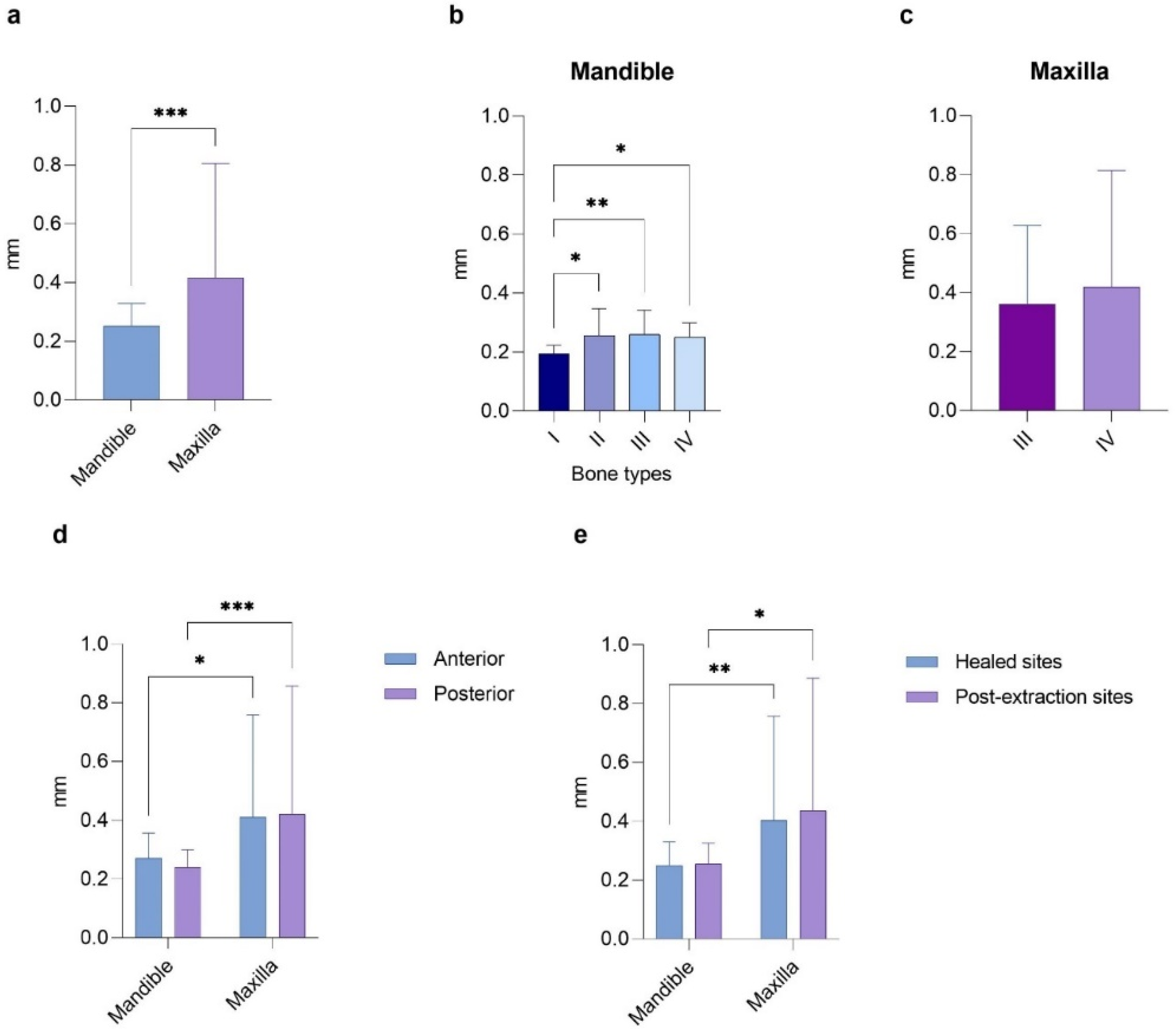
In detail, the analysis in
Figure 4 examined how the discrepancy in implant placement at the entry point varies concerning the arch, bone density, anterior or posterior regions of both arches, and healed or post-extraction sites. In the first case, the Mann–Whitney test revealed significantly higher values in the maxilla than the mandible (0.42 ± 0.39 mm vs. 0.25 ± 0.08 mm,
p < 0.001). Notably, statistically significant mean differences were found between bone type I and the other bone types in the mandible (0.19 ± 0.03, 0.26 ± 0.09, 0.26 ± 0.08, and 0.25 ± 0.05 mm, with
p < 0.05,
p < 0.01, and
p < 0.05, respectively). In contrast, no significant differences were observed in the maxilla (0.36 ± 0.27 mm for type III and 0.42 ± 0.40 mm for type IV bone). There were no significant differences between the anterior and posterior regions of the same arch (0.27 ± 0.10 mm for the mandible and 0.24 ± 0.06 mm for the maxilla). However, a
p < 0.05 was noted when comparing the anterior regions of the mandible and maxilla, and a
p < 0.001 was found between the posterior areas of the arches. A similar trend was seen when comparing the implants placed in healed and post-extraction sites in the same arch, reporting a
p < 0.01 between the healed sites and a
p < 0.05 between the post-extraction sites of different arches.
Regarding the apical deviations recorded for the implants placed in the mandible or maxilla, a significant difference was found between arches (0.24 ± 0.08 mm vs. 0.55 ± 0.57 mm,
p < 0.0001) and between type I bone and types II and III (
p < 0.01 and
p < 0.05, respectively) in the mandible. Conversely, no statistically significant differences were found between the two bone types in the maxilla. Additionally, the discrepancies in the anterior and posterior maxilla were significantly greater than those in the mandible (0.55 ± 0.53 mm vs. 0.26 ± 0.10 mm,
p < 0.01, and 0.56 ± 0.60 mm vs. 0.23 ± 0.06 mm,
p < 0.0001, respectively). Still, no significant difference was observed between the regions of the same arch. Similarly, the discrepancies of the implants placed in healed or post-extraction sites were significantly greater in the maxilla compared to those in the mandible (0.51 ± 0.45 mm vs. 0.24 ± 0.08 mm,
p < 0.0001, and 0.63 ± 0.72 mm vs. 0.25 ± 0.07 mm,
p < 0.0001, respectively). Still, no difference was reported between the different sites of the same arch (
Figure 5).
The differences in vertical/depth deviations between the mandibular and maxillary locations showed a
p < 0.0001, with an average of 0.24 ± 0.10 mm for the mandible and 0.48 ± 0.46 mm for the maxilla. Furthermore, statistical analysis indicated a small but significant difference between type I and type III bone data in the mandible (0.18 ± 0.04 mm vs. 0.26 ± 0.10 mm,
p < 0.05), while no noticeable differences were found among the other bone types or in the maxilla. Conversely, the mean deviations between the planned and actual positions for the implants placed in the anterior regions of both the mandible and maxilla revealed significant differences (
p < 0.001), as did those comparing the posterior regions (
p < 0.001). Additionally, the discrepancies between the implants placed in either healed mandibular sites or post-extraction sites were shown to be significantly different (
p < 0.001), in contrast to the healed or post-extraction sites of the same arch (
Figure 6).
Finally,
Figure 7 shows the angular deviations of the planned and placed implants while comparing different conditions. Interestingly, we found that the degree of statistical differences in implant accuracy between the mandible and maxilla was not significant, nor was there a notable difference between the two maxillary bone densities. However, a small but noticeable difference was observed between type I and type IV bone in the mandible (0.04 ± 0.07° vs. 0.48 ± 0.72°,
p < 0.05). A
p < 0.01 was also noted between type II and type IV bones in the same arch. Moreover, the region of the arch (anterior/posterior) or the implant site (healed/post-extraction) showed no effect on the angular deviation.
Briefly, the overall mean deviation between the planned and placed implants was significantly higher in the maxilla at the entry, apical, and vertical levels compared to the mandible, while the angular deviation reported similar values. For the latter parameter, only the subgroup analysis among mandibular bone types revealed significant differences between bone types I and IV and between bone types II and IV. No statistically significant deviation was reported between the anterior and posterior regions of each arch, nor between the implants placed in the healed and post-extraction sites within the same jaw. Conversely, a greater discrepancy was observed in the posterior and anterior maxilla compared to the posterior and anterior mandible, respectively. This trend was mirrored by the post-extraction and healed sites in the maxilla compared to the same sites in the mandible.
4. Discussion
Currently, dental implant placement can be achieved through free-hand techniques, sCAIS, or dCAIS. Only static guidance is commonly employed in clinical practice between the two guided approaches. DCAIS, particularly when utilized in a flapless or mini-flap approach, confers several advantages and reduce inaccuracies during implant placement compared to static and especially free-hand methods, with an average angular deviation of less than 4°. However, it is advisable to incorporate a 2 mm safety margin, as certain studies have recorded deviations exceeding 1 mm [
19,
28,
29]. The advantages of dCAIS include the unimpeded ability to directly observe and irrigate the surgical site without hindrance from the surgical guide, enhanced control of temperature during the use of surgical burs, the capacity to modify surgical planning during the procedure, the absence of necessity for a specific set of drills or instruments, and real-time verification of position accuracy. A recently developed dCAIS system obviates the need for radiological fiducials and accomplishes CBCT registration by tracing at least three predefined points on the remaining teeth, potentially mitigating inaccuracies resulting from the movement of radiological fiducials. Another notable advantage is the broad applicability of this system to almost all patients, in contrast to sCAIS, which may be unsuitable for cases with limited mouth opening. Additionally, the capability to virtually plan a surgical procedure and subsequently execute it with minimal complications, reduced chair time, heightened predictability, improved comprehension of anatomy and prosthetic plans, and a high success rate holds the potential to enhance both provider and patient satisfaction [
28,
30,
31]. Although it is generally advised that a clinician’s learning curve should encompass a minimum of 25–50 implant procedures to yield highly favorable outcomes, the accurate installation of implants is widely acknowledged as a pivotal factor for ensuring the long-term success of the implants, especially in the case of biconometric implants that require precise parallelism among multiple implants [
28,
29]. However, the deviation in dental implant placement arises from potential errors in image acquisition, tracking systems, image data processing, the level of guidance in osteotomy and implant placement procedures, registration procedures, and human error. Furthermore, dCAIS notably prolongs surgical and registration times, necessitates a clear line of sight between tracking cameras and sensors, and entails a relatively high acquisition cost for navigation equipment. Intraoperative complications must also be considered, such as displacement of optical markers, inaccurate calibration of the drill axis or tip, and imprecise handling of the drills. Lastly, postoperative assessment errors, including CBCT distortion caused by the implant and discrepancies when overlapping pre- and postoperative CBCTs, may impact research outcomes, albeit typically lacking clinical significance [
28,
32,
33]. Certain variables may introduce inaccuracies and should be carefully controlled, as the accuracy of this technique heavily relies on the navigation system, indicating its potential for widespread application in digital implantation.
Achieving parallelism is crucial for placing multiple dental implants that support a fixed dental prosthesis, especially regarding conometric implant–abutment and prosthetic connections (biconometry). Parallelism ensures a uniform insertion path for all prostheses, allowing for cap retention through a streamlined design, improved contour, and a prosthesis that effectively directs forces along the long axis of the implant fixtures. Furthermore, this simplifies the prosthetic insertion and removal process by utilizing the CLIKSS technique. Without such parallelism, clinicians may have to resort to more complex prosthetic manipulations, such as multiple custom or angled abutments, cement retention, and angled screw channels. These more intricate restorations can increase both complexity and costs while also posing greater risks of technical and biological complications. Additionally, the compromised emergence profile associated with angled abutments and the risks of cement retention can lead to a higher incidence of peri-implant tissue inflammation. The biomechanics of the prosthesis–implant complex can also be compromised by misdirected occlusal forces away from the long axis of the implant, resulting in increased stress on the prosthesis components, the implants, and the bone, thereby heightening susceptibility to issues like prosthesis or abutment screw loosening [
10,
11,
34].
Based on this, the primary objective of this retrospective study was to evaluate the accuracy of implant positioning using dCAIS in full-arch rehabilitations with a definitive prosthesis-type Toronto Bridge utilizing biconometry. This study also aimed to assess the impact of various anatomical factors, such as jaw arch (mandible vs. maxilla), jaw regions (anterior vs. posterior), bone density (types I, II, III, and IV), and the placement of implants in healed or post-extraction sites. This research conducted a comparative analysis of discrepancy measurements, including crestal, apical, vertical, and angular deviations. Notably, there remains a lack of in vivo studies documenting the influence of diverse anatomical conditions on accuracy outcomes. Furthermore, the present work represents the initial documentation on using dCAIS for conometric/biconometric implant placement and the CLIKSS splinting technique.
After evaluating a total of 366 implant placements, this research found that the overall measurement errors ranged between 0.24 ± 0.10 mm and 0.55 ± 0.57 mm for linear and 3D measurements and from 0.32 ± 0.65° to 0.35 ± 0.71° for angular deviations. These results were significantly lower than those obtained using most sCAIS methods and much lower than those from a free-hand approach. The errors for sCAIS were approximately 1 mm and 2–4°, while for the free-hand technique, they were about 2 mm and 4–10° [
33,
34,
35,
36]. More specifically, in the comparison of accuracy measurements between the planned and placed implants in the mandible and maxilla, statistically significant differences were observed at the entry (0.25 ± 0.08 mm vs. 0.42 ± 0.39 mm,
p < 0.001), apical (0.24 ± 0.08 mm vs. 0.55 ± 0.57 mm,
p < 0.0001), and vertical (0.24 ± 0.10 mm vs. 0.48 ± 0.46 mm,
p < 0.0001) levels, while no differences were reported in the angular deviation (0.35 ± 0.71° vs. 0.32 ± 0.65°). Additionally, variations in accuracy were noted among different bone densities, especially in mandibular bone types, where statistical significance was reported (type I vs. II, III, IV at the entry point; type I vs. II and III at the apical point; type I vs. type III at the vertical apex; and type I and II vs. IV at the angle). Discrepancies between the anterior and posterior regions of both arches were also observed, with the maxillary regions showing significantly greater discrepancies compared to the corresponding mandibular regions across all the analyzed parameters, except for angular deviation, indicating values ranging from 0.33–0.55 mm (vs. 0.23–0.29 mm) in the anterior region and 0.30–0.56 mm (vs. 0.23–0.39 mm) in the posterior region. When considering the influence of implant site (healed or post-extractive) on implant insertion accuracy, similar trends to those observed within the jaw regions were noted. Specifically, it was consistently observed that the post-extraction sites in the maxilla exhibited greater deviations compared to their mandibular counterparts across all analyzed parameters, except for angular deviation. They ranged from 0.41 to 0.63 mm (vs. 0.17–0.26 mm) for the post-extraction sites and from 0.27 to 0.51 mm (vs. 0.24–0.44 mm) for the healed sites. No statistically significant differences were detected between the two tested groups within the same jaw. Furthermore, there were no differences observed in the success rates of the implants from various brands, regardless of their lengths and diameters. Osseodensifying drills have proven beneficial in low-quality bone sites, leading to improvements in IT and ISQ values. In cases of D1 bone quality, particularly within the mandibular intraforaminal region, there was insufficient preparation of insertion sites to avoid excessive IT.
The accuracy values obtained in the present study were notably lower than those reported in other in vivo studies utilizing dCAIS, regardless of the system brand. For instance, Block et al. [
33] demonstrated an accuracy of approximately 0.87 mm at the entry point, 1.56 mm at the 3D apex, and 3.62° at the angle. Similarly, Geng et al. [
37] detected a coronal deviation of approximately 0.76 mm, an apical deviation of 0.90 mm, a vertical deviation of 1.11 mm, and an angular deviation of 1.48°. Additionally, a systematic review by Jorba-Garcia et al. [
34] in 2023 revealed an overall mean deviation across 10 clinical studies employing nine different dCAIS, with reported values of 1.03 mm at the coronal level, 1.34 mm at the 3D apical level, 0.90 mm at the vertical apex, and 3.68° at the angle, without significant differences among the dCAIS systems. Furthermore, recent studies employing the same navigated system (Navident, ClaroNav Inc., Toronto, ON, Canada) reported deviations ranging from 0.67 mm to 1.01 mm for coronal deviation, 0.90 mm to 2.20 mm for apical deviation, 0.55 mm to 1.20 mm for vertical deviation, and 2.26° to 4.27° for angular deviation [
22,
38,
39,
40,
41]. In summary, current navigated systems consistently demonstrate deviations of 1 mm or less at the entry point, 1 to 1.5 mm at the apical level, and 2° to 4° at the angle. These findings align with the existing literature on the use of sCAIS, suggesting that most dCAIS techniques discussed in current publications are at least as accurate as traditional registration methods [
19,
32,
34].
Nonetheless, most current studies in the literature on the application of dCAIS have been conducted in vitro and generally report slightly reduced deviations compared to clinical outcomes [
28]. For instance, Bose et al. [
42] reported accuracies of 0.78 ± 0.45 mm at the entry point, 1.08 ± 0.50 mm at the 3D apex, 0.32 ± 0.22 mm at the vertical apex, and 2.81 ± 2.29° at the angle. Similarly, Wei et al. [
43] observed mean deviations of 1.09 ± 0.52 mm at the entry point, 1.17 ± 0.53 mm at the apex, and 1.97 ± 1.04° angular deviation. Although the discrepancies reported in preclinical studies fell within a clinically acceptable range and exhibited potential for clinical application, the present results show even lower deviations than those demonstrated in those investigations [
44].
However, the current body of research has produced conflicting results concerning the accuracy and survival rates of the two guided techniques for implant placement. Additionally, various in vitro and in vivo studies have shown that the deviations in implant placement were significantly lower for dCAIS compared to the free-hand method. Lower outcomes were also noted when comparing dCAIS to sCAIS [
21,
33,
45,
46]. A randomized clinical trial revealed that the mean linear deviations at the shoulder of the planned and placed implants were 1.70 ± 0.13 mm and 1.01 ± 0.07 mm for the freehand and navigation groups, respectively, while the mean linear deviation at the tip of planned and placed implants was 2.51 ± 0.21 mm and 1.83 ± 0.12 mm for the freehand and navigation groups, respectively. In addition, the mean angular deviations were 10.04 ± 0.83° and 5.59 ± 0.39° for the freehand and navigation groups, respectively. All differences in linear and angular deviations between the groups were statistically significant [
41]. On the other hand, other studies have indicated that dCAIS enables precise implant positioning similar to sCAIS, with comparable survival rates of approximately 97% [
30,
34].
Several authors also suggested the combined use of sCAIS and dCAIS, reporting significantly higher accuracy than using the two methods alone or compared to free-hand surgery. This combined approach also eliminates operators’ difficulties when using either method separately [
47,
48]. Pomares-Puig et al. [
49] proposed a double-factor technique that merges both guided approaches in the same surgery, allowing for accurate and predictable minimally invasive implant placement.
Moreover, literature reports have highlighted various potential applications of dCAIS in dentistry beyond its conventional uses. Specifically, dCAIS has demonstrated efficacy, accuracy, and safety in the precise placement of zygomatic implants, eliminating the need for additional pre-interventional radiologic imaging and invasive fiducial marker insertion [
50,
51]. Additionally, digital workflows have been utilized in the pre-surgical planning of implant rehabilitations for resorbed edentulous ridges. This involved assessing the effectiveness of dCAIS and simultaneous computer-aided guided bone regeneration in treating atrophic ridges. Despite patient-centered outcomes falling short of expectations, streamlining the planning, surgical, and prosthetic processes may significantly enhance workflow accuracy [
52]. Another notable application of dCAIS is its integration with piezocision to produce computer-aided design and computer-aided manufacturing (CAD/CAM) surgical guides. This approach aims to minimize iatrogenic damage to vital anatomical structures, reduce the risk of overheating, and improve accuracy during corticotomies [
53].
It should be noted that because of various execution methods and the use of imaging, matching, and measurement techniques (such as mesh, surface extraction, and vector registration), the results found in the literature may be skewed. However, it can be inferred that regardless of the navigation technology employed, these advanced devices offer superior accuracy compared to the free-hand method. Furthermore, no critical collisions were reported, affirming the safety of these devices. Both the dCAIS and sCAIS systems are reliable options that enable clinicians to place dental implants precisely, though there remains an increase in deviations at the tip of the implant [
41]. Based on the findings of this study, it has been demonstrated that the use of dCAIS has the potential to significantly reduce discrepancies between planned and placed implants. This holds true regardless of the implant brand or anatomical site when compared to the free-hand and sCAIS methods reported in previous in vitro or in vivo studies. However, these results should be interpreted cautiously. Several limitations must be acknowledged, such as the retrospective nature of this study, which inherently introduces biases like selection and information bias that may impact the generalizability of the findings. Second, the high heterogeneity in the variables involved and the lack of a direct control group utilizing sCAIS or free-hand placement by the same clinician limit the ability to draw definitive conclusions regarding the superiority of dCAIS. Moreover, although accuracy was quantified using linear and angular deviation metrics, the clinical relevance of these deviations, particularly in terms of prosthetic fit, long-term implant survival, and patient outcomes, was not directly evaluated. It is also important to note that the SDs, particularly in the maxilla and posterior regions, were relatively wide. This indicates a degree of variability that may limit predictability in certain clinical situations. Several factors could contribute to this phenomenon, including lower bone density in the maxilla, limited visual and physical access in posterior sites, and greater anatomical variability in post-extraction sockets. Furthermore, tracking the accuracy of the dynamic system may be reduced in areas with less stable anatomical landmarks or more restricted intraoral space. These sources of error could result in greater deviation despite the guidance system. Future refinements in registration protocols, tracking algorithms, and system ergonomics may help mitigate these limitations and improve reproducibility in challenging implant sites. Lastly, the surgeon’s extensive experience with dCAIS and the learning curve associated with dCAIS may have also influenced the results, as less experienced surgeons might achieve different outcomes. Future prospective, randomized controlled trials comparing dCAIS to sCAIS and free-hand methods under standardized conditions, ideally performed by the same operator, are necessary to validate and expand upon these findings, particularly in light of ongoing technological advancements.
In this regard, the field of implant dentistry is rapidly evolving following recent technological advancements. Notably, in 2020, an innovative robotic-assisted dental implant placement procedure yielded promising outcomes characterized by minimal deviations (apical global deviation of 0.8 mm, coronal global deviation of 0.9 mm, and an angular deviation of 0.53°). This pioneering approach includes visual navigation and haptic guidance, facilitating precise implant treatment planning, osteotomy preparation, and implant placement [
54]. Comparative in vitro analyses have demonstrated the increased accuracy of the robotic system in implant positioning relative to dCAIS, also reporting statistical significance. An entry deviation of 0.96 ± 0.57 mm vs. 0.83 ± 0.55 mm (
p = 0.04), a mean exit deviation of 1.06 ± 0.59 mm vs. 0.91 ± 0.56 mm (
p = 0.04), and a mean angle deviation of 2.41 ± 1.42° vs. 1 ± 0.48° (
p < 0.001) were recorded [
55,
56]. Furthermore, the recent introduction of immersive 3D augmented reality (AR) surgical navigation has significantly enhanced precision. By leveraging AR eyeglasses, clinicians can focus directly on the surgical objective, eliminating the need for a separate monitor. This cutting-edge technology has also demonstrated superior accuracy compared to established free-hand and navigation techniques, reporting 0.90 mm as the mean lateral deviation, 1.18 mm as the global deviation, 0.78 mm as the depth deviation, and 3.96° as the angular deviation [
57]. Robotic surgical technologies and AR with navigation systems—likely combined—have the potential to substantially improve the precision, repeatability, and efficacy of dental implant surgery in the future, which this group is currently emphasizing for further research. However, presently, dCAIS utilizing a tracking system based on a reference marker (checkerboard) remains a highly effective method for implant placement, eliminating the bulkiness of static guides while allowing surgeons to use their preferred instruments, assess bone quality, and ensure adequate drill irrigation. Furthermore, this system is especially beneficial in maintaining implant parallelism, thereby simplifying the planned prosthetic procedures executed according to the project.


 ,
, 


