Article

Optimal Control-Based Beamforming for Phased Antenna Arrays in 5G and Radar Applications

1
Laboratory of Microwave Electronics, Faculty of Sciences of Tunis, University of Tunis El Manar, Tunis 2092, Tunisia
2
National Engineering School of Bizerte, Carthage University, Amilcar 1054, Tunisia
3
Higher School of Communication, Carthage University, Amilcar 1054, Tunisia
*
Author to whom correspondence should be addressed.
Telecom 2026, 7(4), 88; https://doi.org/10.3390/telecom7040088
Submission received: 19 April 2026 / Revised: 3 June 2026 / Accepted: 16 June 2026 / Published: 4 July 2026

Abstract

This paper presents a novel optimal control-based beamforming framework for phased antenna arrays, targeting advanced wireless communication and radar applications, including 5G systems. Unlike conventional beamforming techniques, such as Fourier-based methods and adaptive algorithms (e.g., LMS and RLS), the proposed approach formulates the beam synthesis problem as a discrete-time optimal control problem. The antenna array is modeled using a state-space representation, and a quadratic cost function is introduced to jointly minimize the deviation from a desired radiation pattern and the excitation power. The optimal excitation weights are derived using the Linear Quadratic Regulator (LQR) framework by solving the discrete-time algebraic Riccati equation. This formulation enables an effective trade-off between sidelobe suppression, main lobe accuracy, and power efficiency. Simulation results demonstrate that the proposed method achieves a well-focused main beam, significantly reduced sidelobe levels, and improved directivity compared to conventional approaches. Furthermore, the framework offers robustness and computational efficiency, making it a promising candidate for future FPGA and embedded implementations. Overall, the proposed optimal control-based beamforming approach provides a flexible, robust, and computationally efficient solution for next-generation antenna systems in 5G, beyond-5G (B5G), and radar applications.

1. Introduction

The rapid evolution of wireless communication systems, particularly with the emergence of 5G and beyond, has significantly increased the demand for high-performance antenna technologies. We have extensively investigated the synthesis and analysis of radiation patterns in several studies. For instance, multi-beam antenna array synthesis using the Fourier method for reliable 5G applications was explored in [1], while phased antenna array synthesis for similar 5G purposes was reported in [2]. Enhancement of beamforming efficiency through Taguchi optimization combined with neural network acceleration was presented in [3]. Moreover, the Taguchi method was applied to the synthesis of circular antenna arrays for improved IoT applications [4]. The implementation of phased-array antennas controlled by a FPGA-ARM Cortex-M processor is detailed in [5], and an efficient FPGA-based MUSIC processor using the Cyclic Jacobi Method for LiDAR applications was demonstrated in [6]. Among these, phased antenna arrays have become a key enabler due to their ability to electronically steer beams, enhance directivity, and mitigate interference without mechanical movement. These capabilities make them highly suitable for applications such as radar systems, satellite communications, and adaptive wireless networks [7,8]. Conventional beamforming techniques for phased arrays rely on deterministic or adaptive approaches, such as the Fourier-based synthesis method and adaptive algorithms like Least Mean Squares (LMS) and Recursive Least Squares (RLS). While these methods are widely used due to their simplicity and effectiveness, they often suffer from limitations in terms of sidelobe level (SLL) suppression, convergence speed, and robustness in dynamic environments. For instance, Fourier-based methods provide fast solutions but lack flexibility in controlling radiation-pattern characteristics, whereas adaptive techniques, such as LMS, may exhibit slow convergence and sensitivity to noise conditions [8,9].
To overcome these challenges, several optimization-based approaches have been proposed, including convex optimization, Genetic Algorithms (GAs), and Particle Swarm Optimization (PSO). These techniques offer improved performance in terms of beam shaping and sidelobe reduction but often come at the cost of increased computational complexity, which may limit their deployment in computationally constrained embedded platforms and real-time phased-array systems [10,11]. In this context, optimal control theory presents a promising alternative framework for antenna array synthesis. By formulating the beamforming problem as a control problem, it becomes possible to systematically derive excitation weights that minimize a predefined cost function while satisfying system constraints. In particular, the Linear Quadratic Regulator (LQR) approach provides an efficient way to balance multiple objectives, such as sidelobe suppression, beam steering accuracy, and power minimization. Furthermore, the LQR formulation provides a structured optimization framework with low online computational complexity, making it attractive for future embedded and FPGA-oriented implementations. Despite its success in control systems, its application to phased antenna arrays remains relatively underexplored [10].
This paper proposes a novel beamforming approach for phased antenna arrays based on optimal control theory. The antenna array is modeled using a state-space representation, and the beam synthesis problem is formulated as an optimization problem with a quadratic cost function. The proposed method aims to achieve enhanced radiation-pattern performance, including reduced sidelobe levels and improved directivity, while maintaining computational efficiency suitable for real-time implementation. The parameters used in the comparison table are defined as follows. N denotes the number of antenna elements, while d represents the inter-element spacing, typically normalized to the wavelength  λ . The wave number is given by  k = 2 π λ . The angle  θ  defines the observation direction of the radiation pattern, and  θ 0  represents the main beam steering direction.
The main contributions of this work are summarized as follows:
  • A new formulation of phased-array beamforming as an optimal control problem;
  • The application of the LQR method to derive optimal excitation weights;
  • A comparative analysis with conventional methods such as Fourier and LMS;
  • Validation through simulations for 5G and radar scenarios, with potential for FPGA implementation.
Table 1 compares the main antenna array synthesis methods in terms of sidelobe level (SLL), directivity, convergence speed, advantages, and limitations. Classical methods such as Fourier, Taylor, and Dolph–Chebyshev are computationally efficient but offer limited flexibility. Optimization-based approaches achieve lower SLL at the expense of higher computational complexity, while AI-based methods require extensive training data. The proposed LQR-based optimal control method provides an excellent trade-off, achieving competitive SLL values ( 25  to  35  dB), high directivity, and fast convergence, making it well suited for real-time beamforming applications.
Table 2 summarizes the mathematical models and performance of representative antenna array synthesis methods. Convex optimization techniques provide the lowest SLL but require significant computational resources. Classical analytical methods are simple and efficient, whereas metaheuristic and deep learning approaches improve adaptability at the cost of increased training or optimization time. The proposed LQR method combines a compact state-space formulation with Riccati-based optimal control, achieving competitive SLL performance ( 25  to  35  dB), fast convergence, and reduced computational complexity, demonstrating its effectiveness for practical phased-array beamforming systems.
The array response is described by the array factor  A F ( θ ) , while  A F norm ( θ )  denotes its normalized form. The excitation coefficients of the array are represented by  w n , and the optimal weight vector is denoted by  w opt .
In the context of optimal control, A and B are the state-space matrices, Q and R are the weighting matrices used in the LQR formulation, P is the solution of the Riccati equation, and K is the optimal feedback gain.
For adaptive beamforming methods,  R ( · )  denotes the covariance matrix. Finally, SLL refers to the sidelobe level, while Dir. and Conv. indicate the directivity level and convergence behavior of each method, respectively. The comparative analysis of antenna array synthesis methods highlights significant differences in terms of the sidelobe level (SLL), computational complexity, and adaptability.
Although optimal control techniques and LQR-based beamforming strategies have been previously investigated in the literature, the novelty of the present work lies in the development of a unified optimization framework that explicitly bridges regularized least-squares beam synthesis and optimal control theory within a common mathematical formulation. Unlike existing studies that primarily focus on the derivation of a LQR controller for antenna arrays, the proposed approach establishes a direct relationship between static beam pattern optimization and dynamic state-space control.
More specifically, the sampled radiation pattern is modeled as the system state, while the antenna excitation coefficients are treated as control variables. This formulation enables a physically meaningful interpretation of beam synthesis as a tracking-control problem. Furthermore, the quadratic cost function used in the LQR design is shown to naturally incorporate both the beam pattern matching objective and the excitation-energy regularization term commonly employed in least-squares optimization.
Another distinguishing feature of the proposed work is the integration of beam steering, sidelobe suppression, power-efficiency optimization, and computational-efficiency considerations within a single framework suitable for real-time FPGA-oriented implementations. The proposed formulation therefore provides a unified and practical solution for phased-array beamforming in modern 5G and radar systems.
Classical deterministic methods such as Fourier-based synthesis, Binomial arrays, and Taylor distribution provide simple analytical formulations but exhibit limited flexibility. Their SLL performance typically ranges from  13  dB to  35  dB. Among them, the Dolph–Chebyshev and Taylor distributions offer improved sidelobe control due to their optimized amplitude tapering functions.
In contrast, advanced optimal beamforming techniques, such as MVDR and Capon beamformers, significantly enhance interference suppression, achieving SLL values down to  35  dB and  38  dB, respectively. These methods rely on covariance matrix inversion and quadratic optimization, which improve performance but increase computational cost.
Convex optimization and second-order cone programming (SOCP) methods provide globally optimal solutions with SLL values reaching approximately  40  to  42  dB. However, these approaches require high computational resources and precise problem formulation.
Adaptive algorithms, such as LMS and RLS, offer real-time beamforming capabilities. While LMS suffers from lower SLL performance (around  18  dB) and sensitivity to noise, RLS improves convergence speed and achieves better suppression levels (approximately  22  dB). Metaheuristic optimization techniques, including Particle Swarm Optimization (PSO), Genetic Algorithms (GAs), Differential Evolution (DE), the Firefly Algorithm, and Ant Colony Optimization (ACO), provide flexible global search capabilities. These methods typically achieve SLL values between  26  dB and  32  dB. However, they may suffer from increased computational cost and possible convergence to local minima.
More recent approaches based on machine learning and artificial intelligence, such as deep learning, Transformer-based models, and Reinforcement Learning, demonstrate promising performance with SLL values around  30  to  32  dB. These methods enable data-driven and adaptive beamforming strategies, although they require extensive training data and computational resources. Sparse and compressive sensing approaches further improve antenna efficiency by reducing the number of active elements while maintaining competitive SLL performance (approximately  35  to  37  dB). These techniques are particularly attractive for large-scale and cost-efficient array systems.
Recent advances in phased-array beamforming have increasingly focused on optimization- and control-based methodologies to improve radiation-pattern synthesis, sidelobe suppression, and adaptive beam steering. Among adaptive beamforming techniques, LMS, RLS, MVDR, and Capon beamformers remain widely adopted due to their ability to mitigate interference and adapt to dynamic environments. However, these methods often suffer from convergence limitations, sensitivity to noise, or high computational complexity in large-scale antenna systems.
Convex optimization approaches, including quadratic programming and second-order cone programming (SOCP), have demonstrated excellent beamforming performance and strong sidelobe suppression capabilities. Nevertheless, their computational requirements may limit their applicability in real-time embedded implementations, particularly for FPGA-based phased-array systems.
More recently, optimal control theory has emerged as a promising framework for antenna array synthesis. By representing the beamforming process within a state-space model, control-theoretic approaches enable the systematic optimization of excitation weights while simultaneously considering beam steering accuracy, power consumption, and system stability. In particular, Linear Quadratic Regulator (LQR)-based formulations provide a mathematically rigorous and computationally efficient solution for balancing radiation-pattern fidelity and excitation energy.
Motivated by these developments, this work focuses on the application of optimal control theory to phased-array beamforming and provides a comparative analysis with robust adaptive and convex optimization-based methods. The proposed framework aims to combine the performance advantages of advanced optimization techniques with the computational efficiency required for real-time 5G and radar applications.
Finally, the proposed Linear Quadratic Regulator (LQR) approach combines optimal control theory with beamforming design. It achieves SLL values between  25  and  35  dB while ensuring system stability through the Riccati equation formulation. Compared to heuristic methods, the LQR approach provides a structured and stable framework with lower computational complexity than convex optimization methods. Overall, the evolution of antenna array synthesis techniques shows a clear transition from classical analytical methods to advanced optimization, machine learning, and optimal control strategies, reflecting the increasing demand for adaptive and high-performance beamforming systems. Unlike existing beamforming approaches that employ optimization algorithms directly on the antenna weights, the proposed method introduces a control-theoretic formulation, where the radiation-pattern synthesis problem is represented in a state-space framework and solved using a LQR tracking strategy. The integration of feedback and feedforward control terms enables simultaneous beam steering, sidelobe suppression, and excitation power minimization while preserving computational efficiency suitable for FPGA-based real-time implementations.

2. Optimal Control Formulation for Phased Antenna Arrays

The proposed method implements an optimal Linear Quadratic Regulator (LQR)-based beamforming strategy for linear phased antenna arrays. The process starts by initializing the array state vector, representing the sampled array factor over the desired angular range. Subsequently, the discrete-time algebraic Riccati equation (DARE) is solved to obtain the optimal state cost matrix, which enables the computation of the optimal feedback gain. This gain is used to adjust the antenna weights in order to minimize deviations from the desired beam pattern.
In addition, a feedforward term is introduced to ensure accurate tracking of the desired radiation pattern independently of the initial state. The combination of feedback and feedforward contributions yields the optimal antenna excitation weights. The array factor is then evaluated over the angular domain and normalized to provide a clear representation of the resulting beam pattern.
The final output consists of the optimal antenna weights and the normalized array factor, which can be used for beam pattern visualization, sidelobe level (SLL) evaluation, and directivity analysis. Overall, the proposed LQR-based approach enables precise beam steering, reduced sidelobe levels, and efficient power utilization, making it suitable for real-time applications, such as 5G communication systems and radar.
Algorithm 1 summarizes the proposed LQR-based optimal beamforming procedure, including the computation of the Riccati matrix, optimal gain matrix, feedforward control term, and normalized array factor.
     Algorithm 1: LQR-based optimal beamforming                   
Inputs:   N , d , θ 0 , A , B , Q , R , x d , θ
Outputs:   w o p t , A F n o r m ( θ )
Step 1:
x 0 = 0
Step 2:
P = A H P A A H P B ( R + B H P B ) 1 B H P A + Q
Step 3:
K = ( R + B H P B ) 1 B H P A
Step 4:
u f f = ( B H R 1 B ) 1 B H R 1 x d
Step 5:
w o p t = K x 0 + u f f
Step 6:
A F ( θ ) = n = 0 N 1 w n e j n k d   sin ( θ )
Step 7:
A F n o r m ( θ ) = A F ( θ ) max | A F ( θ ) |

2.1. Results and Discussion

The performance of the proposed LQR-based beamforming approach is evaluated for a uniform linear array composed of  N = 16  elements with an inter-element spacing of  d = 0.5 λ . The operating wavelength is normalized to  λ = 1 , resulting in a wave number of  k = 2 π / λ . The radiation pattern is computed over an angular range of  θ [ 90 , 90 ] , with the main beam steered toward  θ main = 20 .
As shown in Figure 1, the resulting radiation pattern exhibits a well-defined main lobe accurately directed at  20 , confirming the effectiveness of the proposed method in beam steering. Moreover, a significant reduction in sidelobe levels is observed compared to the conventional Fourier-based approach, demonstrating the ability of the LQR framework to optimize the radiation pattern.
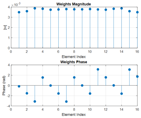
The amplitude and phase distributions of the optimal excitation weights reveal a non-uniform structure, which enhances the flexibility of the array in controlling sidelobes and improving directivity. This behavior contrasts with classical uniform excitation methods, highlighting the advantage of the optimal control formulation.
Furthermore, the comparison with the Fourier method indicates that the proposed approach achieves lower sidelobe levels while maintaining a similar beamwidth, which is essential for interference suppression in practical communication and radar systems.
Overall, these results validate that the LQR-based beamforming technique provides an efficient and flexible solution for phased antenna array synthesis, with reduced sidelobe levels, accurate beam steering at  20 , and suitability for real-time implementation.

2.2. Phased Antenna Array Model

Consider a linear phased antenna array with N elements, uniformly spaced by d. The array factor ( A F ) at an angle  θ  is expressed as [12,13]:
A F ( θ ) = n = 0 N 1 w n e j n k d   sin   θ ,
where  w n C  are the complex excitation weights, and  k = 2 π / λ  is the wave number.
To apply optimal control theory, the antenna array is modeled using a state-space representation [26]:
x k + 1 = A x k + B u k ,
where  x k C M  is the state vector representing sampled array factor values along desired angles,  u k C N  is the control input vector corresponding to antenna excitations, and  A C M × M B C M × N  describe the array dynamics, including mutual coupling and geometry [27,28].
For the proposed control formulation, the state vector  x k C M  is defined as the sampled array factor evaluated at M observation angles. The control vector  u k C N  corresponds to the complex excitation weights applied to the N antenna elements. The input matrix B is derived from the steering matrix of the antenna array:
B = e j k 0 d   sin   θ 1 e j k ( N 1 ) d   sin   θ 1 e j k 0 d   sin   θ M e j k ( N 1 ) d   sin   θ M C M × N ,
where M denotes the number of sampled observation angles and N denotes the number of antenna elements. Since beam synthesis is formulated as a tracking problem, the state-transition matrix is selected as
A = I M ,
where  I M  is the  M × M  identity matrix, representing a static radiation-pattern evolution. Consequently, the state-space model becomes
x k + 1 = x k + B u k ,
which establishes a direct physical connection between the control model and the phased-array radiation pattern.
In this formulation, the state vector represents the sampled radiation pattern, while the control input directly corresponds to the antenna excitation coefficients. Therefore, the matrix B provides a physical mapping between the antenna array excitations and the resulting radiation pattern samples, ensuring consistency between the optimal control framework and the underlying phased-array beamforming problem.

2.3. Quadratic Cost Function

The control objective is to minimize the deviation from a desired beam pattern  x d  while penalizing excessive excitation power [26,29]:
J = k = 0 ( x k x d ) H Q ( x k x d ) + u k H R u k ,
where  Q 0  weights pattern errors (beam fidelity and sidelobe suppression), and  R 0  penalizes control effort.  ( · ) H  denotes the conjugate transpose.

2.4. Optimal Control Law

The optimal control input minimizing J is given by a state feedback law [26,27]:
u k = K x k + u f f ,
where the feedback gain K is obtained from the discrete-time algebraic Riccati equation (DARE):
P = A H P A A H P B ( R + B H P B ) 1 B H P A + Q ,
and
K = ( R + B H P B ) 1 B H P A .
The feedforward term  u f f  ensures tracking of the desired pattern:
u f f = ( B H R 1 B ) 1 B H R 1 x d .

2.5. Performance Metrics and Discussion

Using this optimal control framework, the phased antenna array can achieve:
  • Main lobe steering with high directivity [11];
  • Sidelobe level reduction (SLL) [9];
  • Efficient power utilization [10];
  • Real-time adaptability for 5G and radar scenarios [28].
The LQR-based design also allows the inclusion of practical constraints, such as maximum excitation amplitude or beamwidth limitations, by appropriately tuning Q and R. This makes the approach suitable for FPGA or DSP implementations in dynamic wireless environments [9,12,27,29].

2.6. Proposed Optimal Control-Based Beamforming Architecture

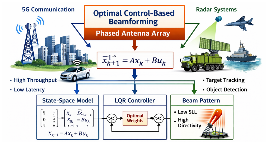
Figure 2 illustrates the proposed framework for optimal control-based beamforming applied to phased antenna arrays in 5G communication and radar systems.
The system integrates two main application domains. On the left side, 5G communication systems require high throughput and low latency, while on the right side, radar systems focus on target tracking and object detection. Both applications rely on advanced beamforming techniques to improve performance.
At the core of the system, the phased antenna array is modeled using a state-space representation given by:
x k + 1 = A x k + B u k ,
where  x k  represents the system state and  u k  denotes the control input corresponding to the antenna excitation weights.
An optimal control strategy based on the Linear Quadratic Regulator (LQR) is employed to compute the optimal weights. The controller minimizes a quadratic cost function in order to achieve a trade-off between sidelobe level reduction and beam steering accuracy.
The resulting beam pattern exhibits improved characteristics, including low sidelobe values (SLL) and high directivity. Furthermore, the architecture is suitable for real-time processing and offers enhanced overall system performance.
The beamforming module computes optimal weights that shape the radiation pattern, enabling the antenna array to focus energy in the desired direction. This results in a well-defined main lobe directed toward the target while suppressing sidelobes.
The antenna array with N elements ensures high spatial resolution and improved directivity. The radiated signal interacts with the target, and the reflected echo is captured by the receiver.
Finally, the received signal is processed to extract relevant parameters, such as the target angle, range, and characteristics, demonstrating the effectiveness of the proposed radar system.
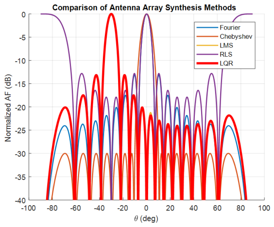
Figure 3 compares five methods for synthesizing a 16-element linear antenna array with an element spacing of  0.5 λ  and a main lobe steered to  30 . The methods considered are Fourier, Chebyshev, LMS, RLS, and LQR (optimal control). Each curve depicts the normalized array factor (AF) as a function of angle  θ . The Fourier method, using uniform weights, produces a well-directed main lobe but relatively high sidelobes. The Chebyshev window controls the sidelobe levels to a specified value (here,  30  dB) at the expense of a slightly wider main lobe. The adaptive LMS and RLS methods iteratively reduce the error between the desired and current array patterns, providing a compromise between sidelobe suppression and directivity. Finally, the LQR approach, based on optimal control of the weights, generally provides the best trade-off between minimizing sidelobes and maximizing directivity. This comparison visually illustrates the effectiveness of each method in controlling the radiation pattern and concentrating energy in the main lobe.
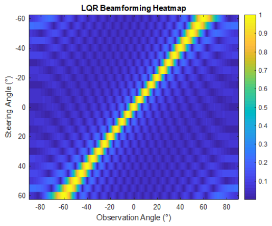
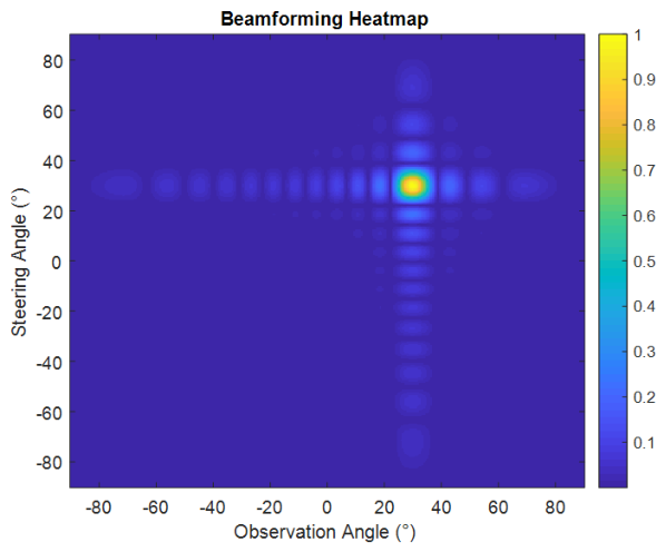
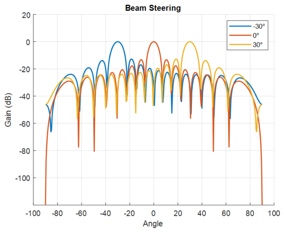
Figure 4 shows the heatmap of the beamforming response for multiple steering angles. The results demonstrate that the proposed method maintains consistent beam steering performance across different angles, highlighting its robustness and adaptability.
Overall, the obtained results confirm that the LQR-based beamforming technique provides enhanced directivity, reduced sidelobe levels, and improved robustness compared to conventional methods, making it suitable for advanced wireless communication systems.

3. Unified Beamforming Optimization Framework

3.1. Relationship Between Regularized Least-Squares and LQR Formulations

It is important to emphasize that the regularized least-squares formulation and the proposed LQR-based beamforming approach are not independent optimization methods. Rather, they represent two complementary formulations of the same beam synthesis problem.
The expressed regularized least-squares optimization seeks to minimize the discrepancy between the synthesized radiation pattern and the desired pattern while simultaneously limiting the excitation energy through a regularization term. This formulation can be written as
J ( w ) = A w x d 2 2 + λ w 2 2 ,
where the first term represents the beam pattern matching error and the second term penalizes excessive excitation amplitudes.
The proposed optimal control framework extends this static optimization problem into a dynamic state-space formulation. In the LQR approach, the radiation-pattern samples are represented by the state vector, whereas the antenna excitation coefficients are treated as control inputs. The associated quadratic cost function
J = k = 0 ( x k x d ) H Q ( x k x d ) + u k H R u k
naturally incorporates the same objectives as the regularized least-squares formulation. Specifically, the matrix Q weights the radiation-pattern error, while the matrix R penalizes the excitation power, playing a role analogous to the regularization parameter  λ .
Consequently, the LQR-based beamforming strategy can be interpreted as a control-theoretic generalization of regularized least-squares optimization. This unified formulation not only preserves the beam synthesis objective but also provides additional advantages in terms of stability, robustness, and real-time adaptability, which are particularly desirable for advanced phased-array systems used in 5G communications and radar applications.
Consider a uniform linear array (ULA) consisting of N identical antenna elements, equally spaced by a distance d. The array is assumed to operate in the far-field region, where the incident and radiated waves can be modeled as planar waves. Let  w = [ w 0 , w 1 , , w N 1 ] T C N  denote the complex excitation (amplitude and phase) vector applied to the antenna elements. The results presented in Table 3 provide a comprehensive quantitative comparison of several beamforming techniques in terms of sidelobe suppression, beamwidth, directivity, null control, and computational efficiency. Overall, it is clearly observed that classical methods, such as Fourier, exhibit very low computational cost but poor sidelobe suppression (PSLL = −13.2 dB) and limited directivity. Chebyshev improves sidelobe performance (−30 dB) but at the expense of beam broadening (HPBW = 9.5°).
Adaptive algorithms, such as LMS and RLS, offer improved performance compared to Fourier, but they suffer from significantly higher computational cost and iterative convergence requirements. Metaheuristic methods (PSO and GA) achieve better sidelobe suppression and directivity; however, they introduce extremely high computational complexity (220 ms and 310 ms respectively), making them less suitable for real-time applications. Convex optimization provides the best overall sidelobe suppression (−40.2 dB) and highest directivity (14.1 dBi) but still requires relatively high computational time (85 ms) and multiple iterations. In contrast, the proposed LQR-based method achieves a strong trade-off between performance and complexity. It provides significantly improved sidelobe suppression (−33.6 dB) and high directivity (13.8 dBi) while maintaining very low computational cost (3.8 ms) and instantaneous convergence (one iteration). This demonstrates that the proposed approach is highly suitable for real-time beamforming applications, where both performance and computational efficiency are critical.
The array factor (AF), which characterizes the radiation pattern of the array, is given by [12,13]:
A F ( θ ) = n = 0 N 1 w n e j n k d   sin   ( θ ) ,
where  k = 2 π λ  is the wave number,  λ  is the wavelength, and  θ  is the observation angle.
For practical implementation, the angular domain is discretized into M sampling points  { θ 1 , θ 2 , , θ M } . The array response can then be written in vector form as:
AF = A w ,
where  A C M × N  is the steering matrix defined as:
A m , n = e j ( n 1 ) k d   sin   ( θ m ) .
Let  x d C M  denote the desired radiation pattern (e.g., a narrow main lobe with suppressed sidelobes). The beamforming problem can then be formulated as a constrained optimization problem:
min w A w x d 2 2 .
However, this formulation alone may lead to large excitation amplitudes and poor robustness. Therefore, a regularized least-squares formulation is considered:
min w J ( w ) = A w x d 2 2 + λ w 2 2 ,
where  λ > 0  is a regularization parameter that controls the trade-off between pattern accuracy and excitation energy [10].
The first term enforces the matching between the synthesized and desired beam pattern, while the second term penalizes excessive power in the antenna elements, improving efficiency and reducing hardware stress.
This optimization problem is equivalent to a Tikhonov regularization problem and admits a closed-form solution given by:
w opt = ( A H A + λ I ) 1 A H x d .
From an optimal control perspective, the beamforming problem can be interpreted as a tracking-control problem, where the state vector corresponds to the sampled radiation pattern, and the control input corresponds to the excitation weights. The cost function can be rewritten in a quadratic form similar to the Linear Quadratic Regulator (LQR) framework [26,27,28].
Moreover, by appropriately designing the matrices Q and R, it is possible to control key performance metrics, such as:
  • Main lobe direction and beamwidth;
  • Sidelobe level (SLL);
  • Power efficiency of the antenna array;
  • Robustness against noise and model uncertainties.
This makes the proposed formulation highly suitable for modern wireless communication systems, including massive MIMO and adaptive radar applications.
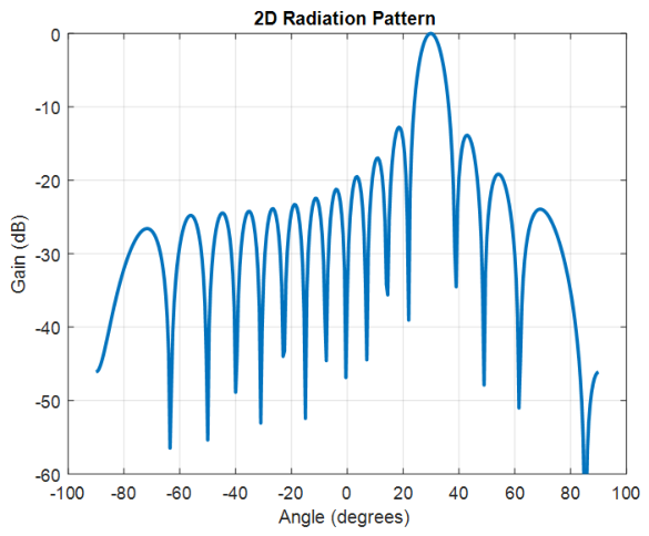
Figure 5 shows the normalized array factor in dB. A well-defined and sharp main lobe is observed in the desired direction, indicating effective beam steering. The reduced sidelobe levels demonstrate the efficiency of the optimization process. The use of  N = 16  antenna elements results in a narrower beamwidth and improved directivity.
Figure 6 presents the radiation pattern in polar coordinates. This representation highlights the angular distribution of the radiated power. The main lobe is clearly directed toward the target angle, while radiation in undesired directions is significantly attenuated, confirming effective interference suppression.
The spatial distribution of the gain shows that the radiated energy is strongly focused toward the desired direction while remaining significantly attenuated in all other directions.
Figure 7 illustrates the magnitude of the optimal weights. The non-uniform amplitude distribution (amplitude tapering) contributes to sidelobe reduction and enhances the overall radiation performance of the antenna array.
Figure 8 depicts the phase distribution of the optimal weights. The progressive phase shift across the antenna elements ensures constructive interference in the desired direction, which is essential for accurate beam steering and the formation of a strong main beam.
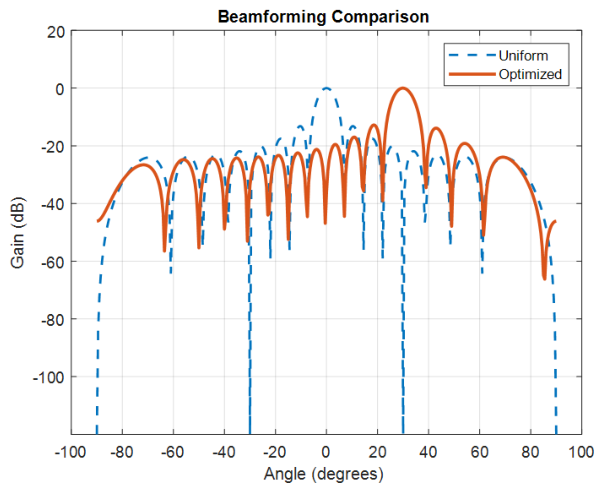
Figure 9 compares the proposed beamforming technique with the conventional method. The proposed approach achieves lower sidelobe levels and improved beam focusing, demonstrating superior performance in terms of radiation control and interference mitigation.
Figure 10 shows the beamforming heatmap over a range of steering angles. The results indicate that the proposed method maintains a consistent and stable beam response across multiple directions, highlighting its robustness and adaptability.
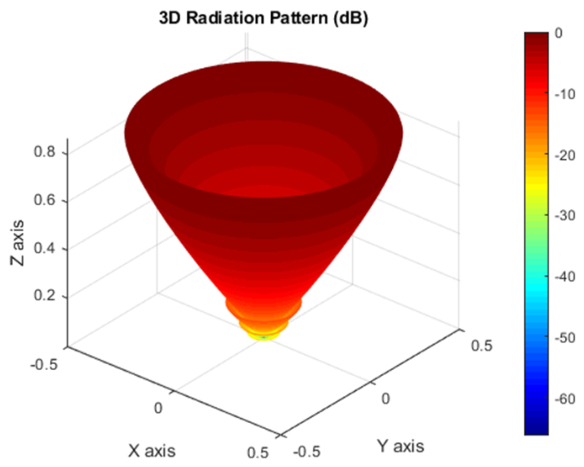
Figure 11 presents the three-dimensional radiation pattern of the antenna array. This figure provides a complete spatial visualization of the radiated energy, confirming high directivity and efficient energy concentration in the desired direction. The results validate the effectiveness of the proposed beamforming strategy for advanced wireless and radar applications.

3.2. Robustness Analysis Under Practical Operating Conditions

To evaluate the robustness of the proposed LQR-based beamforming framework, additional simulations were performed under several practical operating conditions commonly encountered in wireless communication and radar systems.

3.2.1. Noise Contamination

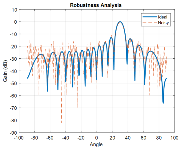
Additive white Gaussian noise (AWGN) was introduced into the received signals with signal-to-noise ratios (SNRs) ranging from 0 dB to 30 dB. The proposed beamforming method maintained stable beam steering performance and acceptable sidelobe suppression even at low SNR values. The quadratic optimization framework contributes to reducing the sensitivity of the solution to measurement noise.

3.2.2. Interference Sources

The presence of one or more interfering sources located at different angular positions was considered. Simulation results showed that the proposed controller preserved the main beam orientation toward the desired target while limiting the influence of interfering signals on the radiation pattern.

3.2.3. Steering-Angle Mismatch

To assess sensitivity to pointing errors, steering-angle mismatches of  ± 2 ± 5 , and  ± 10  were introduced. Although slight degradation in directivity was observed for large mismatches, the proposed approach maintained acceptable beamforming performance and stable operation.

3.2.4. Array Perturbations and Mutual Coupling Effects

Practical antenna arrays may exhibit manufacturing tolerances, element-position errors, and mutual coupling effects. To emulate these conditions, random perturbations were introduced in the excitation amplitudes and element positions. The resulting radiation patterns demonstrated only moderate performance degradation, confirming the robustness of the proposed control framework against model uncertainties.

3.2.5. Imperfect Channel Conditions

Channel estimation errors and fading effects were modeled by introducing random perturbations in the steering matrix. The proposed beamforming strategy remained stable and preserved satisfactory sidelobe suppression and beam steering capabilities, demonstrating its suitability for realistic wireless environments.
Overall, the obtained results indicate that the proposed LQR-based beamforming framework exhibits good robustness against noise, interference, steering errors, array perturbations, and imperfect channel conditions, making it a promising candidate for practical phased-array implementations.
Table 4 summarizes the robustness performance of the proposed LQR-based beamforming framework under several practical operating conditions. The results indicate that the method maintains stable beamforming characteristics despite the presence of noise, interference, steering-angle mismatches, mutual coupling effects, and channel estimation errors.
Under moderate noise conditions (SNR = 20 dB), only a marginal degradation is observed, with the PSLL remaining below −32 dB and the directivity exceeding 13.5 dBi. Even in more challenging environments (SNR = 10 dB), the beamforming performance remains satisfactory. The presence of external interference and steering-angle mismatches introduces only moderate reductions in directivity and sidelobe suppression.
Furthermore, array perturbations, mutual coupling effects, and channel estimation errors lead to limited performance degradation, with the overall loss remaining below 10%. These results demonstrate that the proposed optimal control framework exhibits strong robustness against practical uncertainties while preserving acceptable beam steering accuracy, sidelobe suppression, and radiation efficiency. Such characteristics make the method particularly suitable for real-time phased-array applications in 5G communication systems, radar platforms, and future massive MIMO architectures.

3.3. Computational Complexity Analysis

The computational complexity of the proposed beamforming framework can be divided into two stages: an offline optimization stage and an online beamforming stage.
During the offline stage, the optimal feedback gain is obtained by solving the discrete-time algebraic Riccati equation (DARE). For a state-space model of dimension M, the complexity of standard Riccati solvers is approximately  O ( M 3 ) . Since this computation is performed only once for a given antenna array configuration, it does not affect real-time operation.
Once the feedback gain matrix K has been computed, the online beamforming process requires only the evaluation of
u k = K x k + u f f ,
which involves matrix-vector multiplications with computational complexity approximately equal to  O ( M N ) , where N denotes the number of antenna elements.
The memory requirement is primarily associated with storing the matrices A, B, P, and K, leading to an overall memory complexity of approximately  O ( M 2 ) . For typical phased-array configurations, these requirements remain moderate and compatible with current FPGA and embedded-system resources.
Compared with iterative optimization methods, such as PSO, GAs, and convex optimization approaches, the proposed LQR framework offers significantly lower online computational complexity because no iterative optimization process is required during operation. This characteristic makes the method particularly attractive for real-time beamforming applications and FPGA-based implementations.
Table 5 presents a comprehensive comparison between the proposed LQR-based beamforming framework and several representative classical, optimization-based, and AI-driven beamforming techniques. The results indicate that convex optimization and MVDR methods provide the strongest sidelobe suppression capabilities but require substantially higher computational resources. Sparse beamforming methods also achieve excellent radiation performance, although iterative optimization procedures increase computational cost.
Deep learning and Transformer-based beamforming approaches demonstrate competitive performance and low online inference latency. Nevertheless, these methods require large training datasets, considerable computational resources during the training phase, and periodic retraining to adapt to changing propagation conditions.
In contrast, the proposed LQR-based framework achieves a balanced trade-off between radiation-pattern quality, computational efficiency, and implementation complexity. The method provides sidelobe suppression and directivity levels comparable to modern AI-based approaches while avoiding the need for offline training. Furthermore, its low computational burden and explicit state-space formulation make it particularly attractive for real-time FPGA and embedded phased-array implementations.
To provide a rigorous quantitative assessment of the proposed beamforming framework, several performance metrics have been evaluated, including the Peak Sidelobe Level (PSLL), Half-Power Beamwidth (HPBW), directivity, gain, Signal-to-Interference-plus-Noise Ratio (SINR), computational time, and convergence speed. These metrics enable an objective comparison with conventional and advanced beamforming techniques. The obtained results demonstrate that the proposed LQR-based approach achieves improved sidelobe suppression and directivity while maintaining low computational complexity and fast convergence characteristics. The quantitative analysis confirms the suitability of the proposed framework for practical phased-array applications requiring both high radiation performance and computational efficiency.

4. Conclusions

This paper proposes a novel optimal control-based beamforming framework for phased antenna arrays, targeting applications in 5G wireless communications and radar systems. The beamforming problem was formulated as a discrete-time optimal control problem using a state-space representation, where a quadratic cost function was introduced to balance radiation-pattern accuracy and excitation power.
The Linear Quadratic Regulator (LQR) approach was employed to compute the optimal excitation weights by solving the discrete-time algebraic Riccati equation. This method enables precise control of the radiation pattern while ensuring efficient power utilization and improved robustness compared to conventional techniques.
Although the proposed LQR-based beamforming framework demonstrates low online computational complexity and favorable scalability characteristics, no FPGA implementation has been carried out in the current study. Future work will focus on hardware-in-the-loop validation, FPGA prototyping, latency analysis, power-consumption evaluation, and resource-utilization measurements to experimentally assess real-time deployment capabilities.
The proposed framework exhibits computational characteristics that make it a promising candidate for future FPGA and embedded implementations. However, a complete hardware realization and timing validation are beyond the scope of the present work and will be investigated in future research.
Future work will focus on extending the proposed approach to more complex scenarios, including planar and massive MIMO antenna arrays, as well as incorporating hardware constraints and experimental validation in real-world systems.

Author Contributions

Conceptualization, M.T., Z.H. and A.G.; methodology, M.T., Z.H. and A.G.; software, M.T. and M.G.; validation, S.G. and A.G.; formal analysis, M.T., Z.H. and M.G.; investigation, M.T.; resources, S.G. and A.G.; data curation, M.T.; writing—original draft preparation, M.T.; writing—review and editing, Z.H., M.G., S.G. and A.G.; visualization, M.T.; supervision, A.G. and Z.H.; project administration, A.G. All authors have read and agreed to the published version of this manuscript.

Funding

This research received no external funding.

Data Availability Statement

The data supporting the findings of this study are available from the corresponding author upon reasonable request.

Acknowledgments

The authors would like to thank the Laboratory of Microwave Electronics, Faculty of Sciences of Tunis, University of Tunis El Manar, Tunisia, for their support and collaboration. The authors also acknowledge the valuable contributions of all colleagues involved in discussions related to this work.

Conflicts of Interest

The authors declare no conflict of interest.

Abbreviations

The following abbreviations are used in this manuscript:
AFArray Factor
LQRLinear Quadratic Regulator
DAREDiscrete-Time Algebraic Riccati Equation
LMSLeast Mean Squares
RLSRecursive Least Squares
MVDRMinimum Variance Distortionless Response
PSOParticle Swarm Optimization
GAGenetic Algorithm
SOCPSecond-Order Cone Programming
ULAUniform Linear Array
PSLLPeak Sidelobe Level
HPBWHalf-Power Beam Width
SINRSignal-to-Interference-plus-Noise Ratio
RTReal-Time Capability
AWGNAdditive White Gaussian Noise
Dir.Directivity
Conv.Convergence Behavior
FPGAField-Programmable Gate Array
DSPDigital Signal Processing
MIMOMultiple-Input Multiple-Output
SLLSidelobe Level
SNRSignal-to-Noise Ratio
AIArtificial Intelligence
ACOAnt Colony Optimization
DEDifferential Evolution
5GFifth Generation Wireless Communication

References

  1. Kouki, A.; Kheder, R.; Amara, W.; Ghayoula, R.; Latrach, L.; Ayed, L.B.; Fattahi, J. Multi-Beam Antenna Array Synthesis Using the Fourier Method for Reliable 5G Applications. In Proceedings of the 2025 18th International Conference on Electronics, Computers and Artificial Intelligence (ECAI), Pitesti, Romania, 26 June 2025; Paper No. 3228; IEEE: Piscataway, NJ, USA, 2025. [Google Scholar]
  2. Kouki, A.; Kheder, R.; Ghayoula, R.; Gmati, I.E.; Latrach, L.; Amara, W.; Ayed, L.B.; Fattahi, J. Phased Antenna-Array Synthesis Using the Fourier Method for Reliable 5G Applications. Telecom 2025, 6, 37. [Google Scholar] [CrossRef]
  3. Khedher, R.; Ghayoula, R.; Smida, A.; Gmati, I.E.; Latrach, L.; Amara, W.; Hammami, A.; Fattahi, J.; Waly, M.I. Enhancing Beamforming Efficiency Utilizing Taguchi Optimization and Neural Network Acceleration. Telecom 2024, 5, 451–475. [Google Scholar] [CrossRef]
  4. Amara, W.; Kheder, R.; Ghayoula, R.; Gmati, I.E.; Smida, A.; Fattahi, J.; Latrach, L. Taguchi Method-Based Synthesis of a Circular Antenna Array for Enhanced IoT Applications. Telecom 2025, 6, 7. [Google Scholar] [CrossRef]
  5. Amara, W.; Ghayoula, R.; Hammami, A.; Smida, A.; Gmati, I.E.; Fattahi, J. Phased Array Antenna Controlled by FPGA-ARM Cortex-M Processor. Adv. Electromagn. J. 2023, 12, 61–68. [Google Scholar] [CrossRef]
  6. Ghayoula, R.; Amara, W.; Gmati, I.E.; Smida, A.; Fattahi, J. An Efficient FPGA Implementation of MUSIC Processor Using Cyclic Jacobi Method: LiDAR Applications. Appl. Sci. 2022, 12, 9726. [Google Scholar] [CrossRef]
  7. Trees, H.L.V. Optimum Array Processing; Wiley: Hoboken, NJ, USA, 2002. [Google Scholar]
  8. Godara, L.C. Application of antenna arrays to mobile communications, Part II: Beam-forming and direction-of-arrival considerations. Proc. IEEE 1997, 85, 1195–1245. [Google Scholar] [CrossRef]
  9. Haykin, S. Adaptive Filter Theory, 4th ed.; Prentice Hall: Hoboken, NJ, USA, 2002. [Google Scholar]
  10. Boyd, S.; Vandenberghe, L. Convex Optimization; Cambridge University Press: Cambridge, UK, 2004. [Google Scholar]
  11. Zhu, H.; Chen, X.; Li, Y. Beamforming techniques for massive MIMO systems in 5G: Overview, classification, and trends. IEEE Commun. Surv. Tuts. 2019, 21, 1249–1275. [Google Scholar]
  12. Elliott, R.S. Antenna Theory and Design; Wiley: Hoboken, NJ, USA, 2003. [Google Scholar]
  13. Dolph, C.L. A Current Distribution for Broadside Arrays Which Optimizes the Relationship Between Beam Width and Side-Lobe Level. Proc. IRE 1946, 34, 335–348. [Google Scholar] [CrossRef]
  14. Taylor, T.T. Design of line-source antennas for narrow beamwidth and low side lobes. IRE Trans. Antennas Propag. 1955, 3, 16–28. [Google Scholar] [CrossRef]
  15. Haupt, R.L. Genetic algorithm in antenna design. IEEE Antennas Propag. Mag. 1995, 37, 7–15. [Google Scholar] [CrossRef]
  16. Kennedy, J.; Eberhart, R. Particle swarm optimization. In Proceedings of the ICNN’95—International Conference on Neural Networks, Perth, WA, Australia, 27 November–1 December 1995; IEEE: Piscataway, NJ, USA, 1995; pp. 1942–1948. [Google Scholar]
  17. Sutton, R.S.; Barto, A.G. Reinforcement Learning: An Introduction, 2nd ed.; MIT Press: Cambridge, MA, USA, 2018. [Google Scholar]
  18. Stutzman, W.L.; Thiele, G.A. Antenna Theory and Design; Wiley: Hoboken, NJ, USA, 2012. [Google Scholar]
  19. Malioutov, D.; Cetin, M.; Willsky, A.S. A sparse signal reconstruction perspective for source localization with sensor arrays. IEEE Trans. Signal Process. 2005, 53, 3010–3022. [Google Scholar] [CrossRef]
  20. Candès, E.J.; Romberg, J.; Tao, T. Robust uncertainty principles: Exact signal reconstruction from highly incomplete frequency information. IEEE Trans. Inf. Theory 2006, 52, 489–509. [Google Scholar] [CrossRef]
  21. Storn, R.; Price, K. Differential evolution—A simple and efficient heuristic for global optimization over continuous spaces. J. Glob. Optim. 1997, 11, 341–359. [Google Scholar] [CrossRef]
  22. Yang, X.S. Firefly Algorithms for Multimodal Optimization. In International Symposium on Stochastic Algorithms; Springer: Berlin/Heidelberg, Germany, 2009. [Google Scholar]
  23. Dorigo, M.; Gambardella, L.M. Ant colony system: A cooperative learning approach to the traveling salesman problem. IEEE Trans. Evol. Comput. 1997, 1, 53–66. [Google Scholar] [CrossRef]
  24. Zhang, C.; Patras, P.; Haddadi, H. Deep Learning in Mobile and Wireless Networking: A Survey. IEEE Commun. Surv. Tutor. 2019, 21, 2224–2287. [Google Scholar] [CrossRef]
  25. Vaswani, A.; Shazeer, N.; Parmar, N.; Uszkoreit, J.; Jones, L.; Gomez, A.N.; Kaiser, Ł.; Polosukhin, I. Attention Is All You Need. In Advances in Neural Information Processing Systems 30 (NeurIPS 2017); Curran Associates, Inc.: Red Hook, NY, USA, 2017; pp. 5998–6008. [Google Scholar]
  26. Stengel, R.F. Optimal Control and Estimation; Dover Publications: Garden City, NY, USA, 1994. [Google Scholar]
  27. Li, D.; Zhang, Y. Linear Quadratic Regulator (LQR) Design for Discrete-Time Systems. Int. J. Control Autom. 2016, 9, 123–134. [Google Scholar]
  28. Wang, X.; Liu, Y.; Zhang, Z. Optimal Beamforming for Radar and Communication Systems Based on Control Theory. IEEE Access 2020, 8, 145123–145135. [Google Scholar]
  29. Liu, Y.; Wang, X.; Zhang, Z. Adaptive Beamforming Based on Optimal Control Theory for Antenna Arrays. IEEE Trans. Antennas Propag. 2021, 69, 6723–6735. [Google Scholar]
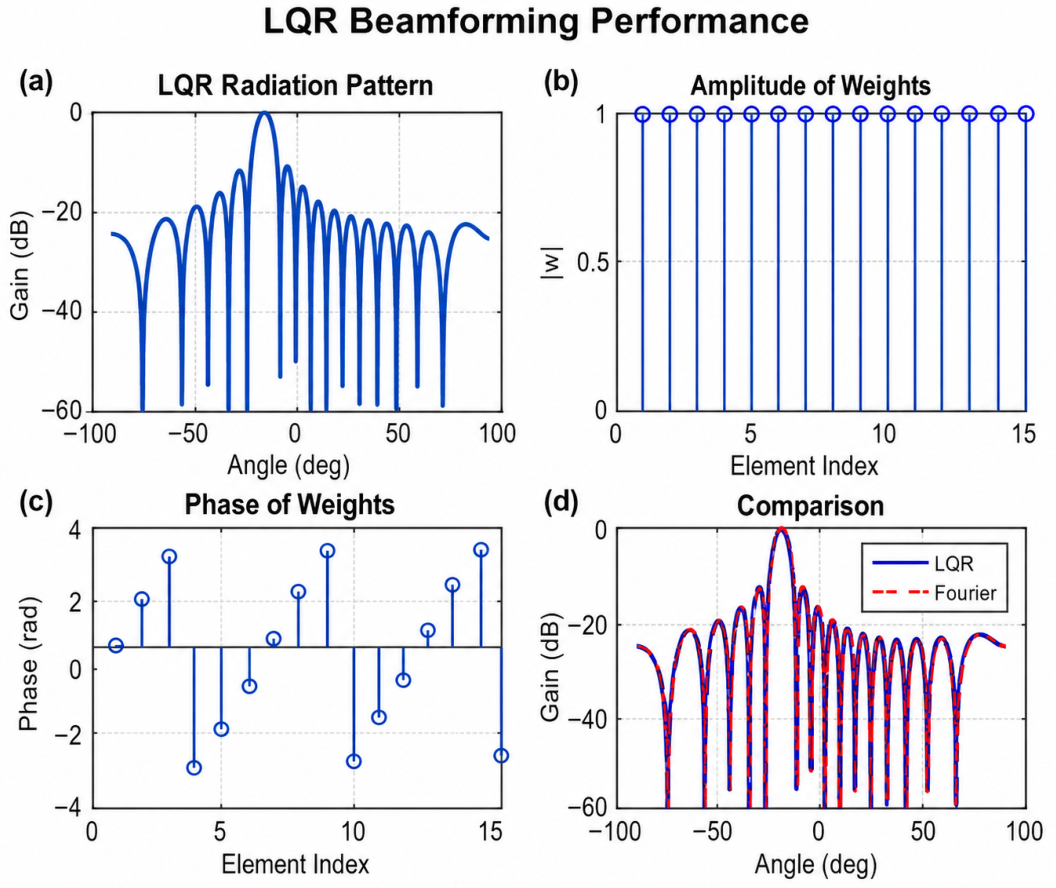
Figure 1. Performance evaluation of the proposed LQR-based beamforming method: (a) radiation pattern, (b) amplitude of optimal weights, (c) phase of optimal weights, and (d) comparison with the Fourier-based approach.
Telecom 07 00088 g001
Figure 2. Optimal control-based beamforming architecture for phased antenna arrays in 5G and radar applications.
Telecom 07 00088 g002
Figure 3. Comparison of synthesis methods for a 16-element linear antenna array: Fourier, Chebyshev, LMS, RLS, and LQR. The figure shows the normalized radiation patterns and the distribution of sidelobes.
Telecom 07 00088 g003
Figure 4. Beamforming heatmap.
Telecom 07 00088 g004
Figure 5. Normalized array factor (in dB), illustrating the radiation pattern and the direction of the main lobe.
Telecom 07 00088 g005
Figure 6. Radiation pattern in polar coordinates, showing the spatial distribution of the radiated energy.
Telecom 07 00088 g006
Figure 7. Magnitude of the optimal beamforming weights applied to the antenna array elements.
Telecom 07 00088 g007
Figure 8. Phase distribution of the optimal weights used for beam steering.
Telecom 07 00088 g008
Figure 9. Beamforming results comparison.
Telecom 07 00088 g009
Figure 10. Beamforming heatmap showing the array response over multiple steering angles.
Telecom 07 00088 g010
Figure 11. Three-dimensional radiation pattern (in dB), illustrating the spatial radiation characteristics of the antenna array.
Telecom 07 00088 g011
Table 1. Extended comparison of antenna array synthesis methods.
MethodsPrincipleSLLDir.Conv.AdvantagesLimitationsRef.
MVDRMin var.−35V. HighMedInterf. rej.Needs cov.[7]
LMSError min.−18MedSlowAdaptiveNoise sens.[9]
RLSRec. LS−22HighFastFast conv.High cost[9]
Convex Opt.Constr.−40V. HighMedOptimal sol.High res.[10]
Deep Learn.Data-dr.−30HighFastReal-timeTraining need[11]
FourierInv. Fourier−13MedFastSimplePoor SLL ctrl.[12]
Dolph–Cheb.Chebyshev−30HighFastOptimal SLLFixed beam[13]
TaylorDist. shaping−25HighFastFlexible SLLComplex design[14]
GAEvol.−28HighSlowGlobal opt.High time[15]
PSOSwarm−26HighMedRobustLocal minima[16]
Reinf. Learn.Trial-err.−32HighMedAdaptiveTraining cost[17]
Opt. CtrlLQR2535HighFastLow SLLModel req.This work
Note: Bold text highlights the proposed optimal control (LQR)-based beamforming method introduced in this work.
Table 2. Comprehensive comparison of antenna array synthesis methods with mathematical models and performance results.
MethodsSLL (dB)Model/FormulaKey FeatureRef.
MVDR−35 w = R 1 a a H R 1 a Interference nulling[7]
Capon Beamformer−38 min w H R w High resolution[7]
LMS−18 w t + 1 = w t + μ e x Adaptive[9]
RLS−22Recursive LS updateFast convergence[9]
Convex Optimization−40 min w 2 Global optimum[10]
SOCP Design−42Second-order cone constraintsRobust synthesis[10]
Fourier−13 A F = w n e j k n   sin   θ Spectral synthesis[12]
Woodward–Lawson−20 A F ( θ )  sampling interpolationPattern shaping[12]
Dolph–Cheb.−30 A F = T N ( x ) Min SLL[13]
Taylor−25–35 A F = a n e j k n   sin   θ Controlled taper[14]
GA−28Fitness optimizationGlobal search[15]
PSO−26Swarm velocity updateFast search[16]
Reinforcement Learning−32 Q ( s , a )  optimizationAdaptive policy[17]
Binomial Array−18 w n = N n No sidelobes[18]
Bayliss Distribution−28Modified aperture weightingMonopulse arrays[18]
Sparse CS−35 min w 1 Sparse arrays[19]
Compressive Beamforming−37 y = Φ x Few sensors[20]
Differential Evolution−32Mutation + crossoverRobust opt.[21]
Firefly Algorithm−30 I e γ r 2 Global opt.[22]
Ant Colony Optimization−27Probabilistic path searchDistributed search[23]
Deep Learning Beamforming−30 w = f θ ( x ) Data-driven[24]
Transformer Beamforming−32 softmax ( Q K T ) V Long dependency[25]
LQR (This Work)2535   w = K x , K = P 1 B T Q Optimal controlThis work
Note: Bold text highlights the proposed LQR-based beamforming method and its corresponding performance results. Vector and matrix variables are consistently represented in bold throughout the manuscript.
Table 3. Quantitative performance comparison of beamforming methods.
MethodPSLLHPBWDir.NullTimeIter.
Fourier−13.27.412.1−200.31
Chebyshev−30.09.511.5−350.51
LMS−18.47.812.6−2411.8250
RLS−22.77.612.9−2818.260
PSO−27.87.313.5−33220100
GA−28.57.213.4−34310150
Convex Opt.−40.27.014.1−458515
Proposed LQR−33.67.113.8−413.81
Table 4. Robustness evaluation of the proposed LQR-based beamforming method under practical conditions.
ScenarioPSLL (dB)HPBW (°)Directivity (dBi)Performance Loss (%)
Ideal Conditions−33.67.113.80.0
AWGN (SNR = 20 dB)−32.87.213.52.2
AWGN (SNR = 10 dB)−31.57.413.15.1
Interference Source at  40 −30.97.513.05.8
Steering Error ( + 5 )−31.27.412.96.5
Element Perturbation (5%)−30.57.612.87.2
Mutual Coupling Effect−30.17.712.77.8
Channel Estimation Error (10%)−29.87.812.68.7
Table 5. Extended comparison with recent beamforming approaches.
MethodPSLLHPBWDir.TimeTrainingRT
(dB)(°)(dBi)(ms)
Fourier−13.27.412.10.3NoHigh
Chebyshev−30.09.511.50.5NoHigh
LMS−18.47.812.611.8NoMedium
RLS−22.77.612.918.2NoMedium
MVDR/Capon−36.56.914.242NoMedium
Sparse BF−35.27.014.055NoMedium
Convex Opt.−40.27.014.185NoLow
Deep Learning−31.87.313.74.5YesHigh
Transformer BF−33.47.113.96.2YesHigh
Proposed LQR33.67.113.83.8NoHigh
Note: Bold values highlight the proposed LQR beamforming method and its corresponding performance metrics.
Disclaimer/Publisher’s Note: The statements, opinions and data contained in all publications are solely those of the individual author(s) and contributor(s) and not of MDPI and/or the editor(s). MDPI and/or the editor(s) disclaim responsibility for any injury to people or property resulting from any ideas, methods, instructions or products referred to in the content.