
Article

A Reconfigurable Radiation Pattern Circular Patch Antenna Using a Square SRR Metasurface for 5G mmWave Applications

1
Information Technology and Systems Modeling Team, Faculty of Sciences, Abdelmalek Essaadi University, Tetouan 93000, Morocco
2
Electronic and Smart Systems Team, Faculty of Sciences, Abdelmalek Essaadi University, Tetouan 93000, Morocco
*
Author to whom correspondence should be addressed.
Telecom 2026, 7(4), 87; https://doi.org/10.3390/telecom7040087
Submission received: 1 May 2026 / Revised: 8 June 2026 / Accepted: 24 June 2026 / Published: 4 July 2026

Abstract

In this paper, a mechanically reconfigurable antenna is proposed to overcome the limitations of conventional patch antennas, particularly their static radiation patterns in millimeter-wave (mmWave) 5G applications. The proposed design integrates a physically rotating metasurface above a compact patch antenna, enabling dynamic beam steering through a simple mechanical rotation. A key contribution of this work is the clear and highly predictable relationship between the metasurface rotation angle and the resulting main lobe direction. By rotating the metasurface to specific positions, the main beam is precisely steered to 0 , 90 , 180 , and 270 in direct correspondence with the metasurface rotation angle. For clarity and conciseness, four representative rotation states are selected and analyzed in this work, although the proposed antenna inherently supports continuous beam steering as a function of the metasurface rotation angle. Full-wave electromagnetic simulations, utilizing a RT/Duroid 5880 substrate, confirm a resonance frequency at 28 GHz with a bandwidth of 1.7 GHz, covering the frequency range from 27.15 GHz to 28.85 GHz. The results confirm notable performance improvements, with the antenna achieving a maximum realized gain of 8.66 dBi and its radiation efficiency increasing from 90 % to 94 % after metasurface integration. The proposed antenna offers a compact structure, high efficiency, and reliable beam steering without the need for complex feeding networks or active components, making it a promising solution for next-generation wireless communication systems.

1. Introduction

The emergence of 5G technology has catalyzed the development of advanced antenna systems capable of addressing the diverse requirements of modern wireless communications. A significant innovation in this field is the implementation of metasurfaces [1], which are widely integrated into reconfigurable antennas. In this context, we categorize reconfigurable antennas into three types: frequency-reconfigurable antennas [2,3], polarization-reconfigurable antennas [4,5], and radiation pattern-reconfigurable antennas [6,7,8,9,10,11]. The latter have been instrumental in advancing cellular communications, wireless local area networks (WLANs), and satellite communications, and are crucial for enhancing performance across a variety of applications.
Metasurfaces, which are two-dimensional geometric structures, consist of sub-wavelength-sized elements. These tiny components give metasurfaces the ability to manipulate electromagnetic waves, an attribute not typically found in conventional materials. Unlike these standard materials, metasurfaces owe their functionality not to their composition but to their meticulously engineered structure. This characteristic gives rise to an unprecedented manipulation of wavefronts, thereby offering broader possibilities in controlling radiation patterns. In essence, they play a key role in advanced electromagnetic wave control [12].
The adoption of millimeter-wave (mmWave) frequencies plays a pivotal role in the ongoing advancement of telecommunications. However, operating in this frequency range presents inherent challenges, including signal degradation due to interference, physical obstructions, and user mobility. To address these issues and ensure optimal coverage, reconfigurable antennas have emerged as a promising solution for enhancing system performance. These antennas can dynamically alter their radiation patterns to adapt to varying operating environments.
This adaptability is achieved through several advanced techniques, such as the integration of metasurfaces, renowned for their exceptional ability to manipulate electromagnetic waves [13,14,15,16]. In addition to metasurface-based approaches, various reconfiguration mechanisms have been developed using active and tunable components to enable dynamic control of antenna performance and beam directionality. For instance, in [17], a PIN-diode-based antenna demonstrates multi-directional radiation with moderate gain and efficiency. Similarly, the design in [18] achieves beam steering in multiple azimuthal directions using a dual-feed configuration combined with PIN diode switching, maintaining stable performance across a wide operational bandwidth.
MEMS-controlled structures have also been explored for dynamic beam reorientation at terahertz frequencies [19], confirming their suitability for advanced THz beam-steering systems. The work in [20] employs a tunable dipole and PIN photodiodes to realize bidirectional beam steering, validated through measurements showing consistent resonance and gain performance.
A mechanically reconfigurable array structure in [21] further demonstrates full azimuthal beam coverage, with both simulations and measurements confirming high gain and aperture efficiency. In [22], a reconfigurable circular antenna array was developed using PIN diodes to generate ten distinct radiation beams within the sub-6 GHz band, demonstrating efficient beam steering over 40 with high gain and wide azimuthal coverage.
Building upon these previously established approaches for radiation pattern control and beam reconfiguration, this work presents a novel approach that leverages the versatility of metasurfaces to overcome the inherent constraints of conventional antenna designs. In this study, we first present the design and simulated performance of a baseline patch antenna to establish a baseline for its radiation characteristics. Subsequently, a reconfigurable metasurface is integrated into the structure to address the intrinsic limitations of the original antenna. The implemented technique involves rotating the metasurface to achieve dynamic beam steering, thereby enabling adaptive control of the radiation pattern. The antenna’s reconfigurable behavior is thoroughly analyzed in both the elevation and azimuth planes, demonstrating its capability to actively steer the main lobe toward desired directions. Unlike previously reported approaches that often suffer from limited gain, reduced radiation efficiency, or both, our proposed design maintains exceptionally high efficiency and stable gain performance. Furthermore, while many existing works are restricted to a limited number of steering angles, our configuration enables a continuous and comprehensive beam-steering capability, where every rotation angle of the metasurface corresponds to a distinct radiation direction. Combined with its compact physical dimensions, this approach facilitates seamless integration into modern communication systems requiring versatile and high-performance beam control. A comprehensive comparison with existing designs confirms the superior performance of the proposed configuration in terms of gain, directivity, and adaptability. Finally, the paper discusses the potential applications of this approach in future 5G and beyond communication systems. Numerical investigations are performed using CST Micowave Studio, while independent cross-validation with Ansys HFSS is conducted to ensure the accuracy and robustness of the reported results.

2. Antenna Design

2.1. Antenna Geometry and Design Procedure

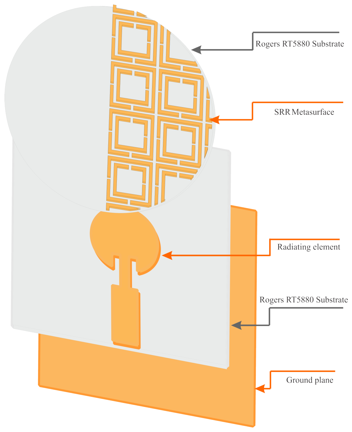
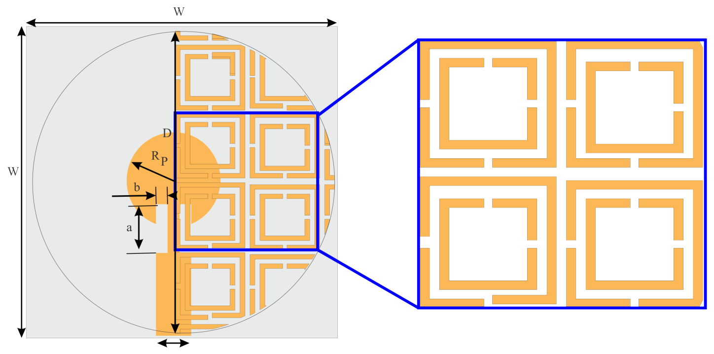
The proposed antenna is a patch antenna with a circular radiating element. The substrate used is R T / D u r o i d 5880 , characterized by a relative permittivity of ϵ r = 2.2 , a thickness of h = 0.508 mm , and an ultra-low loss tangent of tan δ = 0.0009 wich was specifically selected to minimize dielectric attenuation at mmWave frequencies, with square dimensions of 13.4 × 13.4 mm 2 . At a height Z above the radiating element, we place metasurfaces, which consist of square-shaped split-ring resonators, on a circular substrate identical to that of the source antenna. This substrate features a semicircle filled with periodically arranged unit cells. The antenna geometry is developed through a stepwise design process to achieve optimal performance. The initial configuration consists of a simple circular patch antenna fed by a microstrip line. In the subsequent stage, a rectangular slot is introduced into the radiating element to enhance impedance matching and improve antenna performance. Finally, the geometry is further modified by incorporating additional structural features, resulting in the final optimized antenna configuration. This progressive design approach enables improved radiation characteristics and higher gain while maintaining a compact structure. Figure 1 displays the final shape of the proposed antenna after the addition of the metasurfaces.
Figure 2 illustrates the geometry of the proposed antenna, which comprises a square ground plane with a side length of W, a square substrate also measuring W on each side, and a circular patch with a radius of R p . The antenna is excited by a feed line that has a characteristic impedance of 50 Ω . The metasurface is composed of a unit cell, specifically a square-shaped split-ring resonator (SRR), positioned on a circular substrate with a diameter of D.

2.2. Parameter Impact

To obtain optimal performance from the proposed antenna, we study the effects of various antenna parameters, with emphasis on the reflection coefficient and gain. The following outlines the impact of different antenna settings on performance, with each parameter change being analyzed independently.
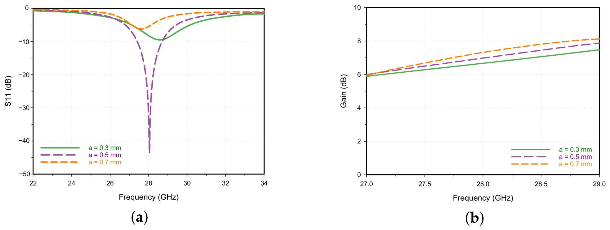
Figure 3 presents the simulated results regarding the influence of parameter a on the antenna performance. First, we investigate the effect of this parameter on the reflection coefficient and gain. As illustrated in Figure 3a, the value of a significantly influences the reflection coefficient. For values of a equal to 0.3 mm and 0.7 mm , the antenna exhibits poor matching, as the reflection coefficient does not reach 10 dB . Conversely, when a is 0.5 mm , the reflection coefficient achieves 43.69 dB at 28 GHz . Figure 3b demonstrates that a has no significant impact on gain, as all three cases yield a gain of approximately 7 dB .
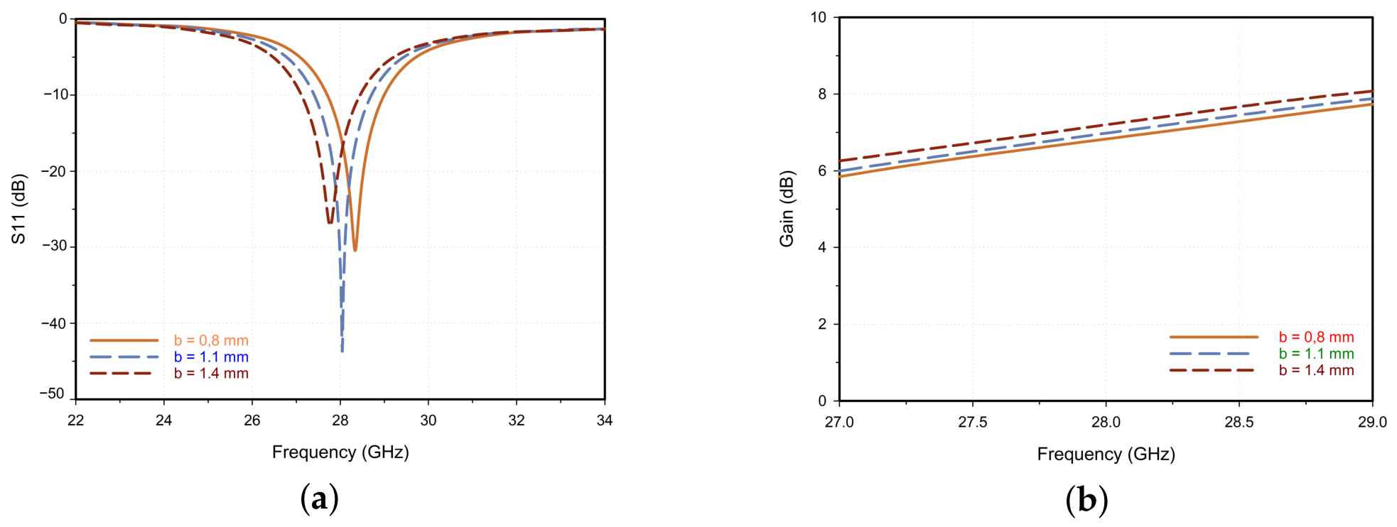
The simulation results concerning the impact of parameter b are illustrated in Figure 4. findings indicate that as b increases, the resonant frequency shifts downward. The optimal value for this parameter is 1.1 mm , resulting in a resonant frequency of precisely 28 GHz , as show in Figure 4a. Furthermore, Figure 4b reveals that the gain remains relatively stable regardless of the variations in b.
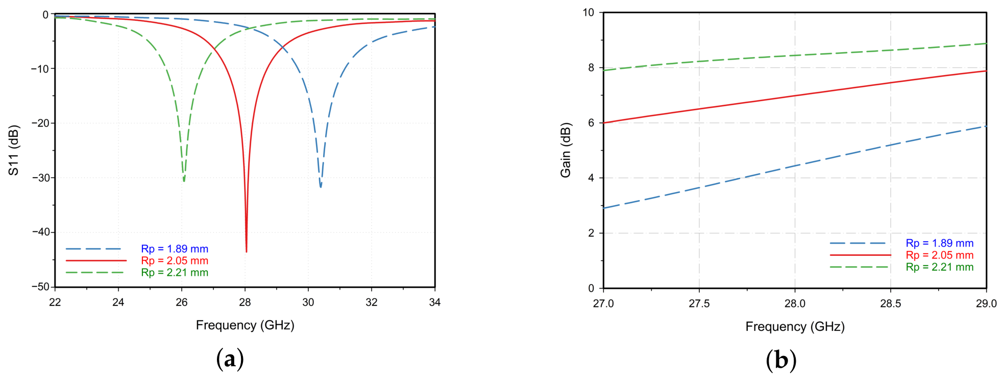
As a third and final step, we investigated the effect of the patch radius R p as show in Figure 5. Specifically, Figure 5a illustrates that the value of R p influences both the reflection coefficient and the resonant frequency. Specifically, as R p increases, the resonant frequency decreases. After optimizing the radius value, we determined that an R p of 2.05 mm yielded the best results, with the reflection coefficient reaching 43.63 dB at a frequency of 28 GHz . Furthermore, the value of R p significantly impacted the maximum gain: at 1.89 mm , the maximum gain reached 4.64 dB , while at 2.05 mm , it increased to 7.12 dB . When R p was set to 2.21 mm , the maximum gain further increased to 8.41 dB (Figure 5b).
After this study, the optimal values for the antenna parameters were identified, yielding the best performance of the proposed antenna. Table 1 provides the dimensions of the proposed antenna.

2.3. Metasurface Array Design

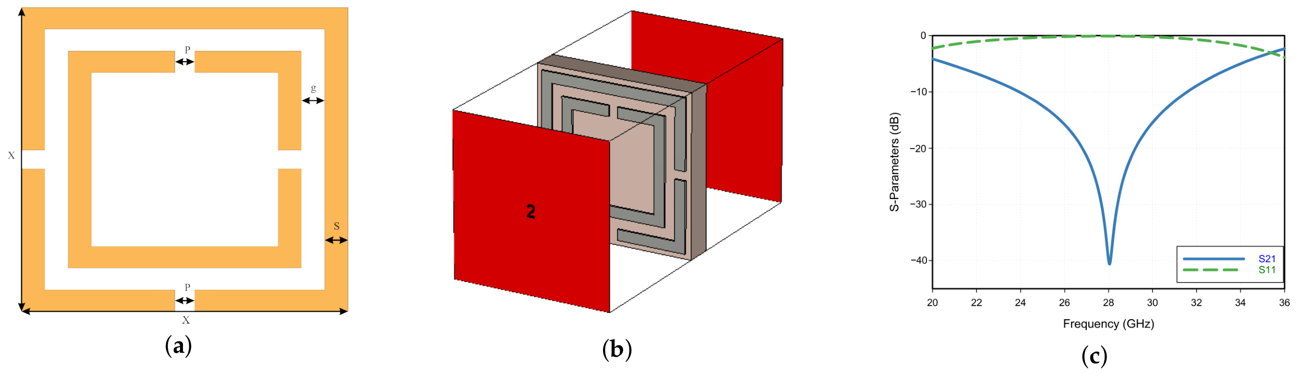
In the domain of modern antenna engineering, metasurfaces have emerged as a pivotal technology for manipulating electromagnetic wave propagation. Within the scope of this research, a metasurface-based approach is adopted to achieve precise radiation pattern control and enhanced gain characteristics. Prior to the full-scale integration with the radiating element, a rigorous characterization of the unit cell—comprising a square-shaped split-ring resonator (SRR)—was performed to validate its resonant behavior. The overall configuration and fundamental performance of the proposed metasurface unit cell are detailed in Figure 6. Specifically, Figure 6a defines the geometric parameters of the unit cell, Figure 6b illustrates the CST model setup with the corresponding port plane excitations, while Figure 6c presents the simulated S-parameters across the frequency spectrum of interest. It is observed that the unit cell exhibits a sharp resonance at 28 GHz, where the transmission coefficient ( S 21 ) reaches a significant notch of −40.63 dB, complemented by a reflection coefficient ( S 11 ) near 0 dB. These results confirm that the metasurface functions as a highly reflective boundary at the operating frequency. By strategically positioning this reflective layer over the antenna, the near-field distribution is effectively redistributed, forcing the radiation to emanate primarily through the unoccupied substrate area, which facilitates the desired beam-steering functionality.
Table 2 presents the values of the unit cell dimensions determined through a series of studies that assessed the effect of each parameter on the reflection coefficient.

3. Results and Discussion

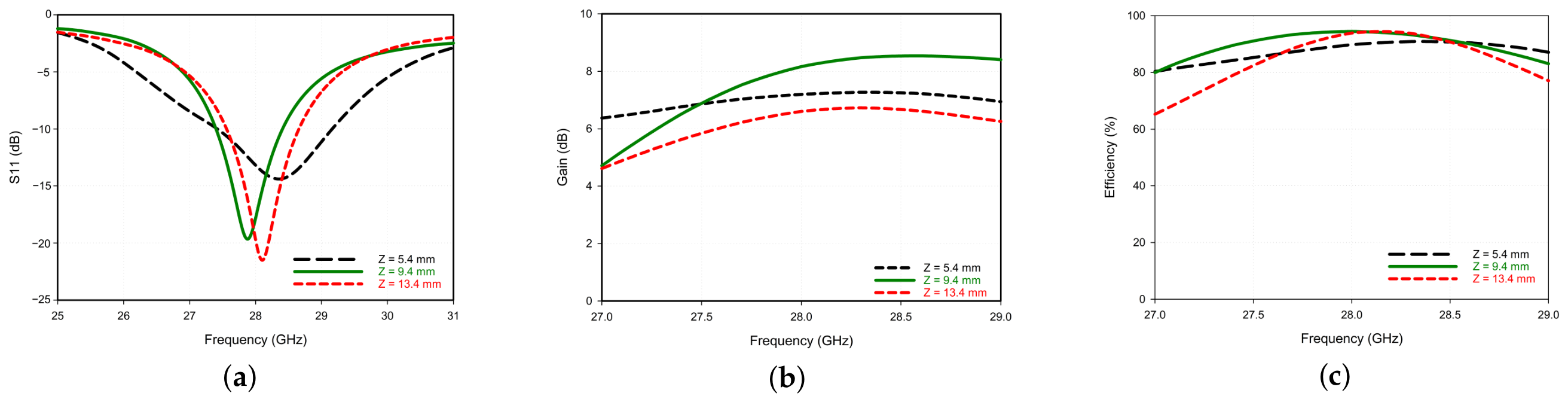
The fundamental performances of the antenna, both in its original state and with the integrated metasurface, are comprehensively evaluated in terms of key metrics such as the reflection coefficient, gain, and efficiency. Initially, a parametric study was conducted to determine the optimal metasurface height (Z), as this distance governs the electromagnetic coupling between the source and the metasurface. Preliminary simulations indicated that at heights significantly lower than λ 0 / 2 , the antenna resonance is entirely suppressed due to extreme near-field loading. Consequently, the analysis was initiated from a minimum height of 5.4 mm (approximately λ 0 / 2 at 28 GHz) to ensure fundamental impedance matching. Figure 7 illustrates the impact of varying Z on the antenna’s performance. As shown in Figure 7a, the minimum height of 5.4 mm causes a downward frequency shift and degrades the impedance matching due to excessive capacitive loading. Conversely, although a larger height of 13.4 mm maintains a stable resonance and high radiation efficiency, as depicted in Figure 7c, it leads to a significant reduction in the realized gain (Figure 7b). This gain drop is attributed to the beam-spreading effect, where a portion of the radiated energy expands beyond the metasurface’s effective aperture before being focused. Accordingly, the height of 9.4 mm was selected as the optimal focal distance, as it provides a perfectly centered resonance at 28 GHz while achieving the maximum peak gain and the most effective radiation concentration.
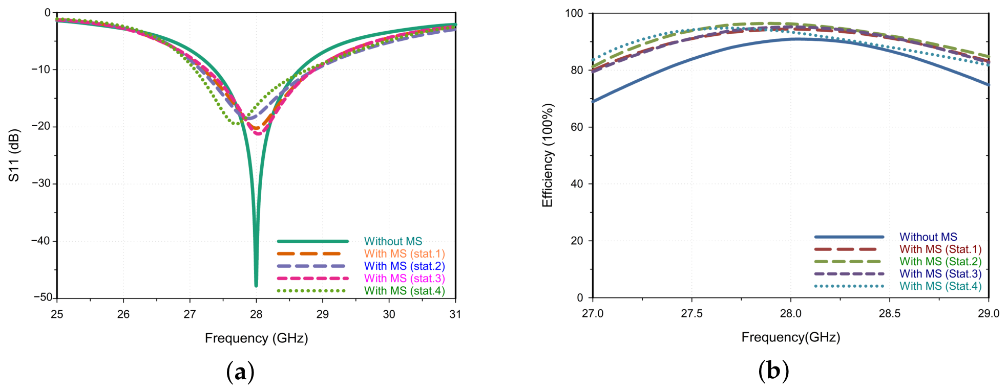
Building on the optimized height of Z = 9.4 mm, the final performance of the reconfigurable antenna system is detailed in Figure 8. Specifically, Figure 8a presents the reflection coefficient ( S 11 ) for both the original antenna and the metasurface-integrated design across its four rotation states. Prior to the integration of the metasurface, the antenna exhibited an excellent impedance match, with a pronounced resonance of 47.45 dB at the central frequency of 28 GHz. This initial configuration demonstrated an operational bandwidth of 1.2 GHz. Upon incorporating the metasurface, the antenna’s operating frequency remained stable at 28 GHz. While the resonance depth was slightly reduced to 20.23 dB, this value still represents a very acceptable impedance match. Notably, the introduction of the metasurface led to a substantial increase in the antenna’s bandwidth, expanding it to 1.7 GHz, which represents a significant enhancement of approximately 500 MHz. Furthermore, Figure 8b compares the total efficiency of the antenna before and after the metasurface integration. The original antenna exhibits a high total efficiency of 90.8 % at 28 GHz. Following the incorporation of the metasurface, the efficiency shows a notable increase, reaching 94 % . This observed improvement, despite a minor degradation in impedance matching, can be attributed to the positive impact of the metasurface on the antenna’s radiation efficiency. The periodic structure likely suppressed unwanted surface waves, converting their energy into useful radiated power and leading to a net improvement in the overall efficiency.
With the fundamental antenna performance established, we now proceed to present and analyze the simulated radiation patterns, which demonstrate the primary functional capability of the reconfigurable design.
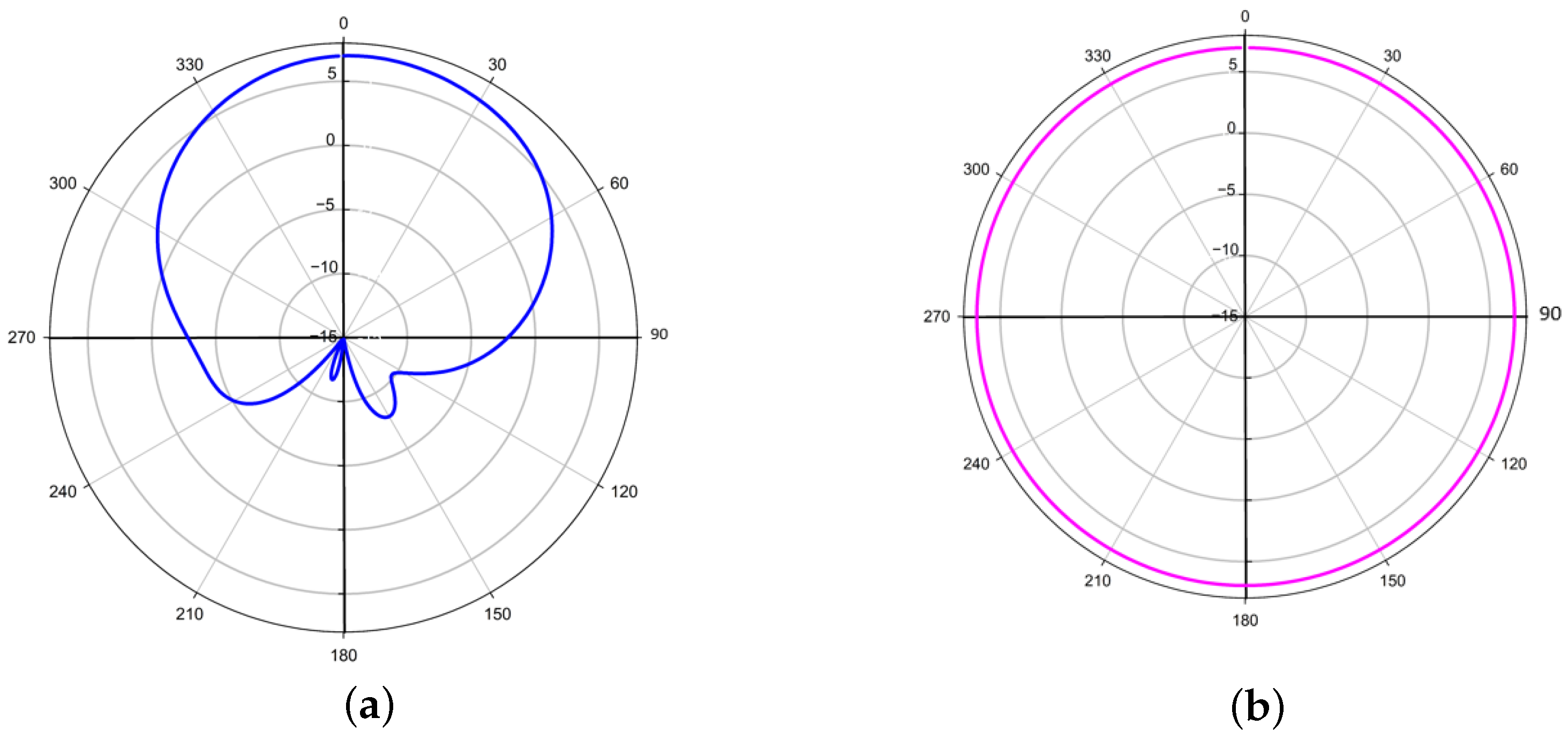
The radiation patterns of the original antenna were investigated to define its performance prior to the metasurface integration. In this study, the azimuth radiation pattern is evaluated in the XY-plane, while the elevation radiation pattern is analyzed in the XZ-plane. The simulated results for both planes are presented in Figure 9. The analysis in the elevation plane (Figure 9a) reveals a directional pattern, where the main lobe is directed at 4 with a maximum gain of 7.01 dBi. Conversely, the azimuth plane’s pattern (Figure 9b) shows an omnidirectional profile with a consistent gain of 7.01 dBi. The static nature of this radiation and the inability to dynamically control the main beam’s direction represent a significant limitation. Consequently, the primary motivation for integrating a reconfigurable metasurface is to overcome this fixed radiation behavior and enable precise control over the beam in multiple directions.
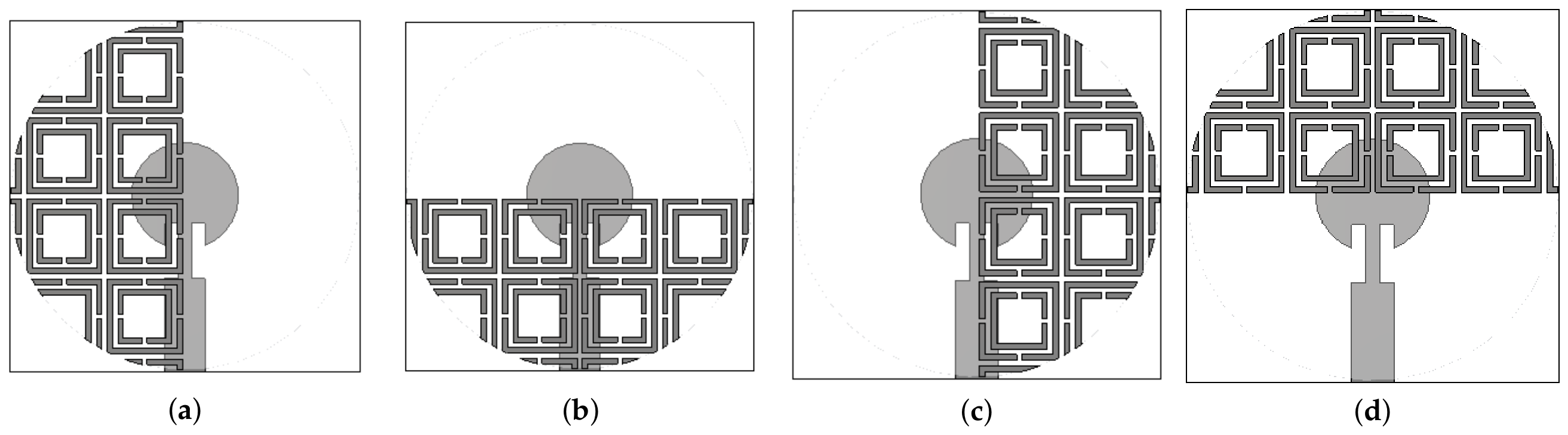
To overcome the limitations imposed by the static radiation pattern of the original antenna, a new reconfigurable design was developed (Figure 1). The fundamental principle of this design is to achieve dynamic beam steering by physically rotating the metasurface. To demonstrate the effectiveness of this approach, we simulated four different cases, corresponding to metasurface rotation angles of 0 (State1), 90 (State2), 180 (State3), and 270 (State4). Each state represents a different configuration, and these four states are presented in Figure 10. The subsequent analysis confirms that this design is a successful and effective solution, as will be detailed through the simulated radiation patterns and gain values for each of these states, proving the antenna’s ability to precisely control the direction of its main lobe.
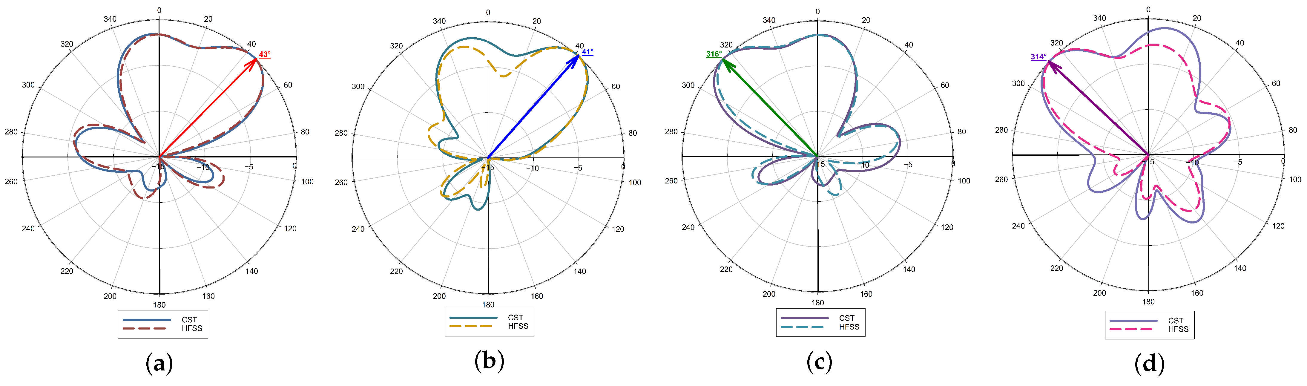
The radiation patterns presented in the following analysis are obtained using full-wave electromagnetic simulations. The radiation pattern of the reconfigurable antenna was analyzed in the elevation plane to evaluate its beam steering capability. As shown in Figure 11a, the first state ( 0 rotation) shows the main lobe directed towards 43 with a gain of 7.54 dBi. In the second state (Figure 11b), rotating the metasurface by 90 steers the main lobe to 41 , with a notable gain increase to 8.66 dBi. For the third state (Figure 11c), a 180 rotation steered the main lobe to 316 (in polar cordinates), achieving a gain of 7.53 dBi. Finally, in the fourth state (Figure 11d), a 270 rotation steered the main lobe to 314 (in polar cordinates), with a gain of 7.58 dBi. This progressive rotation of the metasurface layer results in a continuous deflection of the main radiation lobe, clearly demonstrating the effectiveness of the proposed reconfiguration mechanism in achieving controlled beam steering in the elevation plane.
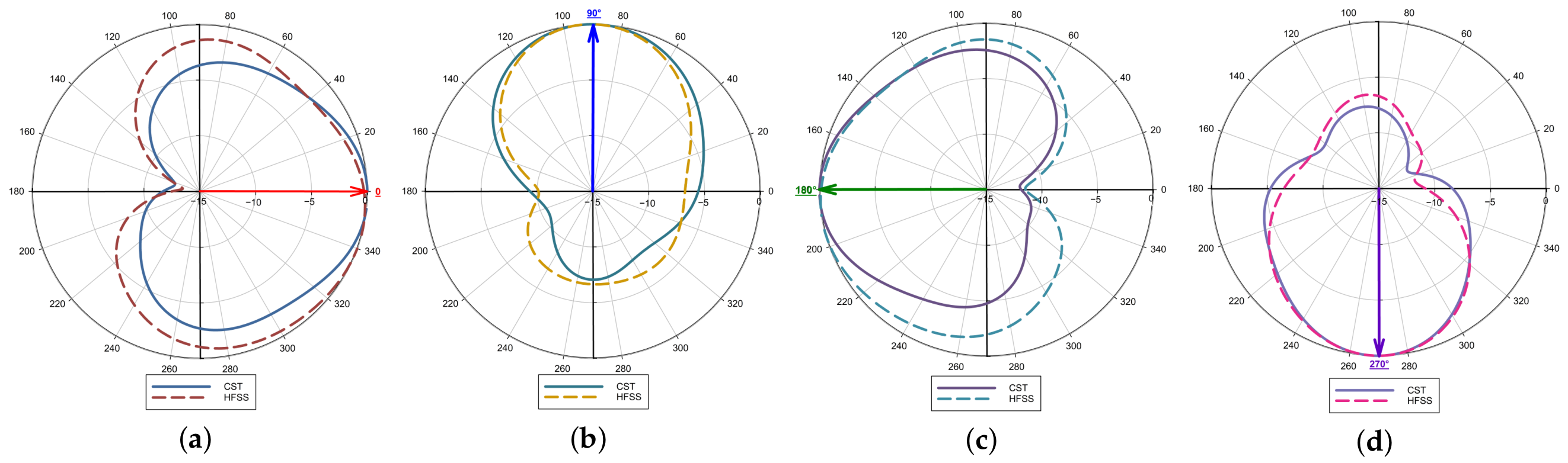
In addition to elevation-plane steering, the azimuth-plane radiation characteristics are investigated to demonstrate the full two-dimensional beam-steering capability of the proposed antenna. A key finding of this study is the antenna’s successful reconfigurability and precise beam steering in the azimuth plane. The simulation results, presented in Figure 12a–d, demonstrate clearly that the direction of the main lobe is directly and predictably controlled by the metasurface’s rotation angle. As the metasurface is rotated, the main lobe’s direction follows its angular displacement, with the lobe being directed at 0 , 90 , 180 , and 270 for corresponding metasurface rotation angles of 0 , 90 , 180 , and 270 , respectively. This direct and consistent relationship between the physical rotation of the metasurface and the resulting beam direction represents an effective and reliable mechanism for dynamic beam steering. This achievement highlights the simplicity and reliability of the proposed design, positioning it as a promising solution for future wireless communication systems and phased-array applications that demand agile and reliable beam control.
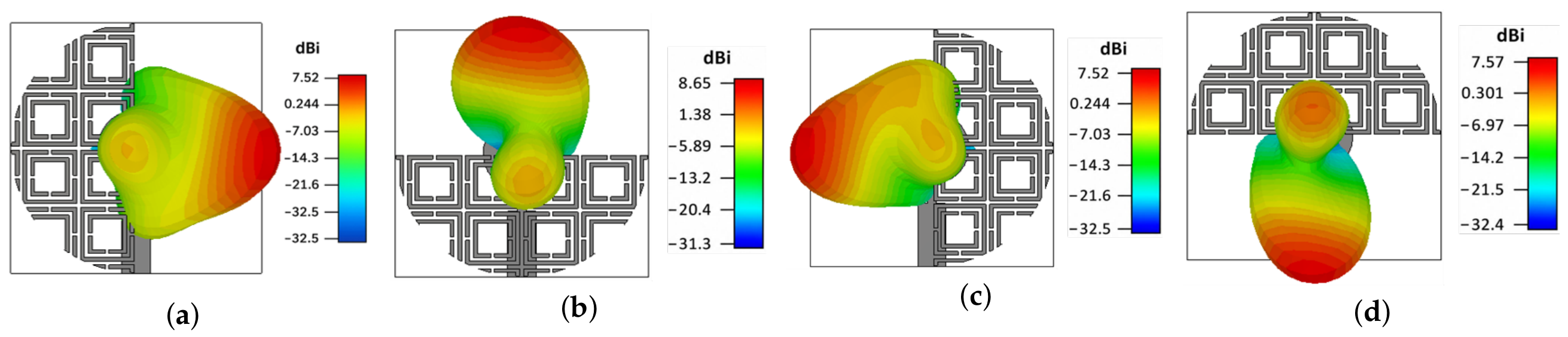
To evaluate the performance of the proposed antenna, the simulated 3D radiation patterns for the four rotation states are presented in Figure 13a–d. Here, a linear scaling is adopted for the 3D plots to clearly show the sharp directive beams and highlight the beam-steering capability. It can be observed that the main lobe direction systematically points toward the opposite side of the metasurface location, which acts as a reflective boundary.
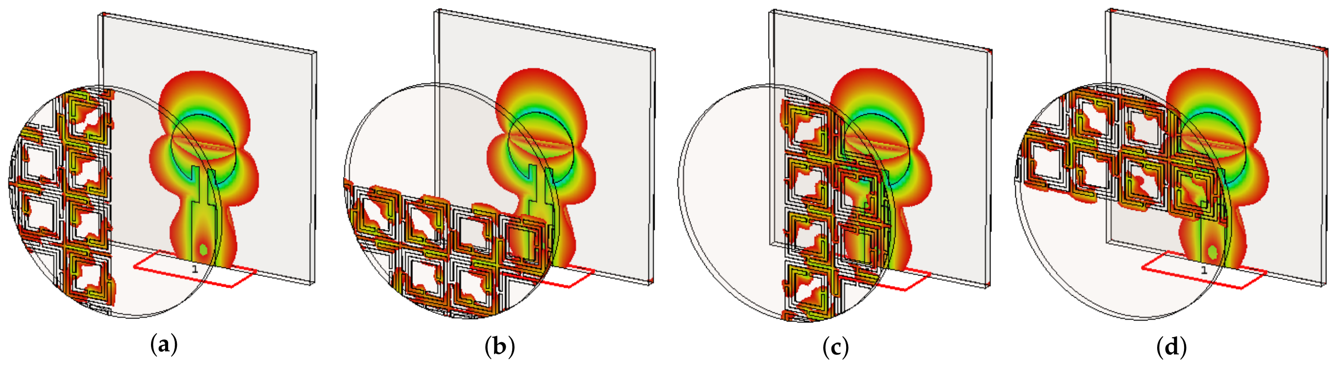
To further confirm this operating mechanism, the near-field E-field distributions are investigated and illustrated in Figure 14a–d. When the radiated wave encounters the metasurface, the electric field becomes strongly concentrated in the region covered by its unit cells, while the uncovered side exhibits a significantly weaker field. This asymmetric near-field distribution confirms that the mechanical rotation of the metasurface modifies the local phase and E-field distribution above the antenna aperture, which in turn controls the direction of the radiated energy toward the opposite side. Consequently, the near-field E-field maps shown in Figure 14 are in strong agreement with the 3D far-field radiation characteristics presented in Figure 13. In all cases, the main lobe systematically aligns with the region of maximum E-field concentration introduced by the metasurface rotation.
Table 3 summarizes the radiation characteristics across the four steering states. The antenna maintains a stable peak gain (7.54–8.66 dBi), confirming the robustness of the rotation-based steering mechanism. While the side lobe levels S L L (−7.1 to −7.5 dB) and front-to-back ratios F B R (7–12 dB) are relatively moderate, these values are inherent to the structural asymmetry of the half-loaded metasurface. This configuration prioritizes system simplicity and mechanical reconfigurability over complex phase-compensation networks found in conventional phased arrays. The observed radiation patterns are physically consistent with the diffraction effects at the metasurface interfaces and the finite separation distance, offering a low-complexity alternative for 5G beam-steering applications.
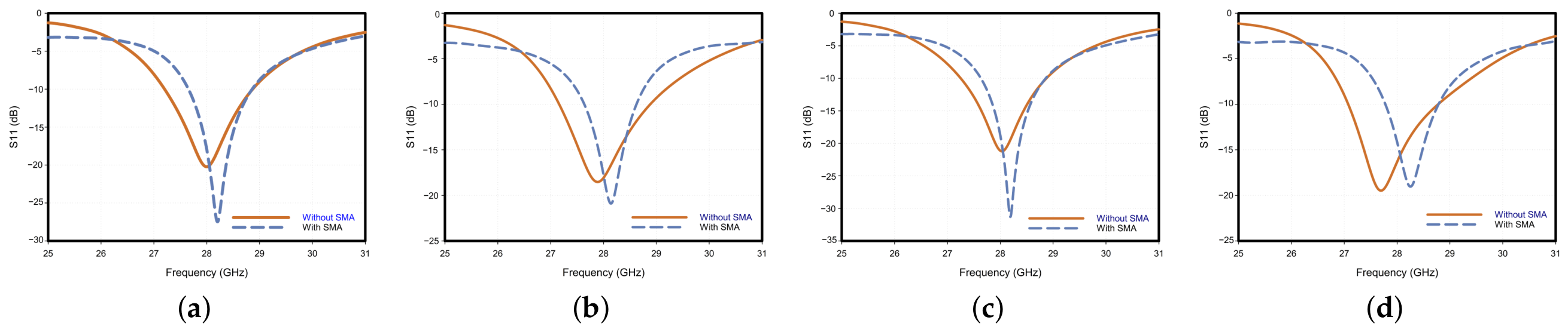
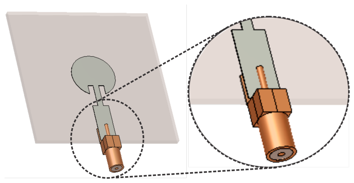
To ensure the practical feasibility of the proposed antenna, we evaluated its performance after integrating the physical model of the SMA connector into the full-wave simulation. Figure 15 details the integration of the SMA connector and its exact position. Furthermore, Figure 16a–d present a comparison of the reflection coefficient ( S 11 ) for the antenna with and without the SMA connector across all four reconfigurable states shown in Figure 10. The simulation results demonstrate that the antenna consistently maintains its operational performance across all states. In all cases, the reflection coefficient remains below 10 dB within the target frequency band. A slight shift in the resonant frequency is observed in some states, which is attributed to the capacitive loading effect introduced by the physical structure of the SMA connector. This analysis validates that the proposed design maintains its intended characteristics under realistic implementation conditions.
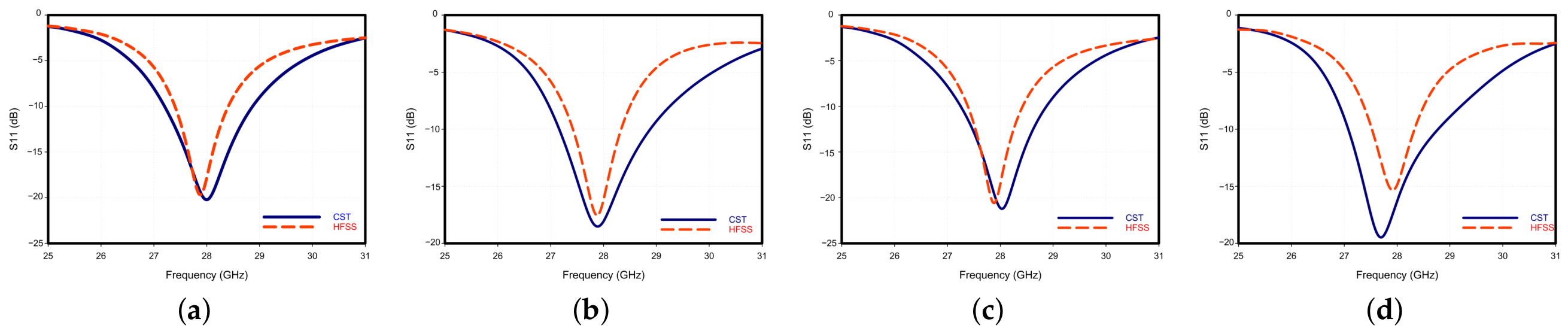
To further validate the reliability and robustness of the proposed reconfigurable antenna, a cross-validation study was carried out using ANSYS HFSS 2024 R1 in addition to CST Microwave Studio. The previously presented two-dimensional radiation patterns in the elevation plane, shown in Figure 11a–d, and in the azimuth plane, shown in Figure 12a–d, exhibit very good agreement between the two full-wave electromagnetic solvers for all four metasurface rotation states. This strong consistency confirms the predicted beam-steering behavior and indicates that the radiation characteristics of the antenna are physically meaningful and independent of the numerical solver employed. In addition to radiation pattern validation, the reflection coefficient was examined to provide further confirmation of the antenna performance. As illustrated in Figure 17a–d, the reflection coefficient responses obtained from both CST and HFSS for the four selected rotation states show close agreement in terms of resonant frequency and impedance matching bandwidth. This consistency further demonstrates the robustness of the proposed design and reinforces the credibility of the full-wave simulation results.
Table 4 presents a comparative performance analysis. The results indicate that the proposed design achieves a favorable trade-off. To ensure a fair and standardized comparison across different operating frequencies, the electrical size in the table is calculated by normalizing the total physical dimensions ( W × W × H t o t a l ) to the free-space wavelength ( λ 0 ) at the operating frequency. Specifically, our approach demonstrates distinctive novelty by offering the highest radiation efficiency ( 94 % ) at 28 GHz among all referenced works, including the highest gain density for its compact size ( 1.25 × 1.25 × 0.98 λ 0 3 ). While other reported designs either lack reconfigurability or exhibit much lower efficiency, our antenna maintains this exceptional performance. With four distinct beam directions through simple physical rotation of the metasurface, there is a clear relationship between the rotation angle and the main-lobe direction. Consequently, this established approach provides a practical and reliable solution for beam-steering applications requiring both compact size and low system complexity.
  • Limitations and Research Perspectives
    While the proposed reconfigurable antenna demonstrates high performance and robust beam-steering capabilities, the authors acknowledge the absence of experimental measurements as a limitation of the current study. This constraint is primarily due to the current lack of specialized millimeter-wave measurement facilities at our institution. However, to ensure the highest possible technical rigor and the physical validity of the reported metrics, a rigorous double-solver cross-validation strategy was implemented. The very good agreement observed between the Finite Integration Technique (FIT) in CST and the Finite Element Method (FEM) in ANSYS HFSS across all four rotation states provides strong evidence that the results are physically meaningful and independent of numerical artifacts.
    Furthermore, the integration of a realistic physical model of a commercial SMA connector allowed for the characterization of the design under practical loading conditions, accounting for dielectric losses and capacitive effects that are often neglected in purely theoretical works. Future research will focus on the fabrication of a physical prototype and its characterization in a controlled environment to evaluate real-world factors such as fabrication tolerances and mechanical alignment precision.

4. Conclusions

Patch antennas have emerged as one of the most promising candidates for fifth-generation (5G) communication systems in the millimeter-wave (mmWave) band, primarily due to their ease of fabrication and seamless integration into modern devices. However, their inherent limitations, including narrow operational bandwidth and static radiation characteristics, significantly hinder their full potential. To address these challenges, reconfigurable antenna technologies have become a critical area of research, enabling dynamic control over radiation behavior.
In this work, the effectiveness of integrating a mechanically reconfigurable metasurface has been successfully demonstrated as a robust solution to these limitations. The proposed design overcomes the fixed radiation characteristics of the conventional patch antenna and enables controlled beam steering. A key contribution of this study is the establishment of a direct and highly predictable relationship between the physical rotation angle of the metasurface and the resulting main-lobe direction. This behavior allows the antenna beam to be accurately steered toward desired directions, which is essential for adaptive wireless communication systems.
Furthermore, the simplicity of the proposed mechanical reconfiguration mechanism, combined with its compact structure and stable radiation performance, makes the design both practical and scalable. These features distinguish the proposed antenna from many existing reconfigurable solutions that rely on complex biasing networks or active components. Looking ahead, this work provides a strong foundation for future research toward intelligent and autonomous beam-steering systems. Integrating smart control algorithms capable of automatically selecting the optimal metasurface rotation angle based on the surrounding signal environment could transform the proposed design into a fully adaptive antenna platform. Such advancements would significantly enhance real-time communication reliability and efficiency in next-generation wireless networks.

Author Contributions

Conceptualization, Y.E.M., S.A. and A.K.; methodology, Y.E.M., F.R. and A.K.; software, Y.E.M. and F.R.; validation, Y.E.M., S.A. and A.K.; investigation, Y.E.M. and A.K.; writing—original draft preparation, Y.E.M.; writing—review and editing, S.A. and A.K.; supervision, S.A. and A.K. All authors have read and agreed to the published version of the manuscript.

Funding

This research received no external funding.

Institutional Review Board Statement

Not applicable.

Informed Consent Statement

Not applicable.

Data Availability Statement

The data presented in the study are available in the article.

Acknowledgments

During the preparation of this work, the authors used generative AI-based language editing tools (specifically Gemini 3.1 Pro and Claude Pro, https://claude.ai, accessed on 23 June 2026) exclusively for grammatical and spelling corrections to improve the clarity of the manuscript. The authors have reviewed and edited the output and take full responsibility for the content of this publication.

Conflicts of Interest

The authors declare no conflicts of interest.

References

  1. Bukhari, S.S.; Vardaxoglou, J.; Whittow, W. A metasurfaces review: Definitions and applications. Appl. Sci. 2019, 9, 2727. [Google Scholar] [CrossRef]
  2. Thenkumari, K.; Sankaran, K.S.; Mathana, J. Design and implementation of frequency reconfigurable antenna for Wi-Fi applications. Eng. Sci. 2023, 23, 876. [Google Scholar]
  3. Ullah, S.; Ullah, S.; Ahmad, I.; Khan, W.U.R.; Ahmad, T.; Habib, U.; Albreem, M.A.; Alsharif, M.H.; Uthansakul, P. Frequency Reconfigurable Antenna for Portable Wireless Applications. Comput. Mater. Contin. 2021, 68, 3015. [Google Scholar] [CrossRef]
  4. Fan, Y.; Li, R.; Cui, Y. Development of polarisation reconfigurable omnidirectional antennas using crossed dipoles. IET Microw. Antennas Propag. 2019, 13, 485–491. [Google Scholar] [CrossRef]
  5. Cui, Y.; Zhang, P.; Li, R. Broadband quad-polarisation reconfigurable antenna. Electron. Lett. 2018, 54, 1199–1200. [Google Scholar]
  6. Zhao, S.; Wang, Z.; Dong, Y. A planar pattern-reconfigurable antenna with stable radiation performance. IEEE Antennas Wirel. Propag. Lett. 2022, 21, 784–788. [Google Scholar] [CrossRef]
  7. Gao, F.; Sun, H. A radiation-pattern reconfigurable antenna array for vehicular communications. Sensors 2024, 24, 4136. [Google Scholar] [CrossRef] [PubMed]
  8. El maimouni, Y.; Ahyoud, S.; Kaabal, A. Mechanical Reconfiguration of Circular Patch Antenna Using Metasurface for 5G Wireless Communications. In Proceedings of the International Conference on Electrical Systems & Automation; Springer: Cham, Switzerland, 2023; pp. 277–283. [Google Scholar]
  9. Rahmani, F.; Amar Touhami, N.; Belbachir Kchairi, A.; Aknin, N.; Taher, N. Pattern Reconfigurable Antenna for VANET, Wi-Fi, and WiMAX Wireless Communication Systems. Int. J. Antennas Propag. 2021, 2021, 9973839. [Google Scholar]
  10. Liu, X.; Leung, K.W.; Yang, N. A pattern-reconfigurable cylindrical dielectric resonator antenna with three switchable radiation patterns. IEEE Trans. Antennas Propag. 2023, 71, 3997–4006. [Google Scholar] [CrossRef]
  11. Mahlaoui, Z.; Antonino-Daviu, E.; Ferrando-Bataller, M. Radiation pattern reconfigurable antenna for IoT devices. Int. J. Antennas Propag. 2021, 2021, 5534063. [Google Scholar] [CrossRef]
  12. Ali, A.; Mitra, A.; Aïssa, B. Metamaterials and metasurfaces: A review from the perspectives of materials, mechanisms and advanced metadevices. Nanomaterials 2022, 12, 1027. [Google Scholar] [CrossRef] [PubMed]
  13. Jarchi, S. Radiation pattern direction control of THz antenna with applying planar graphene metasurface. Optik 2021, 243, 167458. [Google Scholar] [CrossRef]
  14. Taghvaee, H.; Abadal, S.; Pitilakis, A.; Tsilipakos, O.; Tasolamprou, A.; Liaskos, C.K.; Kafesaki, M.; Kantartzis, N.V.; Cabellos-Aparicio, A.; Alarcón, E. Scalability analysis of programmable metasurfaces for beam steering. arXiv 2020, arXiv:2004.06917. [Google Scholar]
  15. Chen, A.; Ning, X. A pattern and polarization reconfigurable antenna with metasurface. Int. J. RF Microw. Comput.-Aided Eng. 2021, 31, e22312. [Google Scholar]
  16. Li, W.; Wang, Y.M.; Hei, Y.; Li, B.; Shi, X. A compact low-profile reconfigurable metasurface antenna with polarization and pattern diversities. IEEE Antennas Wirel. Propag. Lett. 2021, 20, 1170–1174. [Google Scholar] [CrossRef]
  17. Nasr, A.M.; Sarabandi, K. A low-cost millimeter-wave 5G V2X multi-beam dual-polarized windshield antenna. IEEE Open J. Antennas Propag. 2022, 3, 1313–1323. [Google Scholar]
  18. Rahmani, F.; Belbachir Kchairi, A.; El Bakkali, M.; Taher, N.; Amar Touhami, N.; Elhamadi, T.E. Sub-6 GHz reconfigurable beam-switched circular antenna for wireless networks. Arab. J. Sci. Eng. 2025, 50, 5589–5602. [Google Scholar]
  19. Schmitt, L.; Liu, X.; Schmitt, P.; Czylwik, A.; Hoffmann, M. Large displacement actuators with multi-point stability for a MEMS-driven THz beam steering concept. J. Microelectromech. Syst. 2023, 32, 195–207. [Google Scholar]
  20. Zhang, Y.; Lin, S.; Yu, S.; Liu, G.J.; Denisov, A. Design and analysis of optically controlled pattern reconfigurable planar Yagi–Uda antenna. IET Microw. Antennas Propag. 2018, 12, 2053–2059. [Google Scholar] [CrossRef]
  21. Yang, X.; Xu, S.; Yang, F.; Li, M.; Hou, Y.; Jiang, S.; Liu, L. A broadband high-efficiency reconfigurable reflectarray antenna using mechanically rotational elements. IEEE Trans. Antennas Propag. 2017, 65, 3959–3966. [Google Scholar] [CrossRef]
  22. Rahmani, F.; El Bakkali, M.; Dkiouak, A.; Touhami, N.A.; Belbachir Kchairi, A.; Samoudi, B.; Canale, L. A High-Gain Reconfigurable Beam-Switched Circular Array Antenna Based on Pentagonal Radiating Elements Fed by Mutual Coupling for Sub-6 GHz Wireless Application Systems. Electronics 2025, 14, 3701. [Google Scholar]
  23. Ibrahim, A.A.; Ali, W.A.; Alathbah, M.; Sabek, A.R. Four-port 38 GHz MIMO antenna with high gain and isolation for 5G wireless networks. Sensors 2023, 23, 3557. [Google Scholar] [CrossRef] [PubMed]
  24. Farahat, A.E.; Hussein, K.F. Dual-band (28/38 GHz) wideband MIMO antenna for 5G mobile applications. IEEE Access 2022, 10, 32213–32223. [Google Scholar] [CrossRef]
  25. Zhang, Y.; Deng, J.Y.; Li, M.J.; Sun, D.; Guo, L.X. A MIMO dielectric resonator antenna with improved isolation for 5G mm-wave applications. IEEE Antennas Wirel. Propag. Lett. 2019, 18, 747–751. [Google Scholar] [CrossRef]
  26. Ali Esmail, B.; Majid, H.A.; Zainal Abidin, Z.; Haimi Dahlan, S.; Himdi, M.; Dewan, R.; Kamal A Rahim, M.; Al-Fadhali, N. Reconfigurable radiation pattern of planar antenna using metamaterial for 5G applications. Materials 2020, 13, 582. [Google Scholar] [CrossRef] [PubMed]
  27. Fan, C.; Wu, B.; Hu, Y.; Zhao, Y.; Su, T. Millimeter-wave pattern reconfigurable Vivaldi antenna using tunable resistor based on graphene. IEEE Trans. Antennas Propag. 2019, 68, 4939–4943. [Google Scholar] [CrossRef]
  28. Arshad, F.; Khan, Z.U.; Ali, A.; Amin, Y.; Tenhunen, H. Compact beam-switchable antenna for mm-wave 5G handheld devices. IET Microw. Antennas Propag. 2021, 15, 778–787. [Google Scholar]
  29. Darvazehban, A.; Rezaeieh, S.A.; Abbosh, A.M. Programmable metasurface antenna for electromagnetic torso scanning. IEEE Access 2020, 8, 166801–166812. [Google Scholar] [CrossRef]
Figure 1. Proposed antenna after the addition of the metasurfaces.
Telecom 07 00087 g001
Figure 2. Geometries of proposed antenna.
Telecom 07 00087 g002
Figure 3. Simulation results of the effect of parameter a: (a) reflection coefficient; (b) gain.
Telecom 07 00087 g003
Figure 4. Simulation results of the effect of parameter b: (a) Reflection Coefficient. (b) gain.
Telecom 07 00087 g004
Figure 5. Simulation results of the effect of parameter R p : (a) reflection coefficient; (b) gain.
Telecom 07 00087 g005
Figure 6. (a) Geometry of the proposed unit cell. (b) CST Model of the proposed unit cell. (c) Simulated S-Parameters of the unit cell.
Telecom 07 00087 g006
Figure 7. Influence of the metasurface height (Z) on the antenna performance: (a) reflection coefficient ( S 11 ), (b) realized gain, (c) total efficiency.
Telecom 07 00087 g007
Figure 8. (a) Reflection coefficient without and with SRRs. (b) Efficiency without and with SRR.
Telecom 07 00087 g008
Figure 9. 2D radiation patterns of antenna without SRR: (a) Elevation plane. (b) Azimuth plane.
Telecom 07 00087 g009
Figure 10. Configurations of the proposed antenna for different metasurface rotation states: (a) State 1. (b) State 2. (c) State 3. (d) State 4.
Telecom 07 00087 g010
Figure 11. Elevation-plane radiation patterns illustrating beam steering for four different metasurface rotation states, obtained using CST and HFSS (a) State 1. (b) State 2. (c) State 3. (d) State 4.
Telecom 07 00087 g011
Figure 12. Azimuth-plane radiation patterns illustrating beam steering for four different metasurface rotation states, obtained using CST and HFSS (a) State 1. (b) State 2. (c) State 3. (d) State 4.
Telecom 07 00087 g012
Figure 13. 3D Far-Field radiation patterns illustating beam steering for four different metasurface rotation states: (a) State 1. (b) State 2. (c) State 3. (d) State 4.
Telecom 07 00087 g013
Figure 14. E-Field distribution for four different metasurface rotation states: (a) State 1. (b) State 2. (c) State 3. (d) State 4.
Telecom 07 00087 g014
Figure 15. Integration of the SMA connector into the proposed reconfigurable antenna design.
Telecom 07 00087 g015
Figure 16. Simulated reflection coefficient comparison with and without the SMA connector for four different metasurface rotation states: (a) State 1. (b) State 2. (c) State 3. (d) State 4.
Telecom 07 00087 g016
Figure 17. Simulated reflection coefficient comparison between CST and HFSS for four different metasurface rotation states: (a) state 1. (b) state 2. (c) state 3. (d) state 4.
Telecom 07 00087 g017
Table 1. Dimensions of the patch antenna.
ParameterW R p ab W f
Value (mm) 13.44 2.05 0.5 1.1 1.52
Table 2. Dimensions of unit cell.
Parameterxpgs
Value (mm)3 0.17 0.2 0.2
Table 3. Radiation pattern analysis: SLL, FBR, angular width, and main beam direction for the steering states.
StatesSLL * (dB)FBR * (dB)Angular Width (3 dB)MBD * ( ϕ , θ )
State 1Merged12 165 ( 0 , 43 )
State 2 7.1 7.06 99.1 ( 90 , 41 )
State 3Merged 11.9 165.6 ( 180 , 44 )
State 4 7.5 7.85 99.6 ( 270 , 46 )
* SLL: Side Lobe Level, FBR: Front to Back Ratio, MBD: Main Beam Direction.
Table 4. Comparative performance analysis of the proposed reconfigurable antenna and recent works.
Ref f r (GHZ)BW (%)Max Gain (db)Efficiency (%)Recon.SubstratSize ( λ 0 3 )
[23]387.89 5.5 85NORogers RT 4003 3.28 × 3.28 × 0.03
[24]28 and 382.78 5.86 80 and 85 N O Rogers Ro3003 0.95 × 1.11 × 0.03
[25]284.648NGYESRogers RT5880 1.86 × 1.86 × 0.03
[26]28 5.9 NGYESRogers RT5880 3.6 × 5.6 × 0.2
[27]3016.6 3.8 40YESFR-4 3.2 × 0.8 × 0.05
[28] 28.55 10.68 8.9 NGYESRogers RT5870 1.9 × 1.9 × 0.076
[29] 1.05 28.5 9.4 NGYESFR-4 0.9 × 0.9 × 0.06
This Work286.07 8.66 94YESRogers RT5880 1.25 × 1.25 × 0.98
Disclaimer/Publisher’s Note: The statements, opinions and data contained in all publications are solely those of the individual author(s) and contributor(s) and not of MDPI and/or the editor(s). MDPI and/or the editor(s) disclaim responsibility for any injury to people or property resulting from any ideas, methods, instructions or products referred to in the content.