Article

Ultra-Thin Compact Bidirectional S-Slot Antenna for 5G Communications

1
Nanoelectronics Integrated Systems Center, School of Engineering and Applied Sciences, Nile University, Giza 12588, Egypt
2
Department of Electrical & Computer Engineering, McMaster University, Hamilton, ON L8S 4K1, Canada
3
Microstrip Circuits Department, Electronics Research Institute, New Nozha, Cairo 11843, Egypt
4
Physics Department, School of Sciences and Engineering, The American University in Cairo, New Cairo 11835, Egypt
*
Author to whom correspondence should be addressed.
Telecom 2026, 7(2), 46; https://doi.org/10.3390/telecom7020046
Submission received: 29 January 2026 / Revised: 1 March 2026 / Accepted: 26 March 2026 / Published: 20 April 2026

Abstract

A compact and low-profile S-slot antenna for millimeter-wave wireless communication applications is presented in this paper. The antenna employs an S-shaped slot etched within a ground plane and excited by a hook-shaped microstrip feeding line to radiate a linearly polarized wave with a bidirectional broadside radiation beam. The antenna geometrical parameters are optimized to cover the n257 and n261 5G bands of the 5G mobile communications. The proposed antenna is fabricated and measured. Simulated and measured results demonstrate good impedance matching, with a measured fractional bandwidth of 18.3% and a maximum realized gain of 4.8 dBi across the desired operating bandwidth for the S-slot antenna with extended ground plane necessary for the purpose of measurements. The performance remains largely unaffected when the ground plane is reduced, highlighting the antenna’s suitability for compact implementations. Consequently, the proposed antenna is well suited for indoor 5G small-cell deployments and future railway wireless communication systems. Moreover, it can serve as a unit element in MIMO arrays or larger antenna configurations. To further demonstrate scalability and system-level applicability, the antenna element is extended into a compact eight-element MIMO array providing dual linear polarization. The array exhibits low mutual coupling, an envelope correlation coefficient on the order of 10 3 , and a diversity gain approaching 10 dB. These results demonstrate highly independent radiation characteristics and reliable MIMO performance in multipath environments.

1. Introduction

Fifth-generation (5G) millimeter-wave (mmWave) frequency bands have attracted considerable attention due to their ability to support ultra-high data rates and large system capacity [1]. Consequently, 5G wireless technology has become the dominant standard in modern communication systems, enabling a wide range of indoor and outdoor applications [2]. Commonly utilized 5G New Radio (NR) mmWave bands include n257 (26.5–29.5 GHz), n258 (24.25–27.5 GHz), n261 (27.5–28.35 GHz), n259 (39.5–43.5 GHz), and n260 (37.0–40.0 GHz), which are widely allocated for 5G mmWave deployments [3].
These advancements in 5G technology have directly enabled the rapid growth of the Internet of Things (IoT), facilitating the interconnection of diverse systems through intelligent and efficient wireless links. Among these systems are ground-based train communications, including subways and underground mining environments. Such applications require low-profile antennas capable of supporting reliable communication along narrow and elongated propagation paths [4]. Within this context, the Future Railway Mobile Communication System (FRMCS) has emerged as a next-generation railway communication standard built upon 5G and beyond technologies. It aims to replace the legacy Global System for Mobile Communications—Railway (GSM-R) and meet the increasing performance demands of future railway communication systems [5,6].
For this application, bidirectional antennas are recommended, as they provide symmetric coverage in opposite directions. Existing solutions to realize bidirectional radiation can be broadly classified into two categories. The first category employs back-to-back end-fire antennas, in which two directive elements radiate in opposite directions. Typical implementations utilize Yagi–Uda [7] or Vivaldi antennas [8]. While effective, this approach results in a larger physical footprint at each node. The second category relies on bidirectional broadside antennas [9,10,11], which radiate in two opposite directions, enabling bidirectional coverage without duplicating antenna elements [12].
Representative implementations include slot-based and monopole-based antenna configurations [9,12]. For broad-area coverage, printed monopoles are commonly employed due to their quasi-omnidirectional radiation characteristics [13], whereas slot antennas primarily exhibit broadside radiation and offer greater flexibility in shaping the radiation pattern in compact planar implementations. While slot antennas are not inherently directive, they are well suited for applications that do not require high gain, such as compact 5G mmWave terminals, short-range wireless links, and access nodes. Higher gain can be achieved if required via arranging slot antenna elements into array configurations. Several antenna designs have been reported in the literature to address bidirectional radiation with moderate-gain requirements for 5G mmWave applications. For instance, Sharma et al. [14] reported a compact monopole antenna operating over the 24.25–29.5 GHz band. The proposed single element achieves a gain of 6.09 dBi with a footprint of approximately 8 mm × 8 mm. Another design employing a rotated feeding technique for monopole antennas is proposed in [15], where bidirectional circularly polarized radiation is demonstrated. Despite the extensive research on monopole antennas operating in the mmWave range [14,15,16,17], relatively few compact slot-based antennas with bidirectional radiation characteristics have been reported. This can be attributed to the electrically small size of such antennas, which becomes comparable to the dimensions of the feeding connectors, leading to an increase in the overall antenna footprint. For example, in [18], a dummy ground plane of dimensions 10 mm × 6 mm is added to the structure to accommodate the launcher connector needed for the mmWave experimental characterization. However, in practical implementations where there is no need for mounting connectors, the ground-plane size can be reduced provided that the antenna performance is not significantly degraded. Among the studies focusing on compact slot antennas for mmWave applications, ref. [19] presented a rectangular ring-slot antenna fed by a microstrip line with an overall size of 11 mm × 11 mm × 0.25 mm. The antenna supports dual-band operation covering the 26/28 GHz and 39 GHz bands, achieving maximum gains of 5.8 dBi and 6.4 dBi, respectively. In [20], a rectangular slot antenna with dimensions of 12 mm × 12 mm × 0.2 mm was implemented, achieving a maximum gain of 4.6 dBi over an operating band of 25.5–30 GHz. A smaller antenna structure of only 8 mm × 8 mm × 0.25 mm was presented in [21], where an elliptical slot antenna surrounded by a small finite ground plane provides a bandwidth covering 22.2–31.4 GHz with a maximum gain of 7 dBi.
In this paper, a new compact low-profile S-slot antenna with bidirectional radiation is presented. The influence of ground-plane reduction is assessed by comparing antenna performance with a full ground plane and a reduced ground surrounding the slot radiator. The results demonstrate that reducing the ground-plane dimensions from 22 mm × 13.7 mm to only 4.9 mm × 4.7 mm has a limited effect on both the impedance bandwidth and gain. This confirms the robustness of the proposed design while significantly reducing its size. Compared with other compact slot-based antennas [19,20,21], the proposed design achieves more than 64% footprint reduction. Thus, the antenna is well suited for mmWave applications requiring small-to-moderate gain, such as indoor 5G small-cell deployments [22], where wide coverage and a compact size are essential. Moreover, it can serve as a unit element in multiple-input multiple-output (MIMO) or phased-array configurations to achieve higher gain and enhanced spatial coverage. A dual-linearly polarized eight-element MIMO arrangement has also been investigated to further improve diversity and system capacity. The overall array footprint is only 39 mm × 9 mm, demonstrating the compactness of the proposed design.

2. Antenna Geometry and Operation

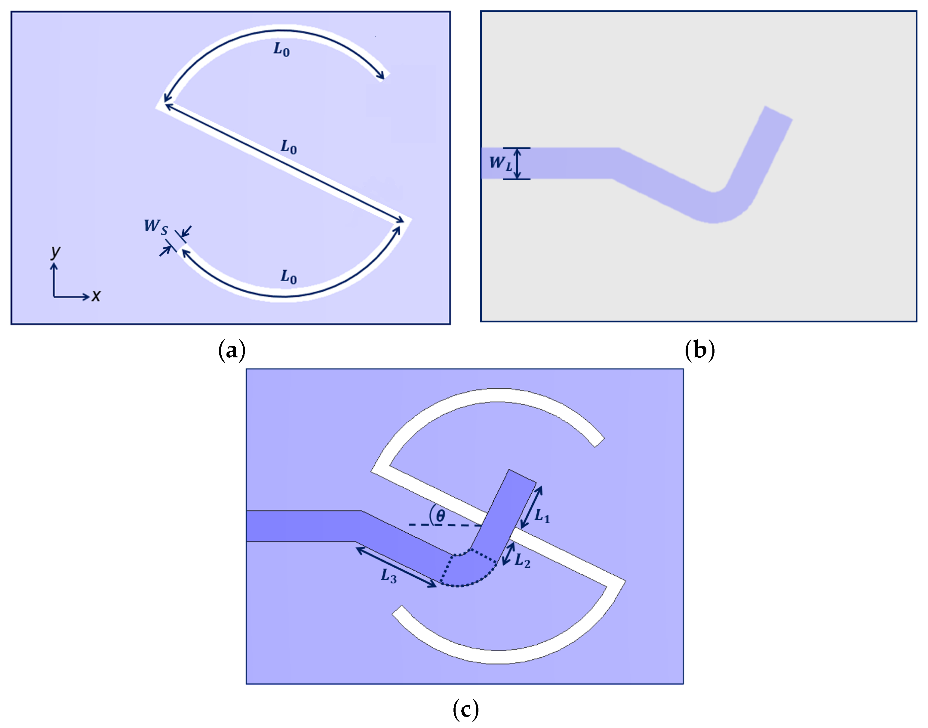
The structure of the proposed antenna is shown in Figure 1. It comprises an S-shaped slot radiator and a feeding microstrip line with a hook-shaped termination. The antenna is realized on a low-profile Rogers 4003C substrate with a thickness of 0.2 mm, a relative permittivity of 3.38, and a loss tangent of 0.0027 [23]. The S-slot is located on top of the substrate. It is formed from one straight segment and two circular segments. The total electrical length of the S-slot is 1.5 λ g , where λ g is the guided wavelength of the slot line forming the S-slot. In this way, the S-slot can be looked at as three half-wavelength dipoles. The way the circular segments of the S-slot are bent forces the equivalent magnetic current in the three segments to be in the same direction, leading to constructive interference of the radiated waves from the three segments.
The S-slot is coupled electromagnetically, through the substrate, to the feeding microstrip line located at the other side of the substrate. The feeding microstrip line consists of a horizontal portion terminated with a hook-shaped portion. The hook-shaped portion is comprised of parallel and perpendicular parts relative to the central segment of the S-slot. At the point of interaction, the central segment of the S-slot is oriented perpendicular to the feeding microstrip line to maximize the coupling between them. The symbolic dimensions of the proposed S-slot antenna are shown in Figure 1. These dimensions can be described as follows:
  • L 0 : length of each of the three segments forming the S-slot. The electrical value of this length should be close to 0.5 λ g . The optimum value of L 0 is 3.86 mm.
  • θ : rotation angle of the whole structure with respect to the horizontal direction. This rotation is applied to force the orientation of the electric field of the radiated wave to be parallel to the vertical edge of the substrate. In this way, the principal planes with the purest linear polarization become the x z - and y z -planes, which are the easiest planes for conducting radiation pattern measurements. After observing the cross-polarization level in all planar cuts perpendicular to the antenna with the best impedance matching spectrum, the value of this rotation angle should be 26 ° .
  • L 1 : length of the open circuit stub terminating the feeding microstrip line. The presence of this stub enhances the matching between the antenna and the feeding line. The optimum stub length is 0.72 mm.
  • L 2 : clearance length between the parallel part of the feeding microstrip line and the central segment of the S-slot. This clearance length should be adjusted such that the parallel microstrip line is sufficiently far from both the central segment and the lower circular segment of the S-slot. The optimum value of L 2 is 0.36 mm.
  • L 3 : the length of the parallel, to the central slot, portion of the feeding microstrip line. This portion is connected to the perpendicular portion through a right-angle curved bend with no sharp corners in order to eliminate parasitic radiation from corners. The value of L 3 depends on the values L 2 and θ . The calculated value of L 3 is 1.35 mm.
  • W S : width of the slot line forming the S-slot. This width controls the effective permittivity seen by the slot line; the wider the slot, the smaller the effective permittivity and the longer the guided wavelength. The optimum value of this parameter is 0.2 mm.
  • W L : width of the feeding microstrip line. This parameter is set to 0.45 mm, such that the characteristic impedance of the feeding microstrip line is 50 Ω .
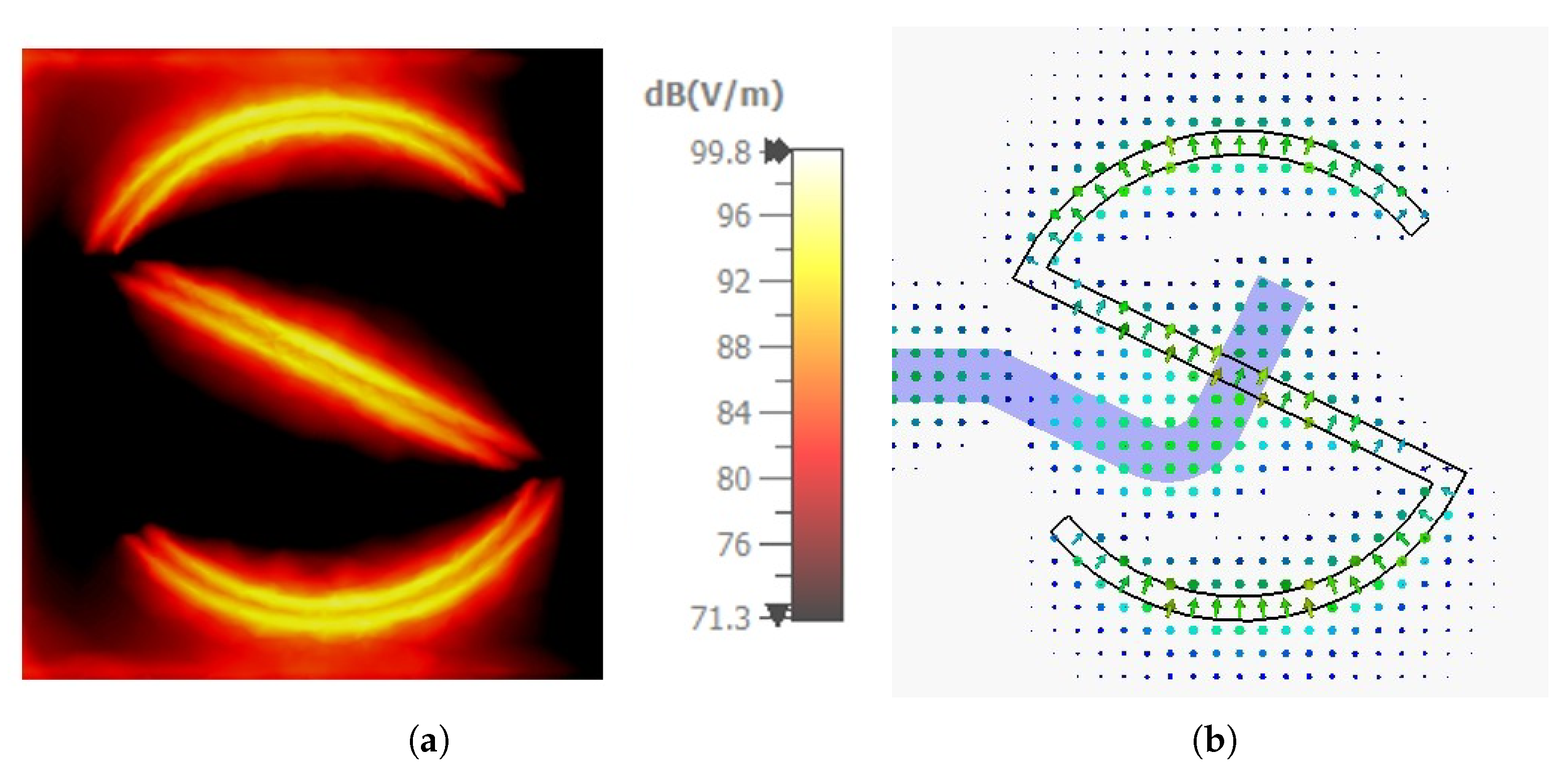
To illustrate the antenna operation, Figure 2 shows the electric field distribution along the central x y -plane of the S-slot at 28 GHz. All simulations in this paper are carried out using the frequency-domain solver of CST Microwave Studio. Tetrahedral mesh cells are used, which are best suited for structures with curved edges, such as the proposed structure. Adaptive mesh refinement is performed until convergence is reached. As shown in Figure 2a, each segment of the S-slot behaves as an equivalent magnetic dipole of approximately 0.5 λ g length, exhibiting a clear field null at its two ends and a maximum at its midpoint. Figure 2b demonstrates that the direction of the electric field is the same within the three segments of the S-slot, which leads to constructive interference of radiation along the broadside direction as desired.

3. Parametric Study

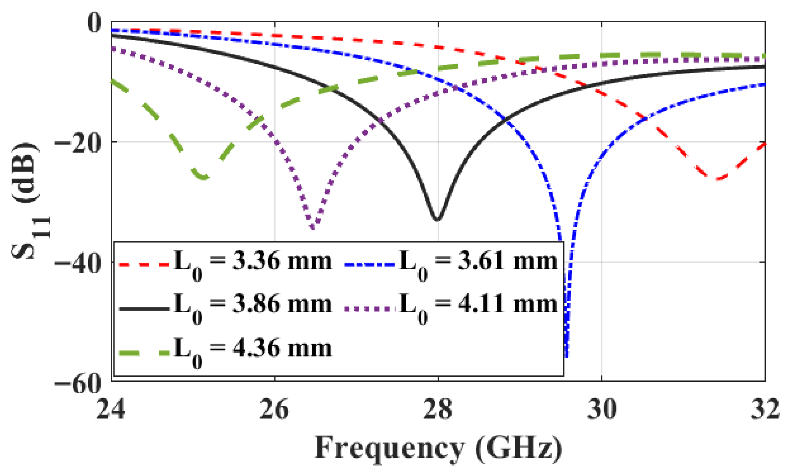
The optimum dimensions of the proposed S-slot antenna are: L 0 = 3.86 mm, L 1 = 0.72 mm, L 2 = 0.36 mm, L 3 = 1.35 mm, W S = 0.2 mm, W L = 0.45 mm, and θ = 26 ° . In this section, the impact of key geometric parameters on the antenna performance is investigated. These parameters are L 0 , L 1 , L 2 , and W S . First, the effect of varying the length of the three S-slot segments, L 0 , is examined, as illustrated in Figure 3. Increasing L 0 shifts the resonance towards a longer wavelength. Consequently, the antenna resonates at a lower frequency. This is because the resonance condition of a dipole with an equivalent magnetic current is L 0 = 0.5 ,   λ g = 0.5 ,   λ 0 / ε r , eff , where λ g , λ 0 , and ε r , eff denote the guided wavelength, free-space wavelength, and effective relative permittivity, respectively.
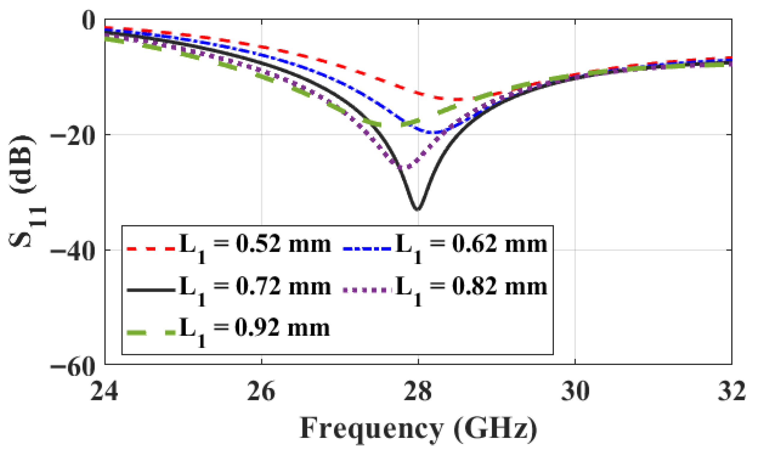
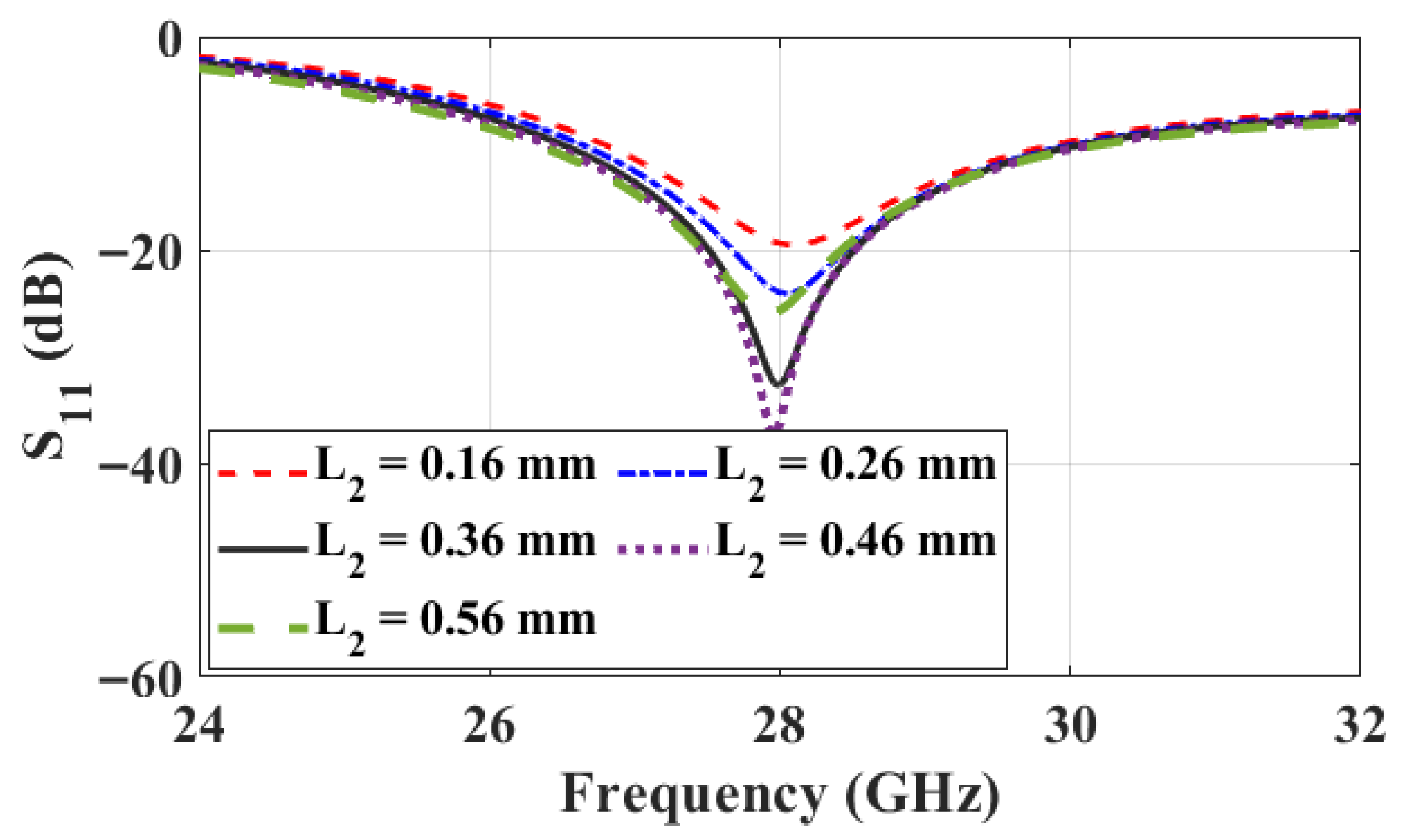
The second parameter, L 1 , represents the extension length of the microstrip line feeding the S-slot. This section behaves as an open-circuit impedance-matching stub and plays a crucial role in matching the antenna to the 50 Ω feed line. As shown in Figure 4, variations in L 1 significantly affect the matching level, indicating corresponding changes in the antenna input impedance. The parameter L 2 determines the relative positioning of the parallel part of the feeding microstrip line with length L 3 , with respect to the central and the lower segments of the S-slot. It also affects the value of the parameter L 3 since the angle θ is kept constant. For symmetric excitation, L 2 is chosen such that the parallel part of the feeding microstrip line is almost midway between the central segment and the edge of the lower segment of the S-slot. This way, the parallel part of the feeding line is as far as possible from the two slot segments simultaneously. Varying L 2 influences the impedance matching, as illustrated in Figure 5. This can be attributed to variations in the strength of the electromagnetic coupling between the parallel part of the feeding line and the two segments of the S-slot. The coupling strength changes as this part of the feeding line gets closer to either one of the two slot segments.
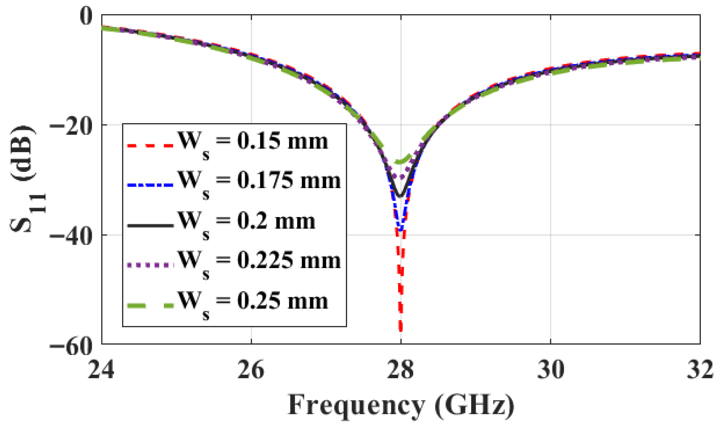
Finally, the effect of varying the S-slot width, W S , is investigated in Figure 6. Reducing the slot width increases the quality factor of the resonance curve, resulting in a sharper resonance and a slightly narrower bandwidth. Within the studied range, these variations are minor, allowing the slot width to be set to 0.2 mm as a practical compromise between the quality factor of the resonance and the fabrication feasibility.

4. Results and Discussion

4.1. Single Element

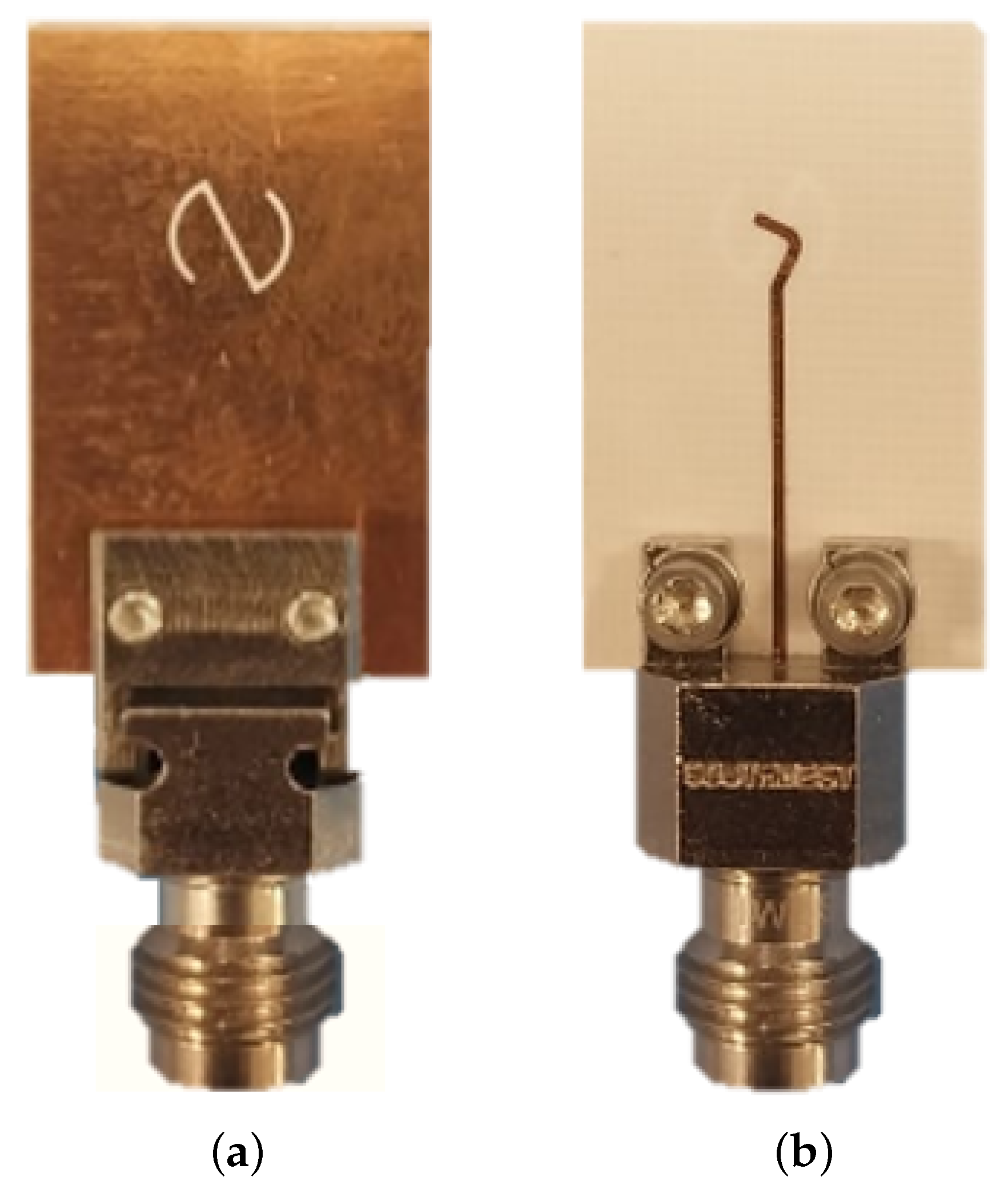
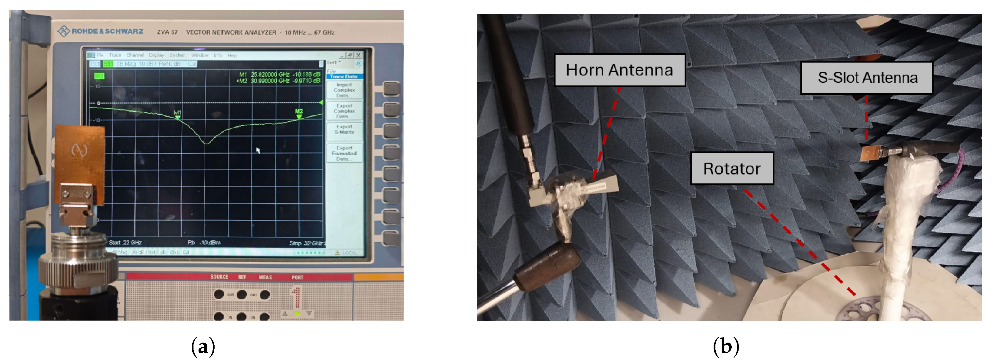
The antenna prototype was fabricated using standard PCB technology on a Rogers RO4003C substrate with a nominal dielectric constant of ε r = 3.38 . The dielectric constant tolerance ( ± 0.05 ) and substrate thickness tolerance may introduce minor variations in the performance [23]. At mmWave frequencies, antenna performance is influenced by fabrication tolerances and substrate parameter variations. However, these effects are generally within acceptable design margins when realistic manufacturing tolerances are considered. For commonly used substrates such as Rogers RO4003C, the typical PCB fabrication tolerances for thin high-frequency boards are on the order of ±0.003 in (≈±76 µm), and tighter controls of ±0.05 mm (50 µm) are commonly specified in high-speed and RF applications [24]. The fabricated prototype is shown in Figure 7. A SouthWest end-launch connector (model 1892-03A-9, Southwest Microwave, Inc., Tempe, AZ, USA) is used for feeding. The reflection coefficient, S 11 , is measured using a Rohde & Schwarz ZVA67 vector network analyzer (up to 67 GHz) to validate the operating bandwidth, as shown in Figure 8a. The radiation measurements are performed in an anechoic chamber, as shown in Figure 8b. Before conducting the measurements, the VNA was fully calibrated using a Short-Open-Load-Thru (SOLT) calibration kit. To obtain accurate gain measurements, a standard gain horn (model LB-28-10-C-KF; 26–40 GHz) is employed as a reference antenna. Owing to its well-characterized gain across the operating band, it enables reliable comparison with the antenna under test (AUT). During the measurement procedure, both the reference horn and the AUT were aligned under identical far-field conditions. The AUT gain was subsequently extracted using the standard gain-transfer technique, referring to the calibrated gain of the LB-28-10-C-KF horn.
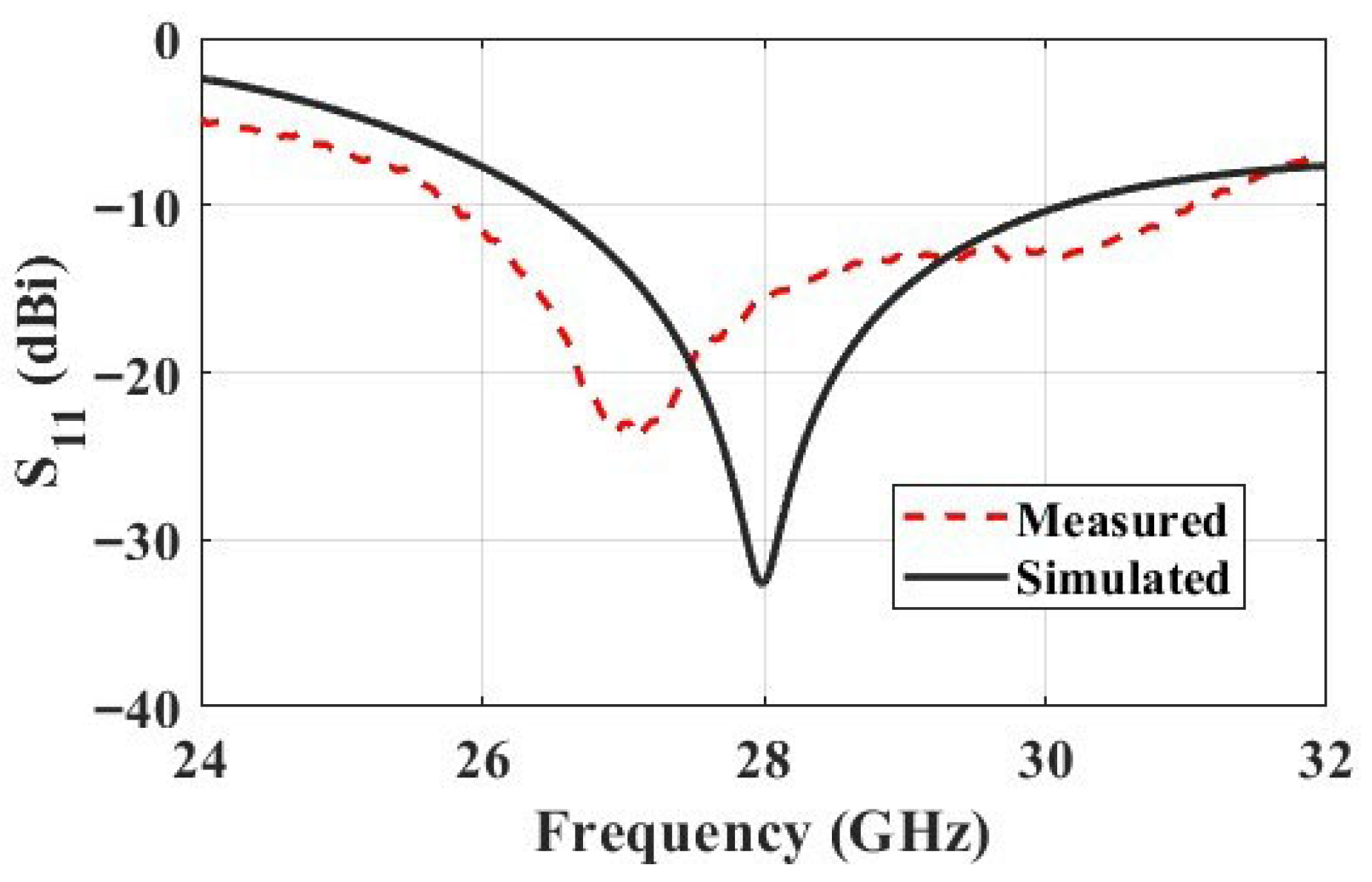
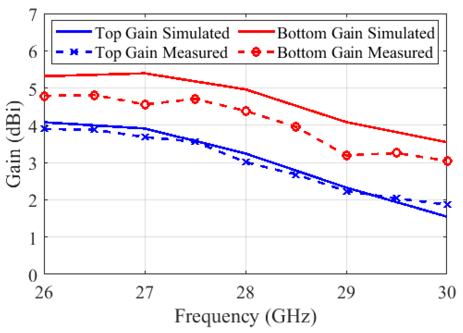
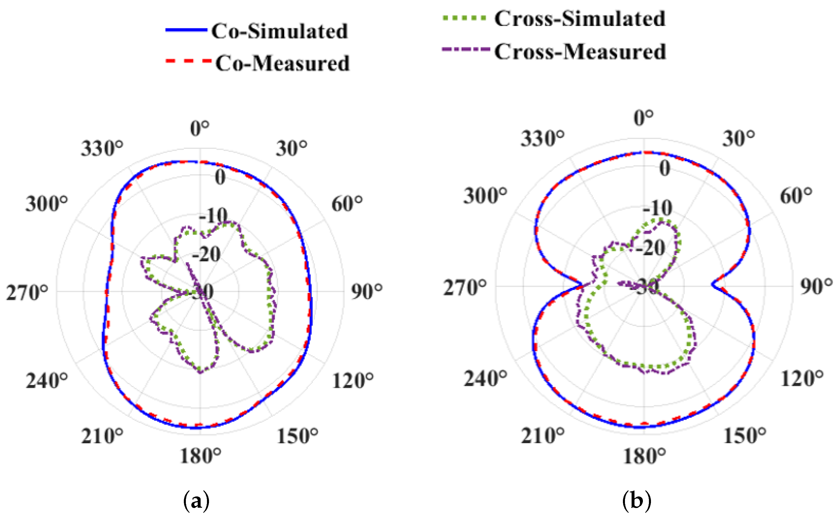
The simulated and measured reflection coefficient of the proposed antenna are plotted versus frequency in Figure 9. Based on the measurements, the antenna operates over the frequency range from 25.8 to 31 GHz, demonstrating good agreement with the simulation results obtained using CST. The measured fractional bandwidth of 18.3% is wider than the simulated value of 12.7% (26.5–30.1 GHz). Despite the acceptable difference between simulation and measurements, the proposed antenna successfully covers the n257 and n261 bands with a sufficiently low reflection coefficient. The discrepancy between simulation and measurements is mainly attributed to the electrically large end-launch connector whose dimensions are bigger than those of the antenna. The measured and simulated broadside gains in the top and bottom sides of the substrate are shown in Figure 10, exhibiting acceptable agreement. The maximum measured gains along the top and bottom sides are 3.9 and 4.8 dBi, respectively. The higher gain on the bottom side is attributed to the improved radiation matching towards the substrate side with higher permittivity than air. The simulated and measured 2D radiation patterns of the proposed antenna at 28 GHz are shown in Figure 11 along both the H- ( x z ) - and E- ( y z ) - principal planes. The measured patterns clearly show excellent agreement with the CST simulation results. The antenna exhibits bidirectional broadside radiation along the ± z -axis with slightly stronger radiation along the backside. Table 1 summarizes the key performance metrics of the proposed S-slot antenna. Two versions are considered: a full ground-plane prototype, which ensures sufficient separation from the connector and minimizes its parasitic effects, and a compact version with a reduced ground plane size, simulated in CST. Reducing the footprint from 2.638 λ 2 to 0.202 λ 2 results in only a slight performance variation, with the peak gain changing from 4.8 dBi to 4.16 dBi and the bandwidth remaining high, varying from 18.3% to 13.9%. Thus, the proposed antenna is characterized by its compact size with quasi-stable performance, even with a dramatic reduction in the ground-plane size. This advantage becomes particularly significant for multi-element implementations, such as antenna arrays and MIMO configurations, as will be discussed in Section 4.2.
To assess the performance of the proposed S-slot antenna, Table 2 provides a comparison with mmWave bidirectional antennas reported in the literature, summarizing their physical sizes and radiation performances. The proposed antenna is listed in two rows: the first for the fabricated full-size prototype and the second for the simulated reduced-ground-plane version. As demonstrated in Table 2, the proposed antenna with reduced ground-plane size exhibits the smallest effective footprint among the compared structures with an overall size 0.46 λ × 0.44 λ × 0.019 λ . This corresponds to less than one-third of the size of the compact antennas presented in [14,17,19,20,21,25]. Despite its small footprint, the antenna achieves a moderate gain of 4.16 dBi, making it suitable for mmWave applications which require a balance between size and radiation performance. In terms of bandwidth, the proposed S-slot antenna offers a fractional bandwidth of 13.9% covering the frequency range between 26.2 and 30 GHz, which falls within the mid-range of the reported designs. However, the achieved operating band fully covers the n257 and n261 bands and partially overlaps with the n258 band, thereby satisfying the bandwidth requirements of key 5G mmWave applications.

4.2. MIMO Array Configuration

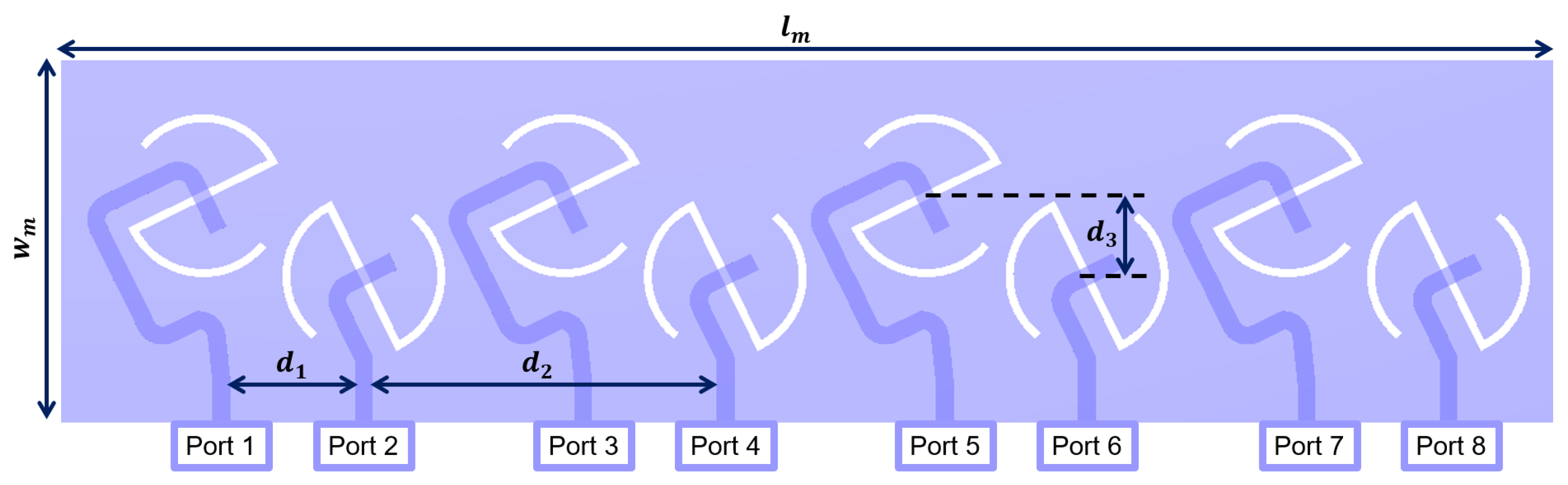
To enhance spatial coverage, channel capacity, and link reliability, the proposed S-slot antenna element is extended into a multi-port MIMO array configuration, as illustrated in Figure 12. The array consists of sequentially arranged bidirectional radiating elements printed on a common substrate with overall dimensions of l m = 39 mm and w m = 9 mm. The array comprises two element orientations, with four elements aligned along one polarization direction and four along the orthogonal direction. Each element is individually excited through dedicated ports, enabling simultaneous multi-channel transmission and reception. Adjacent elements are separated by a distance of d 1 = 3.5 mm and are alternately oriented to provide orthogonal linear polarization, while the spacing between elements with identical orientation is d 2 = 9 mm. These spacings are carefully selected to reduce mutual coupling while maintaining a compact footprint. In addition, a vertical offset of d 3 = 2 mm is introduced between adjacent elements to further suppress mutual coupling and reduce surface current interaction between neighboring radiators. The alternating orientation and offset placement provide polarization and spatial diversity, thereby reducing channel correlation. The proposed 1 × 8 MIMO array is well suited for railway and corridor environments, where the propagation channel is rich in multipath due to strong reflections from metallic walls, ceilings, and floors. Spatial separation along one axis produces distinct propagation paths, while orthogonal polarization diversity further decorrelates the received signals through polarization rotation caused by reflections.
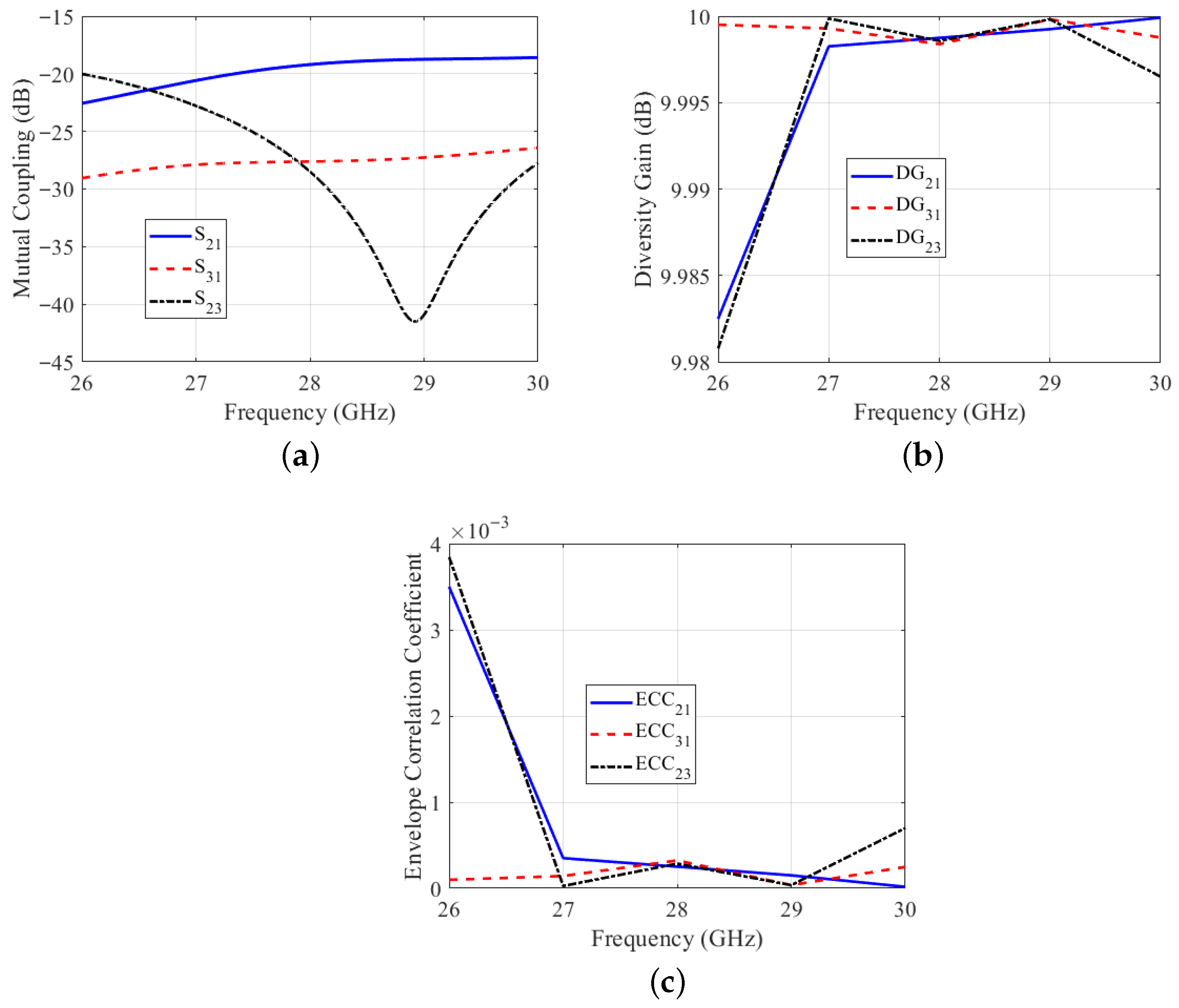
The MIMO performance of the proposed antenna is illustrated in Figure 13. As shown in Figure 13a, the mutual coupling between antenna elements remains sufficiently low across the operation band. The parameter | S 21 | is approximately 20 dB, | S 31 | stays below 27 dB, and | S 23 | drops below 40 dB near 29 GHz, confirming effective isolation. The corresponding diversity performance is presented in Figure 13b, where the diversity gain (DG) remains very close to the ideal value of 10 dB throughout the operating band. This metric measures the reliability improvement from diversity reception where values near 10 dB indicate nearly independent fading between antenna elements. Furthermore, Figure 13c shows the envelope correlation coefficient (ECC), which quantifies the similarity between the signals received by different antenna elements. The ECC remains on the order of 10 3 , indicating extremely low correlation and highly independent radiation characteristics. The slight increase near the lower band edge is attributed to minor pattern overlapping and coupling effects but remains negligible.

5. Conclusions

This paper presents a compact low-profile S-slot antenna for 5G mmWave applications. The antenna exhibits bidirectional, linearly polarized radiation along the broadside direction, making it suitable for indoor 5G small-cell deployments and short-range railway mobile communication systems. The proposed antenna provides wide impedance bandwidth covering the n257 and n261 bands and partially covering the n258 band, with good agreement between simulated and measured results. The antenna has also been investigated in an 8-element MIMO configuration, supporting two orthogonal linear polarizations. The arrangement of the MIMO elements ensures high isolation, and together with its low profile, wide bandwidth, and dual-polarization capability, this makes the system a practical and scalable solution for modern 5G mmWave applications.

Author Contributions

Conceptualization, E.A.S. and M.H.B.; Methodology, M.M.G. and E.A.S.; Investigation, M.M.G. and M.O.S.; Formal analysis, M.M.G., M.O.S. and E.A.S.; Validation, M.M.G. and A.M.A.; Writing—original draft, M.O.S., M.M.G. and A.M.A.; Writing—review and editing, M.O.S., M.M.G., E.A.S., A.M.A. and M.H.B. Project administration—E.A.S. All authors have read and agreed to the published version of the manuscript.

Funding

This research is supported by an internal research grant from The American University in Cairo.

Data Availability Statement

The original contributions presented in this study are included in this article. Further inquiries can be directed to the corresponding author.

Conflicts of Interest

The authors declare no conflicts of interest.

References

  1. Kumar, J.; Gupta, A.; Tanwar, S.; Khan, M.K. A Review on 5G and Beyond Wireless Communication Channel Models: Applications and Challenges. Phys. Commun. 2024, 67, 102488. [Google Scholar] [CrossRef] [Scilit]
  2. Gupta, A.; Vardhan, A.V.H.; Tanwar, S.; Kumar, N.; Singh, A. Performance Analysis at Different Millimetre-Wave Frequencies for Indoor Shopping Complex and Outdoor UAV Applications towards 5G. Microprocess. Microsyst. 2022, 90, 104506. [Google Scholar] [CrossRef] [Scilit]
  3. Nej, S.; Ghosh, A.; Ahmad, S.; Kumar, J.; Ghaffar, A.; Hussein, M.I. Design and Characterization of 10-Elements MIMO Antenna with Improved Isolation and Radiation Characteristics for mm-Wave 5G Applications. IEEE Access 2022, 10, 125086–125101. [Google Scholar] [CrossRef] [Scilit]
  4. Arya, A.K.; Kim, S.; Ko, K.; Kim, S. Antenna for IoT-Based Future Advanced (5G) Railway Communication with End-Fire Radiation. IEEE Internet Things J. 2022, 9, 7036–7042. [Google Scholar] [CrossRef] [Scilit]
  5. Carranza Ruiz de Loizaga, G.; Rada Martin, E. State of the Art of the Future Railway Mobile Communication System (FRMCS) Based on 5G Technology. Int. J. Sci. Acad. Res. 2024, 5, 7833–7840. [Google Scholar]
  6. Berbineau, M.; Sabra, A.; Pajusco, P.; Amghar, J.; D’Errico, R.; Sibel, J.C.; Corre, Y.; Guillemaut, S. 5G Realistic Radio Channel Models for FRMCS Deployment in Railway Environments. In Transport Transitions: Advancing Sustainable and Inclusive Mobility, Proceedings of the 10th TRA Conference, Dublin, Ireland, 15-18 April 2024; Springer: Cham, Switzerland, 2024; pp. 559–564. [Google Scholar]
  7. Hao, J.; Ren, J.; Du, X.; Mikkelsen, J.H.; Shen, M.; Yin, Y.Z. Pattern-Reconfigurable Yagi–Uda Antenna Based on Liquid Metal. IEEE Antennas Wirel. Propag. Lett. 2021, 20, 587–591. [Google Scholar] [CrossRef] [Scilit]
  8. Xie, J.; Chen, C.; He, J.; Qiao, H.; Fang, X.; Qu, T.; An, J. A Bidirectional Bent Vivaldi Connected Array with Short-Circuited Branches for UWB Pulse Radiation. IEEE Trans. Antennas Propag. 2024, 72, 9177–9187. [Google Scholar] [CrossRef] [Scilit]
  9. Lamultree, S.; Thanamalapong, W.; Dentri, S.; Phongcharoenpanich, C. Tri-Band Bidirectional Antenna for 2.4/5 GHz WLAN and Ku-Band Applications. Appl. Sci. 2022, 12, 5817. [Google Scholar] [CrossRef] [Scilit]
  10. Sallam, M.O.; Kandil, S.M.; Volski, V.; Vandenbosch, G.A.; Gad, M.M.; Soliman, E.A. High-Gain Ultrawideband CPW-Fed Crescent Slot Antenna for Next-Generation Wireless Systems. J. Electromagn. Waves Appl. 2025, 39, 1417–1429. [Google Scholar] [CrossRef] [Scilit]
  11. Yadav, M.V.; Kumar, R.C.; Yadav, S.V.; Ali, T.; Anguera, J. A Miniaturized Antenna for Millimeter-Wave 5G-II Band Communication. Technologies 2024, 12, 10. [Google Scholar] [CrossRef] [Scilit]
  12. Hou, Y.; Fu, Z.; Liu, M. A Compact High-Gain Slot Antenna Array with a Bidirectional Broadside Radiation Pattern. Electron. Lett. 2024, 60, e13078. [Google Scholar] [CrossRef] [Scilit]
  13. Ding, A.; Gan, T.H.; Shen, Z. Design of a Compact and Wideband Printed Monopole Antenna With Stable Omnidirectional Radiation Patterns. IEEE Antennas Wirel. Propag. Lett. 2024, 23, 1483–1487. [Google Scholar] [CrossRef] [Scilit]
  14. Sharma, A.; Sharma, S.; Sharma, V.; Wadhwa, G.; Kumar, R. A Compact Ultra-Wideband Millimeter-Wave Four-Port MIMO Antenna for 5G IoT Applications. Sensors 2024, 24, 7153. [Google Scholar] [CrossRef] [Scilit] [PubMed]
  15. Wang, C.; Xu, G.; Li, M.; Huang, Z.; Ren, X.; Wang, J.; Wu, X. Ultra-Wideband Millimeter-Wave Bidirectional Circularly Polarized Monopole Antenna Array. IEEE Trans. Antennas Propag. 2022, 71, 1117–1122. [Google Scholar] [CrossRef] [Scilit]
  16. Kumar, A.; Kumar, A. A Broadband Circularly Polarized Monopole Antenna for Millimeter-Wave Short-Range 5G Wireless Communication. Int. J. RF Microw. Comput.-Aided Eng. 2021, 31, e22518. [Google Scholar] [CrossRef] [Scilit]
  17. Ghouse, P.S.B.; Kumar, P.; Mane, P.R.; Pathan, S.; Ali, T.; Boulogeorgos, A.A.A.; Anguera, J. Dual-Band Antenna at 28 and 38 GHz Using Internal Stubs and Slot Perturbations. Technologies 2024, 12, 84. [Google Scholar] [CrossRef] [Scilit]
  18. Kim, J.H.; Choi, T.H.; Yoon, Y.J.; Kim, H. Compact Wide-Band Dual-Polarized Rectangular Slot Antenna for mm-Wave Communication. In Proceedings of the IEEE International Symposium on Antennas and Propagation (APSURSI), Montreal, QC, Canada, 5–10 July 2020; IEEE: New York, NY, USA, 2020; pp. 1439–1440. [Google Scholar]
  19. Farooq, N.; Muzaffar, K.; Malik, S.A. Asymmetric Slot Ring-Enabled Compact MIMO Antenna for Dual-Band 5G mm-Wave Integration. J. Infrared Millim. Terahertz Waves 2025, 46, 81. [Google Scholar] [CrossRef] [Scilit]
  20. Ibrahim, A.; Elden, E.; Moustafa, A.H. High Gain 1×4 Slot Antenna Array for 5G 28 GHz Networks. J. Adv. Eng. Trends 2025, 44, 91–95. [Google Scholar] [CrossRef] [Scilit]
  21. Farooq, N.; Muzaffar, K.; Malik, S.A. Compact Elliptical Slot Millimeter-Wave MIMO Antenna for 5G Applications. J. Infrared Millim. Terahertz Waves 2024, 45, 765–788. [Google Scholar] [CrossRef] [Scilit]
  22. Sallam, M.O.; Gad, M.M.; Ameen, A.M.; Bakr, M.H.; Soliman, E.A. 5G Beam-Switchable Array With Full Spatial Coverage Employing Wideband Bow-Tie Antenna. IEEE Access 2026, 14, 1967–1979. [Google Scholar] [CrossRef] [Scilit]
  23. Rogers Corporation. RO4003C™ High Frequency Circuit Materials Data Sheet. 2023. Available online: https://www.rogerscorp.com/advanced-electronics-solutions/ro4000-series-laminates/ro4003c-laminates (accessed on 24 October 2025).
  24. Cadence PCB Solutions. Common PCB Tolerances for Manufacturing. Available online: https://resources.pcb.cadence.com/blog/2024-common-pcb-tolerances-for-manufacturing (accessed on 15 November 2025).
  25. Munir, M.E.; Nasralla, M.M.; Esmail, M.A. Four-Port Tri-Circular Ring MIMO Antenna with Wideband Characteristics for Future 5G and mmWave Applications. Heliyon 2024, 10, e28714. [Google Scholar] [CrossRef] [Scilit] [PubMed]
  26. Rizvi, S.N.R.; Sarfraz, M.; Alibakhshikenari, M.; Dalarsson, M.; Falcone, F. Compact Millimeter-Wave Antenna Operating in 28/38 GHz Spectrum. In Proceedings of the IEEE AP-S/URSI Radio Science Meeting, Denver, CO, USA, 10–15 July 2022; IEEE: New York, NY, USA, 2022; pp. 2026–2027. [Google Scholar]
Figure 1. Structure of the proposed S-slot antenna: (a) top view showing the S-slot, (b) bottom view showing the feeding microstrip line, and (c) Full structure showing the alignment of the feeding microstrip line with the radiating slot. Copper, and Rogers 4003C.
Telecom 07 00046 g001
Figure 2. Electric field distribution at 28 GHz along the central x y -plane of the S-slot: (a) magnitude and (b) vector representation.
Telecom 07 00046 g002
Figure 3. Reflection coefficient ( S 11 ) versus frequency of the proposed S-slot antenna for different values of L 0 , with all other parameters fixed at their optimized values.
Telecom 07 00046 g003
Figure 4. Reflection coefficient ( S 11 ) versus frequency of the proposed S-slot antenna for different values of L 1 , with all other parameters fixed at their optimized values.
Telecom 07 00046 g004
Figure 5. Reflection coefficient ( S 11 ) versus frequency of the proposed S-slot antenna for different values of L 2 , with all other parameters fixed at their optimized values.
Telecom 07 00046 g005
Figure 6. Reflection coefficient ( S 11 ) versus frequency of the proposed S-slot antenna for different values of W S , with all other parameters fixed at their optimized values.
Telecom 07 00046 g006
Figure 7. Fabricated S-slot antenna prototype fed with an end-launcher connector: (a) top view and (b) bottom view.
Telecom 07 00046 g007
Figure 8. Measurements setup for the proposed S-slot antenna: (a) reflection coefficient measurement and (b) radiation patterns measurement.
Telecom 07 00046 g008
Figure 9. Simulated and measured reflection coefficient of the proposed S-slot antenna versus frequency.
Telecom 07 00046 g009
Figure 10. Simulated and measured broadside gain of the proposed S-slot antenna versus frequency.
Telecom 07 00046 g010
Figure 11. Simulated and measured 2D radiation patterns of the proposed S-slot antenna at 28 GHz: (a) H-plane and (b) E-plane.
Telecom 07 00046 g011
Figure 12. Geometry of the multi-port MIMO antenna array based on the proposed compact S-slot radiating elements.
Telecom 07 00046 g012
Figure 13. MIMO performance evaluation of the proposed antenna system. (a) Mutual coupling between antenna elements; (b) diversity gain; and (c) envelope correlation coefficient.
Telecom 07 00046 g013
Table 1. Key performance metrics of the proposed S-slot antenna.
ParameterFull Ground PlaneReduced Ground Plane
Physical size ( mm 3 ) 22 × 13.7 × 0.203 4.9 × 4.7 × 0.203
Electrical size (28 GHz) 2.06 λ × 1.28 λ × 0.019 λ 0.46 λ × 0.44 λ × 0.019 λ
Operating band (GHz)25.8–3126.2–30
Fractional bandwidth18.3%13.9%
Peak gain (dBi)4.84.16
Table 2. Comparison of reported millimeter-wave bidirectional antennas and the proposed design.
Ref.StructureSize/mm3Bandwidth/GHz
(%)
Peak Gain/dBi
[14]Circular Monopole Patch 8 × 8.3 × 0.254 24.25–29.5 (19.6%)6.09
= 16.87
[16]Monopole antenna 22 × 20 × 1.54 25.6–33.9 (27.9%)7.11
= 677.6
[17]Monopole antenna 8 × 7 × 0.254 26.7–28.9 (7.9%)7.2
= 14.2236.1–41.5 (14%)7.2
[11]Crescent 12 × 14 × 1.6 16.2–33.8 (70.3%)3.85
= 268.8
[26]Rectangular monopole patch 17 × 12 × 0.79 25.4–29.85 (16.2%)7.01
= 161.035.9–38 (5.7%)3
[19]Rectangular ring-slot 11 × 11 × 0.25 24.1–28.5 (16.8%)5.8
= 30.2535.1–40.3 (13.8%)6.4
[20]Rectangular slot 12 × 12 × 0.203 25.5–30 (16.2%)4.6
= 29.23
[21]Elliptical slot 8 × 8 × 0.25 22.2–31.4 (34.3%)7
= 16
[25]Tri-circular rings 7 × 11 × 0.254 28.5–31.5 (10.0%)4.5
= 19.5636.5–40.5 (10.4%)5.36
This workS-Slot 22 × 13.7 × 0.203 25.8–31 (18.3%)4.8
= 61.1
4.9 × 4.7 × 0.203 **26.2–30 (13.9%)4.16
= 4.68
** Reduced ground-plane dimensions.
Disclaimer/Publisher’s Note: The statements, opinions and data contained in all publications are solely those of the individual author(s) and contributor(s) and not of MDPI and/or the editor(s). MDPI and/or the editor(s) disclaim responsibility for any injury to people or property resulting from any ideas, methods, instructions or products referred to in the content.