Article

Frequency Selective Surface Loaded Dual-Band Antenna for LoRa and GNSS Integrated System

by
Suguna Gunasekaran
,
Manikandan Chinnusami
*,
Rajesh Anbazhagan
*,
Kondreddy Dharani Surya Manasa
and
Kakularam Sai Neha Reddy
School of Electrical and Electronics Engineering, SASTRA University, Thanjavur 613401, Tamil Nadu, India
*
Authors to whom correspondence should be addressed.
Telecom 2025, 6(4), 87; https://doi.org/10.3390/telecom6040087 (registering DOI)
Submission received: 8 September 2025 / Revised: 3 October 2025 / Accepted: 27 October 2025 / Published: 13 November 2025

Abstract

A Global Navigation Satellite System (GNSS) and Long Range (LoRa) technology play a crucial role in connected vehicles. The demand for antennas that cover both LoRa and GNSS bands is increasing. This work has developed a novel dual-band coplanar waveguide (CPW)-fed interleaved meander line antenna, incorporating a radiating element, ground plane, and feed. The antenna dimension is 90 × 90 × 1.635 mm3. The design employs a planar meander line configuration to effectively cover the 868 MHz LoRa and 1248 MHz GNSS bands. The antenna was integrated with a Frequency Selective Structure (FSS) to improve the parameters. The designed antenna provides sufficient bandwidth of 40 and 110 MHz for the LoRa and GNSS frequency bands, respectively. The CPW-interleaved meander line antenna attains a gain of −0.12 dBi at LoRa and 3.5 dBi at GNSS frequency. It achieves a voltage standing wave ratio of <2 and impedance of 50 Ω. The novelty of the proposed work is integrating FSS with a CPW-interleaved meander line antenna, which achieves dual-band operation. This dual-band low-profile configuration is suitable for connected vehicle communication.

1. Introduction

Long Range (LoRa) helps to provide extended network coverage in vehicle-to-vehicle (V2V) communication. Global Navigation Satellite Systems (GNSSs) provide accurate vehicle positioning. Combining LoRa, a low-power long-range communication technology, with GNSS can significantly improve vehicular navigation by delivering a more reliable and precise positioning system. The meander line dual-band antenna design helps to improve wireless communication. It consists of twisted, meander-like trajectories, making it efficient in two frequency bands. These antennas are commonly used in devices such as smartphones, Wi-Fi routers, etc., to ensure a stable connection over a wide range of frequencies, providing excellent coverage and reliability. Using this design, engineers can design antennas that support a variety of wireless technologies without the need for a separate antenna for each frequency band. Frequency Selective Surface (FSS), a periodic array of tiny, conductive components etched onto a substrate, is one commonly used unit cell structure. FSS unit cells can display particular transmission and reflection properties by precisely controlling the elements’ size, shape, and spacing, providing exact control over the propagation of electromagnetic waves. Because of this property, FSS unit cells are beneficial for beam shaping, frequency filtering, and impedance matching in various antenna applications.
A planar compact antenna developed for LoRa technology in [1] works best with transceiver systems in the current era of automation and sensing. A microstrip patch antenna constructed in [2] operated in the K-Band and had a high efficiency of 90%. Furthermore, the antenna included a star-shaped slot that obtained an excellent S-parameter result. In [3], a triangular patch antenna was designed to operate across five frequency bands, enabling penta-band functionality that enhances performance by supporting wider coverage and improved compatibility with multiple wireless standards. In [4], C-slots on the patch and parallel slits on the ground were created as an antenna for dual-band frequencies of 3.5 GHz and 5.2 GHz, respectively. A newly developed 45-unit-cell multiband antenna called the metasurface and a microstrip patch antenna shaped like a sand timer were presented in [5]. In [6], a miniaturized circularly polarized patch antenna was implemented to achieve a dual-band GNSS receiver. This antenna was intended to receive frequencies of 1176.45 MHz and 1575.42 MHz, which are often referred to as L1 and L5, respectively, for the GNSS timing receiver. In [7], a dual-band antenna configuration that utilized two separate patches to cover the L5 and S bands was presented. This arrangement enables efficient dual-band operation while ensuring stable performance within a compact structure.
In [8], a technical overview of the characteristics of the GNSS antenna, such as patch size and polarization, was offered in order to create a small and effective GNSS antenna system for upcoming L-band and S-band applications. In [9], a compact wideband antenna design was presented, with multiband capabilities for satellite, 4G (LTE), and 5G applications. Impedance matching was achieved using the microstrip feed line approach. A low-profile circular disk antenna integrated with a unique stop-band single-layer frequency selective surface (FSS) has been proposed in [10]. A two-port network analyzer was used to experimentally validate the new design techniques in [11], which proposed a design of the transmission properties of transverse magnetic (TM) and transverse electric (TE) surface waves across the FSS.
A linearly polarized small patch antenna was reported in [12] for possible usage in vehicle-to-vehicle communication. The feeding network includes two quarter-wavelength resonators, which suppress undesired out-of-band harmonics. For LoRa IoT applications, a Compact Dual Band Microstrip Patch Antenna (CDBMPA) measuring 60 × 65 × 1.6 mm3 was created [13]. Its gain at 433 MHz was 1.7 dBi, and at 868 MHz, it was 2.56 dBi. In [14], an antenna with bowtie- and meander lines -shaped elements for vehicular communication operated at cellular (975 MHz) and CellularVehicle-to-Everything (C-V2X) bands. A microstrip line-fed meander line patch antenna in [15] provided a triple-band wireless application solution encompassing the Wi-Fi and WiMAX frequency bands. Triple bands are created when three distinct microstrip lines produce three basic modes.
An antenna with a slotted rectangular box and an inverse S-shaped meander line for Internet of Things applications works in the ISM (Industrial, Scientific, and Medical) band of 2.4 GHz, as described in [16]. Using LoRa technology, an extremely compact antenna was created in [17] for Internet of Things applications that resonate at the 433 MHz, 868 MHz, and 915 MHz LoRa frequency bands. LoRa technology was used in [18] to facilitate communication between stationary vehicles, V2I, and V2V. In [19], a small dipole antenna for unmanned aerial vehicles used the 433 MHz Industrial, Scientific, and Medical (ISM) band. In [19], a compact dipole antenna was designed for the ISM band to operate at 433 MHz for Unmanned Aerial Vehicle (UAV) applications and exhibit an omnidirectional radiation pattern.

2. Related Works

Researchers have been interested in developing a CPW–meander line antenna for LoRa communications. A compact antenna was introduced for the LoRa sensor in IoT applications. The Planar Inverted-F Antenna (PIFA) structure was developed on an FR-4 substrate with overall dimensions of 125 × 20 × 1.6 mm. The structure utilizes slots on the ground plane to resonate the frequency from 450 MHz to 410 MHz. It achieved a VSWR < 3 and a gain of −6 dBi. A rectangular MPA was designed on FR-4 material for the LoRa WAN application [20]. Two T-shaped slots were introduced in the ground plane to improve the gain and efficiency of the antenna. The dimension of the structure was 210.82 × 164.79 × 5.5 mm; it achieved an increase of 2.194 dB [21]. A wearable patch antenna has been developed for a dual application of LoRa and BLE. The conducting layer was designed with silver ink-printed polystyrene.
A feeding technique using the aperture-coupled method is used to eliminate the conventional metallic SMA connector for the antenna. A textile antenna was implemented for off-body LoRa communication [22]. The radiated element used a copper layer and a 1 mm wool felt substrate to enhance the dual-band performance. In this antenna, a slotted line patch generated a low-band frequency, and in the feeding, the line added a perpendicular strip to achieve a high-band frequency. A rectangular patch antenna was constructed using an FR-4 substrate with a 210.82 × 164.79 mm dimension.
In [23], to achieve a higher gain in the LoRa frequency of 433 MHz by utilizing two T-shaped slots in the ground plane, the radiating patch of the designed antenna consisted of two helical structures on both sides. In the ground plane, cross-shaped slots were introduced to reduce the size and enhance the bandwidth of the respective frequency. The study used a polyimide substrate with a thickness of 0.15 mm and achieved a dual resonance of 0.433 GHz and 2.45 GHz. In this structure, two layers of material were added on top and bottom of the antenna to avoid discomfort with human tissue. In the study [24], a square-shaped five-patch antenna was developed on an FR-4 substrate at a frequency of 868 MHz. The antenna dimension was 20 × 20 cm2, with a height of 0.8 mm. These antennas work on omnidirectional radiation by constructing two parallel wires to the connectors.
In [25], a multiband antenna with circular polarization was designed for network communication. The quadrifilar structure was built on FR-4 material to achieve multiple frequencies of 868, 915, and 923 MHz. This paper [26] investigated a microstrip patch antenna designed for LoRa technology at the resonant frequency of 921.5 MHz. The truncated patch with a multi-stacked layer substrate was constructed to achieve circular polarization. A metamaterial structure was also implemented to enhance the gain and axial ratio to 1.992 dB. A compact antenna was introduced for LoRaWAN communication at the resonances of 433 MHz and 868 MHz. The geometry of the antenna was 90 × 90 × 1.6 mm, and it was mounted on an FR-4 substrate. It achieved a good impedance matching of S11 < −10 dB [27]. In [28], a simple rectangular patch with a complementary Split Ring Resonator (CSRR) in the ground plane was designed. The antenna was developed on Rogers to attain the resonance frequency of 924 MHz.
A miniaturized antenna enhanced the gain up to 2.6 dBi and achieved a directivity of 7.2 dB. In [29], an inverted-F-shaped monopole antenna was implanted on an FR-4 substrate with a height of 1.6 mm. This worked at a frequency of 923 MHz and in an omnidirectional pattern. It improved the gain to achieve−11.86 dBi, which is suitable for LoRa IoT applications. The comparison analysis of the proposed work with the works from the literature is shown in Table 1.

3. Proposed Design

The development of dual-band mender line patch antennas presents challenges in achieving resonance at both frequencies while maintaining compactness. Balancing impedance matching, radiation efficiency, and size constraints requires complex meander geometry and substrate properties, which require careful design and optimization for optimal performance. The specific antenna geometry and design approach used to achieve optimization are discussed in this section. The designed structure was simulated using the electromagnetic simulator Computer Simulation Technology (CST 2025) software.

Design Strategy

A brief description of the proposed technical design approach for the antenna is discussed. The FR-4 (lossy)substrate was utilized to design the antenna for low production cost, and the coplanar waveguide-fed interleaved meander line antenna was preferred due to its good performance, as shown in Figure 1. These antennas, which are commonly employed, are made to electrically elongate their structure to decrease their dimension and enable a lower operating frequency. A few benefits of the meander-type antenna are its small size, ease of integration into wireless devices, and inexpensive implementation costs. The number of meandering elements per wavelength and the distance between rectangular loops determine the reduction factor of these antennas, which determines their effectiveness. The proposed design has a width of 1.0 mm, while the distance between lines is fixed at 4.0 mm. The overall dimension of the CPW-interleaved meander line antenna is shown in Table 2. The red triangle represents the connection between the feed and the ground of the coplanar waveguide antenna. The number 1 and 2 correspond to left and right ground connection associated with feed respectively. The antenna dimensions, such as length and width, are determined by using the equations given below [31].
The resonant frequency is calculated by using the equation below:
f o = c 2 L p e f f
The effective permittivity of the substrate is defined as follows:
e f f = r +   1 2 + r   1 2 1 + 12 h W p 0.5
ε e f f = 4.3 + 1 2 + 4.3 1 2 1 + 12 1.6 105.15 0.5 = 2.65 + 1.65   1.80 0.5 ε e f f = 4.17
The length (Lp) and width Wp are determined by using the following equation:
At, f1 = 868 MHz,
W p = C 2 f ε r + 1 2
W p = 3 × 10 8 2 868 × 10 6 4.3 + 1 2 W p = 105.15   m m
L p = C 2 f o ε r
L p = 3 × 10 8 2 868 × 10 6 4.17 L p = 84   m m
At, f2 = 1248 MHz,
W p = 3 × 10 8 2 1248 × 10 6 4.3 + 1 2 W p = 73.9   m m
L p = 3 × 10 8 2   1248 × 10 6 4.12 L p = 59.2 m m
The antenna parameters are calculated using the above equations, the derived value of Lp is 84 mm, and the Wp is 105.15 mm, which is closest to the optimized value of 90 × 90 mm.
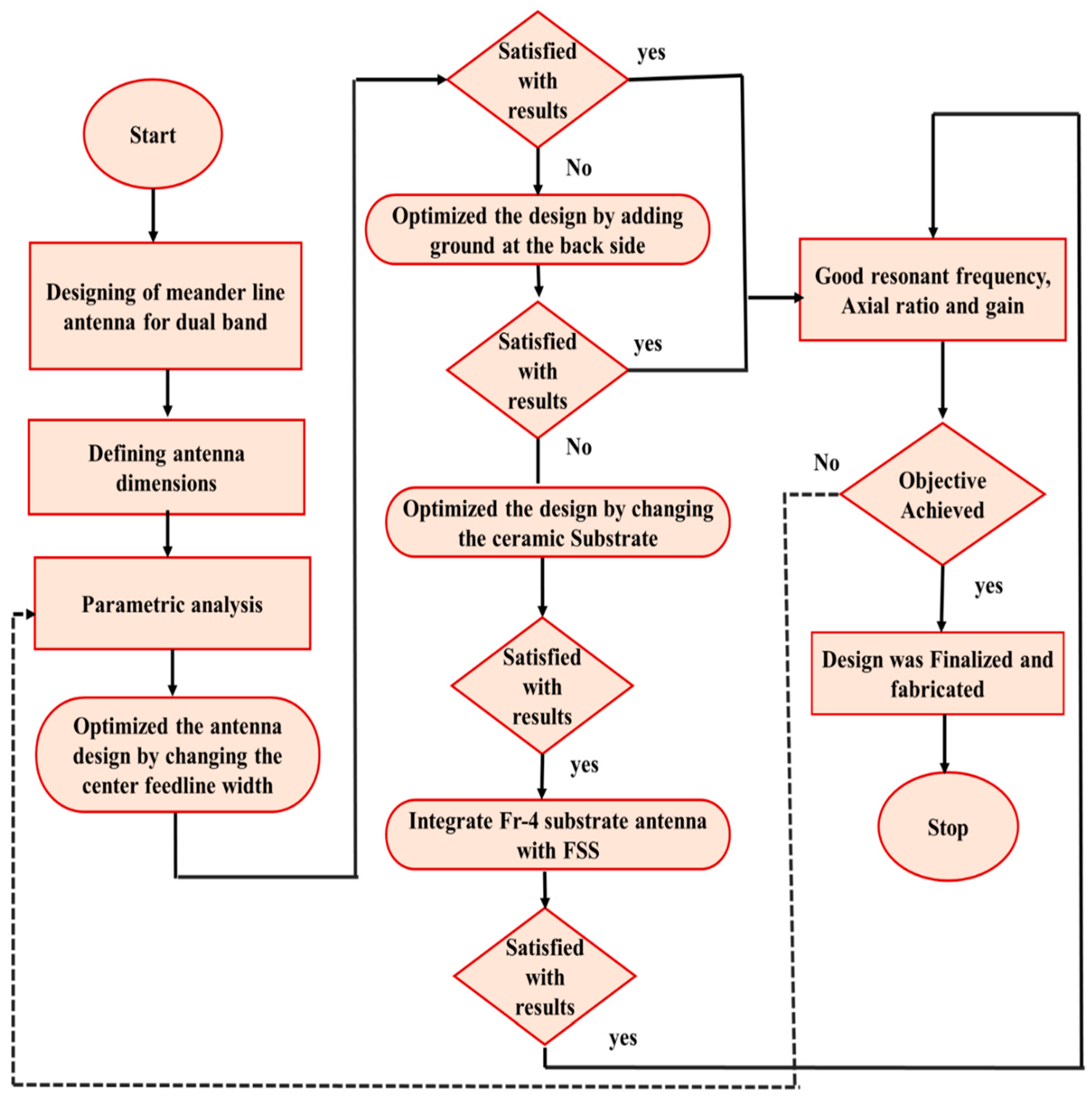
The vertical and horizontal components of the CPW-interleaved meander line antenna each have a different function. Generally, meander lines behave in a capacitive manner when they are oriented horizontally. This is because the meander line’s closely spaced segments form a structure that functions electrically, like a capacitor. Like a parallel plate capacitor, the electric field lines connecting the meander line’s neighboring segments store electrical energy. On the other hand, meander lines tend to behave inductively when they are oriented vertically. Each vertical section creates a magnetic field around itself as electricity passes through it. These segments are so close to one another that the structure exhibits inductor-like electrical behavior. Magnetic energy is stored in the magnetic field lines connecting the segments like a solenoid. The various design analyses of antenna steps are explained in the flow chart, as displayed in Figure 2.
Design 1:
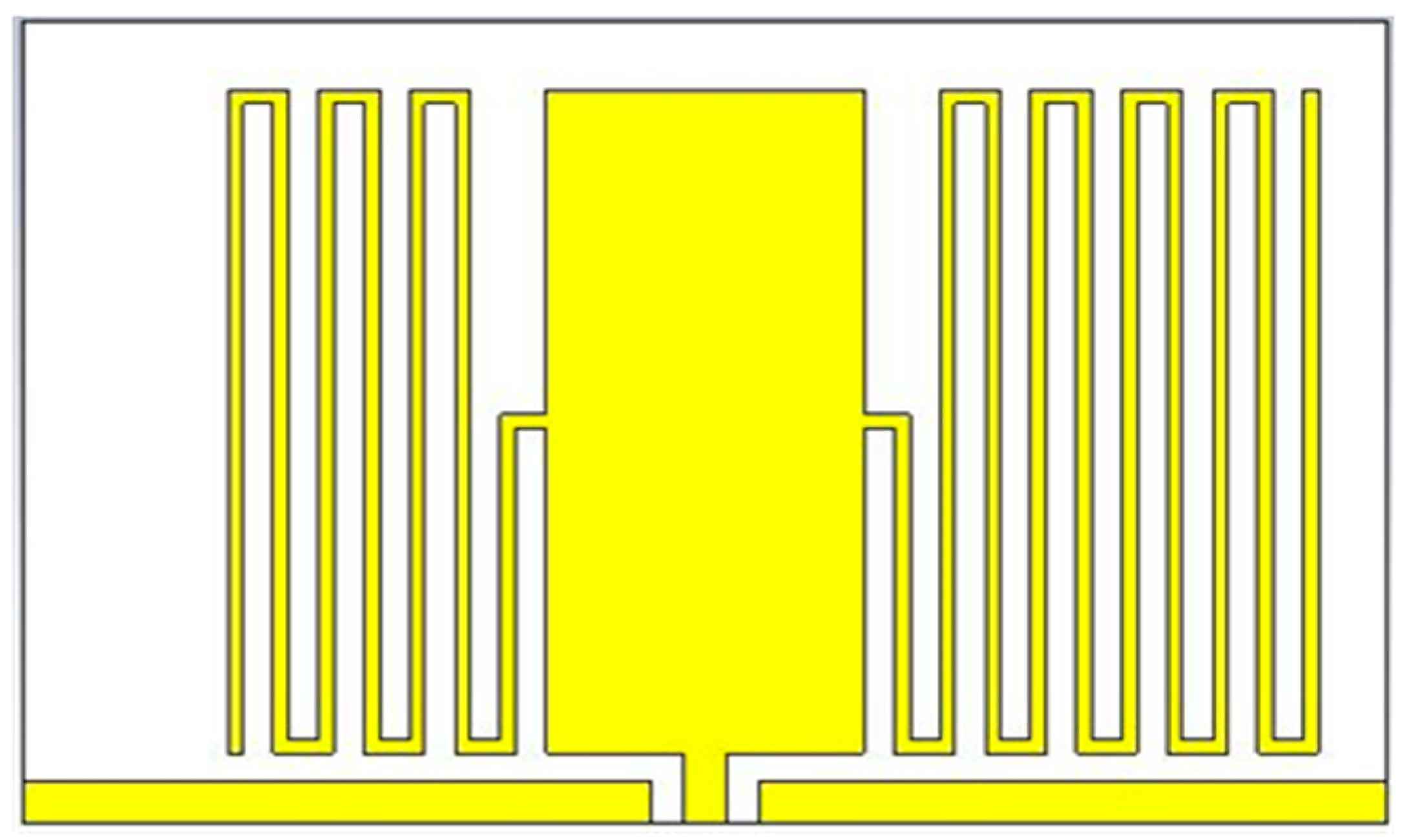
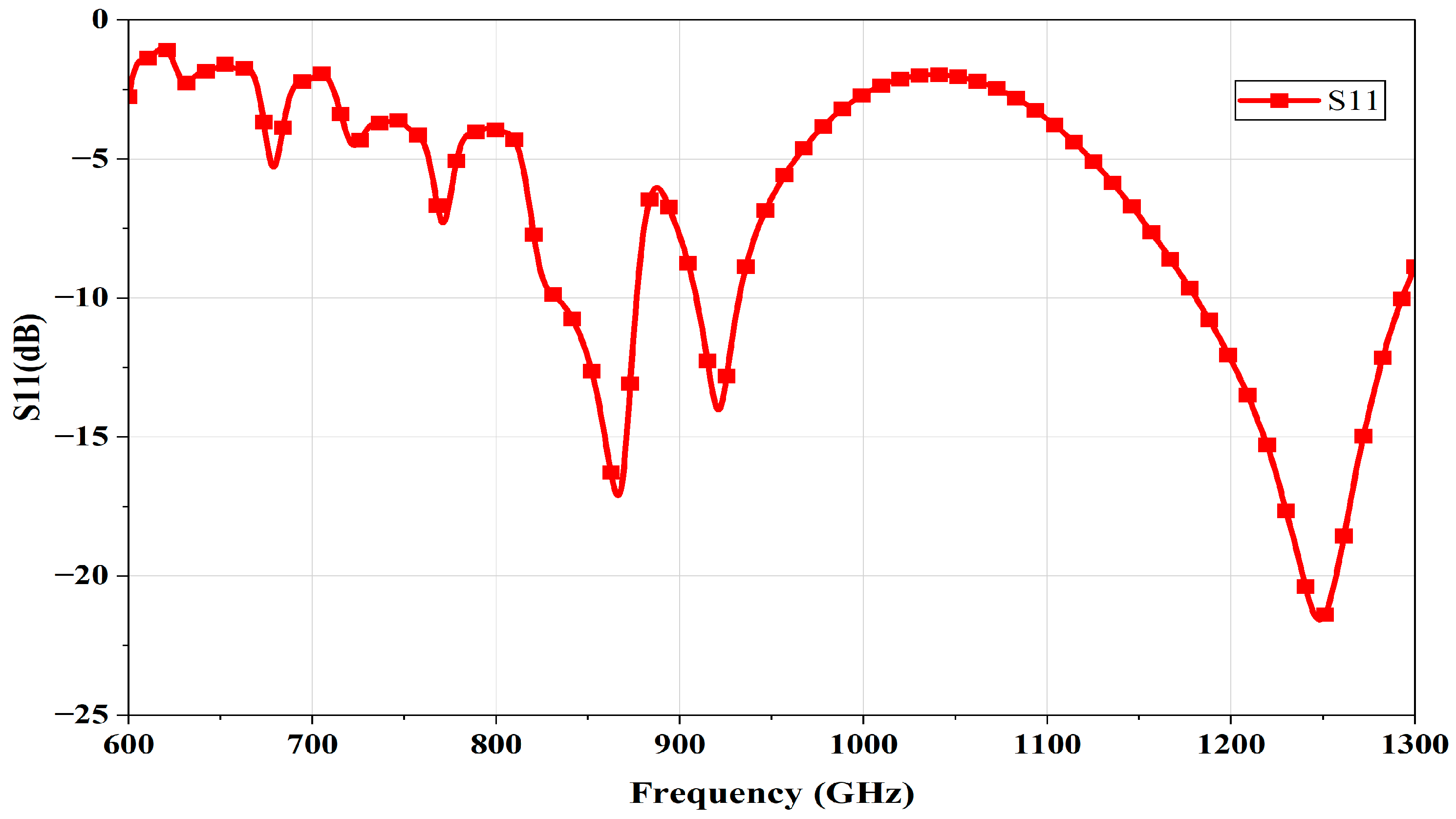
The FR-4 substrate (1.6 mm thickness, relative permittivity of 4.3) and copper annealed patch (0.035 mm thickness) comprise the antenna, as shown in Figure 3. The following are the antenna’s dimensions: The substrate measures 90 mm in length and 110 mm in width. The line spacing and width of the meander lines utilized are 4 mm and 1 mm, respectively, as displayed in Table 3. The antenna’s above-mentioned design achieves a dual band by placing an unequal number of meander lines on each patch. The frequencies at which resonance is reached are 868.1 MHz and 1115.2 MHz, as displayed in Figure 4. Thus, the LoRa band has been achieved. Now, we move on to design 2 to reach the GNSS frequency range.
Design 2:
The above antenna comprises an FR-4 substrate (1.6 mm thickness, 4.3 relative permittivity) and a copper annealed patch (0.035 mm thickness) using a transmission line, as shown in Figure 5. The following are the antenna’s dimensions: The substrate measures 90 mm in length and 90 mm in width. The line spacing and width of the meander lines utilized are 4 mm and 1 mm, respectively, as displayed in Table 4. As mentioned earlier, the antenna achieves a dual band by placing an equal number of meander lines on either side of the transmission line. The frequencies at which resonance is reached are 868.08 MHz and 1248.2 MHz, as illustrated in Figure 6. Thus, the LoRa and GNSS bands have been achieved. Now, we move on to design 3 to optimize the axial ratio.
Design 3:
In Figure 7, the antenna comprises a ceramic substrate (4 mm thickness, relative permittivity of 1) and a copper annealed patch (0.035 mm thickness), using a transmission line. The detailed dimensions are displayed in Table 5. The antenna mentioned above achieves a dual band by placing an equal number of meander lines on either side of the transmission line. The frequencies at which resonance is reached are 868.8 MHz and 1157.2 MHz, as displayed in Figure 8. Axial ratio (AR) has been optimized such that circular polarization (AR = 2.5) was achieved in the LoRa frequency range and elliptical polarization (AR = 4.6) was achieved in the GNSS Frequency range. Now, we move on to design 4 to improve the gain.
Design 4:
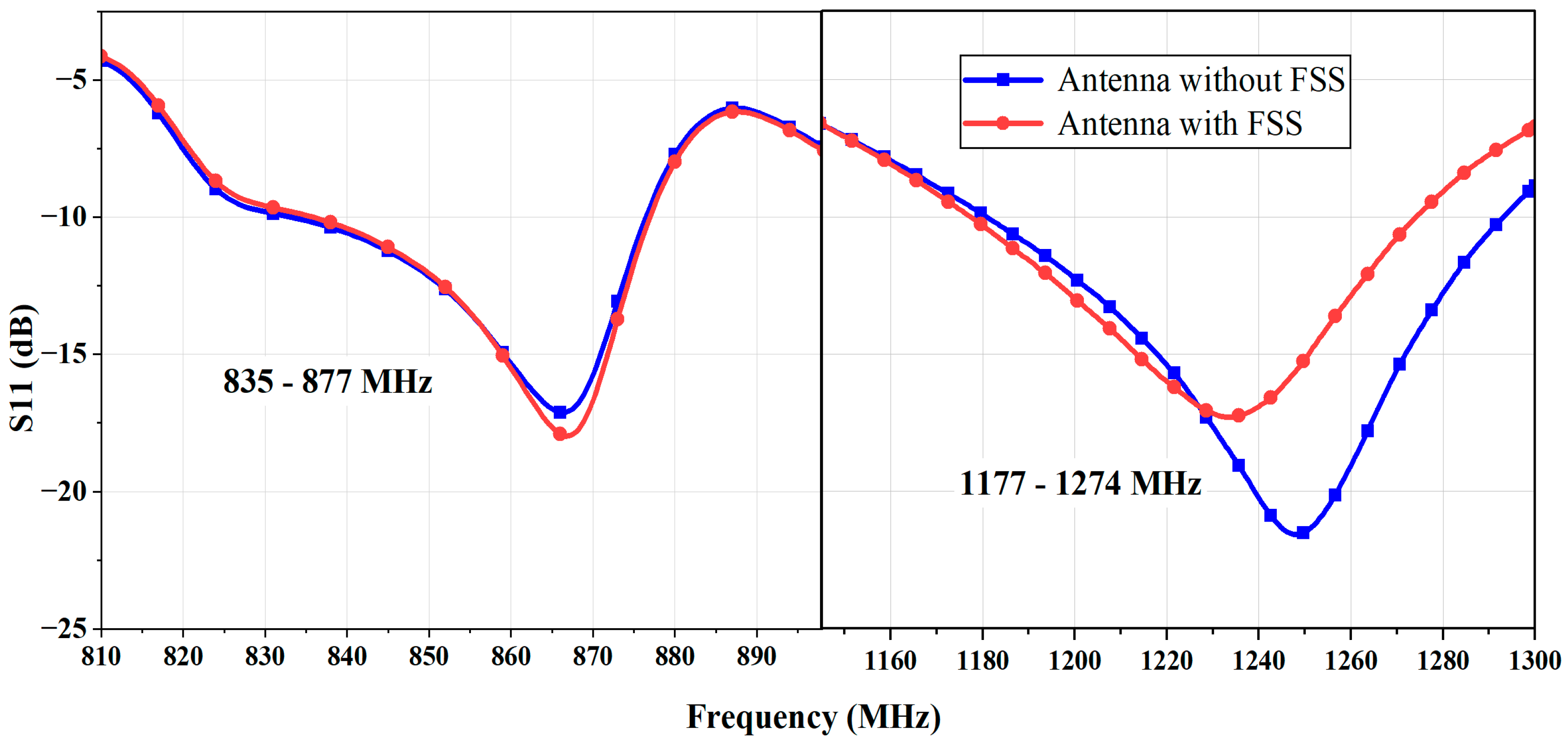
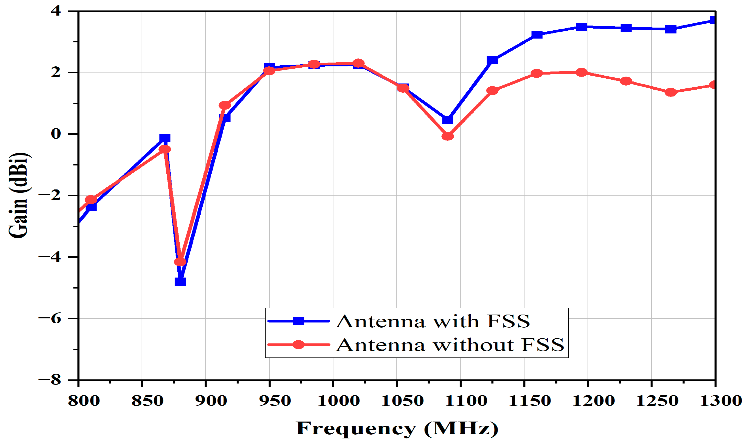
The design 2 antenna was integrated with a Frequency Selective Surface (FSS) measuring 90 mm × 90 mm, consisting of nine unit cells each measuring 30 mm × 30 mm, as shown in Figure 9. The FSS was positioned behind the antenna at a distance of 30 mm. The resonant frequencies are at 868.09 MHz and 1248.9 MHz. When the FSS was placed at the back of the antenna, the GNSS band shifted slightly compared to the version without FSS, due to the addition of reactive loading. This alters the current distribution of the antenna, reducing the reflection coefficient depth while maintaining an S11 of <−10 dB, as shown in Figure 10. The gain improved by 1.5 dB in the LoRa frequency range and 1.2 dB in the GNSS range.

4. Results and Discussion

The coplanar waveguide-interleaved meander line antenna design has been comprehensively evaluated through simulations covering impedance bandwidth, gain, axial ratio, VSWR, radiation patterns, and current distribution. A further proposed antenna was fabricated, and its performance was experimentally tested.

4.1. Simulation Results

4.1.1. Impedance Bandwidth

From Figure 10, it can be observed that the antenna with FSS provides an impedance bandwidth of around 40 MHz (S11 < –10 dB) at the LoRa band, while at the GNSS band it exhibits a wider bandwidth of 98 MHz (S11 < –10 dB).

4.1.2. Gain

Figure 11 illustrates the gain performance of the proposed double-band antenna for LoRa and GNSS applications. The antenna achieves a gain of –0.12 dBi at the LoRa band and 3.5 dBi at the GNSS band. The proposed LoRa antenna’s gain of −0.12 dBi is higher than that reported in related works [32]. These results confirm that the antenna maintains stable radiation characteristics across both operating frequencies, making it suitable for reliable dual-band communication.

4.1.3. Axial Ratio

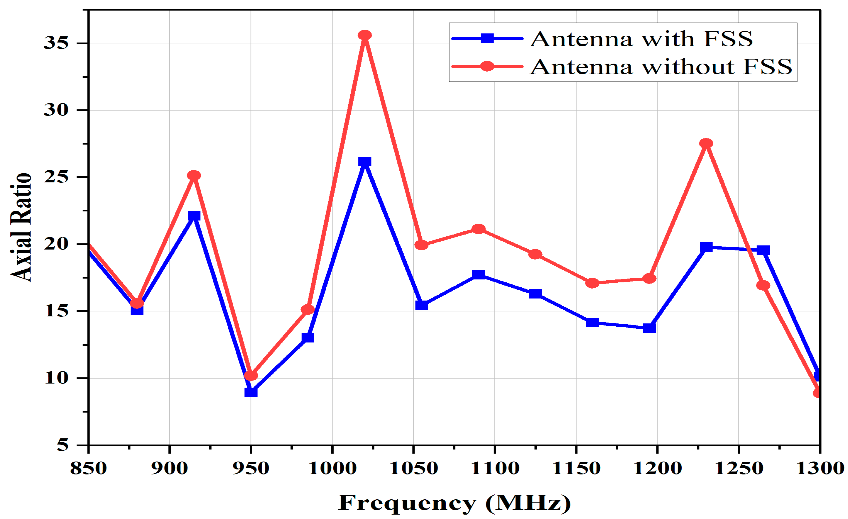
Figure 12 illustrates the dual-band antenna’s axial ratio (AR) performance for LoRa and GNSS applications. The AR characterizes the polarization of an antenna. A meander-line antenna achieves axial ratio values of around 8.4 at the LoRa band and 9.4 at the GNSS band, confirming linear polarization at both bands. The linear polarization antenna provides benefits over circular polarization in multipath environments [32]. This antenna was tested in an outdoor scenario to receive the GNSS signal.

4.1.4. VSWR

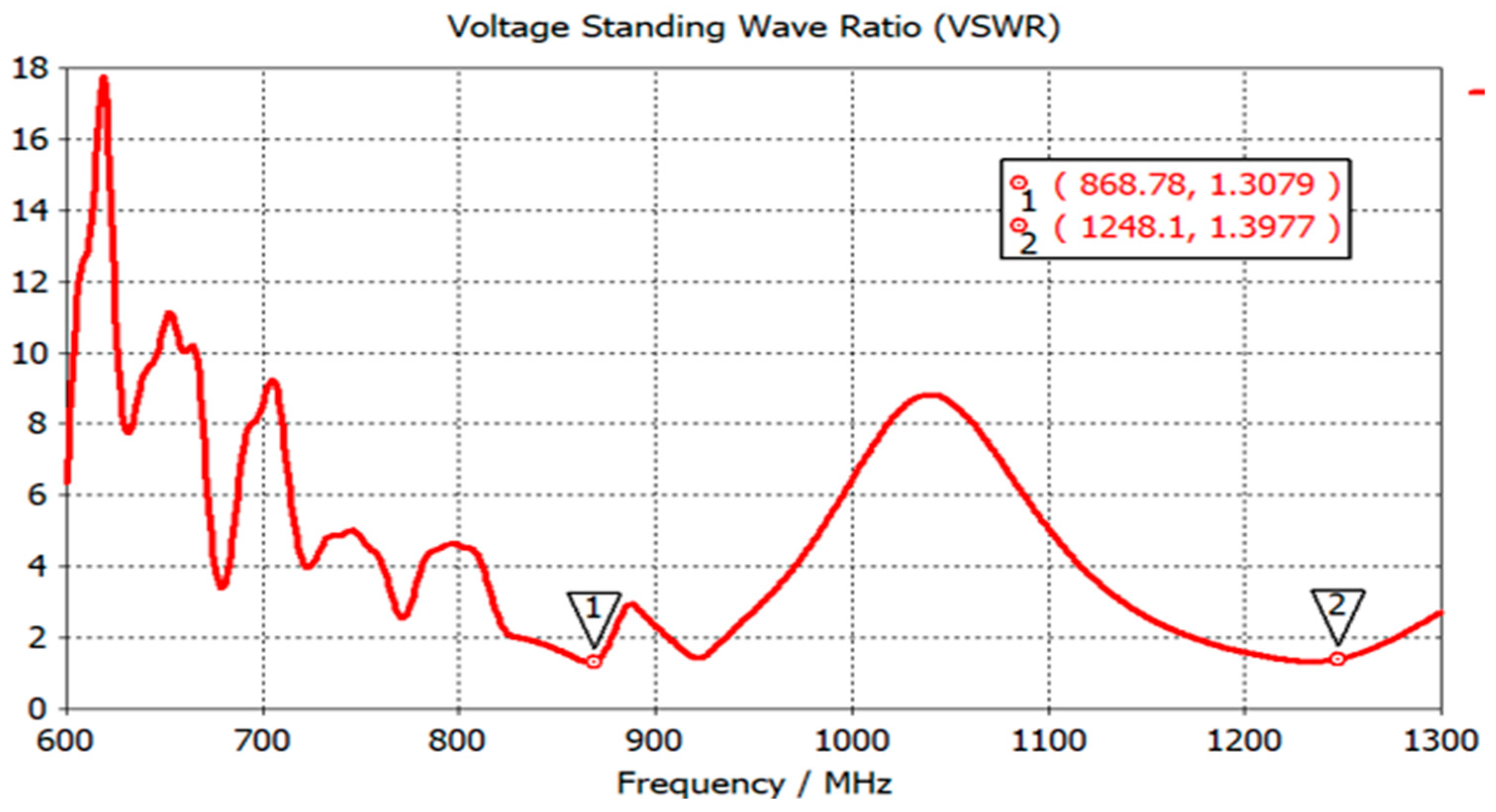
Figure 13 depicts the voltage standing wave ratio (VSWR) response of the CPW-interleaved meander line antenna at 868 MHz and 1248 MHz. The antenna achieves a VSWR of below 2 in both frequency bands, indicating good impedance matching and efficient power transfer. This performance confirms the antenna’s capability to operate effectively across the designated dual-band frequencies.
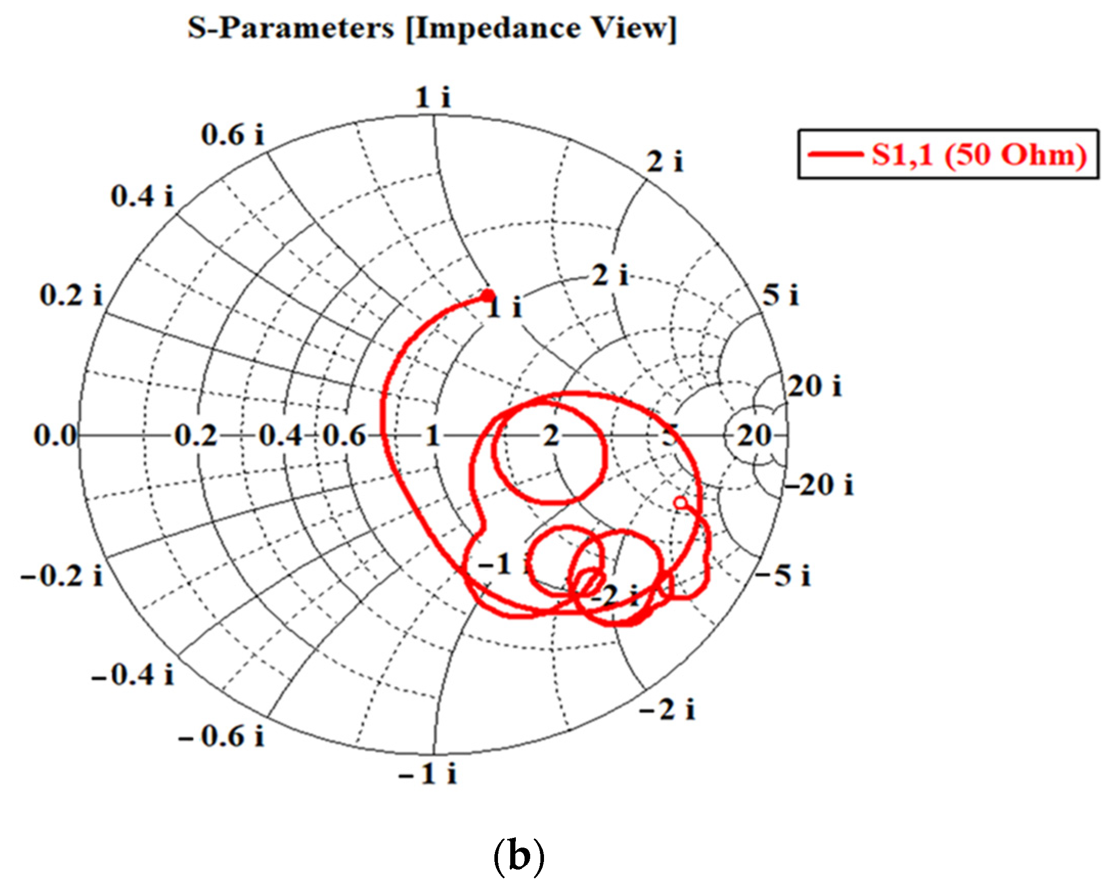
The antenna receives the electrical signal through the feed line, which connects the antenna to a transmission line. The proposed antenna is assigned a 50-ohm impedance at the feed line port to ensure proper electromagnetic radiation. The port signal for LoRa and GNSS frequencies is illustrated in Figure 14a. Figure 14b shows the Z Smith chart for 50-ohm impedance matching at both frequencies.

4.1.5. Radiation Pattern

Figure 15 presents the simulated directivity of the CPW-interleaved meander line antenna in the E- and H-planes. Figure 15a,b demonstrate that, at the LoRa band, the antenna exhibits a directional pattern in the H-plane and an omnidirectional radiation pattern in the E-plane. This combination ensures broad coverage while maintaining focused signal strength, making it well-suited for efficient LoRa network deployment. In contrast, Figure 15c,d illustrate that, at the GNSS band, the antenna exhibits directional patterns in both the E- and H-planes. The red curve shows the E-plane radiation pattern (φ = 0°), the green curve indicates the H-plane pattern (φ = 90°), and the blue lines mark the reference directions. This characteristic is particularly advantageous for vehicle localization, where focused signal concentration in specific directions enhances positioning accuracy.

4.1.6. Current Distribution

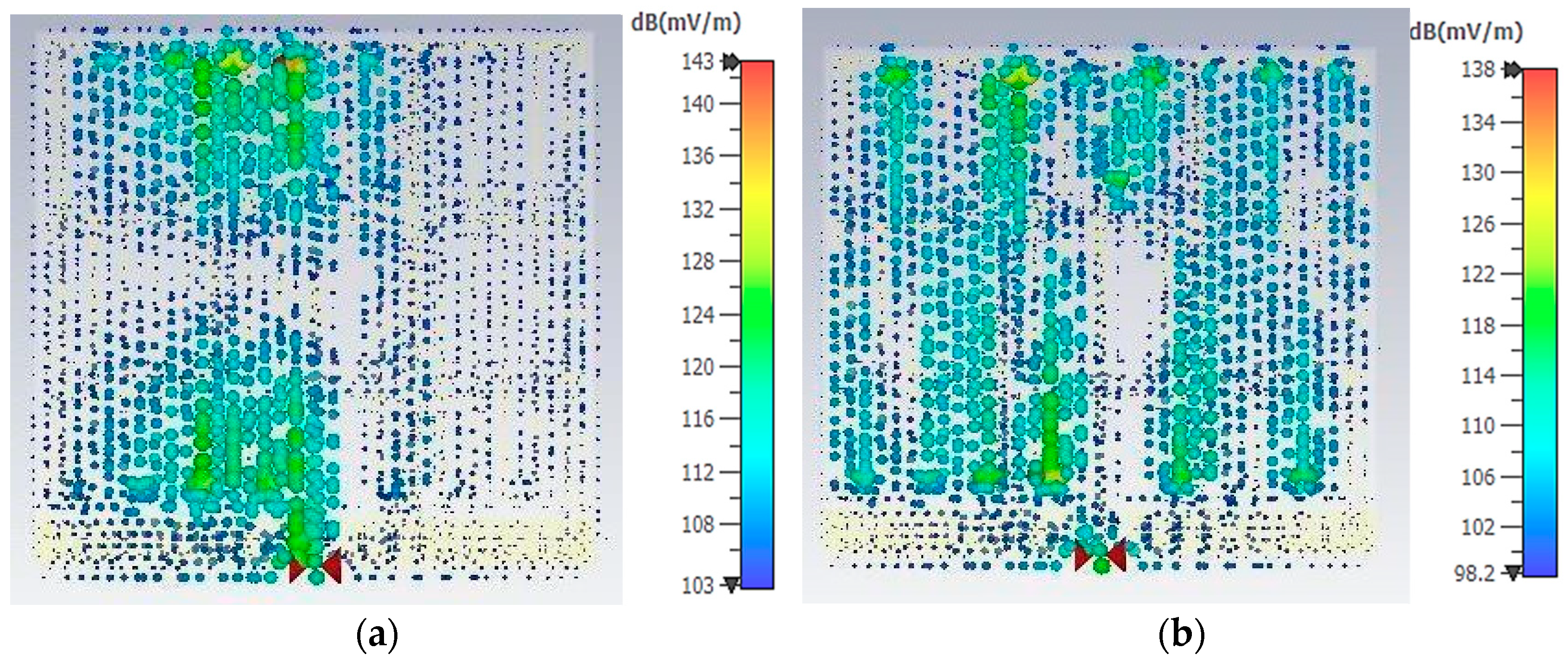
Current distribution characterizes the flow of surface currents on the antenna when excited by an input signal. It reveals the functional regions of the structure responsible for efficient radiation and reception. In CPW-interleaved meander line antennas, the current typically follows the serpentine conductive traces of the structure. Figure 16a depicts the current distribution at the LoRa band, where the dominant currents are concentrated along the meander lines adjacent to the transmission line on both sides. In contrast, Figure 16b shows the current distribution at the GNSS band, with the primary contribution arising from the meander lines positioned immediately to the left of the transmission line.

4.2. Prototype and Measurement Results

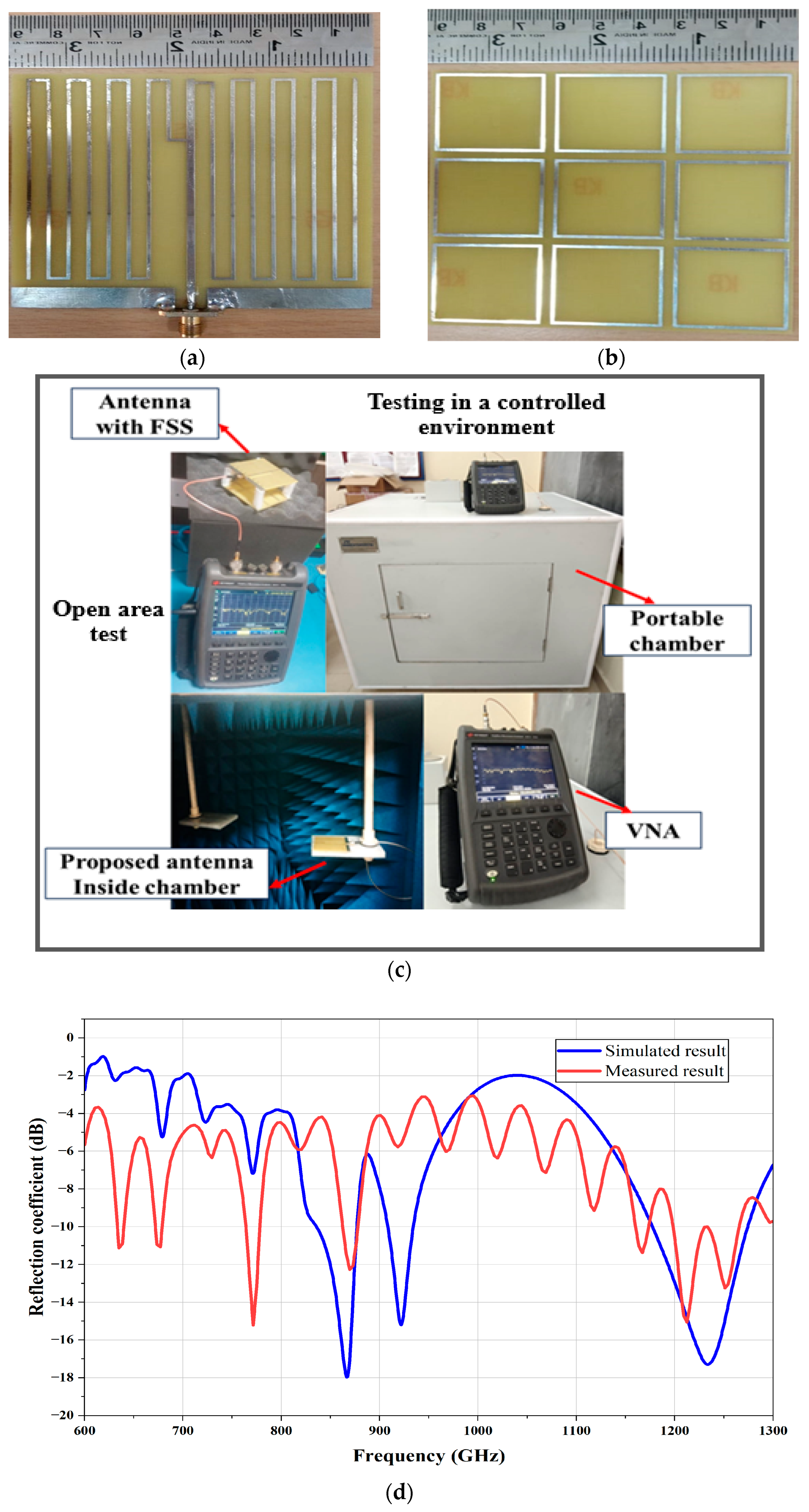
The fabricated CPW-interleaved meander line antenna and FSS for LoRa and GNSS bands are shown in Figure 17a,b. The fabricated FSS-based antenna’s S11 parameter was measured using VNA outside and inside the chamber in the frequency range of 600 to 1400 MHz, as shown in Figure 17c. The fabricated meander lines antenna with FSS achieved S11 < −10 dB at 868 MHz and 1248 MHz dual frequencies. It also matched the results of the simulator S11 parameter. The simulated and measured S-parameter comparison is depicted in Figure 17d.

5. Experimental Results

The USRP is a radio system designed for quick development and implementation. It was chosen because of its high performance, high degree of customization, flexibility in power consumption, and low cost compared to other market options. In this work, the USRP B210 has been demonstrated to be a good option. An RF front end with DACs and ADCs is included in the system. When connected to a computer, an SDR becomes a complete SDR system, allowing MATLAB/Simulink to handle the remaining signal processing.

5.1. Setup 1

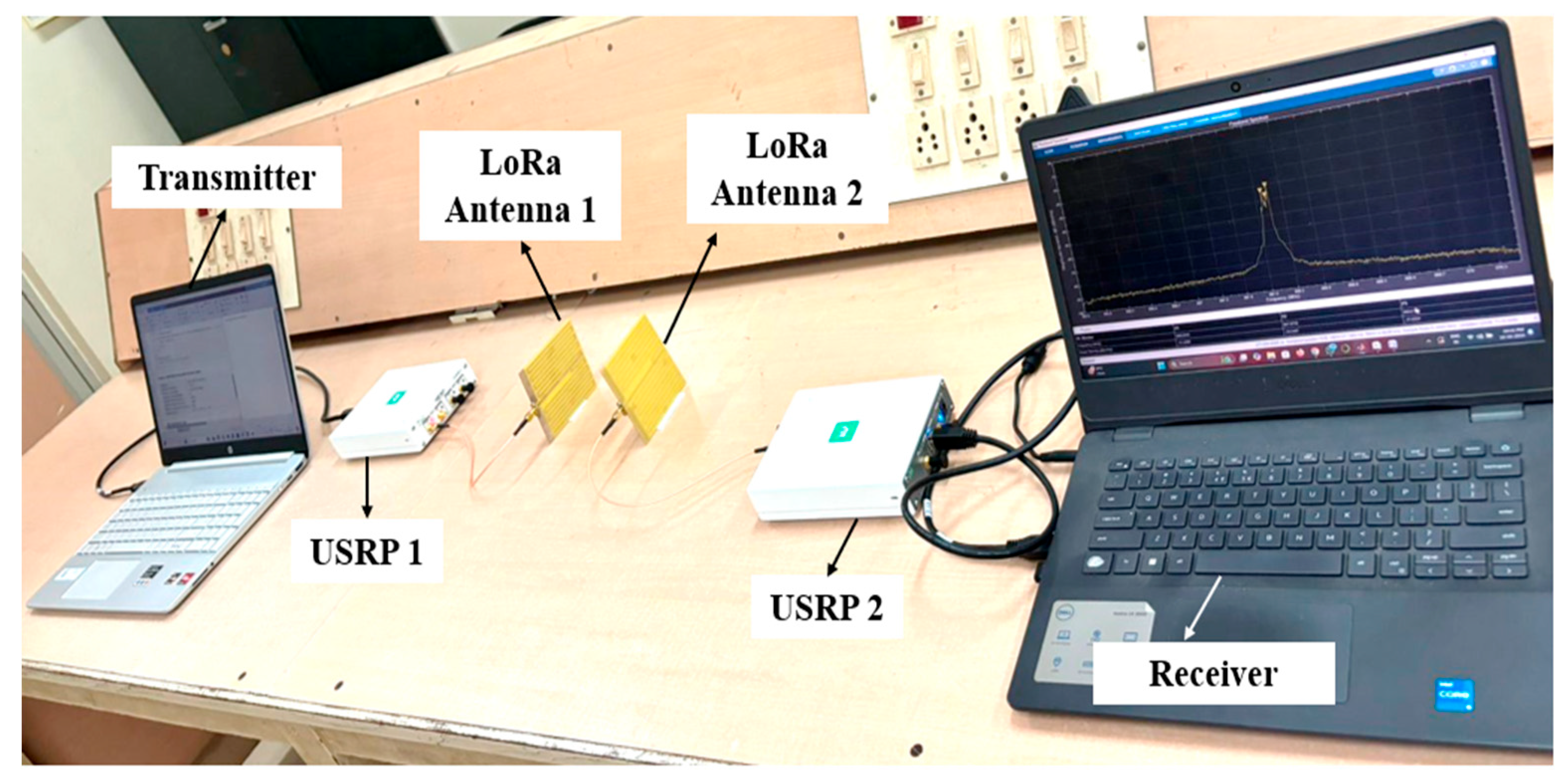
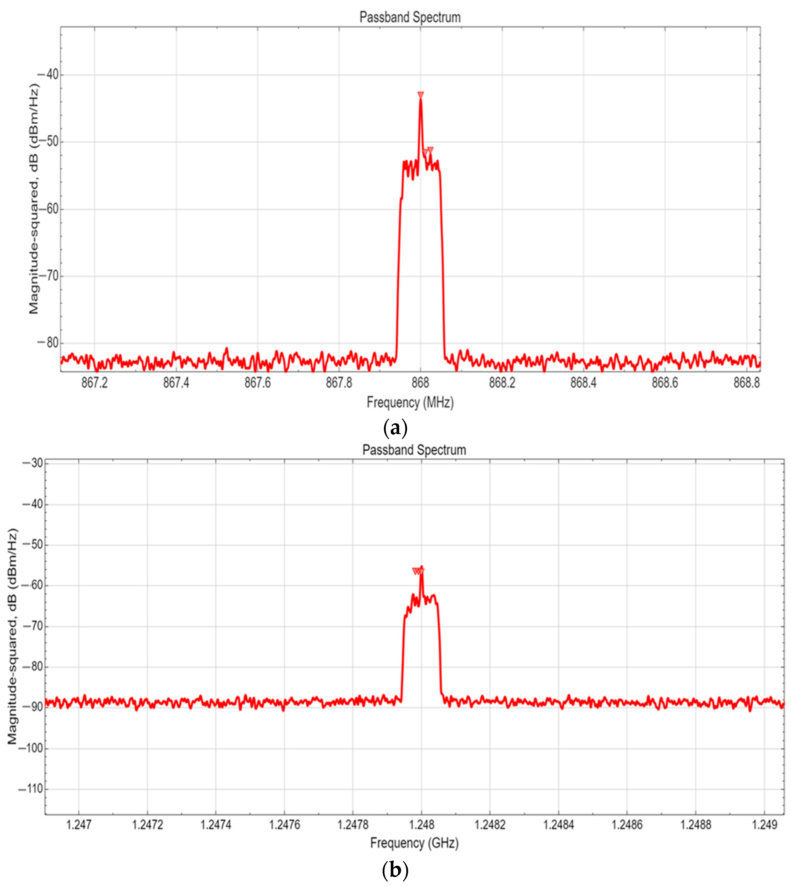
Real-time transmission and reception were developed for the LoRa signal using software-defined radio, as shown in Figure 18. The system connects to the USRP 1 and LoRa antenna on the transmitter side to transmit the signal using MATLAB 2024a/Simulink. Here, two LoRa antennae are utilized for signal transmission and reception. The antenna receives the transmitted signal using USRP 2 on the receiver side. In the transmitted block, the signal processing undergoes DC offset removal through a DC blocker to secure spectral analysis. The simulated signal is shown in the passband spectrum to display the power spectral density across frequencies. The real-time LoRa operating frequency spectrum at 868 MHz and 1248 MHz is depicted in Figure 19a and 19b, respectively.

5.2. Setup 2

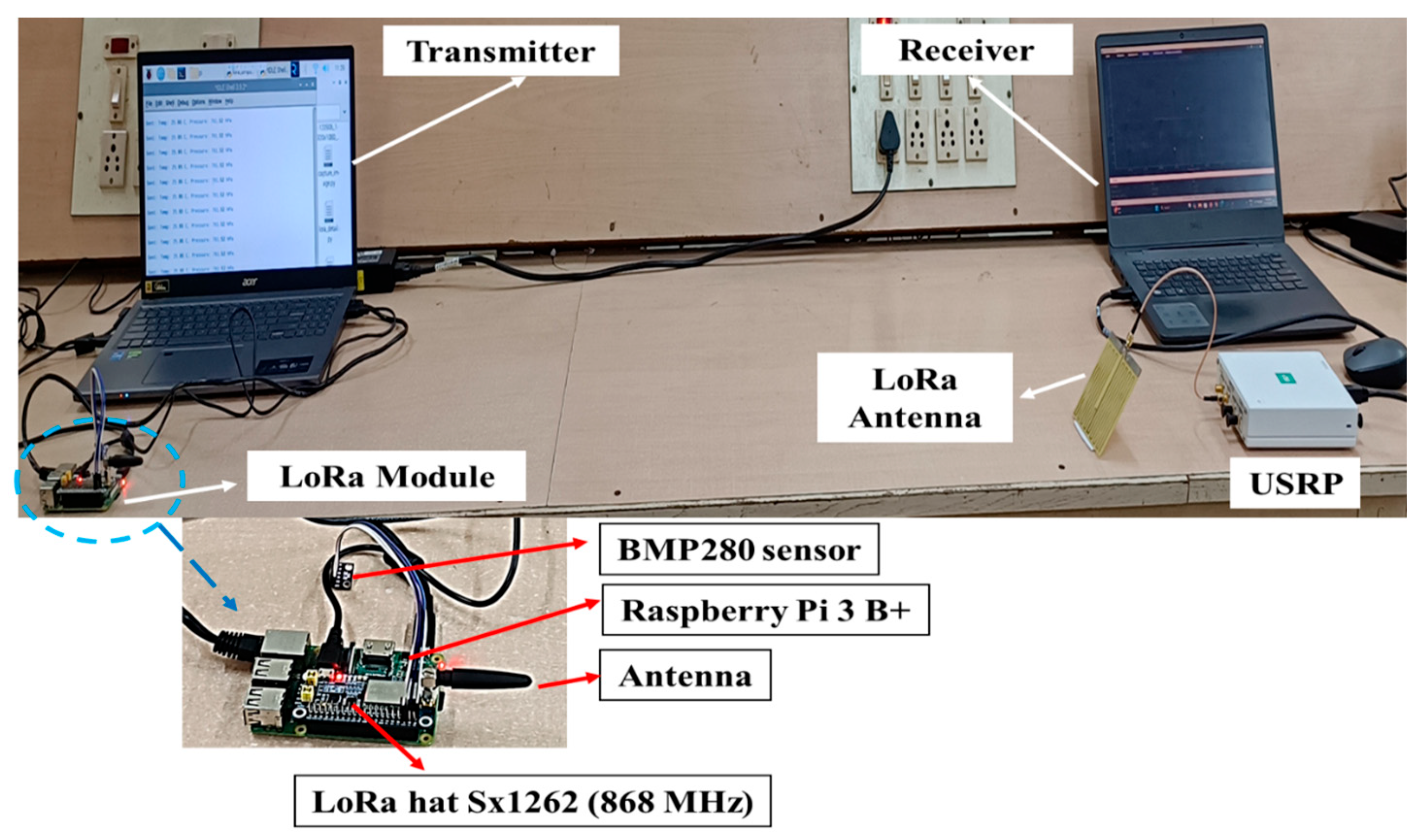
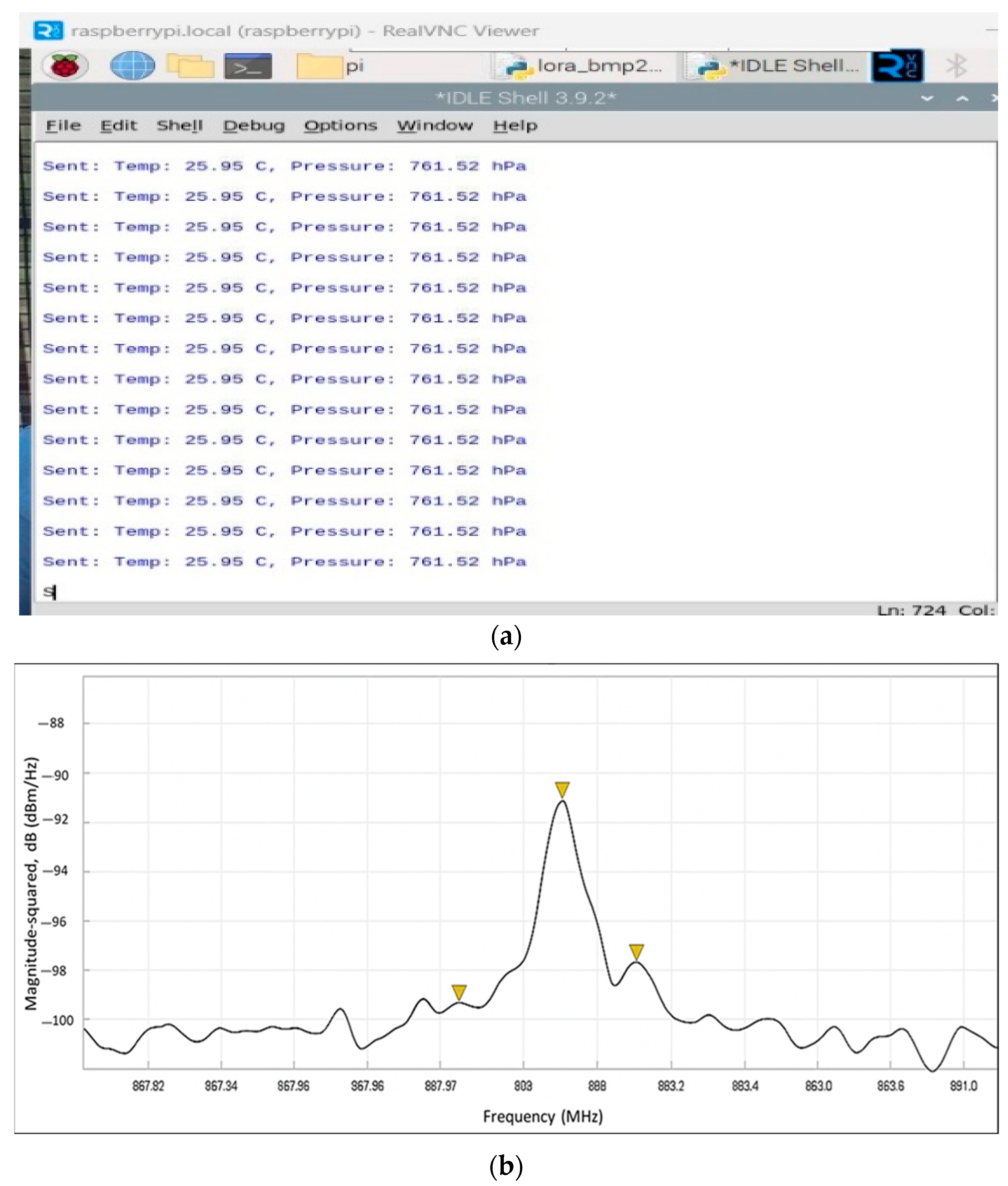
In this setup, an experiment of real-time transmission and reception of the LoRa signal is conducted at the operating frequency of the LoRa band. On the transmitter side, the system is connected to the Raspberry Pi 3 B+ module with LoRa HAT Sx1262 and BMP280 sensors for pressure and temperature analysis, as shown in Figure 20. The Raspberry Pi processes the data from the temperature and pressure sensors, which can be observed in real-time through the Python 3.8 version program running on the Raspberry Pi, as shown in Figure 21a. On the receiver side, the LoRa antenna captures the transmitted signal, which is processed on a USRP device. The frequency spectrum at 868 MHz is shown in Figure 21b, representing a real-time signal received from the transmitter. The yellow triangle in the curve represents the peak value of the spectrum at LoRa band.

5.3. Setup 3

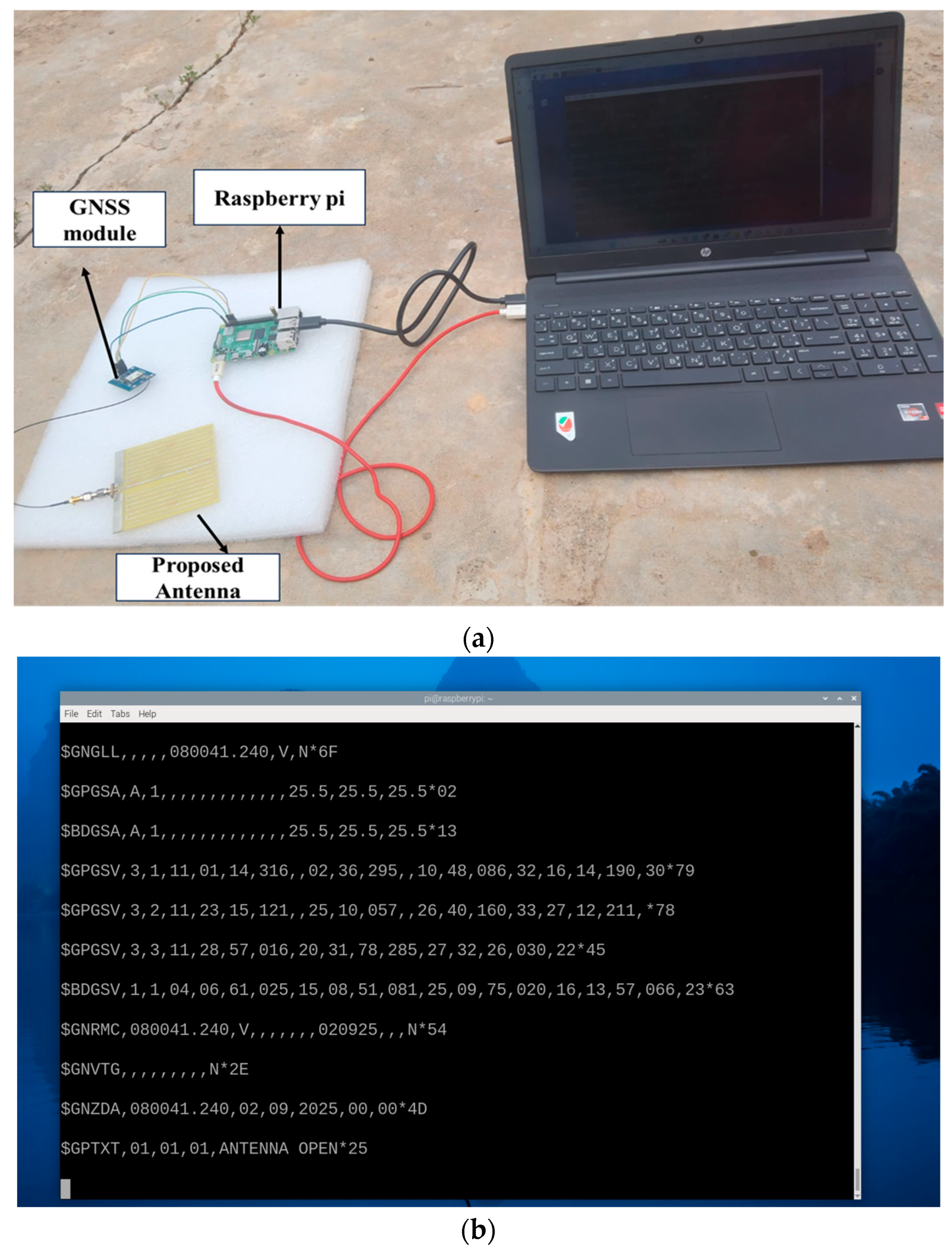
The proposed antenna is tested outdoors to receive GNSS signals. Real-time reception of the GNSS signal is performed using a Neo 6 m GNSS module and a Raspberry Pi, and the setup is powered through a laptop, as shown in Figure 22a. The antenna receives the satellite information and location through the antenna and GNSS module, as illustrated in Figure 22b. This shows the performance of antenna reception.

6. Conclusions

A dual-band CPW-interleaved meander line antenna integrated with a Frequency Selective Surface (FSS) for LoRa and its applications demonstrates notable performance across several parameters. The antenna obtains a bandwidth of 40 MHz for the LoRa (868 MHz) band and 110 MHz for the GNSS (1248 MHz) band. A VSWR consistently below 2 shows a better impedance match between the radiating element and the feedline. It provides reliable signal amplification for both frequency ranges, with a gain of −0.12 dBi at 868 MHz and 3.5 dBi at 1248 MHz. Additionally, the axial ratios of 8.4 at 868 MHz and 9.4 at 1248 MHz ensure polarization purity, which is vital for accurate communication and navigation. The radiation pattern shows omnidirectional characteristics at 868 MHz, which is suitable for LoRa applications, and directional properties at 1248 MHz, which is advantageous for GNSS applications requiring focused signal coverage. The optimized current distribution improves radiation properties, ensuring efficient electromagnetic wave emission and reception. The antenna was analyzed through spectrum plots, and testing was conducted using a LoRa HAT module and a GNSS module to evaluate real-time reception. The proposed antenna provides a compact, efficient, and cost-effective solution for advancing vehicular communication and navigation technologies across various industries and applications.

Author Contributions

Conceptualization, S.G.; Data curation, M.C.; Methodology, R.A.; Software, K.D.S.M. and K.S.N.R.; Validation, M.C. and R.A.; Visualization, K.S.N.R.; Writing—original draft, S.G.; Writing—review and editing, K.D.S.M. All authors have read and agreed to the published version of the manuscript.

Funding

We would like to thank and acknowledge the IIT Tirupati Navavishkar I-Hub Foundation (IITTNiF), the National Mission on Interdisciplinary Cyber-Physical Systems (NM-ICPS), and the Department of Science and Technology (DST), India, for their financial support (SASTRA-IITTNiF/5GNP/2024-25) and the SASTRA Deemed University, India, for providing the necessary resources. We sincerely thank Elamparithi R and Saranya J for their involvement and valuable support during the real-time testing of this work.

Data Availability Statement

The authors declare that any data related to this research will be made available on request to the corresponding author, Dr Manikandan Chinnusami (manikandan@ece.sastra.ac.in) and Dr Rajesh Anbazhagan (rajesha@ece.sastra.edu).

Conflicts of Interest

The authors declare no conflicts of interest.

Abbreviations

The following abbreviations are used in this manuscript:
LORALong Range
GNSSGlobal Navigation Satellite System
FSSFrequency Selective Surface
CDBMPACompact Dual Band Microstrip Patch Antenna
TEtransverse electric
ISMIndustrial, Scientific, and Medical
C-V2XCellular-vehicle to everything
V2IVehicle to Infrastructure
V2VVehicle to vehicle
PIFAPlanar Inverted-F Antenna
VSWRVoltage Standing Wave Ratio
UAVUnmanned Aerial Vehicle
WiMAXWorldwide Interoperability for Microwave Access
FR-4flame resistant
WANWide Area Network
CSRRComplementary Split Ring Resonator
CSTComputer Simulation Technology
ARAxial Ratio
VNAVector Network Analyzer
DACsDigital to Analog Converter
ADCsAnalog to Digital Converter
USRPUniversal Software Radio Peripheral
MATLABMatrix Laboratory
SDRSoftware-Defined Radio
RFRadio Frequency
DCDirect Current

References

  1. Sneha, B.M.; Gupta, P.; Singh, A.R. Real-Time Implementation of a Novel Design Approach for Sub-GHz Long-Range Antenna for Smart Internet of Things Communication. Int. J. Antennas Propag. 2023, 14, 8602885. [Google Scholar] [CrossRef]
  2. Mekap, D.; Soni, P.; Yadav, D.W. A Microstrip Patch Antenna with a Star Shaped Slot and a Phase Gradient Metasurface. In Proceedings of the 2022 International Conference for Advancement in Technology (ICONAT), Goa, India, 21–22 January 2022; pp. 1–4. [Google Scholar] [CrossRef]
  3. Chatterjee, A.; Sharma, D.S.; Samantaray, D.; Sarkar, C.; Saha, C.; Bhattacharyya, S. Design of a Printed Triangular Patch Antenna Loaded with Novel Trident-Shaped Metasurface and Defected Ground Plane. In Proceedings of the 2020 URSI Regional Conference on Radio Science (URSI-RCRS), Varanasi, India, 12–14 February 2020; pp. 1–4. [Google Scholar] [CrossRef]
  4. Zhang, Q.; Gao, Y. Embedded Antenna Design on LoRaRadio for IoT Applications. In Proceedings of the 12th European Conference on Antennas and Propagation (EuCAP2018), London, UK, 9–13 April 2018; p. 3. [Google Scholar]
  5. Soni, D.; Wadhwa, P.; Yadav, D.; Tiwari, M. Multiband Sand Timer Shaped Microstrip Patch Antenna with a Metasurface for Gain Enhancement. In Proceedings of the 2021 IEEE Indian Conference on Antennas and Propagation (InCAP), Jaipur, Rajasthan, India, 13–16 December 2021; pp. 610–613. [Google Scholar] [CrossRef]
  6. Mishra, P.; Bhakta, S.; Sengupta, D.J. Microstrip circularly polarized dual band Patch antenna design for NaVIC application. In Proceedings of the 2022 13th International Conference on Computing Communication and Networking Technologies (ICCCNT), Kharagpur, India, 3–5 October 2022; pp. 1–4. [Google Scholar] [CrossRef]
  7. Maharana, S.; Vamshi Krishna, N.; Ganesh, T.S.; Raghavendra, M.R. Design and realization of a Dual Microstrip patch antenna for NavIC Applications. In Proceedings of the 2022 URSI Regional Conference on Radio Science (USRI-RCRS), Indore, India, 1–4 December 2022; pp. 1–4. [Google Scholar] [CrossRef]
  8. Anshu, G.; Navneet, A. The IRNSS/NavIC designing characteristics and development in antenna application: An overview. Comput. Telecommun. Eng. 2023, 1, 2266. [Google Scholar] [CrossRef]
  9. Modi, A.; Sharma, V.; Rawat, A. Compact Design of Multiband Antenna for IRNSS, Satellite, 4G and 5G Applications. In Proceedings of the 2021 5th International Conference on Computing Methodologies and Communication (ICCMC), Erode, India, 8–10 April 2021; pp. 6–9. [Google Scholar] [CrossRef]
  10. Das, P.; Biswas, S.; Ridhwaan, S.S.; Ray, R.; Ghosh, D.; Sarkar, D. Design and Analysis of Frequency Selective Surface Integrated Circular Disc Antenna. In Proceedings of the 2018 2nd International Conference on Electronics, Materials Engineering & Nano-Technology (IEMENTech), Kolkata, India, 4–5 May 2018; pp. 1–5. [Google Scholar] [CrossRef]
  11. Zhan, S.; Weber, R.J.; Song, J. Effects of Frequency Selective Surface (FSS) on Enhancing the Radiation Efficiency of Metal-Surface Mounted Dipole Antenna. In Proceedings of the 2007 IEEE/MTT-S International Microwave Symposium, Honolulu, HI, USA, 3–8 June 2007; pp. 1659–1662. [Google Scholar] [CrossRef]
  12. Gangwar, D.; Nayak, A.K.; Patnaik, A. Design and Testing of a Microstrip Patch Antenna for Vehicle-to-Vehicle Communication. In Proceedings of the 2022 IEEE Microwaves, Antennas, and Propagation Conference (MAPCON), Bangalore, India, 12–15 December 2022; pp. 1218–1221. [Google Scholar] [CrossRef]
  13. Yahya, M.S.; Soeung, S.; Chinda, F.E.; Sovuthy, C.; Nor, N.B.M.; Rahim, S.K.A.; Musa, U. A Compact Dual Band Microstrip Patch Antenna for LoRaIoT Applications. In Proceedings of the 2022 IEEE International RF and Microwave Conference (RFM), Kuala Lumpur, Malaysia, 19–21 December 2022; pp. 1–4. [Google Scholar] [CrossRef]
  14. Raju, K.A.; Keerthi, C.S.; Srikalnyi, K.; Jyothika, U.; Mehaboob, A. Design of Flexible and Dual Band Antenna for Vehicular Communication. Int. Trans. Electr. Eng. Comput. Sci. 2023, 2, 163–171. [Google Scholar] [CrossRef]
  15. Nej, S.; Ghosh, A. Design of Meander Line Triple Band Antenna for Wireless Applications. In Proceedings of the 2020 Fourth International Conference on Computing Methodologies and Communication (ICCMC), Erode, India, 11–13 March 2020; pp. 690–693. [Google Scholar] [CrossRef]
  16. Islam, M.S.; Islam, M.T.; Ullah, M.A.; KokBeng, G.; Amin, N.; Misran, N. A Modified Meander Line Microstrip Patch Antenna with Enhanced Bandwidth for 2.4 GHz ISM-Band Internet of Things (IoT) Applications. IEEE Access 2019, 7, 127850–127861. [Google Scholar] [CrossRef]
  17. Roges, R.; Malik, P.K.; Sharma, S. A Compact Wideband Antenna with DGS for IoT Applications using LoRa Technology. In Proceedings of the 2022 10th International Conference on Emerging Trends in Engineering and Technology—Signal and Information Processing (ICETET-SIP-22), Nagpur, India, 29–30 April 2022; pp. 1–4. [Google Scholar] [CrossRef]
  18. Torres, A.P.A.; Silva, C.B.D.; Filho, H.T. An Experimental Study on the Use of LoRa Technology in Vehicle Communication. IEEE Access 2021, 9, 26633–26640. [Google Scholar] [CrossRef]
  19. Rahardi, R.; Rizqi, M.; Lukito, W.D.; Hilmi, M.; Virginio, R.; Munir, A. Compact Dipole Antenna Based on Meander Line Structure for Unmanned Aerial Vehicle Application. In Proceedings of the 2020 IEEE International Conference on Communication, Networks and Satellite (Comnetsat), Batam, Indonesia, 17–18 December 2020; pp. 174–177. [Google Scholar] [CrossRef]
  20. Mushtaq, A.; Gupta, S.H.; Rajawat, A. Design and performance analysis of LoRa LPWAN antenna for IoT applications. In Proceedings of the IEEE 2020 7th International Conference on Signal Processing and Integrated Networks (SPIN), Noida, India, 27–28 February 2020; pp. 1153–1156. [Google Scholar]
  21. Ibrahim, N.F.; Dzabletey, P.A.; Kim, H.; Chung, J.-Y. An all-textile dual-band antenna for BLE and LoRa wireless communications. Electronics 2021, 10, 2967. [Google Scholar] [CrossRef]
  22. Rui, H.; Xia, W.; Xing, L.; Zhu, F. A Dual-Band Footwear Textile Antenna for LoRa Off-Body Communication. In Proceedings of the 2022 IEEE Conference on Antenna Measurements and Applications (CAMA), Guangzhou, China, 14–17 December 2022; pp. 1–4. [Google Scholar]
  23. Amer, A.; Saraereh, O.A.; Ashraf, A.; Samer, A. Design of LoRa antenna for wearable medical applications. IEEE Access 2023, 11, 23886–23895. [Google Scholar] [CrossRef]
  24. Positano, F.; Lizzi, L.; Staraj, R. Design and on-field test of ESPAR antenna for UAV-based long-range IoT applications. Front. Antennas Propag. 2024, 2, 1429710. [Google Scholar] [CrossRef]
  25. Nguyen, M.T.; Ferrero, F.; Trinh, L.-H. Compact UHF circularly polarized multiband quadrifilar antenna for CubeSat. Sensors 2023, 23, 5361. [Google Scholar] [CrossRef] [PubMed]
  26. Ferrero, F.; Toure, M.B. Dual-band LoRa antenna: Design and experiments. In Proceedings of the 2019 IEEE Conference on Antenna Measurements & Applications (CAMA), Bali, Indonesia, 23–25 October 2019; pp. 243–246. [Google Scholar]
  27. Mangalla, M.; Edwar, E.; Hasbi, W.; Putra, N.A.H. Design of CubeSat microstrip antenna with metamaterial structure for LoRa communication. In Proceedings of the 2021 IEEE International Conference on Aerospace Electronics and Remote Sensing Technology, ICARES, Online, 3–4 November 2021; pp. 1–5. [Google Scholar]
  28. Wanpare, W.; Paisal, A.; Chalermwisutkul, S. A compact 923 MHz monopole antenna for LoRaWAN IoT applications. In Proceedings of the 2020 IEEE International Conference on Power, Energy and Innovations (ICPEI), Chiang Mai, Thailand, 14–16 October 2020; pp. 53–56. [Google Scholar]
  29. Drissi, M.; Benjelloun, N.; Descamps, P.; Gharsallah, A. Designing the MIMO SDR-based Antenna Array for 5G Telecommunication. Challenge 2022, 3, 4. [Google Scholar] [CrossRef]
  30. Krishna, M.V.; Raju, G. Triangle shaped antenna design for IoT-based Lorawan applications. SAMRIDDHI: J. Phys. Sci. Eng. Technol. 2021, 13, 8–11. [Google Scholar] [CrossRef]
  31. Bouyedda, A.; Barelaud, B.; Gineste, L. Design and realization of an UHF frequency reconfigurable antenna for hybrid connectivity LPWAN and LEO satellite networks. Sensors 2021, 21, 5466. [Google Scholar] [CrossRef] [PubMed]
  32. Gui, J.; Leiva, J.L.; Andújar, A.; Groot, J.; Pijoan, J.L.; Anguera, J. Linearly Polarized Antenna Boosters versus Circularly Polarized Microstrip Patch Antennas for GPS Reception in IoT Devices. Energies 2022, 15, 9623. [Google Scholar] [CrossRef]
Figure 1. (a) Evolution of the CPW-interleaved meander line antenna. (b) Geometry of the CPW-interleaved meander line antenna.
Telecom 06 00087 g001
Figure 2. Flow chart for antenna design.
Telecom 06 00087 g002
Figure 3. Dipole antenna with unequal meander lines on either side.
Telecom 06 00087 g003
Figure 4. Reflection coefficient of design 1.
Telecom 06 00087 g004
Figure 5. Meandered dipole antenna using a transmission line with an FR-4 substrate.
Telecom 06 00087 g005
Figure 6. Reflection coefficient response of design 2.
Telecom 06 00087 g006
Figure 7. Meandered dipole antenna using a transmission line with a ceramic substrate.
Telecom 06 00087 g007
Figure 8. Simulated results of the S-parameter.
Telecom 06 00087 g008
Figure 9. (a) Proposed Frequency Selective Surface (FSS) structure. (b) Meandered dipole antenna using transmission line with FR-4 substrate integrated with FSS.
Telecom 06 00087 g009
Figure 10. Reflection coefficient of antenna with and without FSS.
Telecom 06 00087 g010
Figure 11. Gain of the CPW-interleaved meander line antenna.
Telecom 06 00087 g011
Figure 12. Axial ratio of the proposed dual-band antenna.
Telecom 06 00087 g012
Figure 13. VSWR characteristics of the CPW-interleaved meander line antenna.
Telecom 06 00087 g013
Figure 14. (a) Port signal for LoRa and GNSS antenna. (b) Smith chart.
Telecom 06 00087 g014aTelecom 06 00087 g014b
Figure 15. Radiation pattern. (a) E-plane at LoRa band; (b) H-plane at LoRa band; (c) E-plane at GNSS band; and (d) H-plane at GNSS band.
Telecom 06 00087 g015aTelecom 06 00087 g015b
Figure 16. Current distribution: (a) LoRa band and (b) GNSS band.
Telecom 06 00087 g016
Figure 17. (a) Fabricated dual-band meander lines antenna (b) Fabricated FSS. (c) Measurement setup (d) Comparisons of Simulated vs. measured results.
Telecom 06 00087 g017
Figure 18. Implementation of the experimental setup.
Telecom 06 00087 g018
Figure 19. Frequency spectrum (a) at 868 MHz and (b) 1248 MHz.
Telecom 06 00087 g019
Figure 20. Experimental setup of transmission and reception.
Telecom 06 00087 g020
Figure 21. (a) Analysis of pressure and temperature. (b) Frequency spectrum at 868 MHz.
Telecom 06 00087 g021
Figure 22. (a) Real-time setup for GNSS. (b) Received output of GNSS signal.
Telecom 06 00087 g022
Table 1. Comparison of the current work with related works.
RefMaterialDesign TechniquesDimension (mm)Frequency (MHz)Gain (dBi)
[1]FR-4Meandering technology and dipole55 × 558680.5
[4]PCBPIFA design91 × 69868NA
[26]FR-4UCA100 × 358682.19
[28]RO-4350H-shaped, slotted monopole with diode tuning 60 × 27868 −4.3
[30]FR-4MPA160 × 170400, 900.2−5
[31]FR-4PIFA125 × 20402.4–441.6−6
[32]FR-4PIFA78 × 88401, 868−8.5, −5.2
Proposed methodFR-4FSS + Meander line90 × 90 × 1.635 868 and 1248−0.12 and 3.5
Table 2. Antenna parameters.
VariablesValue (mm)VariablesValue (mm)
L190W190
L277W24
L364W31
L488W42
L58W541
W63
Table 3. Dimensions of the proposed design 1.
ParametersDimensions
Length of the substrate90 mm
Width of the substrate110 mm
Length of the meander line77 mm
Width of the meander line1 mm
Spacing between meander lines4 mm
Width of the patch35 mm
Table 4. Dimension of design 2.
ParametersDimensions
Length of the substrate90 mm
Width of the substrate90 mm
Length of the meander line77 mm
Width of the meander line1 mm
Spacing between meander lines4 mm
Width of the transmission2 mm
Table 5. Dimensions of design 3.
ParametersDimensions
Length of the substrate90 mm
Width of the substrate110 mm
Length of the meander line77 mm
Width of the meander line1 mm
Spacing between meander lines4 mm
Width of the transmission35 mm
Disclaimer/Publisher’s Note: The statements, opinions and data contained in all publications are solely those of the individual author(s) and contributor(s) and not of MDPI and/or the editor(s). MDPI and/or the editor(s) disclaim responsibility for any injury to people or property resulting from any ideas, methods, instructions or products referred to in the content.