Article

Evaluation of N,N,N′,N′-Tetramethylethylenediamine (TMEDA) as an Alternative Fuel for a Hypergolic Bipropellant Rocket Engine

by
Joshua M. Hollingshead
,
Makayla L. L. Ianuzzi
,
Jeffrey D. Moore
* and
Grant A. Risha
Division of Business, Engineering, and IST, The Pennsylvania State University, Altoona College, 3000 Ivyside Park, Altoona, PA 16601, USA
*
Author to whom correspondence should be addressed.
Fuels 2025, 6(3), 58; https://doi.org/10.3390/fuels6030058
Submission received: 31 May 2025 / Revised: 27 June 2025 / Accepted: 25 July 2025 / Published: 30 July 2025
(This article belongs to the Special Issue Sustainable Jet Fuels from Bio-Based Resources)

Abstract

Experimental research was conducted to characterize the ignition delay time and combustion performance of non-toxic reactants as a possible replacement for highly toxic fuels, such as hydrazine. The liquid fuel and oxidizer were N,N,N′,N′-tetramethylethylenediamine (TMEDA) and white fuming nitric acid (WFNA), respectively. The hypergolic ignition delay of the reactants was determined using 100% TMEDA with either >90% or >99.5% WFNA that was distilled, titrated, and droplet-tested in a laboratory setting while controlling the parameters that affect the quality of the yielded product. It was observed that >90% WFNA had three times longer average ignition delay than >99.5% WFNA with both mixtures producing ignition delay times less than 20 ms. Based upon the demonstrated hypergolic droplet test results, a fluid delivery feed system and hypergolic heavyweight bipropellant rocket engine were designed and fabricated to characterize the combustion efficiency of these non-toxic reactants. The rocket injector and characteristic length differed while operating under similar flow conditions to evaluate combustion efficiency. Results demonstrated similar engine performance between both cases of WFNA with improvements of over 30% in combustion efficiency with increased characteristic length. Tests using 100% TMEDA/>90% WFNA achieved a combustion efficiency of 88%.

1. Introduction

Rocket propellants, primarily used in space and defense applications such as attitude and control maneuvers, orbit insertion, orbit raising, and divert operations, may be classified into four groups: lithergols (solid and liquid propellant mixture), hypergols (bipropellant fluid mixture that does not require outside ignition), non-hypergols (bipropellant fluid mixture requiring an outside ignition source), and monergols (monopropellant chemical or chemical mixture, which reacts when subjected to different environments) [1,2,3]. Though each propellant group has its advantages and disadvantages, the space and defense fields have found unique uses for each type of propellant. For instance, hypergolic propellants are the preferred choice for missile defense applications, which call for a high level of launch readiness. This is due to hypergols having long storage capability without a significant property degradation as well as ease of ignition through the fuel and oxidizer impingement [4,5].
Of the four rocket propellant classifications, hypergols are largely used in space and defense maneuvering operations [1,2,3] in part due to their many advantages, which also include repeatable on/off ignition, reduced hard starts, thrust throttling, and great specific impulse, or Isp [5]. For example, hydrazine-based rockets have been used on the U.S. Titan Rocket and the Apollo spacecraft [6]. Still, despite the numerous benefits and success, hypergols have some unfavorable characteristics [5]. These include being hazardous for ground operations; exposure to extremely toxic and carcinogenic fuels (i.e., hydrazine, N2H4, and hydrazine derivatives, such as monomethylhydrazine, MMH) and acidic oxidizers (such as red fuming nitric acid-RFNA, liquid nitrogen tetroxide, N2O4) may lead to illness or fatal outcomes [5,7,8]. In addition, depending on the liquid propulsion system manifolding, hydrazine may be susceptible to an adiabatic compression event, which may result in a detonation event [9]. That is why use of hypergols on a large scale presents many dangers and disadvantages, as a great level of caution must be taken to safely produce, transport, handle, decontaminate, and dispose, all of which adds significant cost to the price for the consumer [10]. The toxicity of hydrazine and its strict handling requirements express the need for alternative fuels that are less toxic, safer to handle, and comparable to hydrazine in terms of combustion performance [7]. The major benefits of implementing non-toxic fuels include a higher level of safety for those who handle and work within proximity to the substance, reduced handling costs, and lower launch costs [11,12,13,14]. Non-toxic fuels are estimated to reduce launch costs by over $100k as well as schedule by two shifts [15]. Suitable ignition delay times, low-hazard manufacturing and handling, ease of reproduction, and equivalent or better density Isp (ρ-Isp) are required of a non-toxic fuel to be considered as a replacement for hydrazine.
Therefore, the desire to have both increased operational safety and high Isp introduces the possibility of other fuels. These potential hydrazine replacements may be ionic liquids [16,17,18] or tertiary amines [19,20,21]. One fuel of interest is N,N,N′,N′-tetramethylethylenediamine (TMEDA, (CH3)2NCH2CH2N(CH3)2, CAS #110-18-9), which stands out as having similar physical properties to MMH [5,7,22]. Another advantage is that TMEDA has a low freezing point (−55.15 °C) and is readily available. Also, TMEDA is on the list of green (or non-toxic) propellant candidates identified in the European Union funded Green Advanced Space Propulsion (GRASP) project [10]. From a safety standpoint, TMEDA would be an improvement where the hydrazine base of MMH causes it to be highly toxic and hazardous to handle [22]. Numerous studies exist comparing TMEDA and MMH, showcasing the characteristics of the first as a hydrazine-based fuel replacement [5,7,20,22,23,24]. Studies have shown that a TMEDA-rich mixture with 2-N,N-dimethylaminoethylazide (DMAZ) resulted in a decrease in the overall ignition delay with White Fuming Nitric Acid (WFNA) as the oxidizer to comparable levels as MMH [20,22,23].
The impetus for this new study was to investigate the viability of 100% TMEDA as an alternative rocket propellant fuel to hydrazine and its derivatives with WFNA (CAS #7697-37-2) as an oxidizer (less toxic than N2O4 and RFNA while having similar chemical properties, and oxidizer used with other potential ionic liquids [8]). Both TMEDA and WFNA are non-carcinogenic and do not have chlorine-containing compounds. The goal of this study was to characterize TMEDA/WFNA combustion through ignition delay time experiments at the droplet level and combustion efficiency in a heavyweight hypergolic bipropellant rocket engine.

2. Materials and Methods

The investigation of TMEDA as a viable alternative fuel for rocket propulsion first required an evaluation with a suitable, non-toxic oxidizer (compared to heritage N2O4 or mixed oxides of nitrogen, MON). This was accomplished by using WFNA. Due to the availability of WFNA from chemical distributors diminishing and the price increasing, an inconsistent supply created the desire to produce WFNA in a laboratory setting to continue research on its use as a viable non-toxic oxidizer. It was determined that the safest and most dependable method was by way of distillation with concentrated sulfuric acid (H2SO4) and a nitrate salt.
To determine the performance of TMEDA/WFNA, WFNA was first synthesized on site at Penn State Altoona in the Advanced Combustion and Energetics Laboratory (ACEL). The resulting WFNA would then be compared with WFNA from a supplier in a series of ignition delay droplet testing with TMEDA. Once vetted, TMEDA/WFNA was scaled up to a heavyweight thruster to examine combustion parameters, such as thrust (F), characteristic velocity (c*), and Isp. Subsequent sections describe the materials and methods used to obtain the results for each of these evaluations.

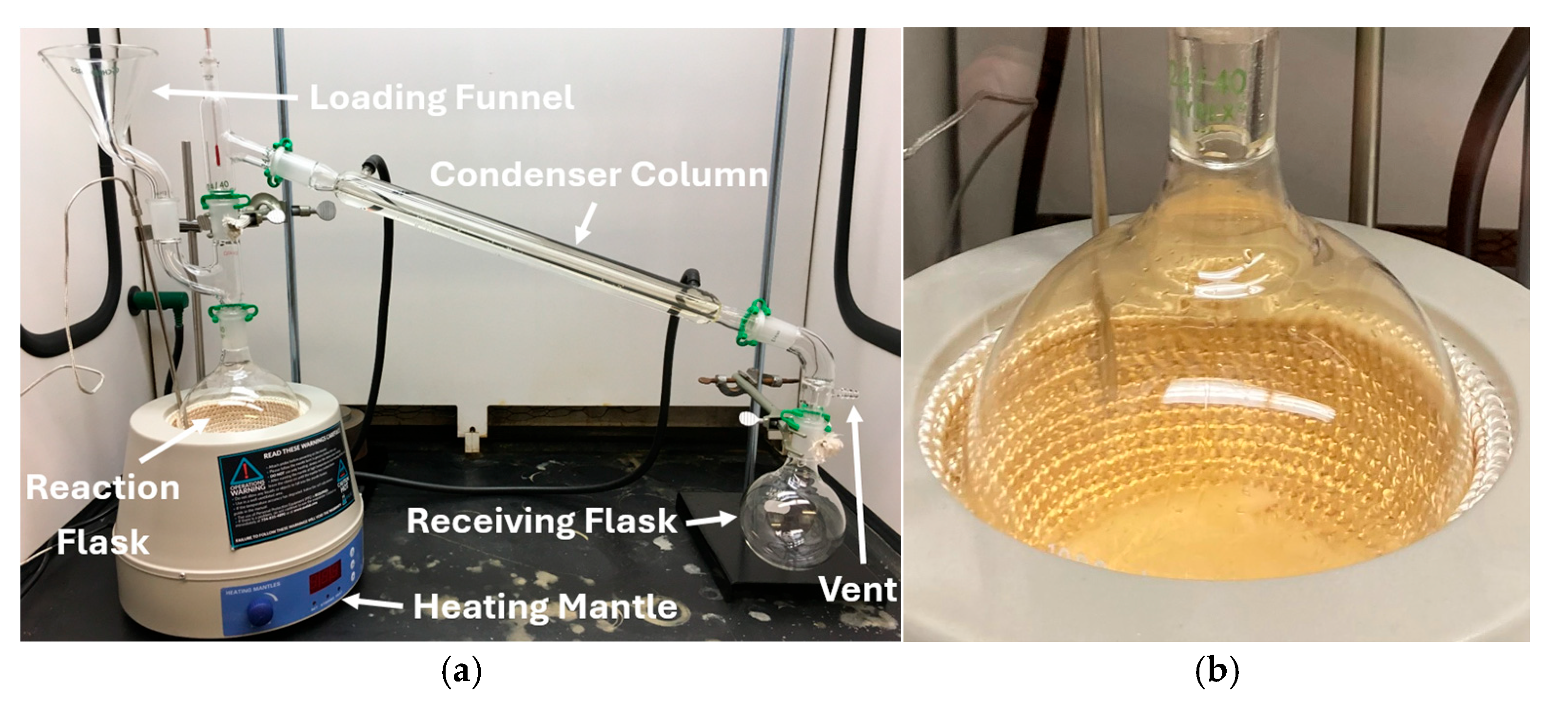
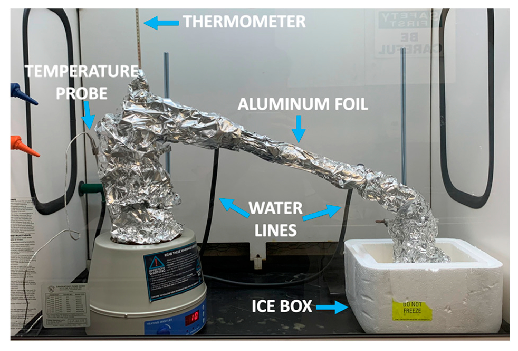
2.1. Lab Synthesis of WFNA

This study was accomplished through the development of a method to distill >99% pure WFNA from common off-the-shelf supplies (COTS) and the titration to determine the nitric acid (HNO3) weight percentage. An experimental distillation system was designed and assembled to combine the reactants, chosen as concentrated H2SO4 and a nitrate salt, to fabricate highly concentrated (>99% pure) WFNA. Photos of the WFNA distillation apparatus and distillation in progress are shown in Figure 1 and Figure 2.
For operator safety, the distillation process was performed under a fume hood. The best heating mantle and endpoint temperatures were evaluated first to make the most yield and concentration of the product solution. In the reaction flask, which laid in the heating mantle (shown in Figure 1), excess H2SO4 was combined with a nitrate salt and agitated with a stir bar to dissolve the salt. This helped the reactants heat uniformly. The H2SO4 was acquired from the supplier Alfa Aesar (CAS #7664-93-9). Sodium nitrate (NaNO3) and potassium nitrate (KNO3) were selected as nitrate salts. The salts were supplied by Sigma Aldrich (St. Louis, MO, USA); NaNO3 (CAS #7631-99-4) and KNO3 (CAS #7757-79-1). The reaction equation is provided in Equation (1):
H 2 S O 4 l + N a   o r   K N O 3 s H N O 3 g + N a   o r   K H S O 4 ( s )
Once distillation began, an orange-colored gas developed over the reactants (see Figure 1). This gas traveled into the condenser column above, signifying the creation of nitric acid. The temperature of the gas was measured by a thermometer located above the reaction flask. The product gas temperature stayed at 83 °C (which corresponded to the boiling point of anhydrous nitric acid) if the reaction was creating HNO3. A vent located on the bent distillation adapter above the receiving flask ensured no pressure build up in the apparatus, as this could lead to glassware rupture. To condense the gas to its liquid phase prior to collecting WFNA in the receiving flask, cold water was flowed through the condenser column. To cool the distilled WFNA, the receiving flask was submerged in an ice bath (see Figure 2). To prevent decomposition of the WFNA vapor when exposed to light, the entire system was wrapped in aluminum foil (see Figure 2). In addition, lights around the system were also turned off once the distillation process started. Distillation was halted when the desired endpoint temperature was reached on the thermometer above the reaction flask. Post-distillation, WFNA mass (m), volume (V), and liquid color were determined. The resultant WFNA was stowed in an amber, borosilicate glass bottle with a PTFE-lined cap. This was used to help reduce the chance of product decomposition as well as the product diffusing through the cap.
After distillation was complete, each batch of WFNA was titrated. The titration process was conducted no less than three times to ascertain the weight per weight concentration of HNO3. The initial and endpoint titration setups are shown in Figure 3.
To determine the concentration, a 50 mL burette was used to hold a titrant solution of ~1 M sodium hydroxide (NaOH) and de-ionized water (see Figure 3). A 50 mL analyte solution of ~1 M WFNA and deionized water was added to an Erlenmeyer flask. It should be noted that HNO3 is a monoprotic acid with NaOH. To improve the accuracy of the titration endpoint, both were diluted to ~1 M. To begin, three drops of phenolphthalein indicator were added to the analyte flask. The titration was conducted by slowly adding the drops of the titrant solution to the analyte flask until the analyte solution transformed from clear to a light pink color for at least 20 s (see Figure 3). A stir bar was used to mix the analyte solution throughout the titration process and the concentration of HNO3 in the WFNA was calculated.

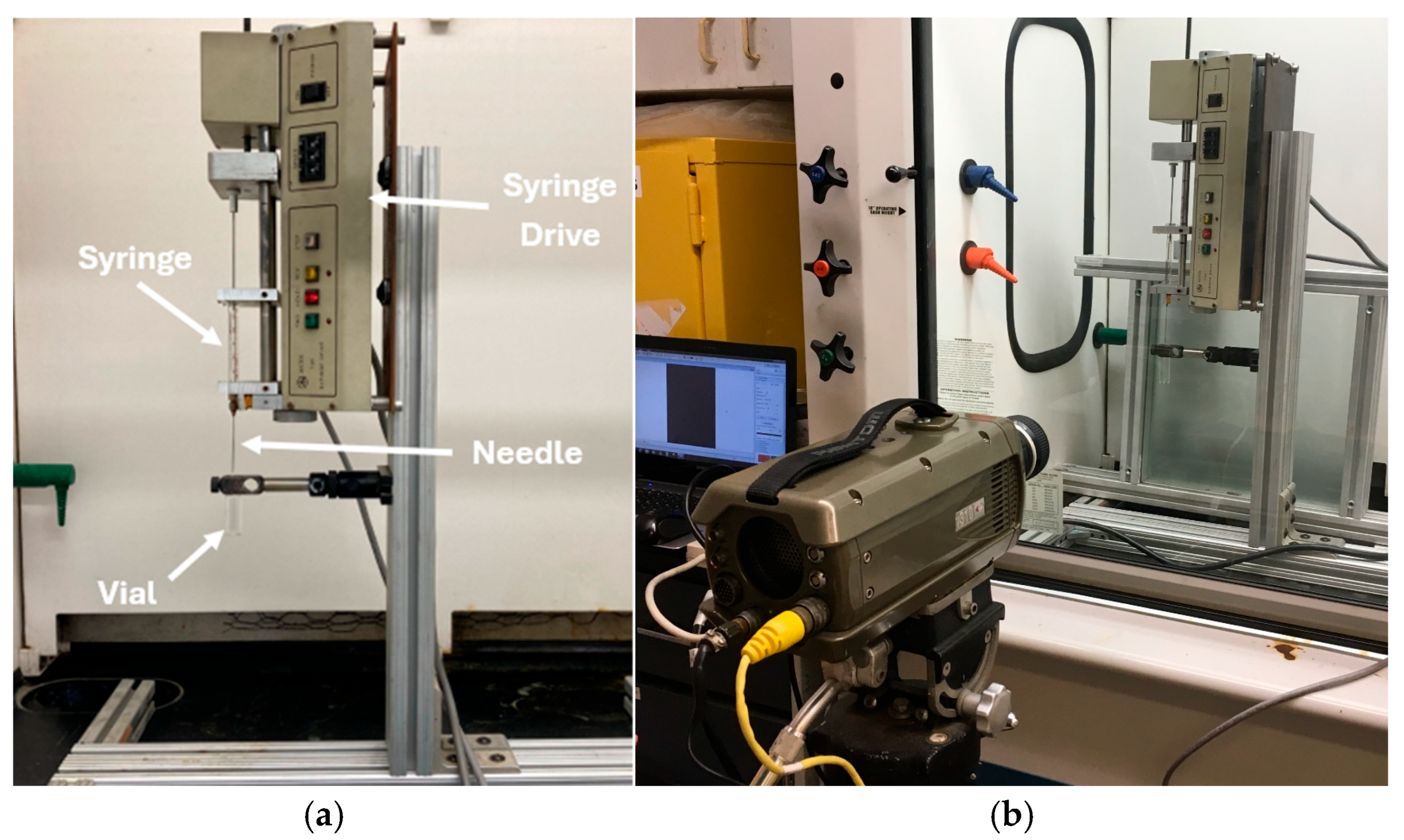
2.2. WFNA Droplet Testing Setup with TMEDA Fuel

A drop test apparatus was used to compare the average ignition delay times of both distilled WFNA and a batch of supplied WFNA oxidizer with 100% TMEDA fuel (five droplet tests per batch). Aside from the interest in additional water content on ignition delay time, the two concentrations of WFNA were evaluated due to availability and cost, with many suppliers discontinuing >99.5% WFNA and it being over five times the cost of >90% WFNA.
To perform the experiment, a 250 µL Hamilton 700 Series syringe equipped with a 20 gage, 50.8 mm needle was attached to an Antek 735 syringe drive. The syringe drive was operated using a custom LabVIEW program. When initiated, a single drop of TMEDA with a fixed volume (6.5 μL), was released 50 mm from the needle tip to a 100 μL pool of WFNA below. The syringe and syringe drive made for consistent evaluation of TMEDA droplets into WFNA and a syringe-type apparatus was common among droplet testing [11,25,26]. The consistent volume of each TMEDA drop corresponded to the volume at which the weight of the drop of TMEDA overcame the surface tension attaching it to the needle tip. The volume of the WFNA pool varied to compare ignition delay times. A Phantom v310 camera equipped with a 50 mm lens operating at 5000 frames per second was used to record the fuel drop being releasing from the syringe needle up to and through contact with WFNA and subsequent combustion. The entire apparatus and experiment, aside from the Phantom v310 camera, was housed inside a fume hood to contain the combustion byproducts and reduce air movement that may prematurely detach the fuel drop from the tip of the needle. After each experiment, the high-speed video was reviewed obtain the ignition delay time. For this study, the ignition delay time was identified as the time from the first contact of the TMEDA drop with the WFNA pool (t0) to first light when an ignition kernel appeared (tign) as defined in other hypergolic propellant droplet work [24,25,27,28,29]. A photograph of the ignition delay drop test system and high-speed cinematography setup is shown in Figure 4.

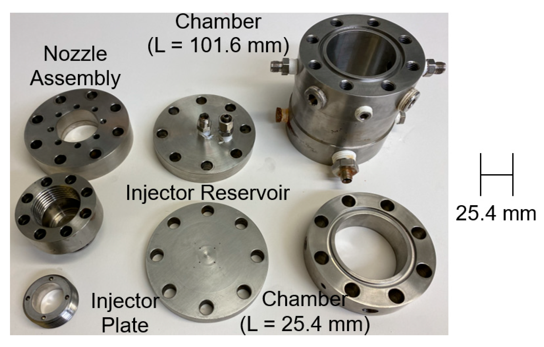
2.3. TMEDA/WFNA Hypergolic Bipropellant Rocket Engine Test Setup

In evaluating TMEDA as an alternative bipropellant rocket engine fuel the next step after droplet testing was to study TMEDA/WFNA combustion characteristics in a bipropellant rocket engine. To accomplish this, numerous bipropellant injector assemblies and a common, cylindrical combustion chamber assembly were designed and fabricated. The cylindrical shape provided an axisymmetric combustion chamber. The injectors, chamber assembly, and nozzle assembly were constructed from 316L corrosion resistant stainless steel (CRES). The material’s high strength allowed the engine to safely handle combustion products beyond 17.24 MPa psi. This value was determined by using a factor of safety of two on the predicted internal hoop stress for a maximum chamber pressure, PC, of 3.55 MPa. The combustion chamber outer diameter (OD) was 107.95 mm (with wall thickness of 23.98 mm). The chamber was fabricated with multiple access ports. These ports were used for pressure transducers (PT) to determine the instantaneous pressure in the combustion chamber as well as for gaseous nitrogen (GN2) for pre- and post-test purging. A cylindrical, cartridge-loaded medium-grade extruded graphite liner was placed inside the combustion chamber to house the combustion event and thermally protect the outer, metallic chamber walls. The graphite liners were maintained at a constant inner diameter (ID) of 34.93 mm and varied in length (L) to evaluate the effects of characteristic length (L*) on c* efficiency (ηc*). L* was initially selected at 0.38 m. Until empirical hot-fire data could be gathered and without knowing the combustion characteristics of TMEDA/WFNA in an engine, this initial L* value was selected based upon heritage liquid bipropellant rocket engines [4,5] and an existing combustion chamber [30]. Iso-molded fine graphite nozzle inserts were designed with a throat diameter of 9.53 mm in an atmospheric hot-fire environment (i.e., no expansion nozzle) to maintain a similar PC under similar mass flow of the reactants as well as limit the number of experimental parameters being evaluated in the test matrix. A schematic, exploded-view model can be seen in Figure 5.
To optimize and compare combustion results of TMEDA/WFNA in a rocket engine, multiple unlike-impinging injector configurations were designed based upon orifice size, oxidizer-to-fuel mixture ratio, MR, mass, momentum, and equivalence ratio, ϕ. At the same thrust (F) and PC levels, the differences in injector design allowed for the examination of combustion performance of TMEDA/WFNA in a rocket engine. These selected injector designs were compared against designs that did not have equal momentum ratios of the reactant streams, since studies by Rupe have shown this may not provide optimum mixing [31].
Two unlike doublet injectors (UD #1 and UD#2) each had four pairs of orifices, and the twin split triplet (TST) was an injector with a pair of triplets that used two oxidizer orifices as the center instead of one orifice [32]. These injectors combined with different L* permitted the evaluation of the TMEDA/WFNA mixtures in a heavyweight bipropellant rocket engine. Photos of the heavyweight bipropellant rocket engine components, graphite chamber lines, and examples of the impinging jet streams (using distilled water) for an impinging UD #1 injector and TST injector can be seen in Figure 6, Figure 7 and Figure 8.
As observed in Figure 8, the UD injectors utilize angled streams (30° half angle) of TMEDA impinging with angled streams (30° half angle) of WFNA. The orifice diameters for UD #1 injector design were 0.51 mm (TMEDA) and 0.76 mm (WFNA). The UD #1 injector design was based on an ideal mixing ratio of TMEDA and WFNA, while the UD #2 injector design was based on an ideal Rupe number, with 0.38 mm TMEDA orifice diameters and 0.84 mm WFNA orifice diameters. The TST injector was designed using four, 60° half angle TMEDA streams (0.38 mm orifice diameters) to impinge on four, straight (no half angle) WFNA streams (0.84 mm orifice diameters) at separate points, and the momentum of the TMEDA streams on the WFNA streams caused the four separate impingements to meet each other at a common, secondary point. All the injector orifices were designed for a length-to-diameter, L/D, of 20 and orifice diameters were selected based upon similar ranges used in non-toxic hypergolic propellant literature [24,28,29].
Due to the small propellant quantities and availability of stored gas, a gas-pressurized propellant feed system was selected to drive the liquid reactants as well as supply internal, gaseous purge. GN2 was used as both the valve pressurant and purge gas due to low cost and availability. Two separate 304L CRES reservoirs (tank volume = 3.79 × 10⁻³ m3) were used to store TMEDA and WFNA. A hand valve (HV) at the reservoir inlet was installed to provide access to fill the reservoirs with the desired amount of reactants pre-test as well as the ability to vent the reservoirs post-test. Typical amounts of fuel and oxidizer loaded for a test series of three to five hot-fire experiments (test times ranged from 3 to 6 s) ranged from 2.00 × 10⁻⁴ m3 to 5.00 × 10⁻⁴ m3. The volume of reactants loaded was based upon reactants being delivered/stored in 5.00 × 10⁻⁴ m3 containers prior to loading and the desire to perform many tests per injector with the reactant supplies. Downstream of reservoirs, a pneumatic actuated 3-way ball valve (BV) was utilized to initiate fluid flow (30 ms opening response time). When the normally closed portion of the BV was initiated, each reactant would travel through a 6.35 mm OD flexible stainless-steel hose, through a check valve (0.007 MPa cracking pressure), and into the injector assembly. The other path through the BV was connected to a water purge line and GN2 purge valves, used to safely purge the reactants and the combustion products out of the feed system and engine post-test. Prior to an experiment, each reactant reservoir regulator was adjusted to a desired feed pressure Pfeed. The opening and closing of the BVs, as well as the sequencing of the GN2 purge events, were controlled by a custom LabVIEW program.
For diagnostic instruments, a 200 N load cell (Omega Engineering, Inc., Norwalk, CT, USA, Model LCMKD-200N) was used to measure thrust at a sampling rate of 1000 Hz. The load cell was in contact with the thrust stand, which housed the bipropellant rocket engine on an engine mounting platform that used two linear guide rails, each with two pillow blocks that allowed the engine to slide axially during firing. Since the bipropellant rocket engine was mounted vertically to the engine mounting platform, to maintain contact with the load cell pre-test, compression springs installed on the linear guide rails were used to counteract the weight of the engine (engine weight ranged from 6.8 to 15.4 kg). Static PT measured reservoir (Setra Model 206, 0–3.55 MPa range), feed (Setra Model 206, 0–3.55 MPa range), and PC (Setra Model 206, 0–1.83 MPa range) at 1000 Hz over a test time of 25 s. Video cinematography of the combustion plume was ascertained along with PC measurements to determine the stability of the combustion event. A schematic showing the TMEDA/WFNA bipropellant rocket engine system and photographs of the pressure-fed fluid delivery system and hypergolic bipropellant rocket engine can be seen in Figure 9 and Figure 10, respectively.

3. Results and Discussion

A series of droplet and engine hot-fire experiments were conducted using the drop test system and an instrumented hypergolic heavyweight bipropellant rocket engine. The experimental results of the tests conducted thus far are presented below.

3.1. WFNA Droplet Testing with TMEDA Fuel

Fourteen batches of WFNA were distilled and the average ignition delay time with 100% TMEDA fuel was determined from droplet testing. The parameters that were controlled during the experiments included the nitrate salt (NaNO3 or KNO3), the reactant mass (or batch size), the heating mantle temperature, and the thermometer endpoint (or stopping) temperature. The experimental parameters of interest included the weight per weight mass concentration of HNO3 in the WFNA, the batch percent yield, and the average ignition delay time. Also, nitrogen oxide concentration in the distilled WFNA was of interest since this quantity distinguishes WFNA from RFNA; only WFNA is non-toxic. To determine this, the color of the distilled WFNA was observed. For large amounts of nitrogen oxides, a dark orange color will be seen whereas a tinted yellow color will represent minimal nitrogen oxides (shown in Figure 11). The authors attempted to send off the distilled WFNA samples to a laboratory to obtain a value for the nitrogen oxide concentration. Unfortunately, no laboratory could be located that could perform such analyses. Experimental WFNA distillation data is shown in Table 1.
Based upon Table 1, it was observed that Batch 4 was distilled at the lowest mantle temperature (85 °C). This led to the worst percent yield (18.38%), the highest concentration (101.67%), and the fastest ignition delay time (10.92 ms). It was hypothesized that this was the result of Batch 4 being a dark orange color whereas the other 13 batches were light yellow in color. This indicated a larger amount of nitrogen oxides in Batch 4. Compared to the other batches, Batch 4 experienced the lowest mantle temperature, which is believed to have led to a lower production rate of HNO3 vapor and a longer time to move from the reaction flask to the condenser column. The gaseous phase of HNO3 is particularly sensitive to decomposition, so the increased time for the vapors to move from the reaction flask to the condenser column allowed more of the nitric acid vapors to decompose to nitrogen oxides. The large amount of nitrogen oxides in Batch 4 (with a molar mass greater than that of HNO3) led to skewed titration concentration results because nitrogen dioxide (NO2) and N2O4 react with NaOH just as HNO3 does. N2O4 (formed through the decomposition of nitric acid) is highly reactive, less stable, and more reactive than HNO3, which helps to explain the reduced ignition delay time. With ignition delay time not being a function of the quantities calculated in this study, it is believed that another factor, such as the concentration of dissolved nitrogen oxides may be influencing ignition delay time. Although a quicker ignition delay time is desired for a hypergolic oxidizer (for long ignition delay times of hypergolic propellant may lead to hard starts and combustion instability [12]), N2O4 is highly toxic, carcinogenic, and lethal to humans.
For batches that had a stopping temperature at 45 °C, percent yield, mass concentration HNO3, and mantle temperature are shown in Figure 12. Based upon Figure 12 and Table 1, Batch 14 had the highest mass concentration of 99.94% and a percent yield of 90.14%. Despite the high concentration, Batch 14 exhibited the second-slowest ignition delay time of 15.96 ms (while also having the lowest mantle temperature, 115 °C, of these batches). For comparison, Batch 8 saw the greatest percent yield of 92.72% and the second-greatest mass concentration of 98.76% (mantle temperature, 130 °C). Furthermore, with an average ignition delay time of 13.28 ms, only Batch 6 was quicker at 11.72 ms. For the highest mantle temperature of 135 °C, Batches 9 and 12 resulted in the lowest mass concentrations and percent yields.
For batches that had a mantle temperature at 130 °C, percent yield, mass concentration HNO3, and stopping temperature are shown in Figure 13. The stopping temperature was the thermometer temperature of the HNO3 vapor when the distillation process ended (i.e., nitrate salt consumed by the reaction). A question may be presented as to why the researchers did not stop the distillation process once the thermometer reached room temperature. The reason is that HNO3 is a hygroscopic liquid and will absorb atmospheric water vapor. Since the distillation system has a vent open to atmosphere to remove any pressure building within the glassware, it was hypothesized by the researchers that the concentration of the WFNA would decrease as the reaction progressed due to additional absorption of atmospheric water vapor. Naturally, the percent yield increases as the reaction progresses; therefore, determining the best combination of mantle temperature and stopping temperature was important to maximize mass concentration and percent yield.
Based upon Figure 13, it was observed that the greatest ending temperature was associated with the greatest mass concentration and the lowest percent yield. A trend occurred where mass concentration decreased with ending temperature decrease (i.e., reaction progresses) and percent yield increased with ending temperature decrease. Additionally, there were similar results for mass concentration and percent yield among KNO3 batches ending at 61 °C and 46 °C. The 46 °C batch had an average ignition delay time 1.56 ms quicker than the 61 °C batch.
A series of photos showing the advancement of a droplet test to measure the ignition delay time of TMEDA/WFNA is shown in Figure 14. The arrows provided show the TMEDA droplet entering and contacting the WFNA pool (Figure 14a,b) and the point of first light (Figure 14d). The time to flame propagation was +21.0 ms after TMEDA contacted the WFNA pool, with tign = +16.6 ms.
A batch of >99.5% WFNA (purchased from Sigma Aldrich) was droplet-tested along with the fourteen distilled batches of WFNA to find the average ignition delay time for TMEDA/WFNA. Every distilled batch of WFNA except Batch 1 exhibited a quicker average ignition delay time than the supplied WFNA, which resulted in an average ignition delay time of 17.48 ms. Ignition delay time and salt density as a function of HNO3 mass concentration are provided in Figure 15 for HNO3 mass concentrations above 98%. Based upon Figure 15, there is a positive relationship between mass concentration and density. It is believed that this behavior may be related to the concentration of nitrogen oxides in the distilled WFNA falsely adding to the mass concentration of HNO3. A thorough chemical analysis is recommended to separately quantify these mass concentrations. Overall, all formulations of WFNA tested with 100% TMEDA resulted in tign < 20 ms. Therefore, based on the ignition delay results, hot-fire experiments in a heavyweight bipropellant rocket engine would be conducted using 100% TMEDA.

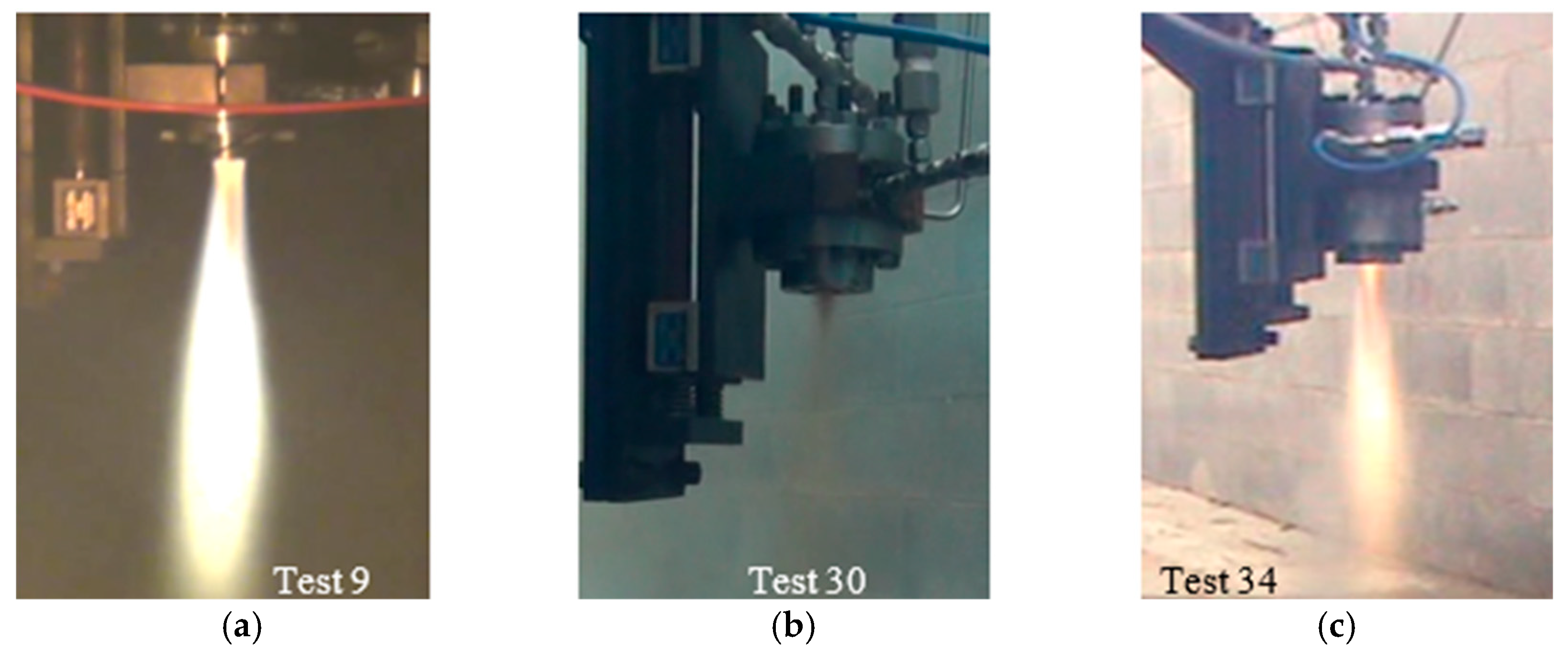
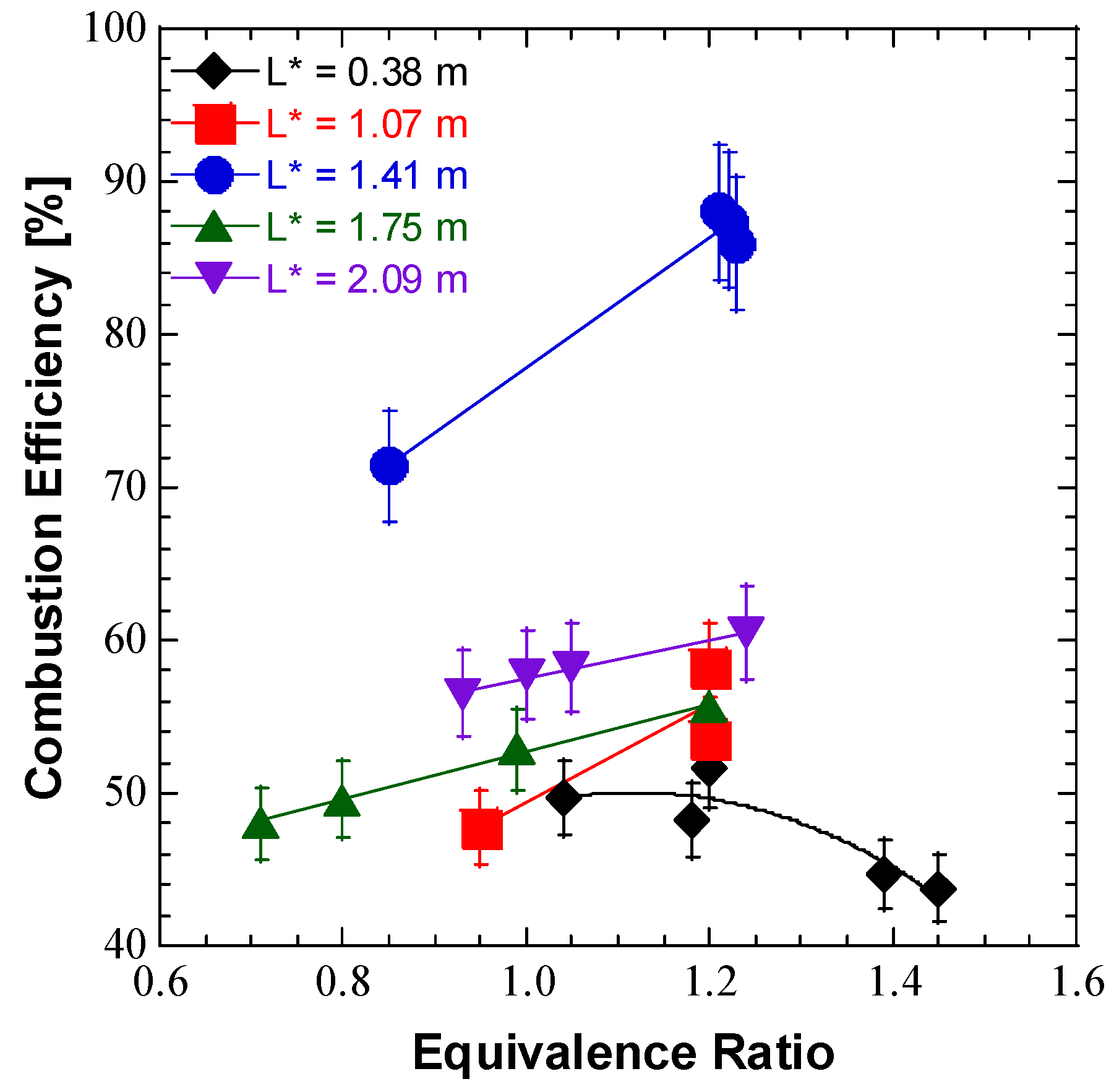
3.2. TMEDA/WFNA Hypergolic Bipropellant Rocket Engine Testing

Fifty TMEDA/WFNA hot-fire experiments were performed using a hypergolic heavyweight bipropellant rocket engine while varying the injector design and reactant mass flow rates. Three injectors, along with five different L*, were evaluated over a wide range of ϕ. Injector design and chamber geometry effects were observed on combustion performance. The experimental test series was divided into two areas. The first evaluated TMEDA/>99.5% WFNA with the same L*, only varying injectors over 26 experiments. The second evaluated TMEDA/>90% WFNA with varying L* and injectors over 24 experiments.
Before being used in a hot-fire experiment, all the injectors were installed on a cold-flow water flow stand to determine the fuel and oxidizer mass flow rates at various Pfeed and optically verify the exiting streams were impinging on their centers using video cinematography (recorded at 30 frames per second). These measurements were compared to the calculated, ideal mass flow rates from the injector designs to screen each injector and determine whether each injector emulated the theoretical performance of the design. An example of the experimental and theoretical pressure drops with mass flow rate for UD #1 injector design is shown in Figure 16. Minor deviations in injector pressure drop for the fuel circuit at greater mass flow rates may be attributed to cavitation in the fuel circuit due to sharp edge orifices and no back pressure used in the cold-flow test apparatus.
All three injector designs achieved ignition and combustion in the heavyweight bipropellant rocket engine during hot-fire testing. The combustion efficiency (ηc*) of each hot-fire test was calculated based on c* [4,5] using measured data from each test, seen in Equation (2).
c * = P C · A t
Data from each test was used in Equation (2) to calculate an experimental c* value. Also, from the test data, an experimental ϕ was calculated in Equation (3), using a value of 4.35 as the MR of the TMEDA/WFNA reactants under stoichiometric conditions.
ϕ = T M E D A W F N A 1 4.35
The experimental MR and ϕ were then used with NASA-CEA code to determine the theoretical maximum c* value for the conditions of each hot-fire test [33]. Finally, the experimental c* value was evaluated against the theoretical c* value to give the ηc* of the experiment using Equation (4).
η c * = c e x p * c t h e o r *
Photographs of some TMEDA/WFNA engine hot fires can be seen in Figure 17.
Overall, the first hot-fire test series using TMEDA/>99.5% WFNA and a constant L* of 0.38 m covered a ϕ and PC range of 0.59–1.44 and 0.10–1.04 MPa, respectively. Representative test runs of each injector design along with measured and calculated results are shown in Table 2 (Note: Test 3 did not have a load cell installed to measure thrust). These specific test runs were selected to highlight the effects of similar ϕ for each injector design on ηc*. Even though L* was constant for these experiments, it was clear that this L* value did not provide enough volume for reactant mixing to stay in the combustion chamber, resulting in ηc* < 50% for the UD #1 and TST injector designs under fuel-lean reactant flow conditions. Greater performance was achieved when fuel-rich conditions were fired, with UD #2 injector design providing better mixing of the reactant streams in the small chamber volume when compared to the other injectors at similar ϕ and L*.
The second series of testing using TMEDA/>90% WFNA with varying L* covered a ϕ and PC range of 0.71–1.45 and 0.42–0.97 MPa, respectively. Representative test runs of each injector design along with measured and calculated results are shown in Table 3 (Note: Tests 36 and 44 ran out of propellant during the hot-fire experiment due to underloading of reservoirs from the previous test and did not provide steady-flow data; Tests 32 and 33 did not have load cell aligned properly with engine).
From the experimental results displayed in Table 3, it was observed that by increasing L*, the additional volume provided increased residence time (stay time) for the reactants to mix, leading to more complete combustion and an increase of over 30% in ηc* for some ϕ. For example, a maximum ηc* of 88.0% at a PC of 0.96 MPa was recorded for an L* of 1.41 m with a ϕ of 1.21. For similar ϕ (ϕ = 1.20), a slight decrease in L* to 1.07 m dropped ηc* to a maximum of 58.2% while a slight increase to 1.75 m (ϕ = 1.20) decreased the ηc* to a maximum of 55.6%. This indicated that while increased volume helped reactant mixing and increased combustion performance to a certain point, beyond an optimum L* value increased length resulted in a drop in ηc* from the excess volume and heat loss, which corresponded well with other hypergolic reactant mixtures L* outcomes [4,5].
Over the entire range of L* values, the worst ηc* of 43.8% was recorded at an L* of 0.38 m, which was a function of ϕ as much as L*. To further highlight the effect of L* on combustion performance, calculated ηc* values for various ϕ for both UD injector designs are shown in Figure 18. It was observed that for UD #1 injector design, the best mixing and combustion performance occurred at a L* of 1.41 m. For all the tests shown in Figure 18, a decrease in ηc* at each L* value corresponded to more fuel-lean reactant flows. As observed in Table 2, no matter what the %WFNA oxidizer, ϕ had an influence in the combustion performance results, where slightly fuel-rich mixtures generated better mixing and engine performance than stoichiometric or fuel-lean mixing conditions. This was shown in Figure 19, where ηc* tended to increase for each L* of UD #1 injector design as ϕ increased, moving from a fuel-lean to fuel-rich mixture. For low L*, such as 0.38 m, as ϕ increased beyond 1.2, ηc* decreased, showing how the lack of residence time in the chamber hindered the reaction. The experimental results from Table 2 and Table 3 also showed that utilizing the same engine configuration (UD #1 injector design and L* of 0.38 m) and similar ϕ values near unity in Test 3 and Test 31, ηc* was 71.1% for the >99.5% WFNA and 51.6% for the >90% WFNA. As was expected under similar flow, PC, and L* conditions, the >99.5% WFNA provided better combustion performance.
Experimental pressures, F, and MR traces with time for hot-fire Tests 31 and 34 are given in Figure 20. For comparison, each of these selected hot-fire experiments used the same injector design (UD #1) over a minimum test duration of 3 s for nearly the same measured ϕ and PC. The ηc* for Test 34 was over 36% greater than that of Test 31; L* was over 3.7 times greater as well. Another interesting observation was that the reactant pressure drops across the injector were much larger for Test 31. This indicated that more reactants were being mixed and burned for Test 34. To achieve the same PC, Test 31 required more reactant flow (over 35 g/s more), and a portion of unburned reactants exited the nozzle, leading to reduced ηc*.

3.3. Future Directions

For future research, the authors plan to conduct hot-fire experiments of TMEDA/WFNA while adding spacers to vary the length of the engine to determine whether an increase in mixing and residence time will increase the efficiency of the engine using different injector designs. Testing with additional injector designs (i.e., pentad and different orifice sizes) but have yet to be installed on the engine during a hot-fire test, are also planned. Also, conducting hot-fire experiments using TMEDA/WFNA with additively manufactured injectors to compare combustion performance of additively manufactured injectors against conventionally machined injectors of the same design are desired to be examined. The authors plan to continue the distillation process of WFNA with an eye on scaling up production to help support TMEDA/WFNA hot-fire testing. Other areas of interest include batch size. Lastly, the authors would like to evaluate the aging effects on distilled WFNA.

4. Conclusions

A study was performed to evaluate ignition delay times and combustion performance for different percentages of WFNA with 100% TMEDA. Distilled WFNA was fabricated at >99.5% mass concentration using nitrate salt (both NaNO3 and KNO3) combined with concentrated sulfuric acid. No significant differences in performance were seen among the nitrate salts, with NaNO3 being favored due to its low cost and lower molar mass. A percent yield >90% was only achieved with a stopping temperature of 45 °C. The percent yield was observed to increase as the reaction progressed, in conjunction with a decrease in stopping temperature. Omitting Batch 4, the highest mass concentration of 99.98% was achieved with a mantle temperature of 130 °C. Both the >99.5% and >90% WFNA produced ignition delay times from droplet testing were under 20 ms. Distilled WFNA (except Batch 1) demonstrated quicker average ignition delay times than the supplied >99.5% WFNA. The faster ignition delay times were due to an excess of N2O4 dissolved in the distilled WFNA. Batch size did not appear to affect the quality of the final product.
An experimental pressure-fed fluid delivery system and hypergolic heavyweight bipropellant rocket engine were designed, fabricated, and successfully ignited and combusted with TMEDA/WFNA. Multiple injector designs with various injector elements, orientations, and orifice diameters were evaluated to characterize TMEDA/WFNA combustion performance. It was found that TMEDA with >99.5% WFNA generated greater PC and ηc* than TMEDA with >90% WFNA for the same engine configuration and ϕ. An evaluation of engine L* showed that ηc* increased with L* due to the increased residence time for the reactants to mix and achieve more complete combustion. ηc* increased by over 30% from an L* value of 0.38 m to a value of 1.41 m; however, a further increase in L* resulted in decreased ηc* due to additional volume and heat loss. At an L* of 1.41 m, a maximum ηc* of 88.0% was recorded with UD #1 injector design. Additionally, slightly fuel-rich mixtures produced greater ηc* values than stoichiometric and fuel-lean mixtures at the same L*. With increased L* and an optimized injector, an increase in ηc* is expected, showing TMEDA/WFNA may be a viable alternative to equivalent low-thrust, toxic, and hypergolic bipropellant rocket engines.

Author Contributions

Conceptualization, J.D.M. and G.A.R.; methodology, J.M.H., M.L.L.I., J.D.M. and G.A.R.; software, G.A.R.; validation, J.M.H., M.L.L.I., J.D.M. and G.A.R.; formal analysis, J.M.H., M.L.L.I., J.D.M. and G.A.R.; investigation, J.M.H., M.L.L.I., J.D.M. and G.A.R.; resources, J.D.M. and G.A.R.; data curation, J.M.H., M.L.L.I., J.D.M. and G.A.R.; writing—original draft preparation, J.M.H., M.L.L.I., J.D.M. and G.A.R.; writing—review and editing, J.D.M. and G.A.R.; visualization, J.D.M. and G.A.R.; supervision, J.D.M. and G.A.R.; project administration, J.D.M. and G.A.R.; funding acquisition, J.D.M. and G.A.R. All authors have read and agreed to the published version of the manuscript.

Funding

This research was internally funded by the Research and Sponsored Program Office at Penn State Altoona and Mr. Corey Gracie-Griffin, Associate Dean of Research, grant number RDG.

Data Availability Statement

The raw data supporting the conclusions of this article will be made available by the authors on request.

Acknowledgments

The authors would like to acknowledge Tim Deibler and Deibler Machining for machining the rocket engine injector plates. Thanks to Tom Hatch, Russ Heaton, and Jonathan Hileman of Penn State Altoona for fabrication of the 316L CRES chambers. Thanks to Dillon Over of Penn State Altoona for machining graphite liners and nozzles and to Benjamin Smith of Penn State Altoona for initial assembly and test firing assistance. The authors would like to also thank the Penn State Altoona chemistry department, in particular Richard Bell, Lynn Dalby, and Dana Brinkel, and for use of equipment and advice.

Conflicts of Interest

The authors declare no conflicts of interest. The funders had no role in the design of the study; in the collection, analyses, or interpretation of data; in the writing of the manuscript; or in the decision to publish the results.

Abbreviations

The following abbreviations are used in this manuscript:
BVBall valve
CRESCorrosion-resistant stainless steel
c*Characteristic velocity [m/s]
DDiameter [mm]
DMAZ2-N,N-dimethylaminoethylazide
FThrust [N]
GN2Gaseous nitrogen
HVHand valve
HNO3Nitric acid
H2SO4Sulfuric acid
IDInner diameter [mm]
IspSpecific impulse [s]
KNO3Potassium nitrate
LLength [mm]
L/DLength-to-diameter ratio of injector orifice
L*Characteristic length [m]
mMass [g]
MMHMonomethylhydrazine
MONMixed oxides of nitrogen
MROxidizer-to-fuel mixture ratio
NaNO3Sodium nitrate
NaOHSodium hydroxide
N2H4Hydrazine
NO2Nitrogen dioxide
N2O4Nitrogen tetroxide
ODOuter diameter [mm]
PCChamber pressure [MPa]
PfeedReactant feed pressure [MPa]
PTPressure transducer
RFNARed fuming nitric acid
t0Time oxidizer and fuel streams initiate impingement [ms]
tignTime of first light subsequent impingement [ms]
TMEDAN,N,N′,N′-tetramethylethylenediamine
TSTTwin split triplet
UDUnlike doublet
VVolume [mL]
WFNAWhite fuming nitric acid
ηc*c* efficiency
ϕEquivalence ratio
ρDensity [g/mL]

References

  1. Clark, J.D. Ignition! An Informal History of Liquid Rocket Propellants; Rutgers University Press: New Brunswick, NJ, USA, 1972; pp. 7–73. [Google Scholar]
  2. Schalla, R.L.; Fletcher, E.A. The Ignition Behavior of Various Amines with White Fuming Nitric Acid; Lewis Research Center, NASA: Cleveland, OH, USA, 1959.
  3. Coil, M.A. Hypergolic Ignition of a Gelled Ionic Liquid Fuel. In Proceedings of the 46th AIAA/ASME/SAE/ASEE Joint Propulsion Conference & Exhibit, Nashville, TN, USA, 25–28 July 2010. [Google Scholar] [CrossRef]
  4. Huzel, D.K.; Huang, D.H. Modern Engineering for Design of Liquid-Propellant Rocket Engines; Progress in Astronautics and Aeronautics; American Institute of Aeronautics and Astronautics, Inc.: Reston, VA, USA, 1992; Volume 147, pp. 1–431. [Google Scholar] [CrossRef]
  5. Sutton, G.P.; Biblarz, O. Rocket Propulsion Elements, 7th ed.; John Wiley & Sons, Inc.: New York, NY, USA, 2001; pp. 234–235. [Google Scholar]
  6. Sutton, G.P. History of Liquid Propellant Rocket Engines; American Institute of Aeronautics and Astronautics, Inc.: Alexandria, VA, USA, 2006; pp. 5–21. [Google Scholar]
  7. Wang, S.; Thynell, S.T.; Chowdhury, A. Experimental Study on Hypergolic Interaction between N,N,N′,N′-Tetramethylethylenediamine and Nitric Acid. Energy Fuels 2010, 24, 5320–5330. [Google Scholar] [CrossRef]
  8. Zhang, Q.; Shreeve, J.M. Ionic Liquid Propellants: Future Fuels for Space Propulsion. Chem. Eur. J. 2013, 19, 15446–15451. [Google Scholar] [CrossRef] [PubMed]
  9. AIAA SP-084-1999; Fire, Explosion, Compatibility, and Safety Hazards of Hypergols—Hydrazine. American Institute of Aeronautics and Astronautics, Inc.: Reston, VA, USA, 1999; pp. 1–150.
  10. Gohardani, A.S.; Stanojev, J.; Demaire, A.; Anflo, K.; Persson, M.; Wingborg, N.; Nilsson, C. Green Space Propulsion: Opportunities and Prospects. Prog. Aerosp. Sci. 2014, 71, 128–149. [Google Scholar] [CrossRef]
  11. Kang, H.; Kwon, S. Experiment and Speculations on Nontoxic Hypergolic Propulsion with Hydrogen Peroxide. Spacecr. Rocket. 2018, 55, 1230–1234. [Google Scholar] [CrossRef]
  12. Kang, H.J.; Lee, E.K.; Kwon, S.J. Suppression of Hard Start for Nontoxic Hypergolic Thruster Using H2O2 Oxidizer. J. Propuls. Power 2017, 33, 1111–1117. [Google Scholar] [CrossRef]
  13. Sackheim, R.L.; Masse, R.K. Green Propulsion Advancement: Challenging the Maturity of Monopropellant Hydrazine. J. Propuls. Power 2014, 30, 265–276. [Google Scholar] [CrossRef]
  14. Larsson, A.; Wingborg, N. Green Propellants Based on Ammonium Dinitramide (ADN). In Advances in Spacecraft Technologies; Hall, J., Ed.; InTech: Rijeka, Croatia, 2011; pp. 139–156. [Google Scholar]
  15. Spores, R.A.; Masse, R.L.; Kimbrel, S.; McLean, C. GPIM AF-M315E Propulsion System. In Proceedings of the 49th AIAA/ASME/SAE/ASEE Joint Propulsion Conference, San Jose, CA, USA, 14–17 July 2013. [Google Scholar] [CrossRef]
  16. Chambreau, S.D.; Schneider, S.; Rosander, M.; Hawkins, T.; Gallegos, C.J.; Pastewait, M.F.; Vaghjiani, G.L. Fourier Transform Infrared Studies in Hypergolic Ignition of Ionic Liquids. J. Phys. Chem. A 2008, 112, 7816–7824. [Google Scholar] [CrossRef] [PubMed]
  17. Schneider, S.; Hawkins, T.; Rosander, M.; Vaghjiani, G.; Chambreau, S.; Drake, G. Ionic Liquids as Hypergolic Fuels. Energy Fuels 2008, 22, 2871–2872. [Google Scholar] [CrossRef]
  18. He, L.; Tao, G.H.; Parrish, D.A.; Shreeve, J.M. Nitrocyanamide-Based Ionic Liquids and Their Potential Applications as Hypergolic Fuels. Chem. Eur. J. 2010, 16, 5736–5743. [Google Scholar] [CrossRef] [PubMed]
  19. Thompson, D.M. Tertiary Amine Azides in Hypergolic Liquid or Gel Fuels Propellant Systems. U.S. Patent 6013143A, 11 January 2000. [Google Scholar]
  20. Stevenson, W.H.; Felton, L.D.; Wang, Z.S. Hypergolic Liquid or Gel Fuel Mixtures. U.S. Patent 0,127,551A1, 5 June 2008. [Google Scholar]
  21. McQuaid, M.J.; Stevenson, W.H.; Thompson, D.M. Computationally Based Design and Screening of Hypergolic Multiamines; Technical Report, NTIS No. ADA433347; US Army Research Laboratory: Aberdeen Proving Ground, MD, USA, 2004. [Google Scholar]
  22. Stevenson, W.H.; Felton, L.D.; Wang, Z.S. Hypergolic Liquid or Gel Fuel Mixtures. U.S. Patent 0272071, 10 November 2011. [Google Scholar]
  23. McQuaid, M.J. Computational Characterization of 2-Azidocycloalkanamines: Notional Variations on the Hypergol 2-Azido-N,N-Dimethylethanamine (DMAZ); ARL-TR-2806; Army Research Laboratory: Aberdeen Proving Ground, MD, USA, 2002. [Google Scholar]
  24. Bittner, D.E.; Sell, J.L.; Risha, G.A. Effect of Jet Momentum Ratio and Equivalence Ratio on the Ignition Process of TMEDA and White Fuming Nitric Acid (WFNA). In Proceedings of the 49th AIAA/ASME/SAE/ASEE Joint Propulsion Conference, San Jose, CA, USA, 14–17 July 2013. [Google Scholar] [CrossRef]
  25. Kang, H.J.; Kwon, S.J. Green Hypergolic Combination: Diethylenetriamine-Based Fuel and Hydrogen Peroxide. Acta Astronaut. 2017, 137, 25–30. [Google Scholar] [CrossRef]
  26. Kang, H.; Park, S.; Park, Y.; Lee, J. Ignition-Delay Measurement for Drop Test with Hypergolic Propellants: Reactive Fuels and Hydrogen Peroxide. Combust. Flame 2020, 217, 306–313. [Google Scholar] [CrossRef]
  27. Kang, H.; Jang, D.; Kwon, S. Demonstration of 500 N Scale Bipropellant Thruster using Non-Toxic Hypergolic Fuel and Hydrogen Peroxide. Aerosp. Sci. Technol. 2016, 49, 209–214. [Google Scholar] [CrossRef]
  28. Connell, T.L.; Risha, G.A.; Yetter, R.A.; Natan, B. Ignition of Hydrogen Peroxide with Gel Hydrocarbon Fuels. J. Propuls. Power 2018, 34, 170–181. [Google Scholar] [CrossRef]
  29. Pourpoint, T.L.; Anderson, W.E. Hypergolic Reaction Mechanisms of Catalytically Promoted Fuels with Rocket Grade Hydrogen Peroxide. Combust. Sci. Technol. 2007, 179, 2107–2133. [Google Scholar] [CrossRef]
  30. Sell, J.L.; Bittner, D.E.; Koeck, J.J.; Risha, G.A. Design, Fabrication, and Ground Test of a Hydrocarbon Rocker Engine. In Proceedings of the 49th AIAA/ASME/SAE/ASEE Joint Propulsion Conference, San Jose, CA, USA, 14–17 July 2013. [Google Scholar] [CrossRef]
  31. Rupe, J.H. A Correlation Between the Dynamic Properties of a Pair of Impinging Streams and the Uniformity of Mixture-Ratio Distribution in the Resulting Spray; Progress Report No.20-209; Jet Propulsion Laboratory, California Institute of Technology: Pasadena, CA, USA, 1956. [Google Scholar]
  32. Nusca, M.J.; Mathis, N.P.; Michaels, R.S. Reacting Flow CFD Model of Throttling in the Army’s Impinging Stream Vortex Engine. In Proceedings of the 44th AIAA/ASME/SAE/ASEE Joint Propulsion Conference, Hartford, CT, USA, 21–23 July 2008. [Google Scholar] [CrossRef]
  33. McBride, B.J.; Gordon, S. Computer Program for Calculation of Complex Chemical Equilibrium Compositions and Applications; NASA Reference Publication 1311; Lewis Research Center, NASA: Cleveland, OH, USA, 1994.
Figure 1. Photos of distillation: (a) Glassware orientation for loading of reactants; (b) Orange-colored gas above the reactants at start of distillation.
Fuels 06 00058 g001
Figure 2. Photo of distillation of WFNA in progress.
Fuels 06 00058 g002
Figure 3. Photos of the titration setup to determine concentration: (a) Initial; (b) Endpoint.
Fuels 06 00058 g003
Figure 4. Photo of the TMEDA/WFNA: (a) experimental drop test system; (b) high-speed cinematography setup.
Fuels 06 00058 g004
Figure 5. Schematic of TMEDA/WFNA experimental bipropellant rocket engine.
Fuels 06 00058 g005
Figure 6. Photo of TMEDA/WFNA experimental bipropellant rocket engine components.
Fuels 06 00058 g006
Figure 7. Photo of TMEDA/WFNA experimental bipropellant rocket engine graphite liners.
Fuels 06 00058 g007
Figure 8. Photos of injector jet stream impingement with distilled water: (a) UD #1; (b) TST.
Fuels 06 00058 g008
Figure 9. Schematic of TMEDA/WFNA experimental bipropellant rocket engine feed system.
Fuels 06 00058 g009
Figure 10. Photo of TMEDA/WFNA experiment: (a) pressure-fed fluid delivery system; (b) hypergolic bipropellant rocket engine.
Fuels 06 00058 g010
Figure 11. Photos of distilled WFNA: (a) minimal nitrogen oxides; (b) substantial nitrogen oxides.
Fuels 06 00058 g011
Figure 12. Percent yield and mass concentration for batches of NaNO3 and KNO3 with respect to mantle temperature for a stopping temperature of 45 °C.
Fuels 06 00058 g012
Figure 13. Percent yield and mass concentration for batches of NaNO3 and KNO3 with respect to ending temperature for mantle temperature of 130 °C.
Fuels 06 00058 g013
Figure 14. Photos of sequential frames where TMEDA fuel droplet can be observed: (a) entering the vial [t = −31.4 ms]; (b) contacting the WFNA pool [t = 0.0 ms]; (c) gas production [t = +16.4 ms]; (d) first light [t = +16.6 ms]; (e) flame propagation [t = +21.0 ms].
Fuels 06 00058 g014
Figure 15. Ignition delay time and density for NaNO3 and KNO3 with HNO3 mass concentration.
Fuels 06 00058 g015
Figure 16. Water flow pressure drop data for UD #1 injector design.
Fuels 06 00058 g016
Figure 17. Photos of TMEDA/WFNA hot-fire tests: (a) Test 9; (b) Test 30; (c) Test 34.
Fuels 06 00058 g017
Figure 18. TMEDA/WFNA hot-fire experiment UD engine ηc* vs. L*.
Fuels 06 00058 g018
Figure 19. TMEDA/WFNA hot-fire experiment ηc* vs. ϕ for UD #1 injector design.
Fuels 06 00058 g019
Figure 20. Pressure, F, and MR traces for TMEDA/WFNA experiments: (a) Test 31; (b) Test 34.
Fuels 06 00058 g020
Table 1. WFNA distillation data. Batches distilled using KNO3 are highlighted in gray while others used NaNO3.
BatchmNO3 Salt [g]VH2SO4 [mL]Mantle Temp. [°C]Stop Temp. [°C]Distill Time [min]myield [g]Vyield [mL]ρ [g/mL]Percent Yield [%]Ignition Delay [ms]±Ign. Delay Standard Deviation [ms]wt./wt. Conc. [%]
185.01070130---18051.5733.001.51375.9727.56 2.22992.11
285.0007013058.06354.8536.301.51186.8013.92 2.48498.94
3170.00014012060.027172.0547.001.53357.0613.00 1.67399.02
4166.6601408548.017122.1613.001.70518.3810.92 2.050101.67
585.0047013070.06340.6425.501.59476.9315.923.74199.98
685.0397013046.010747.0230.891.52287.7611.720.54698.62
7170.10214013061.012793.7960.201.55887.4213.280.71198.52
8170.31614013045.0104117.6076.001.54792.7213.281.23098.76
9101.0987013545.011854.1534.201.58384.1616.522.14597.63
10170.02214012545.0140114.6874.001.55090.4414.001.35198.61
1185.0007010538.018723.7415.191.56327.4414.560.94172.25
1285.0257213545.08053.7335.001.53584.4414.321.55798.27
13340.48429013064.0221223.80148.001.51289.0814.081.51099.67
1485.0367011545.06556.4131.001.52990.1415.960.52899.94
Table 2. Selected experimental hot-fire data from selected events using TMEDA/>99.5%WFNA.
TestInjector DesignPC [MPa]Total Flow [g/s]F [N]ϕηc* [%]
3UD #11.0465.72-1.1571.1
9UD #10.9891.8651.520.9249.3
19UD #20.9050.7649.221.2179.7
20UD #20.9260.3761.310.9071.0
23TST0.8177.5351.600.9648.0
24TST0.8486.6053.730.7746.9
Table 3. Experimental hot-fire data from selected events using TMEDA/>90%WFNA.
TestInjector DesignL* [m]PC [MPa]Total Flow [g/s]F [N]ϕηc* [%]
27UD #10.380.8488.3636.351.4543.8
28UD #10.380.8889.9337.031.3944.7
29UD #10.380.8580.4935.981.1848.2
30UD #10.380.9487.5843.891.0449.7
31UD #10.380.9785.5547.411.2051.6
32UD #11.410.9751.50-1.2386.0
33UD #11.410.9750.44-1.2287.5
34UD #11.410.9650.1934.791.2188.0
35UD #11.410.9665.0241.900.8571.4
37UD #11.070.8573.8329.691.2053.6
38UD #11.070.8670.1731.011.2058.2
39UD #11.070.8685.0730.730.9547.8
40UD #12.090.8866.1865.641.2460.5
41UD #12.090.8970.9466.691.0558.2
42UD #12.090.9172.9168.601.0057.7
43UD #12.090.9176.2667.140.9356.5
45UD #11.750.8670.1075.591.2055.6
46UD #11.750.8877.5077.860.9952.9
47UD #11.750.8987.8178.530.8049.6
48UD #11.750.9094.9879.150.7148.0
49UD #21.410.8259.1686.491.4063.5
50UD #21.410.8560.4689.471.1264.2
Disclaimer/Publisher’s Note: The statements, opinions and data contained in all publications are solely those of the individual author(s) and contributor(s) and not of MDPI and/or the editor(s). MDPI and/or the editor(s) disclaim responsibility for any injury to people or property resulting from any ideas, methods, instructions or products referred to in the content.

