1. Introduction
Printed electronics is revolutionizing the world of technology with its ability to create flexible and portable devices at a low cost. By using traditional printing techniques, it is possible to mass produce batteries, sensors, and other electronic components on both rigid and flexible substrates. This not only reduces manufacturing costs but also opens a wide range of possibilities in consumer product design, such as flexible solar panels, printed Radio Frequency Identification (RFID) tags, smart thermostats, smart glasses and interactive advertisements, which enhance greater integration of these devices into our daily lives transforming the way we interact with the digital and physical world.
Various techniques have been used for the manufacture of electronic devices, allowing for more economical, faster and versatile production. Among the key methods,
Figure 1 highlights several printing approaches including screen printing, inkjet printing, flexography, direct ink writing and coating methods. These techniques have facilitated the creation of flexible and customizable devices, as well as adjusting specific parameters for the industrial demand [
1,
2].
This review differs from previous works that either broadly analyzed multiple printing technologies or provided isolated discussions of specific devices. Instead, it focuses exclusively on screen printing, recognizing its versatility and broad applicability demonstrated consistently over the last two decades in the manufacturing of energy storage devices and functional electronics. The review is structured in two complementary sections: first, it provides a detailed exploration of the fundamental technical principles of screen printing, highlighting key process parameters such as mesh design for enhanced resolution, ink rheology to achieve optimal print quality, squeegee geometry for consistent material deposition and viscosity control for precision and repeatability.
Building upon this technical foundation, the second section offers a chronological and quantitative analysis of critical advances across various device categories, including sensors, antennas, supercapacitors, RFID tags and batteries. Unlike earlier studies that typically presented device demonstrations in isolation, this review systematically places each advancement within a broader historical context. Through a comparative quantitative evaluation of performance metrics such as areal capacity, internal resistance and cycle stability, it identifies common advantages like scalability, excellent pattern fidelity and flexibility, as well as recurring technical challenges including binder degradation, delamination and impedance issues in thicker layers. By integrating technical depth with historical and quantitative analyses, the review clearly illustrates how screen printing evolved into a reliable and highly adaptable manufacturing platform, meeting the practical demands of next-generation flexible electronics.
In the design of electronic devices, there are fundamental principles that must be considered to ensure their effective functionality and adaptability to future applications. There are some fundamental principles that serve as a comprehensive guide for designing and producing printed electronics that are sustainable and versatile. These principles focus on essential aspects such as reducing thickness and weight, maximizing functional performance, enabling fast fabrication, promoting flexibility and recyclability. By following these guidelines, researchers and manufacturers can tackle the key challenges in this field. This approach enhances the performance, usability and environmental impact of printed batteries, ultimately driving innovation and adoption in various applications [
3].
For example, the lightweight nature is a critical factor that significantly enhances their portability and functionality, especially in wearable and mobile devices where weight is restrictive. Achieving this involves using advanced materials like graphene, hard carbon or carbon nanotubes, which offer high strength-to-weight ratios. Additionally, optimizing the battery design through computational modeling can help minimize material usage while maintaining performance.
Furthermore, the ability to adapt products to multiple geometries is essential for meeting diverse spatial requirements and device configurations. This can be accomplished by developing flexible substrates and printable materials that conform to various shapes without compromising functionality. Specific examples include polyimide films known for their flexibility and thermal stability, PET (polyethylene terephthalate) films that offer durability and transparency and PDMS (polydimethylsiloxane) which provides flexibility and biocompatibility [
4]. Furthermore, graphene sheets, silver nanowires, organic conductors like PEDOT and elastomeric polymers such as polyurethane can be integrated into the design to ensure the necessary flexibility and mechanical resilience for various applications.
In terms of manufacturing, it is imperative to simplify the processing to reduce complexity and associated costs, thus facilitating large-scale production. This can be achieved by the adoption of accelerated manufacturing methods, such as rapid curing processes and high-speed printing technologies, using scalable manufacturing techniques like roll-to-roll processing [
5]. Parallelly, the adoption of accelerated manufacturing methods, such as rapid curing processes and high-speed printing technologies allow for efficient and agile responses to market demands.
Prioritizing the use of low-cost materials and processes encourages extensive adoption of these innovative technologies. Utilizing abundant and inexpensive materials like organic polymers or recyclable metals, and employing cost-effective fabrication methods, such as solution processing, can significantly lower production costs.
The flexibility also opens new possibilities for their use in components that need to be bent or rolled. This flexibility can be achieved through the development of stretchable and foldable materials, as well as the incorporation of micro-scale structures that maintain electrical connectivity under deformation.
Additionally, printed devices must maximize functional performance in ways that suit their specific roles such as delivering high areal capacity and fast charge–discharge in energy-storage layers, achieving low insertion loss and strong radiation efficiency in printed antennas, or providing high sensitivity and signal-to-noise ratio in printed sensors. Such performance enhancements can be realized through nano- and micro-structuring of active materials, hierarchical electrode or conductor architectures, and the incorporation of high-mobility pathways that shorten electronic or ionic transport distances. These design strategies translate into faster response times, greater efficiency and extended operational lifetimes across the full spectrum of printed electronics.
Finally, sustainability considerations should be embedded from the outset, regardless of device type. Selecting abundant and recyclable substrates and inks, designing modules for straightforward disassembly and adopting recycling-friendly encapsulation schemes all help minimize environmental impact while supporting circular economy models. Encouraging closed-loop recovery of metals, carbon nanomaterials and polymers will ensure that valuable resources are reclaimed and reused, thereby reducing the ecological footprint of large-scale printed-electronics manufacturing [
6].
2. Screen Printing
As illustrated in
Figure 2, the screen-printing process involves the coordination of the screen fabric, squeegee, mesh and ink. The process initiates by securely mounting the screen stencil onto the screen-printing machine, followed by depositing ink on one side of the screen and forcing it through the mesh onto the substrate via controlled squeegee motion. The quality of printed films, such as resolution, adhesion and thickness, is influenced by factors like the mesh count, material (e.g., polyester fibers, stainless steel) and the ink rheology.
Screen printing inks typically consist of conductive materials, binders and solvents, which must be coordinated in suitable proportions to achieve the proper viscosity. The binders play a crucial role in determining the ink’s rheological properties. Organic solvents are commonly used, pose environmental and health hazards, prompting the search for “green solvents” like deionized water and bio-based solvents. Additionally, binders such as styrene isoprene styrene (SIS), polycarbonate (PC), thermoplastic polyurethane (TPU) and polyvinylidene fluoride (PVDF) are essential for ensuring ink adhesion and mechanical stability. Conductive additives such as carbon black, graphite and carbon nanotubes are used to enhance the electrical conductivity of the inks (
Tables S1 and S4 show a list of typical additives and binders, respectively) [
7].
Screen printing can be classified into two main types: flatbed screen printing and rotary screen printing [
8]. Flatbed screen printing involves a stationary screen and a moving squeegee, making it ideal for smaller-scale, high-precision tasks. In contrast, rotary screen printing uses a cylindrical screen that rotates while the substrate moves underneath, allowing for continuous and high-speed production suitable for large-scale manufacturing. The key difference between these two methods lies in their operational mechanisms and scalability, with flatbed being more suited for detailed, small-batch work and rotary excelling in efficiency for mass production.
In flatbed screen printing, the substrate is fixed to a base plate to keep the printing area flat. The screen is held parallel to the substrate with a small distance (jump distance) and is stretched on a metal frame to ensure a defined tension for the screen mesh. The screen itself is made of a fabric of threads that allows material to pass through the open meshes. One side of the mesh is covered by a screen emulsion to determine the pattern of the transferred material. Ink is placed on top of the screen and moved with a squeegee that applies pressure, bringing the screen into direct contact with the substrate along the printing line. Outside this line, there is a gap that facilitates the ink transfer process.
Figure 2.
Schematic depiction of a flatbed screen-printing setup illustrating the primary components (frame, stencil, mesh, squeegee blade, ink) and operational parameters such as squeegee hardness, edge geometry and printing angle [
1,
9].
Figure 2.
Schematic depiction of a flatbed screen-printing setup illustrating the primary components (frame, stencil, mesh, squeegee blade, ink) and operational parameters such as squeegee hardness, edge geometry and printing angle [
1,
9].
The ink will remain on the substrate if the adhesion and cohesion forces are balanced, leaving only a small amount on the screen. After printing, the ink is moved to the left side of the screen. A flood bar, mounted on the left side of the squeegee, is used to move the ink back to the right side. This bar distributes the ink over the entire mesh and fills the open mesh areas with ink. During the printing process, the ink’s stop position can be optimized: either kept on the left side to reduce solvent evaporation or spread over the printing area. In the latter case, evaporation effects are stronger.
The performance of a screen-printing machine is defined by several key parameters that impact the quality and efficiency of the printing process. One of the most crucial parameters is the snap-off distance, which affects the ink release from the screen and the final print quality. This distance, measured in millimeters (mm) between the screen and the substrate, generally ranges from 0.5 to 2 mm. With a distance in the order of millimeters, the screen is held in parallel to the substrate, known as the jump distance. Moreover, the repeatability accuracy is essential for ensuring consistent print quality across multiple prints and it is typically measured in micrometers (µm), with common ranges from ±5 to ±50 µm [
10].
Another important aspect to consider in screen printing is the substrate parameters. The material of the substrate is crucial because different materials require different handling and ink formulations. These materials have been used to print layers of batteries on various kinds of substrates, including plastics, aluminum, paper, glass and textiles (
Table S2 shows a list of typical substrates). Furthermore, the surface properties of the substrate, including surface roughness and cleanliness, significantly affect ink adhesion. Surface energy, measured in dynes/cm, is a key factor in this process, with typical ranges from 30 to 60 dynes/cm. In the context of printing and coatings, surface energy refers to the measure of the attraction that a surface exerts on another, specifically in terms of how it affects the adhesion of inks or coatings, it represents the capacity of the surface to interact with other substances. A surface with high surface energy has a greater attraction towards other substances, facilitating good adhesion of inks and coatings. Proper surface pre-treatment is crucial to ensure optimal ink adhesion and overall print quality [
11].
In addition to surface energy, the surface tension of the ink plays a critical role in the printing resolution and adhesion on the substrate. Inks with too high a surface tension may bead up and fail to wet the substrate uniformly, leading to incomplete or non-uniform patterns. Conversely, inks with too low a surface tension may excessively spread and blur the printed features. Optimal ink–substrate interaction is achieved when the ink’s surface tension is slightly lower than the substrate’s surface energy to promote proper wetting and pattern definition [
12].
For instance, in many precursor solutions for screen-printed electrochromic WO₃ films, the addition of surfactants such as 2-perfluoroalkyl ethanol (FSO) is specifically employed to reduce surface tension and improve substrate wetting, an essential factor for achieving uniform, high-resolution films. Fine control over this property allows for better feature resolution, particularly in microelectronic and energy storage applications where pattern fidelity is critical. Techniques such as contact angle measurement and pendant drop analysis are commonly used to optimize formulations for printing on substrates like PET, glass or textiles [
13].
2.1. Screen Mesh
The screen mesh is a fundamental component in the screen-printing process, determining the amount of ink transferred and the maximum particle size that can be printed. The screen type is typically denoted by a series of numbers and letters, such as “120 24 YPW”. In this designation, “120” refers to the threads per centimeter, “24” indicates the diameter of the threads in micrometers, “Y” represents yellow mesh material (with “W” indicating white) and
Figure 3, which shows different weaving patterns like “PW”, stands for plain weave and “TW” indicating twill weave. Additionally, it shows a comparative analysis of plain weave (PW) and twill weave (TW), revealing several important differences and effects on printing according to the fabric [
9,
14].
The emulsion layer, which covers the mesh areas that should not transmit material, defines the print pattern and prevents ink transfer in those areas. To increase the ink volume transferred, the emulsion layer is often thickened beyond the typical 8 μm and during printing, only about 70% of the calculated mesh volume is typically emptied. The transferred ink volume can be calculated using the following formula:
where
is the thickness of the deposited ink layer;
is the fabric thickness (usually
);
is the diameter of wire in the fabric;
is the relative fabric openness;
with
m = 1/
M is the wire pitch of the fabric;
M is the mesh count per unit length.
A clearer example can be observed in
Table 1, which compares the characteristics of two common weaving patterns used in screen-printing meshes: plain weave (PW) and twill weave (TW). This table highlights how the weaving structure influences key parameters such as strength, wear resistance, flexibility, and ink distribution. For instance, the tighter interlacing of threads in PW results in higher strength and wear resistance, whereas the diagonal pattern of TW provides greater flexibility but may lead to uneven ink distribution.
In screen printing, mesh properties are crucial in determining the quality and precision of ink deposition on a substrate. The following equations provide a systematic approach to calculating these key parameters, enabling process optimization and ensuring consistent printing outcomes:
According to
Figure 3, several variables are crucial when analyzing aspects of the mesh. One key variable is the mesh opening (
), which is determined by the thread count (
) and the thread diameter (
) in micrometers. The mesh opening formula is vital for understanding the size of the particles that can pass through the mesh. A higher thread count results in a smaller mesh opening, which is beneficial for printing finer details as it allows only smaller particles to pass through. Conversely, a larger thread diameter reduces the mesh opening, limiting the area available for ink passage. Controlling the mesh opening is essential in screen printing to achieve the desired resolution and particle size distribution.
Another important variable is the mesh pitch (), which calculates the total distance from the center of one thread to the center of the adjacent thread, combining the mesh opening and the thread diameter. The mesh pitch determines the spacing and overall density of the threads within the mesh; therefore, a larger mesh pitch allows for greater spacing between threads, which can affect the precision of the printed image. Balancing the mesh pitch is important to ensure adequate ink deposition while maintaining fine detail resolution.
The open mesh area () represents the percentage of the mesh area that is permeable to ink relative to the total mesh area. A higher open mesh area percentage indicates more space for ink to pass through, leading to thicker printed layers. However, if the open mesh area is too large, it can compromise the resolution and accuracy of the printed pattern. Optimizing the open mesh area ensures a balance between sufficient ink release and maintaining print quality.
Finally, the theoretical ink volume (), which considers the mesh thickness () in micrometers, estimates the maximum volume of ink that can be deposited by the mesh over a given area. This volume is crucial for controlling the thickness and uniformity of the printed layer. A higher theoretical ink volume is advantageous for applications requiring thick layers, while a lower volume is preferable for fine details. An accurate calculation of the theoretical ink volume helps achieve the desired ink deposition and layer consistency.
2.2. Squeegee
The squeegee is a vital component in the screen-printing process, ranking just below the screen mesh and ink in importance. It plays several crucial roles; by carefully selecting the squeegee shape, angle, hardness and speed, one can achieve the desired printing outcomes, optimizing the process for specific applications such as battery printing. Firstly, the squeegee is responsible for ink movement, pushing the ink across the screen to fill the open meshes while clearing ink from the closed meshes. Secondly, it applies pressure to the screen, creating a contact line between the ink, screen and substrate, which facilitates ink transfer.
The squeegee speed also influences the ink transfer, for example, for high-resolution patterns, a lower printing speed is recommended to ensure precision. However, in applications like battery printing, where the patterns are typically more robust, a higher squeegee speed can help increase the thickness of the transferred layer. Thus, the squeegee’s operation and settings must be carefully managed to achieve the desired printing outcomes.
Another key property of the squeegee includes hardness and shape, which are crucial for determining its performance in various applications. The hardness of a squeegee is indicated by colors and shore numbers: red (60–65° shore), green (70–75° shore) and blue (75–80° shore). A higher shore number means a harder, less elastic squeegee, resulting in higher pressure with minimal deformation and ideal for achieving high feature sizes. Conversely, with harder substrates, a softer squeegee is recommended for reliable ink transfer [
15].
The shape of the squeegee also plays a significant role. A rectangular squeegee profile results in a narrow contact line, while a rounded profile provides a broader contact line, allowing for higher ink volume transfer. Therefore, the squeegee type significantly influences the transferred layer thickness. Additionally, the angle of the squeegee relative to the screen is crucial. Varying this angle affects the pressure within the ink during the printing process, thereby influencing the amount of ink transferred. Understanding these parameters helps in optimizing the printing process, especially in applications such as battery printing where specific layer thickness and resolution are required.
For example, when configuring for a thick layer with high resolution on polyethylene, a rounded squeegee shape is preferred. The squeegee angle should be moderate (45°) to balance pressure and durability. A medium to soft hardness (60–70° shore) allows for more deformation, which is better for thick layers. The printing speed should be slow to moderate (5–20 cm/s) to ensure sufficient ink transfer and minimize defects.
In contrast, for a thin layer with high resolution on polyethylene, a rectangular squeegee shape is more suitable. A larger squeegee angle, close to 90°, applies less pressure and allows for precise control. A hard squeegee (75–80° shore) with minimal deformation provides uniform and precise pressure. The speed should be fast to moderate (10–30 cm/s) to ensure the uniform transfer of a thin layer while reducing defects.
2.3. Viscosity in Screen Printing Inks
Viscosity is a critical parameter affecting the flow and transfer of ink through the screen, typically measured in centipoise (mPa·s), with a range from 100 to 100,000 mPa·s [
16]. Homogeneity ensures consistent print quality without clogging the screen, assessed through visual and microscopic inspection. In solid–liquid suspensions, viscosity is related to the solid concentration in the mixture. For non-interactive dilute suspensions, viscosity follows Einstein’s equation. However, this equation does not apply to highly interactive suspensions, such as lithium-ion electrode slurries. In more concentrated and interactive systems, viscosity also depends on Brownian forces, which affect particles due to collisions with fluid molecules. In electrode inks, these forces can increase viscosity by increasing resistance to flow due to more frequent collisions in concentrated suspensions. The impact of Brownian forces becomes significant as particle concentration rises, causing a noticeable increase in the viscosity of the ink [
17]. Additionally, another factor is the hydrodynamic forces that result from the relative movement between the particles and the fluid. These forces increase the viscosity of electrode inks by creating additional resistance as particles move through the fluid. The interplay between particles and the surrounding fluid contributes to a more complex flow behavior, making the ink more resistant to movement.
A further key aspect in interactive systems is the particle size and shape; both play crucial roles in determining the viscosity of electrode inks. Larger and irregularly shaped particles increase viscosity by creating more resistance to movement within the fluid. In contrast, smaller and spherical particles allow better flow, reducing the viscosity of the ink. The morphology of the particles is a key factor in optimizing the flow characteristics of electrode inks [
18].
Moreover, the maximum solid packing fraction, measured as a dimensionless volume fraction, represents the highest proportion of solid particles that can be suspended in a fluid. For instance, a packing fraction of 0.64 means 64% of the volume is occupied by solids. In electrode inks, a high solid fraction increases viscosity due to reduced free space for fluid movement, thereby increasing resistance to flow [
19].
Finally, the particle charges also affect their interactions and, consequently, the viscosity of electrode inks. Charged particles that repel each other can reduce viscosity by maintaining a uniform distribution, preventing agglomeration. Conversely, attractive particles can clump together, increasing viscosity. The electrical properties of the particles must be controlled to optimize the flow behavior of the ink.
2.4. Control of Viscosity
Controlling the viscosity of electrode inks is crucial for optimizing their performance in screen-printing applications. Viscosity can be adjusted by manipulating various components within the ink formulation. One primary method is altering the concentration of solid particles, which directly impacts the ink’s resistance to flow. Increasing the concentration of solids typically increases viscosity, while decreasing it has the opposite effect. The choice of solvent also plays a significant role; for instance, N-methyl-2-pyrrolidone (NMP) can be used to modify the solution’s viscosity. Furthermore, polymers such as PVDF and thickening additives can increase viscosity by providing greater resistance to flow, whereas diluents can be added to reduce viscosity, facilitating better flow during printing [
20].
One key concept is the yield stress, understood as the effort required to start deforming the material, is crucial for understanding when ink will begin to flow. High-yield stress inks resist movement under small forces, preventing ink from spilling and maintaining precision during initial application. Low-yield stress inks flow easily under small forces, ensuring even distribution during printing but posing a risk of pattern spreading. Yield stress can be adjusted by adding elastomeric polymers, such as Sylgard, which provide elasticity to the formulation and help maintain the printed pattern’s shape. Adjusting additives and processing conditions, like using ultrasonic dispersers, can further influence the ink’s internal structure and viscoelastic properties [
21].
On the other hand, the shear rate measures how quickly a fluid deforms under an applied force, serving as another critical factor affecting ink viscosity. It is defined as the rate at which one layer of fluid moves relative to an adjacent layer, measured in reciprocal time units (s−1). Non-Newtonian fluids, whose viscosity changes with shear rate, exhibit different behaviors under various shear conditions.
For instance, at high shear rates, where high pressure is applied with the squeegee, the ink undergoes shear thinning, reducing its viscosity and allowing it to flow more easily through the screen mesh and deposit onto the substrate. Conversely, at low shear rates, when the pressure is stopped, the ink undergoes shear thickening, increasing its viscosity to help keep the ink in place and prevent smearing. Control of shear rate effects can be achieved by adding specific rheological agents like Disperbyk-190, which modify fluid behavior under shear, and by adjusting the composition and size of the particles in the ink to facilitate uniform flow.
In
Figure 4, the viscosity versus shear rate graph for electrode slurries with different concentrations of carbon black illustrates how viscosity varies with shear rate and particle concentration. High viscosity at rest, observed at low shear rates, plays a crucial role in keeping particles uniformly suspended, preventing them from settling or sedimentation before application. This ensures that the mixture is homogeneous from the start of the printing process. In contrast, the reduction of viscosity during rapid movement, a phenomenon known as shear thinning, occurs when the squeegee moves at high speed. This effect reduces the slurry’s viscosity, allowing it to flow more freely during the printing process, which facilitates complete and uniform coverage without obstructions.
Figure 5 illustrates the results of oscillatory tests performed with a rheometer, which applies a sinusoidal deformation to the material to understand its response to dynamic deformations. The storage modulus (G′), expressed in Pascals (Pa), measures the energy stored and recovered by the material in each cycle, reflecting the material’s elastic stiffness. In other words, it indicates the amount of applied stress stored as elastic energy that can be recovered when the deformation is removed. The loss modulus (G″), also expressed in Pascals (Pa), measures the energy dissipated as heat, reflecting the material’s viscous stiffness, indicating how much of the applied stress is converted into heat and lost due to the viscous deformation of the material.
According to
Figure 5, at low frequencies where the forces or deformations applied to the material change slowly, the ink has time to respond elastically, storing energy and maintaining its internal structure. This occurs, for example, when the squeegee moves slowly or is at rest, and the ink behaves like an elastic material, with the storage modulus (G′) being greater than the loss modulus (G″), thus retaining its internal structure and maintaining sharp lines without smearing. However, it may be too viscous to flow well through the mesh, especially if it is fine, and excessive viscosity could hinder uniform coating.
At the critical frequency point, the material’s response shifts from being predominantly elastic (G′ > G″) to predominantly viscous (G″ > G′) [
23]. This happens when the squeegee moves at a speed sufficient to break the internal structure of the ink, causing it to flow more like a liquid. The ink exhibits a good balance between elastic and viscous behavior, allowing adequate flow through the mesh and good substrate coverage without losing the pattern’s shape, although maintaining this condition requires precise control of the squeegee’s speed.
At high frequencies, when the squeegee moves quickly, the ink continues to behave viscously (G″ > G′). This facilitates the ink’s flow through the mesh and its uniform deposition on the substrate. However, the ink’s viscosity decreases due to excessive shear thinning, leading to a loss of pattern definition, resulting in less defined edges and possible diffusion.
Operating at the critical frequency is generally the best option, providing a balance between flow and pattern definition. However, due to the difficulty of maintaining exact conditions, operating slightly below the critical frequency can be a more controllable alternative, offering good definition and sufficient flow for most electrode printing applications.
For instance, to achieve high-resolution printing with a uniform and thick layer, it is advisable to operate below the critical frequency. This ensures that the ink behaves more elastically (G′ > G″), maintaining sharp and precise lines, and preventing ink from smearing or spreading. Additionally, the high viscosity at low frequencies helps to apply thicker layers. Once the critical frequency of the ink is measured, the optimal speed of the squeegee can be determined using the relationship between frequency, speed and oscillation distance: . Thus, adjusting the squeegee’s speed according to the critical frequency allows for precise and uniform ink deposition.
Beyond instantaneous shear thinning, many screen-printing inks display thixotropy a time-dependent decrease in viscosity under sustained shear followed by gradual recovery once the stress is removed. This behavior enables smooth ink flow during the squeegee stroke and rapid microstructure rebuild afterward, preserving edge definition and preventing line spreading or pattern distortion. Phair et al. [
24], studied concentrated zirconia-based inks used for solid oxide fuel cell fabrication and demonstrated that thixotropic behavior strongly influences print fidelity and surface leveling. By varying the ethyl cellulose binder content, they showed that higher binder concentrations increased both the yield stress and the structural recovery after shear, measured through a percentage and coefficient recovery. While enhanced thixotropy improved shape retention and prevented line distortion, excessive recovery limited flow and hindered surface smoothness.
Hong et al. [
25] developed in 2021 a UV-curable conductive ink for screen printing on flexible textiles. They observed fast thixotropic recovery after shear removal, which enabled high-resolution conductive line formation without spreading. This was essential to ensure uniform deposition and pattern accuracy during continuous printing. The printed circuits also showed excellent electrical conductivity (2.06 × 10
−5 Ω·cm) and long-term durability after bending and repeated washing. In a recent study, Sun et al. [
26] Applied in 2024 three interval thixotropy tests simulating the stages of storage, printing and recovery. Their results quantified the structural “memory” of different organic vehicles, showing that a terpineol + PVB blend recovered 91.6% of its viscosity within 1 s and 94.8% within 9 s after shear cessation. This high thixotropic recovery contributed to consistent viscosity, printing reliability and sharp edge definition across long industrial runs.
Overall, the rheological behavior of screen-printing inks governed by viscosity, yield stress, shear-rate response, viscoelasticity, and thixotropy plays a decisive role in ensuring uniform ink deposition, structural fidelity and high-resolution pattern definition. By finely tuning these parameters through formulation and processing strategies, it is possible to achieve optimal flow during and after printing.
2.5. Binders and Solvents Used in Screen Printing
The choice of binders and solvents in screen-printed batteries plays a critical role for ensuring the mechanical stability and electrochemical performance of the electrodes. In lithium-ion batteries, commonly used binders include PVDF, which offers excellent chemical resistance and mechanical properties, and carboxymethyl cellulose (CMC), which is often used in combination with styrene-butadiene rubber (SBR) to enhance flexibility and adhesion. Solvents like N-methyl-2-pyrrolidone (NMP) are frequently employed to dissolve PVDF, facilitating the uniform dispersion of active materials such as lithium cobalt oxide (LiCoO
2) or lithium iron phosphate (LiFePO
4) [
14].
In zinc-alkaline and zinc-air batteries, the careful selection of both the binder and the solvents plays a pivotal role in ensuring long-term performance and reliability. One of the most employed binders in these systems is polyethylene oxide (PEO), which stands out for its flexibility and favorable ionic conductivity. These properties allow for the formation of robust electrode structures that facilitate the transport of ions through the active material, ultimately enhancing the overall power density of the device. Meanwhile, solvents such as deionized water and tetrahydrofuran (THF) are frequently used to dissolve and disperse the various components into uniform slurries, thereby contributing to both mechanical stability and optimal electrochemical performance [
27]. However, it should be noted that the long-term interaction among the binder, the solvents and the electrolyte can introduce compatibility issues and potential degradation over extended cycling periods, underscoring the necessity of thorough physicochemical and electrochemical characterization to maintain stable operation throughout the battery’s life cycle.
In contrast, supercapacitor technologies present a distinct set of challenges, particularly when working with laminated active materials like graphene or sulfur-based metal compounds. Here, binders such as PVDF are preferred for their robust chemical resistance and thermal stability, which are critical factors under the high-power conditions typical of supercapacitor applications. Additionally, solvents like isopropanol and ethanol facilitate the fine-tuning of ink viscosity and the even deposition of active materials onto substrates, a fundamental requirement for high specific capacitance and energy density. Nevertheless, during the vulcanization phase and subsequent operational stresses, the structural integrity of the electrodes may be compromised if the chosen binders are not sufficiently resilient to withstand the combined effects of elevated temperature and repetitive charge–discharge cycles. This calls for comprehensive compatibility evaluations between the resins employed and the thermal and mechanical regimes to which the supercapacitors will be subjected.
It is important to emphasize that the wide range of solvents and binders listed in
Tables S3 and S4 offers considerable versatility for tailoring material properties to the specific demands of each energy storage application. Organic solvents like toluene, dimethylformamide (DMF) and N-methyl-2-pyrrolidone (NMP) are often selected for their high-solvency power and elevated boiling points, which can be especially advantageous in manufacturing processes that require stringent control over drying times. Conversely, ultrapure water (e.g., Milli-Q) or mild acids (e.g., acetic acid) may prove more suitable when ionic purity is paramount or when reducing environmental impact is a critical objective. Similarly, binders such as cellulose acetate butyrate (CAB), acrylic resins, polytetrafluoroethylene (PTFE) and even biopolymers like chitosan each confer distinct mechanical and chemical attributes, allowing researchers to precisely fine-tune electrode formulations [
19]. The central challenge resides in identifying the right balance among ionic and electronic conductivity, mechanical and chemical stability, and electrode durability under cyclic operation, all with the goal of satisfying the increasingly stringent requirements of modern energy storage and conversion technologies.
3. Development of Inks in Screen Printing for Printed Electronics
The development of screen-printable ink formulations has significantly evolved over the years, driven by advances in materials and manufacturing techniques. In 2004, Wang and Musameh highlighted the potential of carbon nanotube (CNT)-based electrochemical sensors due to their high reactivity and stability. The ink used for these CNT electrodes contained 60 mg of purified MWCNTs with isophorone solution and additives, screen-printed on alumina ceramic plates and cured at 150 °C. The CNT electrodes exhibit superior mechanical durability and adhesion, ensuring sensor longevity. However, their micro-porous structure can lead to performance variability, and the high production costs and complexity pose challenges compared to traditional materials [
28]. Some of the most significant advancements over the years can be observed in
Table S5; however, some of these will be explored in the following paragraphs.
In 2006, Park, Hyun and Nam characterized thick LiCoO
2 films prepared by screen printing for lithium-ion micro-batteries, emphasizing the importance of controlling ink viscosity and rheological properties to achieve uniform and functional layers [
29]. This research was followed in 2007 by another study from the same team, exploring the mechanical and electrical properties of printed LiCoO
2 cathodes, revealing challenges in adhesion and surface roughness reduction. The printed LiCoO
2 cathode exhibited a high discharge capacity of 125 µAh/cm
2 (133 mAh/g), indicating effective performance. The use of epoxy mixed with ethyl-cellulose improved adhesion and conductivity, reducing electrical resistance to 432 kΩ/cm
2. However, initial delamination issues and surface roughness were significant challenges that were mitigated by adjusting the vehicle composition in the paste, that is, by modifying the solvents and binders that act as dispersing mediums for the other components, thereby affecting the viscosity and adhesive properties of the mixture (
Figure 6b). Additionally, it was carefully controlling the evaporation process of the Li anode, as well as reducing the surface roughness from 14.3 µm to 5.46 µm and the thickness from 0.8 µm to 0.49 µm [
30].
Moving forward to 2012, Boudibaa et al. [
31], developed SO
2 gas sensors based on WO
3 (tungsten trioxide) nanomorphology. The sensors demonstrated high sensitivity and quick response times to SO
2 at concentrations of 5–10 ppm and temperatures of 260 °C. However, for different WO
3 nanostructures, such as nanoplates, nanowires and nano lamellae, the performance varied significantly with temperature, and the complex manufacturing process, including hydrothermal treatments and high-temperature annealing, underscored the versatility of nanomaterials for specific applications, but highlighted challenges related to operating temperature and manufacturing process complexity. For the year 2013, Xu et al. [
32], presented a thin-film supercapacitor for use in flexible devices, utilizing printed graphene/polyaniline (NGP/PANI) inks. The squeegee was swept across the screen at a velocity of 35 cm/s, forming a continuous film with a thickness ranging from 5 to 15 μm. These supercapacitors demonstrated excellent specific capacitance (269 F/g), power density (454 kW/kg) and energy density (9.3 Wh/kg). Additionally, the NGP/PANI supercapacitors maintained a capacitance of 146 F/g after 200 bending cycles and exhibited good electrochemical stability over 1000 charge/discharge cycles. However, the ink formulation process involves multiple steps and specific conditions, such as ball milling under controlled temperatures and speeds, and the quality of the printed films highly depends on precise printing conditions and ink viscosity management (125 mPa·s at a shear rate of 10 s
−1), which may complicate scalability and reproducibility.
The progress continued in 2014 with Kim and Jung, who designed and fabricated printed silver circuits on elastic screens, showing the importance of adhesion and electrical resistance in stretchable electronic devices. Using a 400-mesh screen mask, the circuits were sintered at 150 °C for 15 to 60 min to optimize extensibility. Printed on pre-stretched thermoplastic polyurethane and dried at 70 °C, the circuits exhibited improved extensibility with designs like zigzag and horseshoe, and enhanced conductivity with longer sintering times, achieving a resistivity of 31 µΩ cm. Despite these advancements, crack formation under stress and limitations in stretchability up to 8% highlighted ongoing durability challenges [
33]. In 2015, Cho, Kim and Jang developed a PEDOT nanocomposite with RuO
2 nanoparticles and graphene, achieving enhanced electrochemical performance for high-capacity supercapacitors. The composite exhibited high conductivity (1570 S/cm), large specific capacitance (820 F/g) and maintained 81.5% stability after 1000 cycles. Strong adhesion to flexible PET substrates and uniform thickness was achieved. However, challenges remain in maintaining viscosity (>103 mPa·s), preventing nanoparticle aggregation and addressing PEDOT degradation upon exposure to electrolytes remain [
34]. The same year, Hemmati et al. [
35], developed silver nanowire suspensions for printable conductive media, essential for printed electronics. Using a parallel plate rheometer due to the finite size of the nanowires, the authors conducted tests at room temperature (25 °C) with shear rates ranging from 0.1 to 200 s
−1 to simulate screen printing conditions. The ink, which is water-based, exhibited high viscosity at low shear rates, crucial for maintaining stability on the screen, while its strong shear-thinning behavior facilitated efficient printing. Despite these advantages, challenges remained in managing the complex rheological properties, optimizing nanowire concentration and achieving uniform printed patterns.
In 2016, Liang, Tong and Pei introduced a water-based silver nanowire ink for stretchable conductors and thin-film transistors. Using precision stainless-steel screens (400 mesh) and inks with varying solid contents (6.0 wt%, 6.6 wt%, 7.3 wt%), they achieved high conductivity (4.67 × 10
4 S/cm) and excellent stretchability (over 10,000 S/cm at 70% strain). The screen-printing process involved speeds of 60 mm/s, a printing force of 32.2 N, a squeegee angle of 45° and thermal annealing at 150 °C for 5 min. The inks maintained environmental friendliness by using distilled water as the solvent [
36]. Sousa et al. [
37], developed a cathode ink for lithium-ion batteries based on a composition that included LiFePO
4, Super P and PVDF in NMP solvent with a weight ratio of 80:10:10 (wt%), achieving an apparent viscosity of 3 Pa·s at a shear rate of 100 s
−1. The films had a thickness of 26 μm and were dried at 80 °C for 90 min (
Figure 6c). The cathodes showed high delivered capacity (108.1 mAh/g at C/6) and cyclability with a capacity retention of 83% after 50 cycles at 5C. However, challenges such as void formation and electrolyte penetration affect the long-term stability of the battery [
37]. These voids, which may result from poor solvent distribution or improper paste formulation, disrupt the electrical conductivity and homogeneity of the active layer. This discontinuity facilitates undesired reactions between the electrolyte and cathode materials, resulting in capacity loss and reduced device lifespan.
In 2017, Lu et al. [
38], synthesized amorphous FeOOH/MnO
2 composites for printed flexible supercapacitors, highlighting their high specific capacitance of 350.2 F/g and an excellent cycling stability of 95.6% retention after 10,000 cycles. On the other hand, Rosen et al. [
39], developed self-reducing copper precursor inks and photonic conductive patterns using intense pulsed light (
Figure 6d). The printing conditions involved manual screen printing with a 100 thread/cm polyester mesh. Printed and shaped patterns were dried at 70 °C for 5 min to prepare for photonic curing. Adding 0.5 wt% single-wall carbon nanotubes (CNTs) enhanced absorptance by 50% and reduced curing energy by 25%, resulting in highly conductive copper patterns.
In 2018, Liu et al. [
40], created fully printed ultra flexible and stretchable supercapacitors, emphasizing the significance of mechanical stability and high energy density in portable devices. The all-printed stretchable asymmetric supercapacitors (ASCs) exhibited an energy density of 0.0337 mWh/cm
2 at a power density of 0.38 mWh/cm
2, making them ideal for space-constrained wearable electronics. Moreover, it shows a cycling stability with 90.8% capacitance retention after 5000 cycles and a functionality under various stress conditions such as stretching, twisting and crimping. However, the complex material synthesis and maintaining conductivity under stretch remain challenges, as performance decreases slightly with high strain.
Simultaneously, Pan et al. [
41], developed highly conductive graphene inks for wireless connectivity and Internet of Things (IoT) applications. Using a commercial manual screen printer with a 300-mesh stainless steel screen, they achieved a high graphene concentration (70 mg/mL) by using rotary evaporation to concentrate a 10 mg/mL graphene/CAB (cellulose acetate butyrate) ink (
Figure 6e). The samples were dried and annealed in a vacuum oven at 100 °C for 5 h. The inks exhibited high conductivity (7.13 × 10
4 S/m) and used the non-toxic solvent Cyrene, which reduced production time from 48 h to 8 h compared to NMP (N-methyl-2-pyrrolidone). However, challenges include the reduction in conductivity when using adhesives to improve ink adhesion to the substrate like cellulose acetate butyrate (CAB), the need for compression to optimize conductivity and maintaining stability and consistency for industrial-scale applications [
40].
In 2019, Overgaard et al. [
42], obtained oxidized graphite (mGO) inks for the printing of highly conductive electrodes using a 195/inch mesh screen with 77 μm openings and 48 μm thread diameter, the ink was printed onto flexible PET and achieved a compressed film thickness of approximately 3 μm. The mGO and polyvinylpyrrolidone (PVP) binder provided a cost-effective solution without requiring expensive post-processing. The ink demonstrated compatibility with various substrates, allowing for use on heat-sensitive materials without high-temperature annealing like paper. The method achieved line-width resolution below 100 μm, suitable for high-definition printing applications. However, initial sheet resistance was 697 Ω/sq, requiring roll compression to enhance conductivity. The synthesis process involved multiple steps, including the use of sulfuric acid and potassium persulfate as oxidizing agents, and the PVP binder needed careful formulation to maintain ink conductivity. This year also saw developments in nitrogen-doped MXene inks for supercapacitors, highlighting the balance between conductivity and viscosity management for different printing techniques. MXene inks, based on two-dimensional transition metal carbides, nitrides or carbonitrides, offer excellent electrical conductivity and mechanical properties. The MXene-N ink exhibited shear-thinning behavior with high viscosity at lower shear rates (>104 Pa·s at 0.05 s
−1), essential for fine pattern printing. Nitrogen doping enhanced conductivity and redox activity and the screen-printed MXene-N micro supercapacitor achieved a capacitance of 70.1 mF/cm
2 [
43].
In 2020, Yoon and Kim fabricated stretchable silver nanoparticle electrodes using a 420 polyester mesh and a squeegee angle to 22.5°; they achieved low sheet resistances of 1.64–2.85 Ω/sq at room temperature. The electrodes were dried and cured at 130 °C for 10 min and exhibited 15–20% stretchability and consistent resistance changes under moderate strains. The screen-printing process proved cost effective and scalable, with line widths ranging from 1 to 3 mm. The electrodes demonstrated high sensitivity to human motion, showing potential for integration in wearable sensors. However, challenges remain in managing the limited stretchability compared to other materials, precise pattern control, environmental sensitivity and scalability for commercial production [
44].
Later in 2021, Emani et al. [
45], developed a flexible porous graphite electrode for lithium-ion batteries, whose ink composition included graphite, PVDF and carbon black (Super-P C45), and N-Methyl-2-pyrrolidone (NMP). Using an AMI M-465 screen printer with a 325 mesh count stainless steel screen, they achieved precise control over the ink’s viscosity and mesh characteristics. The graphite electrode demonstrated a high initial charge capacity of 356.2 mAh/g and maintained 35% porosity for effective ion transport, enhancing electrochemical performance. Flexibility was maintained, ensuring structural integrity for applications in flexible and wearable electronics. However, an initial capacity loss of 10.7% was observed, indicating some efficiency loss during the first use. The complex manufacturing process, involving precise rheological control and substrate adhesion, may pose challenges for large-scale production and consistency across different environments.
In 2022, Hong et al. [
46], introduced a high-conductivity copper paste with antioxidant properties, achieving 13,400 S/cm, comparable to silver pastes, and offering a cost-effective alternative for large-scale applications in flexible printed electronics. The formulation includes antioxidant additives and surface passivation with formate ions and thiols, providing excellent resistance to oxidation and maintaining high electrical conductivity under adverse conditions. The copper paste demonstrated high mechanical stability, withstanding repeated deformations without performance loss, making it suitable for RFID tags, EMI shielding films and heating circuits. However, the synthesis process remains complex and costly, requiring the removal of oxide layers and the addition of corrosion inhibitors. Despite improvements, copper pastes are still susceptible to oxidation and often require specialized equipment for methods like flashlight-mediated sintering, which limits their broader use.
Figure 6.
Examples of potential uses of some inks in screen printing found in the literature: (
a) microstructures of LiCoO
2 thick films after LiPON/Li film sputtering using a printed LiCoO
2 cathode and LiPON electrolyte on LiCoO
2 [
30], (
b) an optical image of a flexible supercapacitor device of NGP/PANI 1:1.5 [
32], (
c) optical image of screen-printed AgNW patterns on flexible PET substrate and SEM image of the edge of the screen-printed AgNW line after post-treatment [
36], (
d) printed logos with the hybrid and regular inks, respectively, before and after decomposition [
38], (
e) sheet resistance variation (measured five times per point) with different CAB concentrations and the insert sample of 10 mg mL
−1 graphene ink with 1 mg mL
−1 CAB for a printed graphene RFID antenna system [
41], (
f) various phases of PVDF binder utilized in battery fabrication and a cathode of nickel manganese cobalt oxide (NMC), binder and conductive additive (Carbon C45) [
47].
In 2024, Tunca et al. [
48], optimized NMC cathode inks for screen-printed lithium-ion batteries, whose ink formulation included a conductive particle concentration of 50 wt% silver (Ag) and graphene flakes, 20 wt% PVDF, 5 wt% carbon black and 25 wt% ethanol. The printing conditions were set at a speed of 100 mm/s, a squeegee angle of 45 degrees, a printing force of 15 N and a screen mesh of 200. The ink demonstrated enhanced stability with a viscosity of 10–12 mPa·s and the formulation achieved a high conductivity of approximately 200 S/m, significantly higher than typical conductive inks. However, the sintering process is complex, requiring a temperature of 350 °C, which can limit substrate; additionally, the ink has a narrow processing window due to its rapid drying time of 2–3 h, necessitating precise control during the printing process to prevent clogging and ensure uniform deposition. Tao et al. [
49], presented a flexible zinc battery using ethylene glycol (EG) as an organic electrolyte solvent, the battery achieved a 2V cutoff voltage, a capacity 4 mAh/cm
2 at 0.5 mA/cm
2 and demonstrated 2 mA/cm
2 at more than 60 cycles, surpassing typical aqueous systems. The low-cost, environmentally friendly EG offers a cost advantage over ionic liquids.
Continuing with 2024, Molaiyan et al. [
50], have advanced solid-state battery technology by developing LiFePO
4-LLZO composite cathodes. The research developed a composite material consisting of 80 wt% LiFePO
4 and 5 wt% garnet-type ceramic solid electrolyte (LLZO), known for their stability, safety and ionic conductivity. The composition also includes 5 wt% PVDF and 10 wt% carbon black (Super P), with dimethylformamide (DMF) as the solvent. Performed with an Ekra E2 screen printer and Koenen stencil at 40 mm/s, was followed by drying the cathode layers at 80 °C for 1 h. The composite solid electrolyte showed promising ionic conductivity (0.425 mS/cm at 60 °C), a wide electrochemical window (>4.6 V), high lithium-ion transference number (0.44), excellent interfacial compatibility and robust thermal and chemical stability. However, lower ionic conductivity at room temperature and thermal degradation above 300 °C pose challenges, something that remains a constant in all technologies developed over the years.
During the same year, Sliz et al. [
47], developed various solvent–binder compositions for cathodes of NMC as the active material, HSV 1810 and PVDF as binders and carbon black as a conductive additive, with solvents such as NMP and DMF (
Figure 6f). Printing speeds were 30–60 mm/s and included adjusting the table–stencil gap (0.5 to 2.0 mm) and squeegee pressures (0.4 to 1.5 bar). Post-printing, cathodes were dried at 100 °C for 1 h. Their findings highlighted enhanced cycling stability using NMP solvent with HSV 1810 binder, showing superior performance with 87% capacity retention after 1000 cycles at 1C. HSV 1810 improved binder phase behavior, enhancing the γ-phase presence, thus improving battery performance. The selected solvent–binder combinations demonstrated excellent solubility and compatibility, essential for optimal cathode manufacturing. However, cathodes made with DMF showed signs of cracking and degradation after prolonged cycling. Despite NMP’s performance benefits, its environmental and health concerns pose challenges. The study also noted performance variability with different binders and solvents, affecting the electrochemical properties and physical integrity of the cathodes.
Over the past two decades, screen-printable inks have evolved from NMP-based CNT pastes cured at 150 °C to water-borne silver-nanowire dispersions, antioxidant-stabilized copper pastes and, most recently, composite slurries that embed NMC or LiFePO4–LLZO powders. In parallel, film conductivities have climbed by roughly three orders of magnitude (102 to >105 S/m) while curing temperatures have fallen to the 100–150 °C range or been replaced altogether by photonic sintering thereby widening the palette of flexible substrates. Successful formulations share a rheological “sweet spot”, high viscosity at low shear to prevent flooding of the mesh, coupled with pronounced shear-thinning that delivers uniform layers between 3 and 30 µm. Challenges remain; first, conductivity still drifts under strains above 40%, limiting true wearability. Second, voids and inter-layer delamination in printed cathodes thicker than ~25 µm undermine long-term capacity. Third, replacing toxic solvents such as NMP or DMF without sacrificing dispersion quality or drying rate is an unresolved environmental goal. Addressing these issues particularly by marrying sustainable binders with photothermal additives that enable <120 °C sintering should stabilize microstructures over multiple mechanical and electrochemical cycles, paving the way for more efficient roll-to-wear printed electronics.
4. Development of Batteries in Screen Printing
Screen printing has emerged as a promising method for fabricating various types of energy storage devices, offering advantages in cost, flexibility and scalability. This review delves into the intricacies of screen-printed batteries, focusing on lithium-ion, zinc-alkaline, zinc-air, lithium-oxygen and other novel chemistries, as well as supercapacitors. The discussion covers key components such as anodes, cathodes, electrolytes, binders and solvents, along with an analysis of the advantages and challenges associated with each configuration.
Table S6 displays a compendium of research related to these devices with their respective features. However, further details on some of these will be explored in the subsequent paragraphs.
Early research on lithium-ion batteries employing screen printing technology utilized anodes composed of Li
4Ti
5O
12 and cathodes made from LiMnO
2. These batteries incorporated solid polymer electrolytes based on PEG and PEO, achieving a stable specific capacity of around 150 mAh/g over 100 deep discharge cycles. The solid-state configuration significantly enhanced safety by minimizing risks associated with liquid electrolytes and potential lithium metal hazards. However, the batteries faced notable drawbacks, including high charge transfer resistance at the polymer–electrolyte interface, which restricted the charging and discharging speeds, and poor ion transport properties at room temperature, limiting their application to very low-power uses, where power demands are minimal, and response times are not critical [
51].
Building on earlier developments, in 2003, Ghiurcan et al. [
52], conducted research on zinc-alkaline batteries, demonstrating the use of zinc anodes with 99.9% purity and average particle sizes below 50 µm, and manganese dioxide (MnO
2) cathodes with 90% purity and particle sizes below 10 µm, combined with potassium hydroxide (KOH) electrolytes at concentrations of 35–52 wt%. The study utilized screen printing with a 325-mesh screen, which enabled high discharge efficiency, achieving up to 97% of the theoretical cathode capacity at a discharge rate of 1 mA/cm
2. The application of thick-film screen printing provided flexibility in design and size, making the process adaptable and cost effective (
Figure 7a). Despite these advantages, significant issues occurred such as poor cathode integrity after electrolyte addition; moreover, the anode material was prone to hydrogen gas evolution, which posed safety risks and decreased the battery’s efficiency.
Some years after, Hilder et al. [
53], researched zinc-air batteries using zinc/carbon/polymer composite anodes and PEDOT cathodes, incorporating lithium chloride and lithium hydroxide electrolytes. These batteries were printed on paper substrates, offering simplified manufacturing and low-cost integration into flexible formats suitable for smart packaging. The use of screen printing and inkjet printing techniques enabled efficient and cost-effective production. However, the performance of these batteries was limited by the paper substrate, which resulted in a lower discharge capacity of around 0.5 mAh/cm
2 compared to other substrates. Additionally, the battery’s performance was highly sensitive to the composition of the electrolytes, affecting efficiency and stability. Moreover, ensuring effective interaction between zinc, carbon and the polymer binder to maintain conductivity and battery efficiency presented further challenges, necessitating optimization of material interactions for better overall performance.
Further research by Wendler, Hübner and Krebs in 2010 explored zinc/manganese dioxide batteries and nickel–metal hydride (Ni-MH) batteries. The zinc/manganese dioxide batteries used zinc anodes and manganese dioxide cathodes, while the Ni-MH batteries used metal hydride anodes and nickel hydroxide cathodes. Both battery types employed a 25% caustic potash solution as the electrolyte. The studies highlighted the advantages of using roll-fed plastic substrates often enhanced with metal layers for better conductivity. The Ni-MH cells showed capacities up to 32 mAh, while the zinc/manganese dioxide cells reached up to 20 mAh (
Figure 7c). The research emphasized the flexibility in design and integration offered by printing technologies, enabling highly adaptable batteries for smart objects and RFID transponders. However, challenges such as material compatibility and the complexity of applying a stable electrolyte layer were noted, necessitating advanced formulations to maintain consistent humidity and electrolyte effectiveness within the cell [
54].
Figure 7.
Some authors who have reported the use of screen printing for the development of batteries: (
a) Schematic of prototype cell for testing a thick-film printed zinc-alkaline battery, the electrodes were clamped together with an electrolyte-wetted separator between. The protruding end of the separator was submerged in electrolyte [
52]. (
b) Pore size distributions of the slurry-coated cathode and screen-printed cathode for non-aqueous lithium oxygen batteries and cycle performance after being fully discharged and charged [
55]. (
c) Capacities of printed NiMH cells during long-term cyclization. One cell is charged and discharged with 1 mA, whereas for the other one, the current was increased starting at the 26th cycle from 0.5 to 2 mA [
54]. (
d) Screen printing of Cu@Ag-grid current collectors. The fabrication procedure of the Cu@Ag-grid current collectors is shown, followed by optical microscope images of the Cu foil and the Cu@Ag-grid current collectors. Finally, the XRD pattern of the Cu@Ag-grid current collector is presented [
56]. (
e) Flow charts of the formulation protocols used for the preparation of anode and cathode of Cellulose Nanofibers as an Electrode Binder for Lithium Ion Battery [
57]. (
f) Schematic diagram of the battery fabrication process of “water-in-salt” Al ion battery for wearable electronic [
58].
![Electronicmat 06 00007 g007]()
In 2015, Jung et al. [
55], investigated non-aqueous lithium-oxygen batteries, using screen-printed carbon cathodes with large pores and LiCF
3SO
3 in tetraethylene glycol dimethyl ether (TEGDME) electrolytes. They reported a significant capacity improvement, achieving 6840 mAh/g on the first discharge. This substantial increase in capacity was attributed to the efficient distribution of lithium peroxide deposits, which facilitated better oxygen transport during cycling. The batteries maintained stable charge efficiency over 30 cycles with a relatively low charge voltage of 4.06 V, indicating better pore volume utilization and less decomposition of carbon and electrolyte at lower charge voltages (
Figure 7b). Despite these advantages, challenges remained, such as anode deterioration due to the formation of a solid-electrolyte interface layer, which increased internal resistance and reduced efficiency.
Later in 2018, Baradai et al. [
57] investigated the use of cellulose nanofibers and carboxymethyl cellulose (CMC) as electrode binders for lithium-ion batteries with graphite anodes and lithium iron phosphate (LFP) cathodes. Utilizing a mixture of ethylene carbonate (EC), dimethyl carbonate (DMC) and 1 M lithium hexafluorophosphate (LiPF
6) as the electrolyte, the electrodes were printed on cellulose-based substrates using the DEK Horizon 03i automatic flatbed press (
Figure 7e). The process employed water-based inks, enhancing environmental sustainability and reducing production costs. The batteries achieved high electrical conductivity and an initial reversible capacity of about 80 mAh/g. However, challenges such as capacity decay upon cycling, complex rheological requirements for the ink, risks of delamination with increased material loading and moisture sensitivity due to the hygroscopic nature of cellulose were identified, necessitating precise control over the ink formulation and drying process.
In 2023, Wang et al. [
58], developed an aluminum ion battery using a water-in-salt AlCl
3 electrolyte (
Figure 7f). The battery employed aluminum ink for the anode and graphite ink for the cathode, with a PVDF binder for the cathode and CMC for the anode, all printed on cellulose paper. This configuration achieved a high specific capacity of 120 mAh/g with a lifetime of 550 cycles at a specific current of 0.25 A/g. The aluminum used is highly abundant, making up 8.3% of the Earth’s crust, and offers a theoretical specific capacity of 2980 mAh/g (gravimetric) and 8046 mAh/cm
3 (volumetric), positioning it as a promising material for high-energy storage applications. The battery demonstrated flexibility and safety, tolerating repetitive bending and puncturing, and the screen-printing method used in its construction was noted for its low cost and high efficiency, facilitating the production of flexible battery structures. On the other hand, the battery faced issues with cycle stability, exacerbated by water electrolysis side reactions that reduce energy efficiency. While it showed some capability for higher specific current operations, maintaining stable and efficient performance at high currents proved difficult.
In 2024, Li et al. [
56], developed a lithium metal battery utilizing an Ag-grid on Cu foil with a lithium iron phosphate (LFP) cathode and a 1 M lithium bis(trifluoromethanesulfonyl)imide electrolyte in a mixture of 1,2-dimethoxyethane and 1,3-dioxolane. The battery achieved a high Coulombic efficiency of approximately 97.2% and demonstrated long-term cyclic stability of 700 h at a current density of 1 mA/cm
2. This performance was attributed to the precise regulation of the lithium deposition process and the use of ultrathin Ag grids on Cu foil, which supported dendrite-free lithium metal anodes, enhancing safety and efficiency (
Figure 7d). The preparation process included multiple intricate steps such as formulating Ag ink, screen printing with a 400-mesh count at a printing rate of 20–40 mm/s and an angle of 45°, and annealing, with the substrate temperature maintained at 25 °C during printing. Despite these advancements, challenges such as complex preparation processes, high material and process costs, and dependency on precise manufacturing conditions were noted, potentially limiting flexibility in production.
In summary, recent advancements in screen-printed batteries have shown significant potential for various applications, including wearable electronics and high-energy storage. Technologies like zinc-air, aluminum-ion, lithium-ion and lithium metal batteries have demonstrated improvements in capacity, flexibility, environmental sustainability and manufacturing efficiency. However, common challenges across these technologies include maintaining cycle stability, managing material compatibility, controlling ink rheology and ensuring cost-effective production. Continued research and optimization are necessary to address these issues and fully realize the potential of screen-printed batteries for widespread industrial applications.
Screen-printed batteries have progressed from early micro-cells based on Li4Ti5O12 as the anode and LiMnO2 as the cathode, which cycled at roughly 150 mAh/g under solid polymers to paper-based Zn–air and water-in-salt Al-ion formats that bend, twist and still exceed 100 mAh/g for hundreds of cycles, while recent Ag-grid/LFP Li-metal stacks now sustain Coulombic efficiencies near 97% for 700 h. Across this timeline, the printable layer set has grown thicker and more architecturally complex stacked cathodes, in-plane collectors, serpentine current paths yet curing temperatures have fallen below 120 °C or been replaced by photonic flashes, allowing PET, TPU and cellulose substrates to host full cells. Performance gains track three converging trends: higher-conductivity gel or composite electrolytes that cut interfacial resistance; micro- and macro-porous cathode designs that suppress gas build-up in Zn and Li–O2 chemistries; and stretch-tolerant collectors that delay crack formation during repeated flexion. The remaining hurdles center on gas evolution in alkaline systems, dendrite control in Li metal and the viscosity drop that accompanies eco-friendly, solvent-free binders, which still caps areal loadings near 2 mAh/cm2. Continued work on printable solid electrolytes above 1 mS/cm and oxygen-barrier encapsulants is expected to stabilize these architectures over prolonged electrochemical and mechanical cycling, gently opening the way toward reliable roll-to-use power sources for smart packaging and wearable electronics.
5. Development of Sensors, Antennas and RFID Tags via Screen Printing
Numerous studies have demonstrated the viability of functional devices fabricated via screen printing, including sensors for various parameters, communication antennas and RFID tags. These devices have progressively overcome technical challenges such as pattern resolution, ink adhesion, conductor sintering and printed layer uniformity.
Screen printing has proved remarkably adaptable for fabricating functional sensors on diverse, low-cost substrates. Liu et al. [
59], showed that a thin-film In
2O₃/ITO thermocouple printed on a polymer carrier retained adhesion after a ≤150 °C cure and delivered 44.5 µV /°C, demonstrating that careful low-temperature sintering can preserve substrate integrity while securing dense, stable films. Yu et al. [
60], transferred the technique to cellulose by depositing polyaniline/graphene electrodes on paper (
Figure 8b); a polymer surface coating limited ink uptake, yielding uniform tracks that detected the nerve-agent simulant DMMP down to 3 ppb evidencing that simple surface treatments can overcome the porosity and roughness of fibrous substrates. In parallel, Ahmad et al. [
61], printed a 16-element Ag/C piezoresistive matrix (≈500 cm
2) for wheelchair-seat pressure mapping; a staged cure and a tailored Ag–carbon composite produced homogeneous 10 µm layers that withstood thousands of bending cycles without drift, illustrating large-area scalability and mechanical robustness. Most recently, Ferreira et al. [
62], adapted screen printing to disposable PET immunosensors: carbon-black/Au-NP modified electrodes achieved femtogram-level SARS-CoV-2 detection, underscoring how nanomaterial additives can raise sensitivity while remaining compatible with roll-to-roll processes.
Collectively, these studies trace a clear progression, where lower-temperature curing strategies have emerged to protect flexible substrates; advances in surface or ink engineering from polymer coatings to hybrid conductors and nanofillers now deliver better adhesion and film uniformity; mechanical durability has expanded from thermocouples measuring just a few millimeters to pressure mats covering 500 cm2; and the integration of functional materials such as nanoparticles or bioreceptors is already yielding high-performance sensing without sacrificing the cost advantages of screen printing. All this demonstrates four distinct transduction modes: thermoelectric, piezoresistive and electrochemical within one fabrication platform.
Following sensor fabrication, screen printing has also been extensively employed in the development of communication antennas and RFID tags. Arapov et al. [
63], replaced silver with multilayer-graphene paste and, after photonic curing, reached sheet resistances below 10 Ω/sq⁻¹ while maintaining the elimination of both high-temperature sintering and precious-metal cost. In the same year, Escobedo et al. [
64], moved from single antennas to complete UHF RFID sensor tags (
Figure 8c), stacking a 13 µm silver antenna, interconnects and five photodiodes on Kapton; all layers were cured at 150 °C, underscoring multilayer integration within a single print-and-cure envelope.
Abutarboush et al. [
65], used defected-ground slots and inverted-L parasitic to obtain 60–90% radiation efficiency from 1.8 to 7 GHz with a single-pass silver layer on PET that still performed after repeated 5 mm bends, showing that clever geometry can offset the ≥100 µm resolution typical of screen meshes. In parallel, Baumbauer et al. [
66], hybridized printed silver traces with thinned silicon ICs to deliver compact UHF tags carrying on-board sensors, proving the screen printing’s compatibility with modern pick-and-place assembly for high-functionality labels.
Sustainability and substrate effects soon dominated, Machiels et al. [
67], printed HF antennas directly on fiber-based paper, building 15 µm silver tracks by multiple passes and flash-UV curing; the approach kept frequency drift below five percent despite the paper’s moisture uptake, highlighting how uniform deposition and rapid post-treatment stabilize low-cost substrates. Abutarboush et al. [
68], extended flexibility into active reconfigurability, screen-printing a VO
2-based switch that tunes WLAN/5 G antennas without extra ICs evidence that functional oxides can be integrated alongside metallic inks in a single additive process. Finally, Claus et al. [
69], cut silver consumption by forty percent in wide-band IoT antennas through topology optimization and fine-mesh selection (
Figure 8f), signaling a shift toward resource-conscious, large-scale manufacturing that still meets electrical targets.
Figure 8.
Representative examples of recent advances in screen-printed electronics, illustrating innovations in materials, fabrication strategies, and functional integration across various device types. (
a) Screen-printed In
2O₃/ITO thin-film thermocouple and low-temperature processing setup [
59]. (
b) Fabrication sequence of screen-printed PANI/graphene electrodes on polymer-coated cellulose for trace-level DMMP sensing [
60]. (
c) Fully printed UHF RFID sensor tag on Kapton
® with multilayer integration of silver interconnects and photodiodes [
64]. (
d) Edge definition comparison of printed silver traces using inkjet, stencil, screen and spray techniques for RFID circuit [
66]. (
e) Screen-printed HF antenna design for paper based smart packaging: geometry optimized for frequency stability under moisture variations [
67]. (
f) Analysis of topology optimized IoT antennas demonstrating functional integrity under silver reduction [
69].
Over the past ten years, screen-printed wireless devices have pushed sheet resistance from ~100 Ω sq−1 (single-pass Ag on PET) to <10 Ω sq−1 with flash-cured multilayer graphene, while radiation efficiency in flexible antennas has climbed from ~40% to 90% and detection limits in electrochemical sensors have fallen six orders of magnitude from ppm to femtogram levels. These gains converge on three print-specific levers: −150 °C or photonic curing that preserves polymer and paper substrates yet yields dense metal networks, hybrid inks and surface primers that smooth fibrous or rough films to within ±2 µm thickness tolerance and topology optimized layouts that halve precious-metal usage without widening 100 µm mesh-limited tracks. Key gaps remain such as humidity-induced detuning on cellulose, micro-crack fatigue after extended bending, and the viscosity drop seen with bio-based binders but tackling them with hydrophobic coatings, crack-tolerant composites and rheology-tuned green solvents could extend screen printing from passive tags to fully integrated, recyclable print and deploy wireless nodes.
6. Conclusions
Screen printing has evolved from a low-resolution marking method into a versatile platform spanning laboratory-scale prototyping, pilot-scale development and even industrial roll-to-roll screen printing and flexographic mass production. Valued in both research and industry for fabricating flexible electronic devices, it provides a controllable bridge between materials innovation and high-volume manufacturing. In doing so, it shapes the electrochemical performance of printed batteries, enhances the mechanical resilience of flexible sensors and devices, and optimizes the radio-frequency characteristics of antennas and other wireless components, complementing the underlying chemistry.
Over the two decades surveyed here, printed conductors have improved in sheet resistance by three orders of magnitude, while curing temperatures have fallen below 120 °C or been eliminated through photonic flashes; batteries that once cycled at 150 mAh/g in rigid coin cells are now laminated on paper or TPU and retain >100 mAh/g for hundreds of bends; antenna radiation efficiency has almost doubled, and sensor detection limits have plunged from parts-per-million to femtogram levels. These gains are traceable to three converging levers: rheology-tailored inks, mesh-and-squeegee optimization and substrate-specific curing strategies that together deliver dense, uniform films within ±2 µm tolerance across meter-scale webs.
Yet the review exposes three persistent gaps that cut across all chemistries and device classes. First, areal loadings above ≈2 mAh/cm2 or metal thicknesses above 30 µm still trigger voiding, delamination or uncontrolled roughness; closing this gap will require high-solid, shear-thinning slurries monitored in real time by inline rheometry and adaptive squeegee control. Second, long-term durability remains limited by gas evolution in Zn and Li–O2 cells, dendrite growth on Li metal, humidity-induced detuning of paper antennas and micro-crack fatigue after ~103 bend cycles; printable solid or gel electrolytes with ≥1 mS/cm ionic conductivity, strain-tolerant current collectors and low-temperature barrier laminates offer immediate experimental routes to mitigate these failure modes. Third, true sustainability is only just beginning: replacing NMP, DMF and silver with bio-based solvents, water-borne binders and copper or graphene inks often compromises viscosity control or sintering kinetics; hybrid formulations that pair green solvents with encapsulated photothermal additives are a promising compromise already achieving <10 Ω sq−1 at 100 °C.
Moving forward, the most impactful research directions are clear. High-throughput rheology modeling and machine-learning-guided ink design can map the narrow flow windows needed for defect-free layers. Roll-to-roll lines equipped with optical fiducials and closed-loop registration must drive overlay error below 20 µm to enable multilayer energy stacks and integrated sensor–antenna hybrids. Accelerated electrochemical, mechanical and environmental testing protocols such as cyclic bending, humidity cycling and impedance mapping should be standardized to allow direct comparison between academic and industrial data sets. Finally, life-cycle-assessment-informed material choices and disassembly-ready architecture will be essential for circular manufacture, allowing metals, nanocarbons and polymers to be reclaimed at end of life.
If these pathways are pursued in parallel, screen printing can evolve from a laboratory proof-of-concept tool into a vertically integrated, additive manufacturing platform that delivers high-capacity power sources, radio-grade interconnects and high-fidelity sensors all on recyclable substrates and at web speed. Achieving that vision demands tighter collaboration between rheologists, electrochemists, mechanical modelers and manufacturing engineers to achieve a new generation of cost-competitive, mechanically compliant and environmentally responsible electronics for wearable, medical and industrial markets.


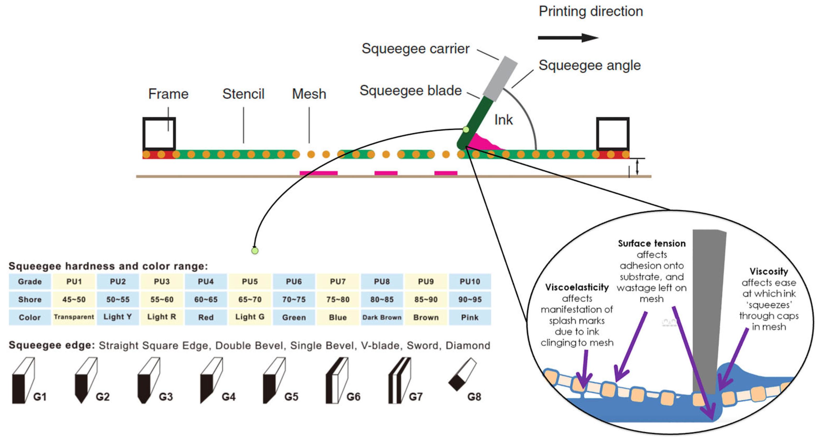
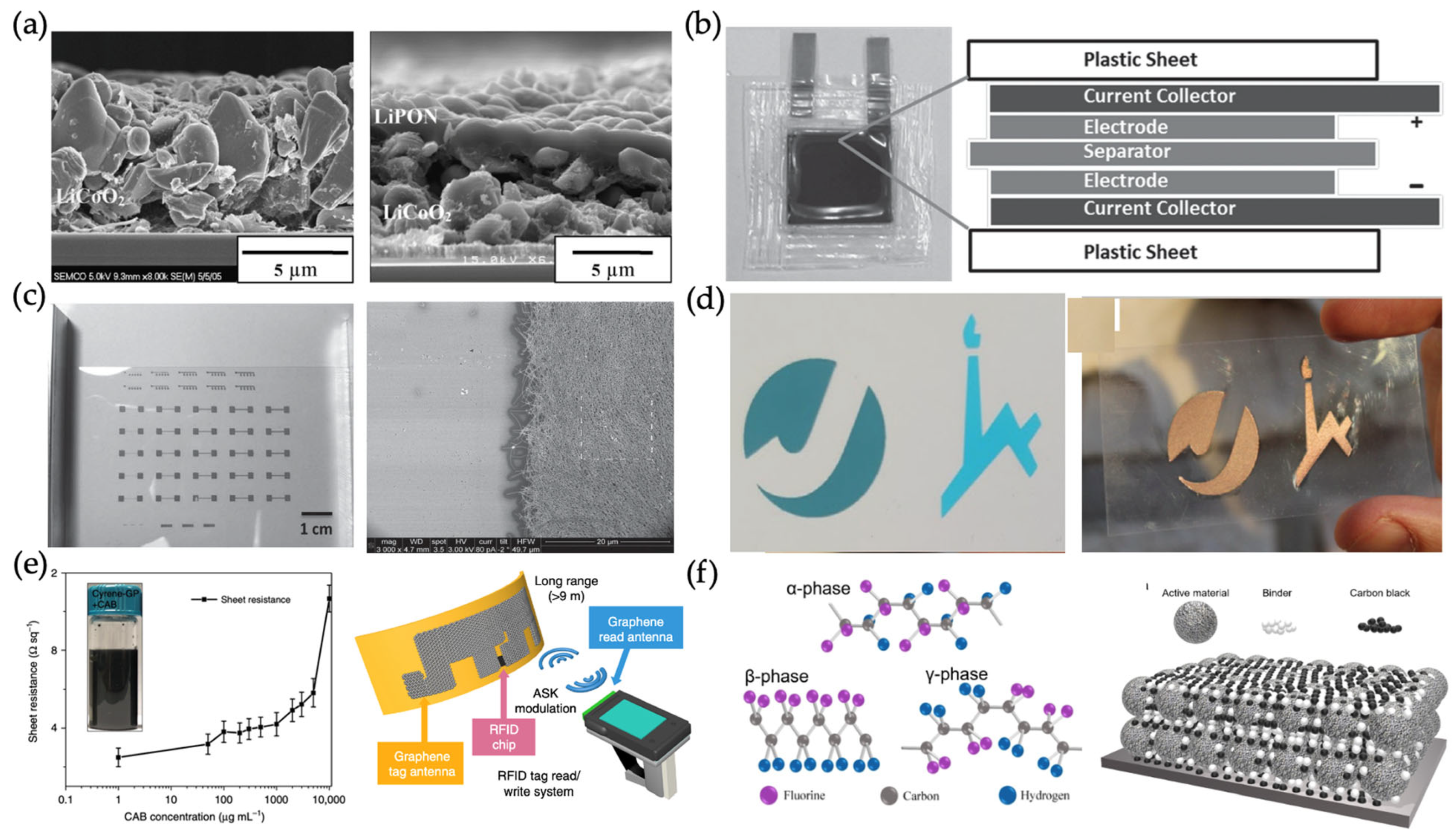

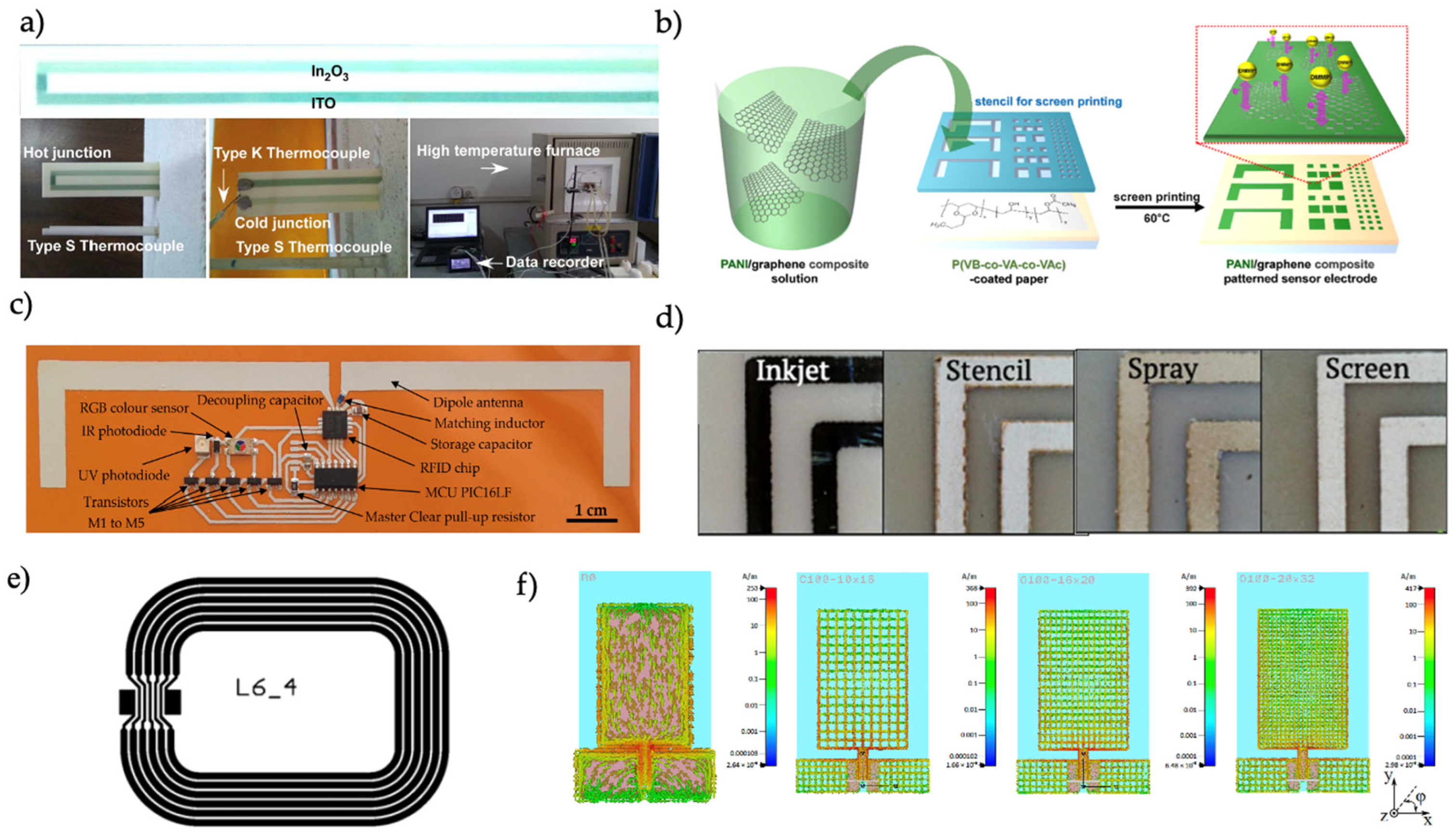
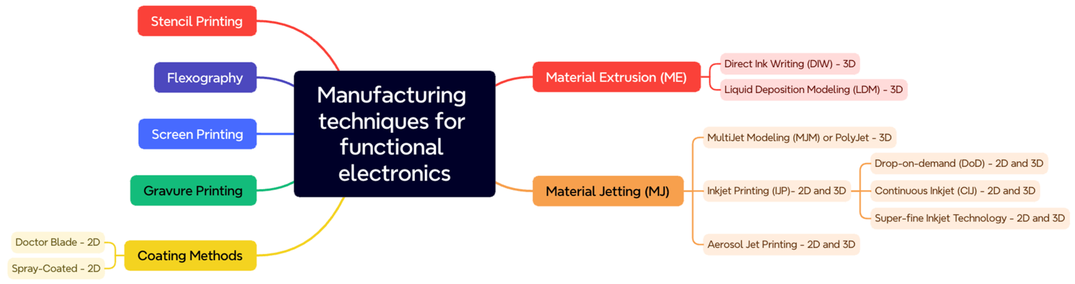

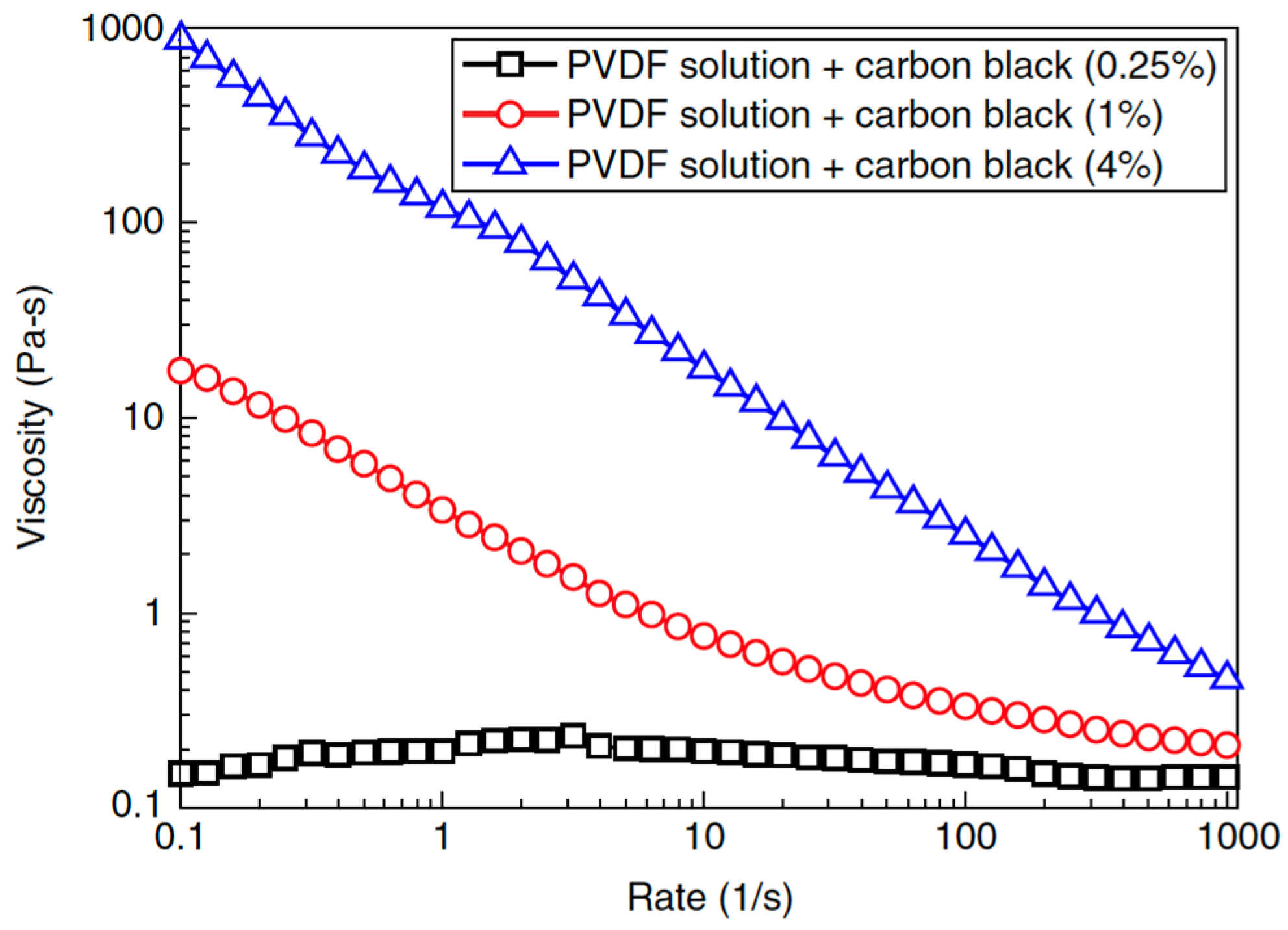
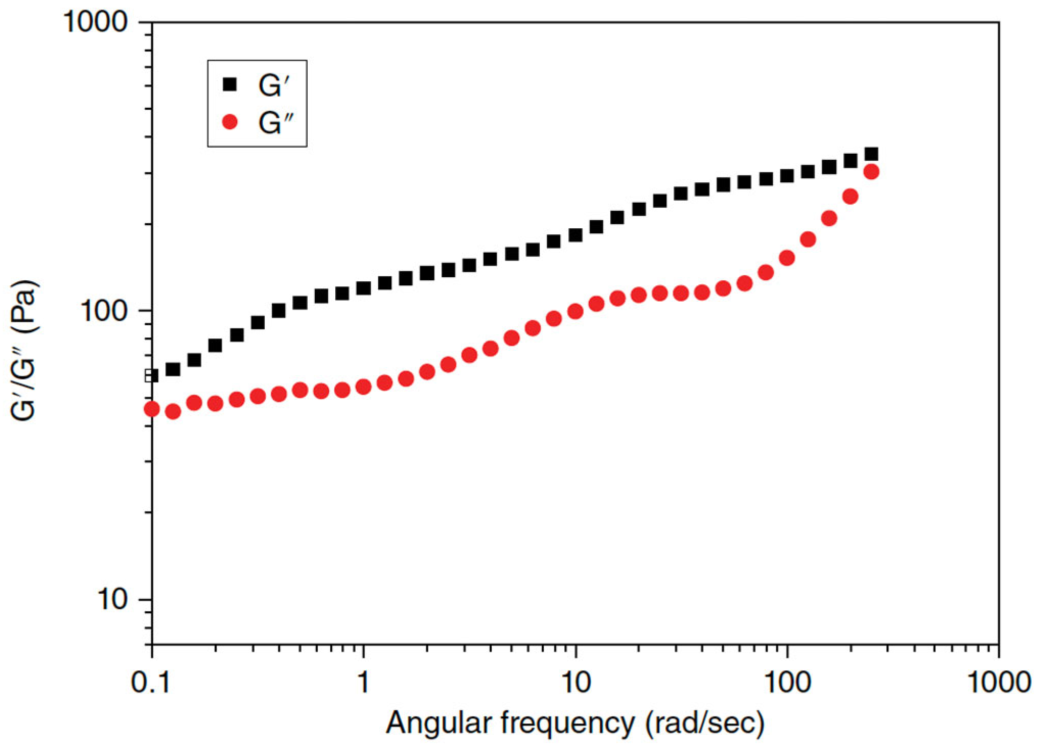
