Article

Implication of Surface Passivation on the In-Plane Charge Transport in the Oriented Thin Films of P3HT

by
Nisarg Hirens Purabiarao
,
Kumar Vivek Gaurav
,
Shubham Sharma
,
Yoshito Ando
and
Shyam Sudhir Pandey
*
Graduate School of Life Science and Systems Engineering, Kyushu Institute of Technology, Kitakyushu, Fukuoka 808-0196, Japan
*
Author to whom correspondence should be addressed.
Electron. Mater. 2025, 6(2), 6; https://doi.org/10.3390/electronicmat6020006
Submission received: 5 March 2025 / Revised: 22 April 2025 / Accepted: 1 May 2025 / Published: 7 May 2025

Abstract

:
Optimizing charge transport in organic semiconductors is crucial for advancing next-generation optoelectronic devices. The performance of organic field-effect transistors (OFETs) is significantly influenced by the alignment of films in the channel direction and the quality of the dielectric surface, which should be uniform, smooth, and free of charge-trapping defects. Our study reports the enhancement of OFET performance using large-area, uniform, and oriented thin films of regioregular poly[3-hexylthiophene] (RR-P3HT), prepared via the Floating Film Transfer Method (FTM) on octadecyltrichlorosilane (OTS) passivated SiO2 surfaces. SiO2 surfaces inherently possess dangling bonds that act as charge traps, but these can be effectively passivated through optimized surface treatments. OTS treatment has improved the optical anisotropy of thin films and the surface wettability of SiO2. Notably, using octadecene as a solvent during OTS passivation, as opposed to toluene, resulted in a significant enhancement of charge carrier transport. Specifically, passivation with OTS-F (10 mM OTS in octadecene at 100 °C for 48 h) led to a >150 times increase in mobility and a reduction in threshold voltage compared to OTS-A (5 mM OTS in toluene for 12 h at room temperature). Under optimal conditions, these FTM-processed RR-P3HT films achieved the best device performance, with a saturated mobility (μsat) of 0.18 cm2V−1s−1.

1. Introduction

Organic field-effect transistors (OFETs) have garnered significant interest from the scientific community due to their potential applications in cost-effective organic electronics [1,2,3]. These applications include flexible displays [2,4], radio-frequency identification (RFID) tags [5,6], wearable electronics [7,8], sensors [9,10], and electronic paper [11,12], etc. A key material in this field is Poly(3-hexylthiophene) (P3HT), a p-type semiconducting polymer renowned for its simple structure, solution processability, self-assembly, and ease of processing [13]. Despite its promising characteristics, the performance of P3HT-based devices is often limited by factors such as charge trapping at grain boundaries, non-optimal molecular orientation, and heterogeneous film morphology. These issues can lead to reduced charge carrier mobility and increased recombination, impacting overall device performance [2]. The polymer semiconductor–dielectric interface plays a crucial role in the charge transport of OFETs, where the semiconductor film morphology, surface energy, and roughness of the dielectric layer profoundly influence charge carrier accumulation, molecular ordering of the semiconductor, and the formation of trap states, ultimately controlling the electrical characteristics and operational stability of devices [14,15]. Surface passivation of the oxide-based gate insulators by forming a self-assembled monolayer (SAM) for OFETs has been widely used for promoting the adhesion and uniformity of the organic semiconductors, along with increasing the grain size, leading to improved carrier mobility. To accomplish this, a SAM of several surface passivating agents like hexamethyldisilazane (HMDS), octadecyltrichlosilane (OTS), 7-octenyl trichlorosilane, benzyltrichlosilane alkene-phosphonic acid, and cinnamic acid, etc., has been used to enhance the charge transport in OFETs [16,17,18,19].
Surface passivation at the semiconductor–dielectric interface is a critical strategy for enhancing charge transport in OFETs, where carefully selected self-assembled monolayers (SAMs) or ultrathin buffer layers minimize trap states, reduce energetic disorder, and promote favorable semiconductor morphology, thereby improving the carrier mobility (μ), threshold voltage (Vth) stability, and overall device performance. This approach of surface passivation using polymeric CYTOP, OTS, and HMDS has also been employed in the recent past by our research group [20].
OTS excels as a surface passivation agent due to its unique molecular structure and interaction with the dielectric surface. The long alkyl chains of OTS form a well-ordered, densely packed monolayer on the SiO2 surface, creating a uniform hydrophobic interface. This self-assembled monolayer effectively reduces the surface energy of the dielectric layer, minimizing the interaction between the semiconductor and any polar groups on the oxide surface. The passivation effect of OTS is further enhanced by its ability to neutralize silanol groups (Si-OH) on the SiO2 surface, which are known to act as charge traps. By forming strong Si-O-Si bonds with the substrate, OTS creates a robust and stable interfacial layer that withstands subsequent processing steps. Moreover, the smooth, low-energy surface provided by the OTS monolayer promotes the growth of larger, more ordered domains of the overlying organic semiconductor, facilitating more efficient charge transport parallel to the interface. Octadecyltrimethoxysilane, octyltrichlorosilane, and octadecyltrichlorosilane have also been reported to improve the μ [21,22,23,24]. The efficacy of OTS in surface passivation is further enhanced by its longer alkyl chains, as these extended molecular structures provide superior surface coverage and create a more effective insulating layer between the dielectric and the semiconductor, resulting in reduced charge trapping and the improved molecular ordering of the overlying organic semiconductor film. OTS treatment significantly enhances in-plane charge transport in OFETs by promoting an edge-on orientation of the semiconductor molecules. This preferred molecular arrangement facilitates efficient charge hopping along the channel [25]. The hydrophobic surface created by OTS encourages the organic semiconductor to adopt this edge-on configuration, leading to the formation of well-ordered domains with improved π-orbital overlap between adjacent molecules. Consequently, OTS-treated devices exhibit improved overall device performance, as the edge-on orientation maximizes the conduction pathway in the critical interfacial layer where charge accumulation occurs.
In recent past, there has been growing interest in oriented thin films for facile, anisotropic in-plane charge transport. The orientation of crystallites or molecules within the thin films plays a pivotal role in determining the charge transport properties, which are critical for the performance of electronic and optoelectronic devices. In anisotropic films, where structural alignment is directed, such as edge-on or face-on orientations, charge mobility is significantly enhanced due to the formation of efficient charge transport pathways. This makes anisotropic films particularly advantageous for applications in OFETs. Conversely, isotropic films, characterized by randomly oriented structures, exhibit uniform properties, but often suffer from reduced charge transport efficiency due to the absence of preferred conductive pathways. Thus, precise control over film orientation is imperative for optimizing charge transport and achieving superior device performance [26]. The Floating Film Transfer (FTM) method, reported by our research group [25] is a technique used to fabricate oriented thin films by transferring a preformed film from a liquid substrate onto a solid substrate. In this method, ink from the desired material to be deposited is dropped at the interface of PTFE slider and liquid substrate, and spread on the suitable orthogonal liquid, forming a thin film as the solvent evaporates. Once the film is formed, the substrate is carefully brought into contact with the liquid surface, and the film is transferred onto it by lifting the substrate, allowing the film to adhere to the surface as it is removed from the liquid.
The orientation of the thin films produced by FTM can vary depending on several factors, including the material properties, the nature of the liquid surface, and the specific conditions during film formation and transfer. Generally, FTM can lead to well-ordered films with anisotropic properties, where the molecular or crystalline orientation may be influenced by surface tension forces and the interaction between the material and the liquid surface. The resulting orientation often exhibits alignment parallel to the substrate, contributing to improved charge transport properties in the case of semiconducting materials. However, the degree of orientation and ordering can be further controlled by adjusting parameters such as the concentration of the solution, the speed of transfer, and the characteristics of the liquid surface.
In this work, we investigated the effect of OTS treatment on the surface wettability of SiO2 substrates and its impact on FTM processed oriented thin films of RR-P3HT using optical and microstructural characterizations, and thereby its effect on the charge transport properties in OFETs. Techniques such as water contact angle measurements, polarized absorption spectroscopy, X-ray diffraction (XRD), and electrical characterization were conducted to elucidate the effect of surface passivation on surface wettability, molecular orientation, film morphology, and the charge carrier mobility of P3HT thin films, respectively. We comprehensively optimized different OTS conditions (OTS-A to OTS-F) before fabricating the RR-P3HT based FTM films. Superior saturated hole mobility (µsat) of about 0.18 cm2V−1s−1 was achieved for RR-P3HT thin films on SiO2/Si treated with 10 mM OTS in octadecene at 100 °C for 48 h (OTS-F). This comprehensive study highlights the critical role of surface passivation using OTS treatment in enhancing the performance of P3HT-based OFETs and provides insights into optimizing fabrication processes for improved device performance.

2. Experimental Section

2.1. Materials

Procured from Lisicon, Merck, Rahway, NJ, USA, the electronic grade RR P3HT and OTS (molecular structure as shown in Figure 1a,b were utilized as-received along with super-dehydrated solvents toluene and octadecene purchased from Fujifilm Wako, Japan. Ethylene glycol (EG) and Glycerol (GL) were acquired from Fujifilm Wako, Japan. These were then blended in a proportion of 3:1 to form a viscous liquid substrate with a viscosity of 10.22 CentiStokes (cSt). Super-dehydrated chloroform was utilized to prepare the RR-P3HT solution at a concentration of 40 mg/mL.

2.2. Methods

To comprehensively investigate the effect of OTS treatment on the OFET device performance, cleaned SiO2 substrates were immersed in two different organic solvents, namely, toluene and octadecene for the OTS concentration of 5 mM and 10 mM, respectively, for 12, 24, 36 h, and 3, 24, and 48 h, respectively. From now onwards, the abovementioned OTS conditions will be mentioned as follows: 5 mM OTS in toluene for 12 h as OTS-A, 5 mM OTS in toluene for 24 h as OTS-B, 5 mM OTS in toluene for 36 h as OTS-C, 10 mM OTS in octadecene at 100 °C for 3 h as OTS-D, 10 mM OTS in octadecene at 100 °C for 24 h as OTS-E, and 10 mM OTS in octadecene at 100 °C for 48 h as OTS-F.

2.2.1. Thin Film Characterizations

Absorption Spectroscopy: The polarized electronic absorption spectra of the RR-P3HT thin film-coated on a glass substrate were measured using a UV−visible−NIR spectrophotometer (JASCO V-570, Tokyo, Japan). To assess optical anisotropy, a Glan−Thompson prism was positioned between the sample and the incident light source, allowing the angle of rotation to control the polarization direction of the incoming beam. This setup enabled measurements of the polarized electronic absorption spectrum in both parallel (||) and perpendicular (⊥) orientations to the film. Optical anisotropy in the oriented thin films prepared by FTM was further analyzed using the dichroic ratio (DR), as specified in Equation (1):
D R = M a x i m u m   A b s o r p t i o n   λ m a x | | A b s o r p t i o n   λ m a x | | .
  • X-Ray Diffraction (XRD): Structural analysis was performed using out-of-plane XRD and in-plane GIXD on thin films deposited on bare silicon substrates, employing a Rigaku diffractometer equipped with a Cu-Kα source. Standard grazing incidence configurations were used to assess the film’s crystallinity and anisotropy, with measurement settings tailored to align with the directional orientation induced by the FTM process.
  • Water Contact Angle (WCA) Measurement: WCA measurements are employed to analyze the hydrophobicity of OTS-treated substrates. WCA on OTS-treated SiO2 substrates was examined by conducting contact angle measurements employing the Kyowa Interface Science Corporation Ltd. machine (Model DMs-401, Saitama, Japan). Before the measurement, the Si/SiO2 substrates were cleaned ultrasonically with acetone for 10 min and then exposed to UV-O3 treatment for 30 min, followed by the OTS treatment at different conditions. In this procedure, a 2 µL droplet of DI water was deposited onto both untreated and treated substrates, and the resulting contact angle in degrees was measured. This measurement was then utilized to ascertain the characteristics of the OTS-treated substrates.

2.2.2. Electrical Characterizations

The charge transport was examined by fabricating OFETs in the bottom gate top contact (BGTC) device configuration, as shown in Figure 1c. OFETs were fabricated on a heavily p-doped Si substrate with a 300 nm thermally grown SiO2 layer as the dielectric, exhibiting an aerial capacitance (Ci) of 10 nF/cm2. At first, the Si/SiO2 samples were gently wiped with hexane. To remove the organic contaminates and native oxide layers, the samples were placed in the piranha solution comprising H2SO4 and H2O2 (4:1) at 100 °C for 3 h. Thereafter, the samples were cleaned ultrasonically with distilled water, acetone, and boiling IPA for 10 min each. To modify the surface properties and enhance cleaning, the samples underwent UV/O3 treatment for 30 min. Thereafter, the substrates were immersed in OTS solution conditioned as OTS-A to OTS-F as mentioned in Section 2.2, to facilitate the SAM formation on the SiO2 surface. Following the SAM formation, the substrates underwent a 10 min cleaning cycle in an ultrasonic bath with toluene and chloroform: cyclohexane in the case of OTS-A to OTS-C and OTS-D to OTS-F, respectively, followed by annealing at 180 °C for 60 min.
Following our previous publications [20], 12 nm thick-oriented thin films of RR-P3HT were fabricated using the FTM on Si/SiO2 substrates for OFET device fabrication. The orientation dominance of RR-P3HT thin film with reference to the source-drain electrode is depicted in Figure 1d. In this approach, a minute quantity (approximately 10 μL) of the polymer solution (4% w/v) in super dehydrated chloroform was gently dropped at the junction of a PTFE slider and the orthogonal liquid substrate was pre-heated at 55 °C, comprising EG and GL (3:1), as depicted schematically in Figure 1e.
The films were cast onto the OTS-treated Si/SiO2 substrates, followed by annealing at 150 °C for 30 min in an argon glovebox. Subsequently, nickel shadow masks with channel dimensions of 30 μm length (L) and 2 mm width (W) were utilized to pattern the source/drain electrodes through thermal evaporation of silver (under ~10−6 Torr). The shadow mask was positioned to ensure that the alignment direction of the main polymer chain was parallel to the channel length. Output and transfer characteristics of the OFETs were measured using a computer-controlled two-channel source-measure unit (Keithley 2612).

3. Results

3.1. WCA Measurement

The theoretical understanding of contact angles involves the thermodynamic equilibrium among three phases: the liquid droplet, the solid substrate, and the surrounding gas or vapor [27]. On flat surfaces, a contact angle of less than 90° signifies a hydrophilic surface, with angles closer to zero indicating a highly hydrophilic surface. Conversely, if the surface is hydrophobic, the contact angle will be greater than 90° [20]. We utilized contact angle measurements to investigate the impact of OTS treatment on the extent of hydrophobicity of the substrate. As shown in Figure 2, the contact angle on the untreated Si/SiO2 was observed to be 63.1°. On the other hand, the contact angles on OTS treated Si/SiO2 conditioned at OTS-A, OTS-B, and OTS-C were found to be 107°, 109.3°, and 112.9°, respectively, and those on OTS-D, OTS-E, and OTS-F were observed to be 106.4°, 108.6°, and 110.2°, respectively. The OTS treatment significantly increases the contact angle on SiO2 surfaces due to the formation of a hydrophobic self-assembled monolayer. OTS molecules chemically bond to the SiO2 via silane groups, with alkyl chains oriented outwards. This arrangement repels water, increasing hydrophobicity and decreasing surface energy. Longer treatment times allow more complete OTS coverage, thus forming dense alkyl chain packing and further increasing the contact angle. The resulting hydrophobic interface promotes favorable organic semiconductor orientation and crystallinity, which is crucial for enhancing charge transport in OFETs. FTM films deposited on OTS-treated surfaces preferentially adopt an edge-on orientation [28]. This alignment is facilitated by the hydrophobic nature of the OTS monolayer, which interacts favorably with the alkyl side chains of the RR-P3HT. The edge-on orientation positions the thiophene backbones perpendicular to the substrate. This arrangement optimizes charge transport along the transistor channel, as the direction of the highest mobility aligns with the current flow. The strong interface between the edge-on oriented polymeric chains of P3HT and the OTS layer enhances charge injection and reduces interfacial traps, contributing to improved OFET performance [20].
To evaluate the effective surface energy (γseff) of different OTS-treated SiO2 substrates, the Zisman plot method [29] was employed. Considering the surface tension of water (γwater) to be 72.8 mN/m (or dyn/cm) at room temperature, the surface energies of OTS-treated SiO2 substrates were evaluated as follows: 9.1 mN/m (OTS-A), 8.3 mN/m (OTS-B), 8.6 mN/m (OTS-C), 9.4 mN/m (OTS-D), 7.9 mN/m (OTS-E), 7.1 mN/m (OTS-F).

3.2. Electronic Absorption Spectroscopy

Figure 3a–f shows the absorption spectra of P3HT thin films fabricated on SiO2 treated with OTS-A, OTS-B, OTS-C, OTS-D, OTS-E, and OTS-F respectively. The UV–visible absorption spectrum of P3HT thin films offers valuable insights into their crystallinity, electronic structure, and excitonic properties. For instance, in RR-P3HT films deposited via FTM on OTS-treated SiO2 substrates, the polarized absorption spectra exhibit a distinct vibronic progression. This pattern is typical of π–π* transitions seen in the polymer. The main vibronic peaks appear at 604 nm (A0-0), 554 nm (A0-1), and 524 nm (A0-2), representing transitions from the ground vibrational state of the electronic ground state to the zeroth, first, and second vibrational levels of the excited state, respectively.
These A0-n transitions (n = 0, 1, 2) are vibrationally resolved and originate within individual polymer chains, reflecting the largely intrachain nature of the excitations. Ideally, the energy of these transitions follows a linear relationship: E(n) = E(0) + nħω, where ħω is the energy of the vibrational mode. The relative intensities of these peaks are governed by the Franck–Condon principle [30] and depend on the Huang–Rhys factor (HR), where intensities scale with HRn/n!. For example, when HR = 1, the intensity ratio is approximately 1:1:0.5; for HR = 2, the ratio becomes 1:2:2.
In the present spectra, the observed intensity ratios suggest an HR value close to 2. However, the corresponding energy values in electron volts—2.05 eV (604 nm), 2.24 eV (554 nm), and 2.37 eV (524 nm)—do not perfectly align with the expected linear progression. This discrepancy suggests deviations from ideal behavior, likely due to effects such as exciton delocalization and interchain interactions. These phenomena are common in semicrystalline conjugated polymer films, where electronic excitations are not confined to individual monomer units.
The parameter W/EP from Equation (2), which connects the intensity ratio of the 0-0 and 0-1 peaks to the excitonic bandwidth, is based on a simplified model of P3HT morphology. However, the structural features in the current films—such as chain orientation, domain size, and molecular packing—differ from those considered in earlier models. Therefore, the values listed in Table 1 for excitonic bandwidth and related optical properties should be interpreted as qualitative markers of how surface treatment influences molecular organization, rather than as precise quantitative values.
A 0 - 0 A 0 - 1 = 1 0.24 W E P 1 + 0.073 W E P 2 .
Generally, larger grain sizes typically result in increased molecular alignment, a phenomenon influenced by factors such as substrate properties and surface treatments like OTS [31]. Consequently, an increase in grain size is often associated with an increase in the dichroic ratio, indicative of improved molecular alignment and crystalline ordering. Also, as shown in Table 2, A0-0/A0-1 increases from 0.60 in the case of OTS-D to 0.75 in the case of OTS-A, and 0.80 in the case of OTS-F. The increase in A0-0/A0-1 validates the enhanced molecular ordering and crystallinity. This corroboration underscores the significant impact of the morphological features on the optical behavior of the thin film. Conversely, the A0-2/A0-1, which reflects intrachain coupling, ascended as OTS-A, OTS-D, and OTS-F. A reduced A0-2/A0-1 ratio (Table 2) indicates a narrower W, leading to a more disordered and narrowly distributed conjugation length.

3.3. XRD Characterizations

To investigate the implications of different OTS surface passivation conditions on the crystallinity and macromolecular orientation, out-of-plane XRD and in-plane GIXD measurements of RR-P3HT thin film coated on OTS-treated SiO2 substrates were conducted.
In this study, we focused on three discrete OTS treatment conditions: OTS-A, OTS-D, and OTS-F, based on distinctive absorption spectral features, crystallinity, and orientation to gain insight into macromolecular crystallinity of thin films. As shown in Figure 4, a prominent diffraction peak associated with the lamellar stacking of the alkyl side chains was observed up to the third order at the 2θ of 5.5°, 11°, and 16°, corresponding to the (hkl) values of (100), (200), and (300), respectively [32,33]. The results demonstrated that the (100) peak was most prominent in the sample treated under OTS-F condition. This was followed by the (100) peak of the sample treated under OTS-A condition, and then the sample treated under OTS-D condition. Additionally, the full width at half maximum (FWHM) was narrower for the sample treated with OTS-F, indicating that the thin film exhibited greater ordering and crystallinity compared to the other two samples. Scherer’s equation was employed to evaluate the crystallite size (d), where k, λ, β, and θ are the shape factor (0.9), wavelength of X-rays (1.5406 Å), FWHM, and Bragg angle, respectively, as formulated in Equation (3). Table 1 shows the tabulation of the crystallite size (d) along with the charge transport, optical, and surface wettability parameters.
d = k λ β c o s Θ .
The in-plane GIXD analysis of RR-P3HT thin films on OTS-treated SiO2 substrates showed no diffraction peaks associated with the alkyl side chains. Instead, it exhibited a single diffraction peak with an (hkl) value of (010) at 23.3°, indicating that all the crystallites are oriented edge-on [34]. This suggests that the RR-P3HT thin films fabricated via FTM on OTS-treated SiO2 are well-ordered and crystalline, as confirmed by both the in-plane and out-of-plane XRD profiles.
Larger crystallites generally have fewer grain boundaries, which can act as barriers to charge transport. With fewer barriers, carriers can move more freely, resulting in higher μ. Also, smaller crystallites possess a greater number of grain boundaries and defects, which can trap charge carriers and elevate recombination rates, thereby diminishing the efficiency of charge transport [35].

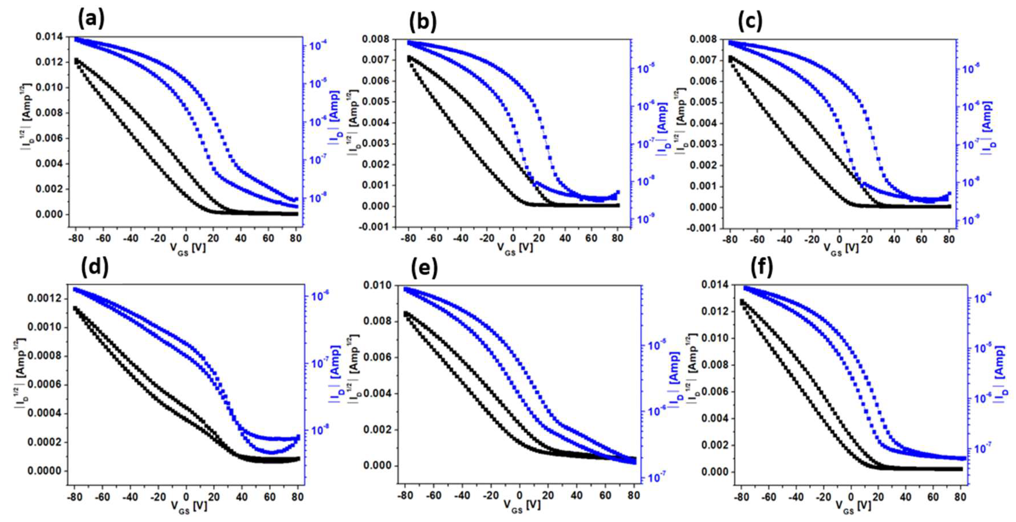
3.4. Electrical Characterizations

The fabrication of OFETs in the BGTC device architecture was conducted to elucidate the effect of OTS treatment on the anisotropic charge transport in the FTM-processed RR-P3HT films. Previous reports from our research group have already indicated that thin film fabrication using FTM resulted in an edge-on orientation, thereby enabling facile in-plane charge transport [25]. Due to the hydrophobic nature of the polymer being studied, Si/SiO2 substrates were treated with OTS to render the surface hydrophobicity of the substrate prior to the thin film fabrication. Equation (4) was employed to calculate the saturated μ (μsat) from the transfer characteristics depicted in Figure 4 within the saturation region. In this context, μsat represents the saturated mobility, while Ci, W, and L denote the areal capacitance, channel width, and channel length, respectively [36,37].
I D S = μ C i W 2 L   ( V G S V t h ) 2
Source-drain current (IDS), gate voltage (VGS), and drain-source voltage (VDS) are the pertinent parameters. μsat was calculated from the slope of the |IDS|1/2 versus VGS plot. The on–off ratio was derived from the comparison of the on-state current to the off-state current in the transfer characteristic [38]. Key device parameters, such as μsat, on–off ratio (Ion/Ioff), and threshold voltage (Vth), derived from the transfer characteristics have been summarized in Table 2.
Surface treatment of bare SiO2 with OTS is a common technique to passivate surface dangling bonds and enhance the molecular packing of organic semiconductors, thus improving device performance [39]. In the case of OFETs fabricated on Si/SiO2 treated with OTS-A, OTS-B, and OTS-C, no significant change in the DR was observed, suggesting similar molecular orientation and crystallinity of the P3HT thin films, and, consequently, there was no observable change in the μsat though there was a slight modification in surface wettability. With an increase in OTS treatment time, the WCA increased in different OTS treatments as mentioned before, which correlates with a decrease in interfacial (dielectric/semiconductor) trap states. This reduction in interfacial trap states resulted in an improvement in the Ion/Ioff and Vth as shown in Figure 5. The output characteristics of the as-fabricated transistors are depicted in Figure 6.
For OFETs fabricated on Si/SiO2 treated with OTS-D, OTS-E, and OTS-F, there was no significant change in the water contact angle, indicating similar interfacial trap states and thus minimal improvement in the Ion/Ioff and Vth. However, there was a noticeable increase in the DR from 1.29 for OTS-D to 1.4 and 1.8 for OTS-E and OTS-F, respectively. This suggests improved molecular ordering and crystallinity of the P3HT thin film, which led to an enhancement in μsat from 10−3 cm2V−1s−1 for OTS-D to 0.18 cm2V−1s−1 for OTS-F.
Beyond the evident enhancement in molecular alignment, another key factor affecting charge transport in RR-P3HT is the presence of trap states. These localized energy states can significantly reduce effective charge carrier mobility and introduce a dependence of mobility on the concentration of charge carriers. When a gate voltage is applied, these trap states gradually become filled, allowing more free carriers to participate in conduction. This phenomenon—commonly known as the trap-filling effect—can lead to a mobility that increases with gate voltage, particularly in systems with higher energetic disorder.
Theoretical and computational studies suggest that in materials with significant energetic disorder, mobility tends to rise with increasing carrier concentration due to trap filling. In contrast, in low-disorder systems, mobility is not only higher but also largely independent of carrier density [40]. Our findings, when compared with Figure 8a of this reference, exhibit a similar trend, highlighting that the extent of energetic disorder—and thereby mobility—is strongly influenced by the specific OTS surface treatment conditions.
This gate-voltage-dependent mobility is particularly visible in the transfer curves (Figure 5). Devices fabricated on OTS-E and OTS-F treated substrates display a consistent and linear increase in μsat with rising gate voltage, indicative of well-passivated surfaces and suppressed trap effects. On the other hand, OTS-D devices deviate from this linearity, a signature of prominent trap-limited transport where mobility becomes sensitive to gate voltage.
These observations are in alignment with previously reported studies. For instance, a study showed that mobility dropped in magnitude and became increasingly dependent on gate voltage due to traps [41]. Similarly, classical models of field-effect mobility [42], and comprehensive reviews [43], also recognize the influence of trap states and energetic disorder on the gate-voltage-dependent behavior of mobility in OFETs.

4. Conclusions

In this study, thin films of RR-P3HT were fabricated using a solution-processable FTM. This approach is effective in fabricating large-area, uniform, and oriented films of RR-P3HT. Surface passivation with OTS is critical for reducing interfacial trap sites, tuning the optical anisotropy of thin films, and controlling film morphology. Optimizing the conditions for SAM formation has been demonstrated to play a dominant role in the surface properties and molecular ordering despite using the same OTS as a surface passivating agent. As compared to toluene, the use of octadecene as a solvent during the surface treatment resulted in improved charge carrier transport. Despite the similar extent of molecular orientation with DR of about 1.8, SiO2 surface passivated using OTS-F condition, led to about 5 times increase in mobility and decrease in the threshold voltage of the OFETs as compared to prepared using OTS-A at room temperature. Even under the same condition of solvent and concentration, just changing surface passivation time from 3 h to 48 h led to an enhancement of >2 orders of magnitude in the charge carrier mobility. Under the optimum condition, utilization of the FTM-processed RR P3HT films on SiO2 conditioned with OTS-F exhibited the best device performance, with a charge carrier mobility (μ) of 0.18 cm2V−1s−1.

Author Contributions

N.H.P.: data curation, formal analysis, visualization, methodology, investigation, writing—original draft preparation; K.V.G.: validation, review, and editing original draft; S.S.: validation, review, and editing original draft; Y.A.: validation, resources; S.S.P.: conceptualization, resources, validation, visualization, supervision, project administration. All authors have read and agreed to the published version of the manuscript.

Funding

This research received no external funding.

Data Availability Statement

Data will be made available on request.

Acknowledgments

N.H. Purabiarao, K.V.G., and S.S. would like to express sincere thanks to the Japanese government’s Ministry of Education, Science, Sports and Culture (MEXT) for providing scholarships for carrying out the present research. N.H. Purabiarao would also like to thank Jacqueline Lease for her support in conducting the contact angle measurement for this study.

Conflicts of Interest

The authors declare no conflicts of interest.

References

  1. Facchetti, A.; Yoon, M.-H.; Marks, T.J. Gate Dielectrics for Organic Field-Effect Transistors: New Opportunities for Organic Electronics. Adv. Mater. 2005, 17, 1705–1725. [Google Scholar] [CrossRef]
  2. Liu, K.; Ouyang, B.; Guo, X.; Guo, Y.; Liu, Y. Advances in Flexible Organic Field-Effect Transistors and Their Applications for Flexible Electronics. npj Flex. Electron. 2022, 6, 1. [Google Scholar] [CrossRef]
  3. Forrest, S.R. The Path to Ubiquitous and Low-Cost Organic Electronic Appliances on Plastic. Nature 2004, 428, 911–918. [Google Scholar] [CrossRef] [PubMed]
  4. Amegadze, P.S.K.; Noh, Y.-Y. Development of High-Performance Printed Polymer Field-Effect Transistors for Flexible Display. J. Inf. Disp. 2014, 15, 213–229. [Google Scholar] [CrossRef]
  5. Baude, P.F.; Ender, D.A.; Haase, M.A.; Kelley, T.W.; Muyres, D.V.; Theiss, S.D. Pentacene-Based Radio-Frequency Identification Circuitry. Appl. Phys. Lett. 2003, 82, 3964–3966. [Google Scholar] [CrossRef]
  6. Subramanian, V.; Chang, P.C.; Lee, J.B.; Molesa, S.E.; Volkman, S.K. Printed Organic Transistors for Ultra-Low-Cost RFID Applications. IEEE Trans. Compon. Packag. Technol. 2005, 28, 742–747. [Google Scholar] [CrossRef]
  7. Xu, X.; Zhao, Y.; Liu, Y. Wearable Electronics Based on Stretchable Organic Semiconductors. Small 2023, 19, 2206309. [Google Scholar] [CrossRef]
  8. Lee, M.Y.; Lee, H.R.; Park, C.H.; Han, S.G.; Oh, J.H. Organic Transistor-Based Chemical Sensors for Wearable Bioelectronics. Acc. Chem. Res. 2018, 51, 2829–2838. [Google Scholar] [CrossRef]
  9. Stassen, I.; Burtch, N.; Talin, A.; Falcaro, P.; Allendorf, M.; Ameloot, R. An Updated Roadmap for the Integration of Metal–Organic Frameworks with Electronic Devices and Chemical Sensors. Chem. Soc. Rev. 2017, 46, 3185–3241. [Google Scholar] [CrossRef]
  10. Roberts, M.E.; Sokolov, A.N.; Bao, Z. Material and Device Considerations for Organic Thin-Film Transistor Sensors. J. Mater. Chem. 2009, 19, 3351. [Google Scholar] [CrossRef]
  11. Eder, F.; Klauk, H.; Halik, M.; Zschieschang, U.; Schmid, G.; Dehm, C. Organic Electronics on Paper. Appl. Phys. Lett. 2004, 84, 2673–2675. [Google Scholar] [CrossRef]
  12. Logothetidis, S. Flexible Organic Electronic Devices: Materials, Process and Applications. Mater. Sci. Eng. B 2008, 152, 96–104. [Google Scholar] [CrossRef]
  13. Cheng, S.; Wang, Y.; Zhang, R.; Wang, H.; Sun, C.; Wang, T. Recent Progress in Gas Sensors Based on P3HT Polymer Field-Effect Transistors. Sensors 2023, 23, 8309. [Google Scholar] [CrossRef]
  14. Luo, L.; Liu, Z. Recent Progress in Organic Field-effect Transistor-based Chem/Bio-sensors. View 2022, 3, 20200115. [Google Scholar] [CrossRef]
  15. Dinelli, F.; Murgia, M.; Levy, P.; Cavallini, M.; Biscarini, F.; de Leeuw, D.M. Spatially Correlated Charge Transport in Organic Thin Film Transistors. Phys. Rev. Lett. 2004, 92, 116802. [Google Scholar] [CrossRef]
  16. Swiggers, M.L.; Xia, G.; Slinker, J.D.; Gorodetsky, A.A.; Malliaras, G.G.; Headrick, R.L.; Weslowski, B.T.; Shashidhar, R.N.; Dulcey, C.S. Orientation of Pentacene Films Using Surface Alignment Layers and Its Influence on Thin-Film Transistor Characteristics. Appl. Phys. Lett. 2001, 79, 1300–1302. [Google Scholar] [CrossRef]
  17. Kelley, T.W.; Boardman, L.D.; Dunbar, T.D.; Muyres, D.V.; Pellerite, M.J.; Smith, T.P. High-Performance OTFTs Using Surface-Modified Alumina Dielectrics. J. Phys. Chem. B 2003, 107, 5877–5881. [Google Scholar] [CrossRef]
  18. Salleo, A.; Chabinyc, M.L.; Yang, M.S.; Street, R.A. Polymer Thin-Film Transistors with Chemically Modified Dielectric Interfaces. Appl. Phys. Lett. 2002, 81, 4383–4385. [Google Scholar] [CrossRef]
  19. Herzer, N.; Hoeppener, S.; Schubert, U.S. Fabrication of Patterned Silane Based Self-Assembled Monolayers by Photolithography and Surface Reactions on Silicon-Oxide Substrates. Chem. Commun. 2010, 46, 5634. [Google Scholar] [CrossRef]
  20. Gaurav, K.V.; Rai, H.; Singh, K.R.; Sharma, S.; Ando, Y.; Pandey, S.S. Clarifying the Dominant Role of Crystallinity and Molecular Orientation in Differently Processed Thin Films of Regioregular Poly(3-Hexylthiophene). Micromachines 2024, 15, 677. [Google Scholar] [CrossRef]
  21. Kobayashi, S.; Nishikawa, T.; Takenobu, T.; Mori, S.; Shimoda, T.; Mitani, T.; Shimotani, H.; Yoshimoto, N.; Ogawa, S.; Iwasa, Y. Control of Carrier Density by Self-Assembled Monolayers in Organic Field-Effect Transistors. Nat. Mater. 2004, 3, 317–322. [Google Scholar] [CrossRef] [PubMed]
  22. Lin, Y.-Y.; Gundlach, D.J.; Nelson, S.F.; Jackson, T.N. Stacked Pentacene Layer Organic Thin-Film Transistors with Improved Characteristics. IEEE Electron. Device Lett. 1997, 18, 606–608. [Google Scholar] [CrossRef]
  23. Tang, M.L.; Okamoto, T.; Bao, Z. High-Performance Organic Semiconductors: Asymmetric Linear Acenes Containing Sulphur. J. Am. Chem. Soc. 2006, 128, 16002–16003. [Google Scholar] [CrossRef] [PubMed]
  24. Ong, B.S.; Wu, Y.; Liu, P.; Gardner, S. High-Performance Semiconducting Polythiophenes for Organic Thin-Film Transistors. J. Am. Chem. Soc. 2004, 126, 3378–3379. [Google Scholar] [CrossRef]
  25. Sharma, S.; Vats, A.K.; Pandey, M.; Nagamatsu, S.; Chen, J.-C.; Pandey, S.S. Unraveling the Implications of Macromolecular Orientation on the Planar and Vertical Charge Transport in Organic Electronic Devices. ACS Appl. Polym. Mater. 2022, 4, 8315–8323. [Google Scholar] [CrossRef]
  26. Sharma, S.; Vats, A.K.; Tang, L.; Kaishan, F.; Toyoda, J.; Nagamatsu, S.; Ando, Y.; Tamagawa, M.; Tanaka, H.; Pandey, M.; et al. High Field-Effect Mobility in Oriented Thin Films of D-A Type Semiconducting Polymers by Engineering Stable Interfacial System. Chem. Eng. J. 2023, 469, 143932. [Google Scholar] [CrossRef]
  27. Li, H.; Li, N.; Zhang, Y.; He, H.; Liu, Z. Anti-Reflection OTS-Treated SiO2 Thin Films with Super-Hydrophobic Property. J. Sol-Gel Sci. Technol. 2017, 83, 518–526. [Google Scholar] [CrossRef]
  28. Hayakawa, R.; Petit, M.; Chikyow, T.; Wakayama, Y. Interface Engineering for Molecular Alignment and Device Performance of Quaterrylene Thin Films. Appl. Phys. Lett. 2008, 93, 153301. [Google Scholar] [CrossRef]
  29. Kabza, K.G.; Gestwicki, J.E.; McGrath, J.L. Contact Angle Goniometry as a Tool for Surface Tension Measurements of Solids, Using Zisman Plot Method. A Physical Chemistry Experiment. J. Chem. Educ. 2000, 77, 63. [Google Scholar] [CrossRef]
  30. Lax, M. The Franck-Condon Principle and Its Application to Crystals. J. Chem. Phys. 1952, 20, 1752–1760. [Google Scholar] [CrossRef]
  31. Headrick, R.L.; Wo, S.; Sansoz, F.; Anthony, J.E. Anisotropic Mobility in Large Grain Size Solution Processed Organic Semiconductor Thin Films. Appl. Phys. Lett. 2008, 92, 063302. [Google Scholar] [CrossRef]
  32. Goh, R.G.S.; Waclawik, E.R.; Motta, N.; Bell, J.M. Influence of Dispersed Carbon Nanotubes on the Optical and Structural Properties of a Conjugated Polymer; Chiao, J.-C., Dzurak, A.S., Jagadish, C., Thiel, D.V., Eds.; SPIE: Bellingham, WA, USA, 2005; p. 60370Z. [Google Scholar]
  33. Sugiyama, K.; Kojima, T.; Fukuda, H.; Yashiro, H.; Matsuura, T.; Shimoyama, Y. ESR and X-Ray Diffraction Studies on Thin Films of Poly-3-Hexylthiophene: Molecular Orientation and Magnetic Interactions. Thin Solid. Film. 2008, 516, 2691–2694. [Google Scholar] [CrossRef]
  34. Pandey, M.; Kumari, N.; Nagamatsu, S.; Pandey, S.S. Recent Advances in the Orientation of Conjugated Polymers for Organic Field-Effect Transistors. J. Mater. Chem. C Mater. 2019, 7, 13323–13351. [Google Scholar] [CrossRef]
  35. Virkar, A.; Mannsfeld, S.; Oh, J.H.; Toney, M.F.; Tan, Y.H.; Liu, G.; Scott, J.C.; Miller, R.; Bao, Z. The Role of OTS Density on Pentacene and C 60 Nucleation, Thin Film Growth, and Transistor Performance. Adv. Funct. Mater. 2009, 19, 1962–1970. [Google Scholar] [CrossRef]
  36. Sirringhaus, H. 25th Anniversary Article: Organic Field-Effect Transistors: The Path Beyond Amorphous Silicon. Adv. Mater. 2014, 26, 1319–1335. [Google Scholar] [CrossRef]
  37. Sharma, S.; Nagamatsu, S.; Singh, V.; Pandey, S.S. Facile Fabrication and Characterization of Oriented and Multilayer Thin Films of Solution Processable Conjugated Polymer. Phys. Status Solidi (a) 2023, 220, 2300194. [Google Scholar] [CrossRef]
  38. Rai, H.; Vivek Gaurav, K.; Pradhan, S.; Desu, M.; Sharma, S.; Nagamatsu, S.; Pandey, S.S. Vertical Distribution of Molecular Orientation and Its Implication on Charge Transport in Floating Films of Conjugated Polymers. Phys. Status Solidi (a) 2023, 220, 2300236. [Google Scholar] [CrossRef]
  39. Xie, Y.; Cai, S.; Shi, Q.; Ouyang, S.; Lee, W.-Y.; Bao, Z.; Matthews, J.R.; Bellman, R.A.; He, M.; Fong, H.H. High Performance Organic Thin Film Transistors Using Chemically Modified Bottom Contacts and Dielectric Surfaces. Org. Electron. 2014, 15, 2073–2078. [Google Scholar] [CrossRef]
  40. Toman, P.; Menšík, M.; Bartkowiak, W.; Pfleger, J. Modelling of the Charge Carrier Mobility in Disordered Linear Polymer Materials. Phys. Chem. Chem. Phys. 2017, 19, 7760–7771. [Google Scholar] [CrossRef]
  41. Menšík, M.; Toman, P.; Bielecka, U.; Bartkowiak, W.; Pfleger, J.; Paruzel, B. On the Methodology of the Determination of Charge Concentration Dependent Mobility from Organic Field-Effect Transistor Characteristics. Phys. Chem. Chem. Phys. 2018, 20, 2308–2319. [Google Scholar] [CrossRef]
  42. Horowitz, G.; Hajlaoui, M.E.; Hajlaoui, R. Temperature and Gate Voltage Dependence of Hole Mobility in Polycrystalline Oligothiophene Thin Film Transistors. J. Appl. Phys. 2000, 87, 4456–4463. [Google Scholar] [CrossRef]
  43. Baranovskii, S.D. Theoretical Description of Charge Transport in Disordered Organic Semiconductors. Phys. Status Solidi (b) 2014, 251, 487–525. [Google Scholar] [CrossRef]
Figure 1. (a) Molecular structure of (a) RR-P3HT, (b) OTS-18, (c) OFET device architecture, (d) orientation dominance of RR-P3HT, and (e) Schematic diagram of FTM.
Electronicmat 06 00006 g001
Figure 2. WCA on (a) untreated SiO2, (b) OTS-A, (c) OTS-B, (d) OTS-C, (e) OTS-D, (f) OTS-E, and (g) OTS-F.
Electronicmat 06 00006 g002
Figure 3. Polarized absorption spectra consisting of parallel (solid line) and perpendicular (dotted line) of P3HT thin film on (a) OTS-A, (b) OTS-B, (c) OTS-C, (d) OTS-D, (e) OTS-E, and (f) OTS-F.
Electronicmat 06 00006 g003
Figure 4. (a) Out-of-plane XRD, and in-plane GIXD for (b) OTS-A, (c) OTS-D, and (d) OTS-F.
Electronicmat 06 00006 g004
Figure 5. Transfer characteristics Id vs VGs (blue) and root Id vs VGS (black) of RR−P3HT OFETs fabricated with (a) OTS−A, (b) OTS−B, (c) OTS−C, (d) OTS−D, (e) OTS−E, and (f) OTS−F.
Electronicmat 06 00006 g005
Figure 6. Output characteristics of RR−P3HT OFETs fabricated with (a) OTS−A, (b) OTS−B, (c) OTS−C, (d) OTS−D, (e) OTS−E, and (f) OTS−F.
Electronicmat 06 00006 g006
Table 1. Effect of OTS treatment on the optical anisotropy of the UFTM processed films.
OTSDRd (nm)WCA (°)A0-0A0-1A0-2A0-0/A0-1A0-1/A0-2W (meV)
OTS-A1.8522.661070.040.060.060.751.0079.5
OTS-D1.2919.53106.40.110.180.170.601.06137
OTS-F1.8022.93110.20.050.060.050.801.0862.2
Table 2. Electrical parameters of RR-P3HT OFETs fabricated on OTS-treated SiO2 substrates.
Surface ModificationsTreatment Time
(h)
Temperature
(°C)
μsat
(cm2V−1s−1)
Ion/IoffVth
(V)
OTS-A12254 × 10−210520
OTS-B24253 × 10−210412
OTS-C36253 × 10−210410.5
OTS-D310010−310215
OTS-E241000.125 × 1027.3
OTS-F481000.183.2 × 1034
Disclaimer/Publisher’s Note: The statements, opinions and data contained in all publications are solely those of the individual author(s) and contributor(s) and not of MDPI and/or the editor(s). MDPI and/or the editor(s) disclaim responsibility for any injury to people or property resulting from any ideas, methods, instructions or products referred to in the content.

