Article

C60/CZTS Junction Combination to Improve the Efficiency of CZTS-Based Heterostructure Solar Cells: A Numerical Approach

1
Department of Physical Science and Engineering, Nagoya Institute of Technology, Nagoya 466-8555, Japan
2
Department of Electrical and Electronic Engineering, International Islamic University Chittagong, Chittagong 4318, Bangladesh
*
Author to whom correspondence should be addressed.
Electron. Mater. 2024, 5(3), 145-159; https://doi.org/10.3390/electronicmat5030010
Submission received: 7 June 2024 / Revised: 10 August 2024 / Accepted: 14 August 2024 / Published: 15 August 2024

Abstract

:
This work presents a copper zinc tin sulfide (CZTS)-based solar cell structure (AI/ITO/C60/CZTS/SnS/Pt) with C60 as a buffer layer, developed using the SCAPS-1D simulator by optimizing each parameter to calculate the output. Optimizing the parameters, the acceptor concentration and thickness were altered from 6.0 × 1015 cm−3 to 6.0 × 1018 cm−3 and 1500 nm to 3000 nm, respectively. Although, in this simulator, we can tune the value for the acceptor concentration to 6.0 × 10²², higher doping might present an issue regarding adjustment in the physical experiment. Thus, tunable parameters need to be chosen according to the reliability of the experimental work. The defect density varied from 1.0 × 1014 cm−3 to 1.0 × 1017 cm−3 and the auger hole/electron capture coefficient was determined to be 1.0 × 10⁻²⁶ cm6 s−1 for the maintenance of the minorities in theoretical to quasi-proper experimental measurements. Although the temperature was intended to be kept near room temperature, this parameter was varied from 290 K to 475 K to investigate the effects of the temperature on this cell. The optimization of the proposed structure resulted in a final acceptor concentration of 6.0 × 1018 cm−3 and a thickness of 3000 nm at a defect density of 1.0 × 1015 cm−3, which will help to satisfy the desired experimental performance. Satisfactory outcomes (VOC = 1.24 V, JSC = 27.03 mA/cm2, FF = 89.96%, η = 30.18%) were found compared to the previous analysis.

1. Introduction

Today’s world is experiencing problems for several reasons; among them are the burning of fossil fuels and the excessive energy demand. Fossil fuel combustion creates pollution by generating gases such as CO2, NO2, CO, SO2, etc. [1]. Low-cost renewable energy can be used to address the environmental pollution caused by burning fossil fuels [2,3]. Photovoltaic (PV) solar cells that capture photons from the sun are a promising alternative to fossil fuels due to their significantly lower lifecycle greenhouse gas [4,5] emissions and their potential to replace fossil fuels completely. For example, covering only 0.16% of the Earth’s land surface with 10% efficiency PV solar cells can satisfy the global energy demand [6]. Furthermore, solar energy contributes to energy independence, job creation, and economic growth, while also improving public health and quality of life.
A solar cell or photovoltaic (PV) cell is a device composed of semiconductor materials such as silicon, gallium arsenide, and cadmium telluride, among others, that converts sunlight directly into electricity [7,8]. More than 80% of the current photovoltaic (PV) industry is based on c-Si and p-Si wafer technologies [9,10]. When solar cells absorb sunlight, they generate free electrons and holes at positive and negative junctions. If the positive and negative junctions of the solar cells [11] are connected to direct current (DC) electrical equipment, the current is delivered to operate the electrical equipment. A thin-film (TF) solar cell is a second-generation solar cell that is developed by coating one or more thin layers of photovoltaic material onto a substrate such as glass, plastic, or metal. Researchers are trying to introduce thin-film photovoltaic devices, an area that has greatly increased in the last decade [12]. Several materials (such as CdTe, CIS, and CIGS) have been employed by researchers to obtain low-cost and high-efficiency solar cells [13].
Thin-film PV technologies are based on direct-bandgap materials like copper indium (gallium) diselenide (CIGS), copper indium diselenide (CIS), and cadmium telluride (CdTe) and have reached the commercialization stage, with the highest reported conversion efficiency of 11% in module production [14,15,16]. Single-junction thin-film solar cells, which have achieved high efficiency and show excellent performance, utilize GaAs [17], CdTe, or Cu(In,Ga)Se2 (CIGS) [18] as the absorber. Due to the toxicity of Cd and Se and availability issues for In and Te, the production of PV devices based on this absorber layer is limited [19]. In the case of GaAs and CdTe, the toxicity concerns associated with the use of arsenic and cadmium, respectively, may limit their widespread application [20,21]. For CIGS, the use of indium reduces its potential to reach the terawatt scale due to the limited number of economic reserves and the high material costs resulting from the large demand from the display industry [22]. Quaternary semiconductors with a kestrite mineral structure are promising candidates to satisfy the requirements of low-cost and eco-friendly thin-film solar cells [23]. Copper zinc tin sulfide (CZTS) has attracted the attention of many researchers as it is a promising compound in the sense that it fulfills two essential conditions. Indeed, it is composed of eco-friendly and low-cost elements [24]. A recent research paper explored the use of a non-toxic Zn (O, S) buffer layer in CZTS solar cells as an alternative to CdS, highlighting its tunable optical bandgap and potential for improved efficiency. However, the challenges in accurately modeling defects and traps in the layers/interfaces and the need for further optimization of the Zn (O, S)/CZTS solar cell structure for enhanced performance represent obstacles [25]. Another finding was highlighted by Siham et al., demonstrating the exceptional performance of MoOx and CuI as HTLs, surpassing SnS by a significant margin. Specifically, MoOx and CuI demonstrate remarkable power conversion efficiency of 23.73% [26]. The incorporation of SnS as an ETL with CZTS has been demonstrated in a previous study where the utilization of SnS2 as the ETL material in conjunction with CZTS as the absorber layer material yielded the maximum efficiency of 21.89%, an open-circuit voltage (VOC) of 0.97 V, a short-circuit current density (JSC) of 26.53 mA/cm2, and a fill factor (FF) of 84.86% [27]. Another study focused on enhancing a Cu2ZnSnS4 (CZTS)-based solar cell’s performance by incorporating ultrathin Zr and W interlayers at the SnO2:F/CZTS interface, aiming to improve the ohmic properties of the back contacts and the overall cell efficiency [28].
The copper zinc tin sulfide (CZTS) mineral is found in nature [29]. The copper zinc tin chalcogenide is a quaternary semiconductor of group I-II-IV-VI that was first elaborated in 1966, and, afterward, its photovoltaic effect was confirmed in 1988 [24,30]. There has been extensive investigation into the use of other materials to replace the harmful CdS buffer layer in CZTS-based solar cells [31]. CZTS is classified into two crystallographic types: stannite and kieserite. The two structures are similar except for the placement of the Cu and Zn atoms. However, the CZTS material frequently arises in the kieserite phase because it is thermodynamically more stable than stannite. The scientific community has become more interested in non-toxic, low-cost, and readily available absorber materials. CZTS-based materials are p-type semiconductors with a hole density of around 1016 cm–3, which is characteristic of CIGS in high-efficiency CIGS solar cells [32]. Thus, it can be stated that a Cu2ZnSnS4 (CZTS) quaternary semiconductor is a good choice for solar absorber materials. The components of CZTS are abundant in the Earth’s crust (Cu: 50 ppm, Zn: 75 ppm, Sn: 2.2 ppm, S: 260 ppm) and have exceedingly low toxicity. Moreover, other properties of CZTS, such as the high absorption coefficient of over 104 cm–1 and the direct bandgap value of about 1.4–1.5 eV, make these solar cells attractive candidates [33]. The highest laboratory-level CZTS solar cell efficiency is 8.4% [34], while the theoretical conversion efficiency of 18.05% for CZTS/CdS solar cells was reported in 2017 [35]. CZTS-based materials are highly suitable for use as absorbers. Firstly, they possess a Shockley–Queisser limit (SQL) of at least 30.9% (for a bandgap of 1.0 eV) [36]. This minimum is close to the SQL maximum of 33.7% for a single-junction solar cell with a bandgap of 1.34 eV [37,38].
Fullerene-C60, also known as Buckminsterfullerene, stands out for its unique structure, which simulates a hollow ball formed of carbon atoms; C60 has been utilized as a hole blocking layer (HBL) and an electron injection layer (EIL) to enhance the performance [39]. It is adept in transporting electrons and is compatible with the materials used in solar panels. Electron transport layers (ETL) promote charge extraction, minimize recombination losses, and increase the overall device efficiency. The efficient movement of electrons from the CZTS layer to the electrode reduces energy waste and improves the total solar panel performance. In some previous studies, researchers have introduced SnS as a potential BSF to achieve high power conversion efficiency in solar cells [40,41,42]. Surface recombination at the back contact is a significant obstacle in these devices. To address this issue, this work introduces back-surface field (BSF) layers to minimize back-surface recombination. Tin sulfide (SnS) is employed as the BSF material in this context.
In this work, a heterostructure is proposed via the junction (n/p) created with fullerene (C60) and CZTS. The aim is to use this CZTS-based heterostructure with fullerene to improve cell efficiency, along with the other outputs. In this structure, optimization is implemented, showing comparatively better outcomes than the previous CZTS-based heterostructure model [43]. This theoretical study is conducted using a computer-based numerical simulation. The literature and comparative studies are discussed with regard to similar previous works for a better understanding of the improvements in this relevant field. In a physical experiment, a structure with the same parameters might show poorer outcomes than in a simulation regarding actual defects and focusing on materials with individual minorities. A clear difference can be seen through the comparison of similar works.

2. Device Modeling and Simulation Parameters

The suggested structure, Al/ITO/C60/CZTS/SnS/Pt, was analyzed numerically using the SCAPS-1D simulator. SCAPS-1D is a one-dimensional simulator that uses steady-state solutions to three essential equations for semiconductor devices: Poisson’s equation, the continuity equation for free holes, and the continuity equation for free electrons [44,45]. To utilize this computer-based simulator, the electrical and optical properties of each designated layer are used as simulation input parameters. It enables the simulation of the physical and electrical structures of heterojunctions, homojunctions, multifunction’s, and even Schottky barriers. This simulator can regulate each layer’s specific input settings.
The Poisson equation:
d i v ( ε Ψ ) = ρ
The continuity equation for free electrons:
n t = 1 q d i v j n + G n R n
The continuity equation for free holes:
p t = 1 q d i v j p + G p R p
where ε = Dielectric permittivity; Ψ = Electrostatic potential field; n, p = Electron and hole concentrations; Gn, Gp = Generation rate of electrons and holes; Rn, Rp = Recombination rate of electrons and holes; jn, jp = Current densities of electrons and holes.
Figure 1 shows the planar device structure of the designated final solar cell. The substrate-type device structure is used here, and the construction of the device’s structure is mostly affected by the technological feasibility and success in CZTS-based solar cell applications.
Table 1 shows the input parameters of each layer used to create the proposed heterostructure. Here, two parameters (the thickness and acceptor concentration) of the absorber, CZTS, are tuned from 1500 nm to 3000 nm and 6.0 × 1015 cm−3 to 6.0 × 1018 cm−3, respectively.
Table 2 describes the characteristics of the front and back contacts employed in this study. The value of the surface recombination velocity is utilized alternately for electrons and holes, as described in prior published work [46,48,49,50]. Individual contact has been assigned a work function.
Table 3 displays the interface defect parameters for three interfaces constructed using (i) n-type/n-type, (ii) n-type/p-type, and (iii) p-type/p-type structures, with a Gaussian energy distribution utilized in the junction (n/p) established in this structure.
Table 4 shows the defect parameters for specific semiconductor layers, which are calculated as a combination of minority and crystal defects. The defects range from 1.0 × 10¹⁴ to 1.0 × 1017 cm−3 for a reasonable conclusion with a comparably superior outcome. We use a single energetic distribution and the capture cross-sections of electrons and holes are kept at 1.0 × 10⁻¹⁵ cm2 for each semiconductor layer. The Auger hole/electron capture coefficient, which has been set at 1.0 × 10⁻²⁶ cm6 s−1, is crucial in maintaining the minority carrier concentrations in theoretical models. This value ensures consistency when comparing theoretical predictions to quasi-experimental measurements, thereby enhancing the reliability and accuracy of the experimental validation. To physically replicate a heterostructure cell, a composite composed of appropriate semiconductors is necessary. Semiconductors frequently require minority and crystal defects to create a junction.

3. Simulation Results and Discussion

  • Structure—Al/ITO/C60/CZTS/SnS/Pt

3.1. Band Diagram

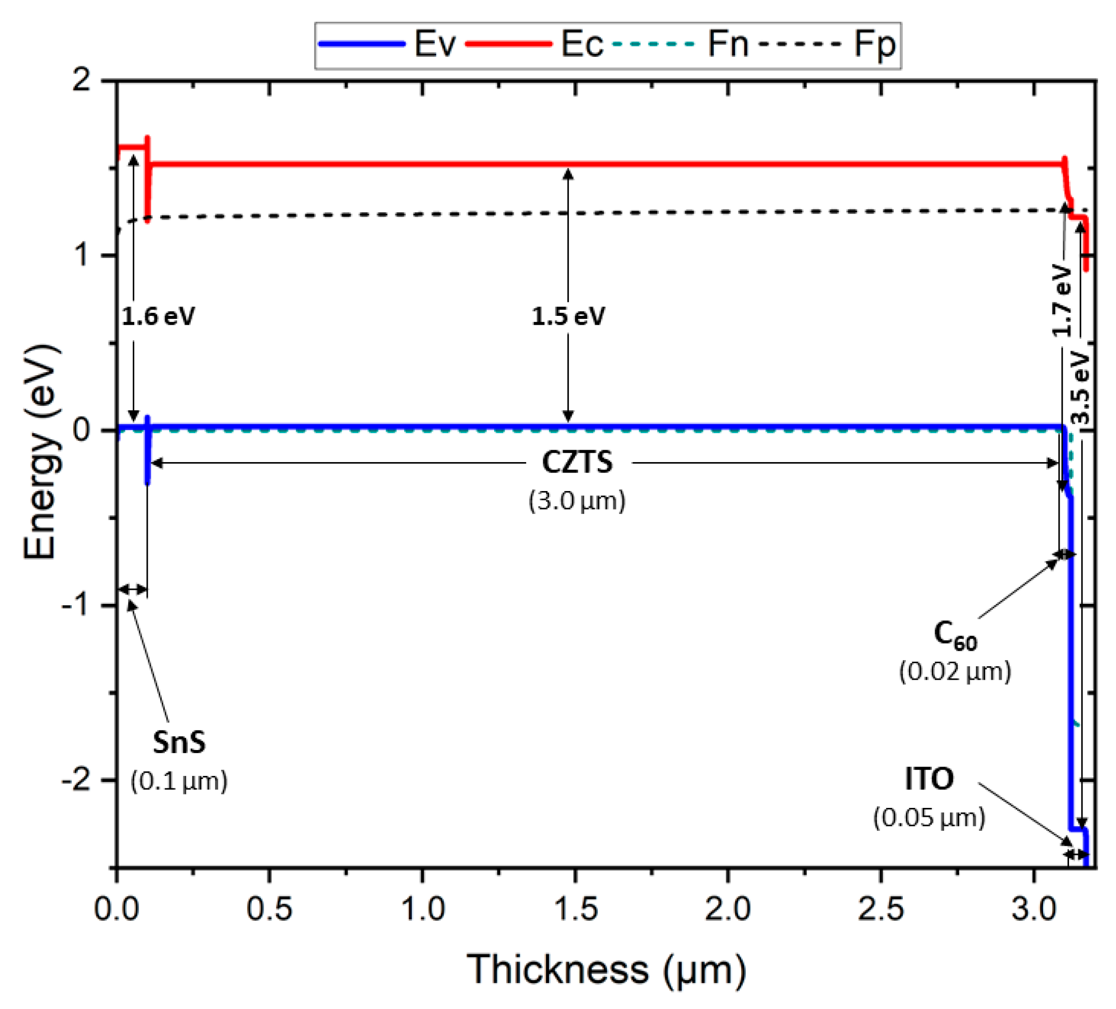
Figure 2 shows the band diagram of the introduced heterostructure to illustrate its band bending and quasi-Fermi levels. Here, the two solid lines in blue and red indicate the valance band and conduction band, respectively. Fn and Fp indicate the electron–hole pair generation in this device.

3.2. Effect of Absorber Layer Thickness and Acceptor Concentration on PV Performance

The principal design specifications that affect solar cell activities are the absorber concentration and absorber layer thickness. The acceptor concentration (NA) and absorber layer thickness must be adjusted to achieve optimal solar cell performance. To assess the cell performance, the absorber layer thickness and acceptor concentration were adjusted in 4 steps, from 1.5 μm to 3.0 μm and from 6 × 1015 cm−3 to 6 × 1018 cm−3, respectively. The dual effects of the absorber layer thickness and concentration on the PV parameters VOC, JSC, FF, and %η in the structure under assessment, Al/ITO/C60/CZTS/SnS/Pt, are presented in Figure 3. The figure indicates that the absorber layer concentration is a key component of the cell performance, and adjusting the absorber layer and CZTS acceptor concentration can alter the %η. Figure 3a–d show the open-circuit voltage, short-circuit current, fill factor, and efficiency.
Figure 3a shows that although the open-circuit voltage fluctuates in response to modifications in the acceptor concentration, it is mostly unaffected by changes in the absorber thickness. Additionally, the concentration of 6 × 10¹⁶ is followed by an increased range of open-circuit voltages. This can be attributed to the drop in the reverse saturation current that occurs with increased carrier concentrations, which increases the VOC. Figure 3b illustrates how the short-circuit current decreases with the acceptor concentration but slightly increases with the thickness. The increase in the short-circuit current observed with the increasing CZTS thickness and decreasing acceptor concentration can be attributed to the enhanced absorption of longer-wavelength photons within this layer. In Figure 3c, the fill factor exhibits behavior similar to that of the open-circuit voltage, although it is not assigned the same value at every thickness. Additionally, the key output efficiency increases at the concentrations of 6 × 10¹⁷ to 6 × 10¹⁸ and the thickness increases significantly. The fill factor (FF) shows a slight drop when the CZTS layer thickness grows, and the acceptor concentration is reduced. This is mostly due to an increase in the device’s series resistance. Although it is difficult to sustain high doping for every material, CZTS exhibits superior efficiency at higher doping levels. However, this value is still limited since the highest value that we can obtain is 1022.
In summary, every output displays the maximum range of values at the highest thickness. Furthermore, three outputs, excluding the short-circuit current, show the maximum values following the concentration of 6 × 1017 cm−3. Although the outcomes of this study are obtained at lower concentrations compared to previous research, 6 × 10¹⁸ is recommended as the optimal value for comparable performance.
Table 5 provides an overview of the optimal input conditions and final outcomes obtained from this proposed structure. These output parameters outperform those of earlier CZTS-based work, although the input values were kept consistent with past studies.
Figure 4 shows the normalized values of all outputs (VOC, JSC, FF, and %η), plotted against the acceptor concentration in Figure 4a and the thickness in Figure 4b. The normalized values are estimated based on the highest values of the individual outputs. The efficiency (%η) was obtained at the maximum while keeping the other outputs (VOC, JSC, and FF) satisfactory. The optimal input factors (thickness = 3 μm and NA = 6 × 1018 cm−3) result in a normalized value of %η = 1.0 and other normalized outcomes of 0.90 or higher.

3.2.1. Effect of Defect Density

Imperfections in a realistic active material are caused by dislocations and grain boundaries. These flaws act as carrier recombination centers, reducing the carrier lifetime and mobility. Figure 5 displays the combined effect of the defect density and absorber layer thickness on the solar cell performance to evaluate the device’s performance. The influence of the defect density between 1 × 1014 cm−3 and 1 × 1017 cm−3 and the thickness between 1.5 and 3.0 μm is explored in this study. Figure 5 illustrates how VOC fluctuates slightly with the thickness at a defect level below 1 × 1015 cm−3, where a regular variation in the defect density is noted. When the acceptor concentration is lower, VOC indicates its highest output; however, as the thickness increases, it also increases the value of VOC. The reducing behavior of JSC is quite similar to that of VOC. However, JSC reaches higher values when the thickness drops between 2.5 μm and 3.0 μm, and this value is affected by an increase in defects. Additionally, FF and η mostly follow the JSC and VOC outputs. The efficiency is roughly the same as the short-circuit current, although the fill factor is larger at moderate thickness values. When the defect density in the absorber layer surpasses 1 × 1016 cm−3, the cell performance deteriorates significantly. This decline is likely due to an increase in trap-assisted carrier recombination, as illustrated in the figure. The power conversion efficiency (PCE) decreases from 31.21% to 19.31%. According to this research, Shockley–Read–Hall (SRH) recombination significantly affects the loss of cell efficiency when the absorber layer contains many defects. This process involves carrier recombination in semiconductors through defect states within the bandgap. Such defects, often resulting from impurities or structural imperfections, can capture and recombine charge carriers (electrons and holes), thus lowering the overall efficiency of the semiconductor device. After combining these, we discovered that this absorber layer, with a greater thickness, can address the issue of lower outcomes, as shown at the above concentration. This can therefore continue to be increased because this range of thicknesses does not affect the experimental work.

3.2.2. Effect of Series and Shunt Resistance

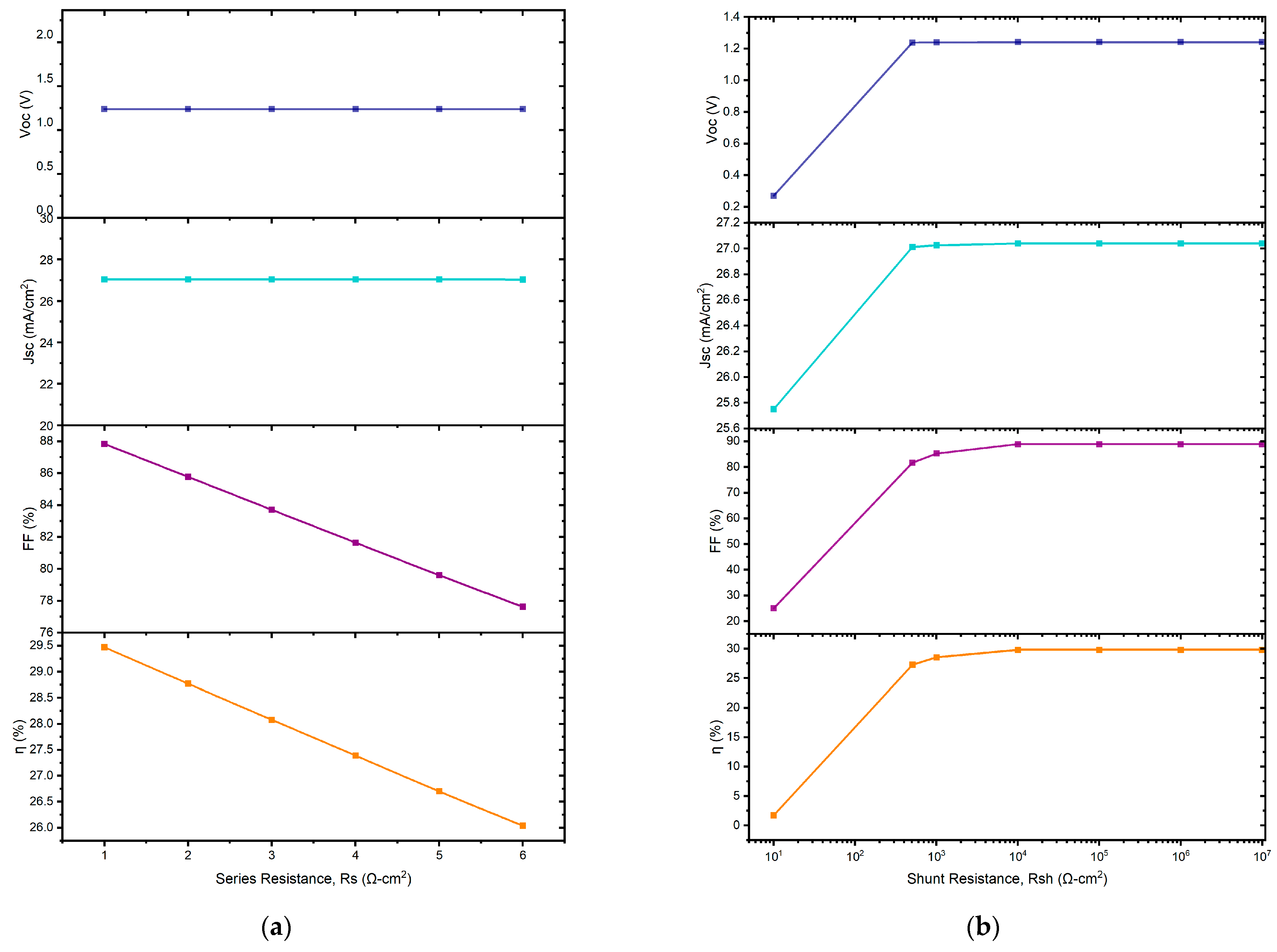
Series resistance (RS) and shunt resistance (RSh) have a substantial impact on the solar cell efficiency, primarily due to interlayer connections, metal contacts, and manufacturing defects within the cell structure. Figure 6 illustrates the variation in RS from 0 to 6 Ω-cm2, while keeping the shunt resistance constant at 1 × 10⁵ Ω-cm2 for the Al/ITO/C60/CZTS/SnS/Pt structure. During the RS variation, the power conversion efficiency (PCE) of the proposed device structure decreased. Specifically, as shown in Figure 6a, the PCE dropped from 29.5% to 26% as RS increased. Additionally, the fill factor (FF) value also decreased with the increase in RS. The JSC and VOC performance remained nearly constant with the increase in RS, indicating that the RS variation does not significantly impact these parameters for the studied device configurations. RS comprises the resistances between various terminals, such as the absorber, the ETL, the HTL, and the front and back contacts of the cell, which do not affect the current up to a certain threshold.
Series resistance (RS) originates from internal resistances, interface barriers, charge-collecting interlayers, and metal electrodes. In contrast, shunt resistance (RSh) is caused by leakage pathways like pinholes in the photoactive layer and recombination losses. The effect of the VOC, JSC, FF, and PCE values with RSh variation is visually represented in Figure 6b, with RSh ranging from 101 to 107 Ω-cm2. The VOC, JSC, FF, and PCE values displayed a similar trend with increasing shunt resistance (RSh). All performance parameters rose rapidly from 101 Ω-cm2 to 103 Ω-cm2 and then stabilized as RSh continued to increase.

3.2.3. Effect of Temperature

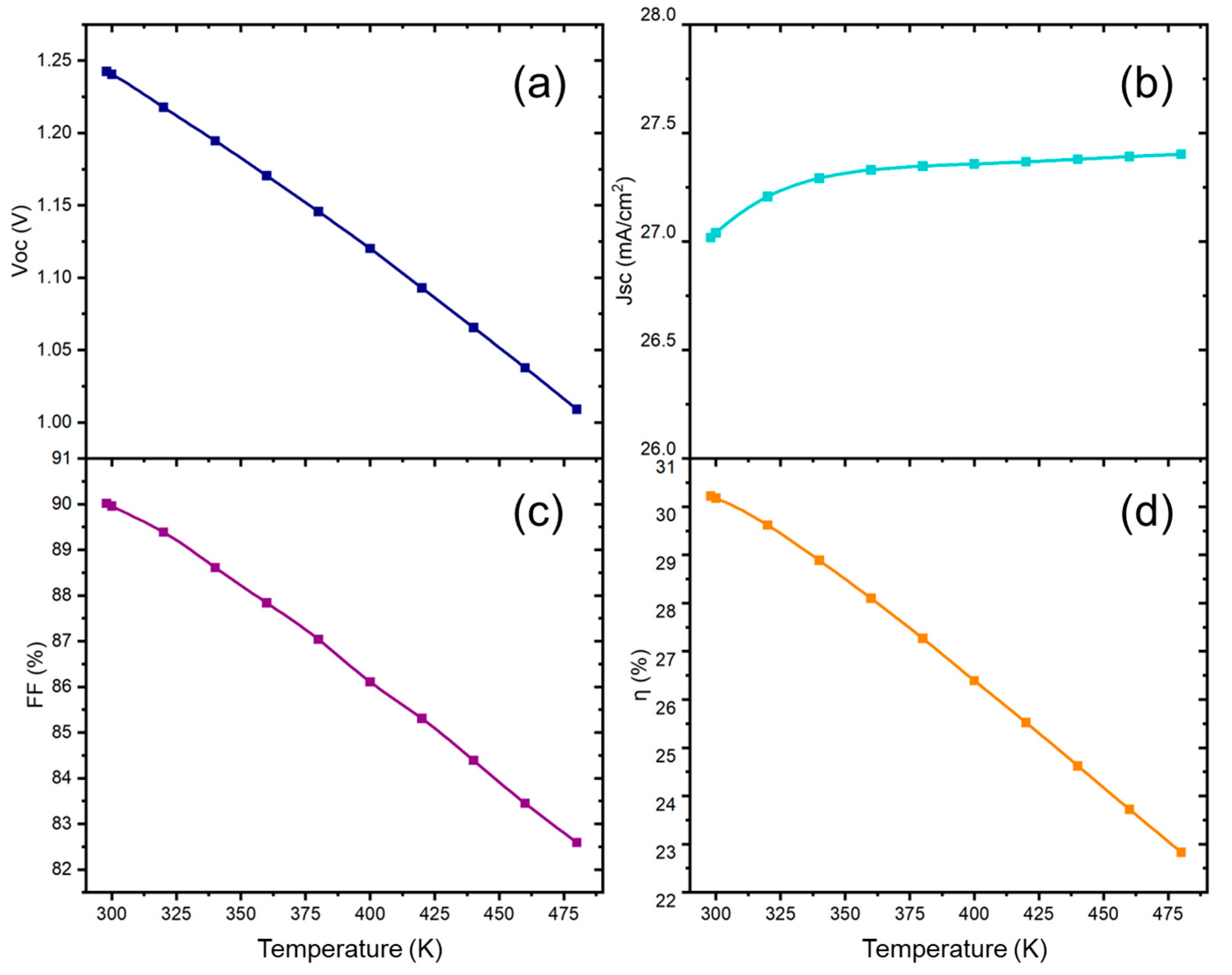
A thorough understanding of the solar cell’s performance at elevated operating temperatures is crucial in assessing its stability. High temperatures typically cause layer distortion, resulting in performance instability in most solar cell designs. To investigate the effect of the temperature on the solar cell efficiency, the temperature range was adjusted from 298 K to 480 K. Figure 7a,c,d demonstrate that with rising temperatures, the power conversion efficiency (PCE), fill factor (FF), and open-circuit voltage (VOC) decrease across the solar cell configurations. However, in Figure 7b, the short-circuit current (JSC) exhibits a slight upward variation, increasing marginally from 27 to 27.4 mA/cm2, contrasting with the more pronounced decreases observed in the other parameters. Nevertheless, the open-circuit voltage (VOC) decreased for the optimal device configurations as the temperature increased. This was due to the inverse relationship between VOC and the reverse saturation current density, J 0 . As the temperature rises, J 0 increases, as shown in Equation (4), which illustrates the relationship between VOC and J 0 .
V O C = A k B T 1 q l n 1 + J S C J 0
In this equation, k B T 1 q represents the thermal voltage, where k B is the Boltzmann constant, q is the electron charge, and A denotes the ideality factor.
Additionally, as the temperature of the model increases, the material defects are exacerbated, leading to a further decrease in VOC. Figure 7b demonstrates that the current increases slightly due to the reduction in the bandgap with the rising temperature. However, this increase is minimal, and the change in current remains nearly constant as the temperature continues to rise.

3.2.4. Effect of Capacitance and Mott–Schottky

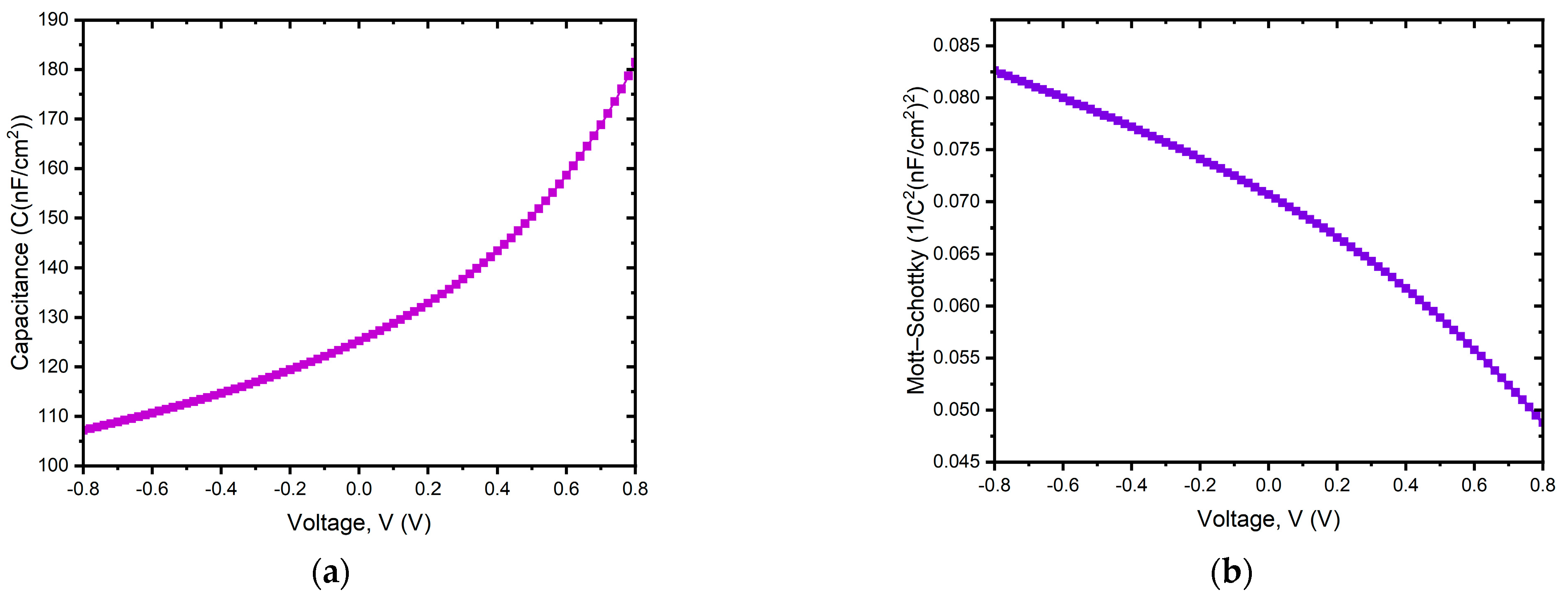
Figure 8a,b illustrates the capacitance per unit area (C) and the Mott–Schottky (M–S) plot as functions of the bias voltage (V), respectively. From these CV measurements, the built-in voltage (Vbi) and charge carrier density (Nd) can be derived using the established M–S analysis method. This technique is traditionally applied to semiconductor devices with fixed depletion layers and space charge regions, such as those with p–n junctions or semiconductor/metal interfaces. Equation (5) provides the value of the junction capacitance per unit area (C).
1 C 2 = 2 ε 0 ε r q N d ( V b i V )
Here, ε 0 represents the vacuum permittivity, ε r denotes the donor’s dielectric constant, and V stands for the applied voltage (Figure 8b).
The donor density (Nd) is derived from the slope of the linear segment, while the built-in voltage Vbi is determined by extrapolating the linear portion to intersect the voltage axis. This device exhibits voltage-independent capacitance ranging from −0.4 V to 0.5 V, with an exponential increase observed beyond 0.5 V (Figure 8a).

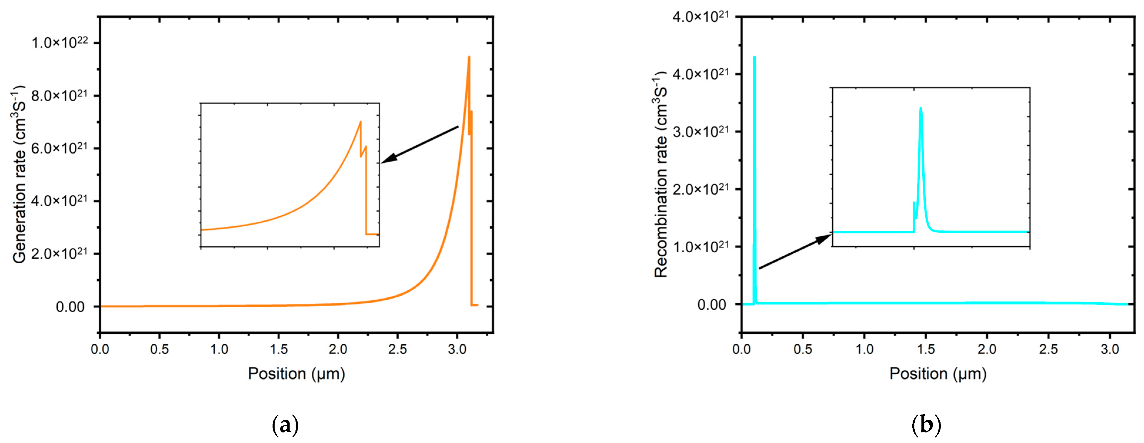
3.2.5. Effect of Generation and Recombination Rate

Figure 9a,b depicts the rates of carrier generation and recombination, respectively. During carrier generation, electron–hole pairs are formed as electrons are excited from the valence band to the conduction band, leaving behind holes in the valence band. This generation process results from the emission of electrons and holes.
Recombination is the reverse of generation, where electrons and holes from the conduction band pair up and are annihilated. The recombination rate in a solar cell is influenced by the charge carrier’s lifespan and density. Initially, electron–hole recombination is reduced due to defect states within the absorber layer. These defect states create energy levels that affect the electron–hole recombination profile within the solar cell structure. Consequently, the recombination rate distribution is non-uniform, as indicated in Figure 9b, due to imperfections and grain boundaries.

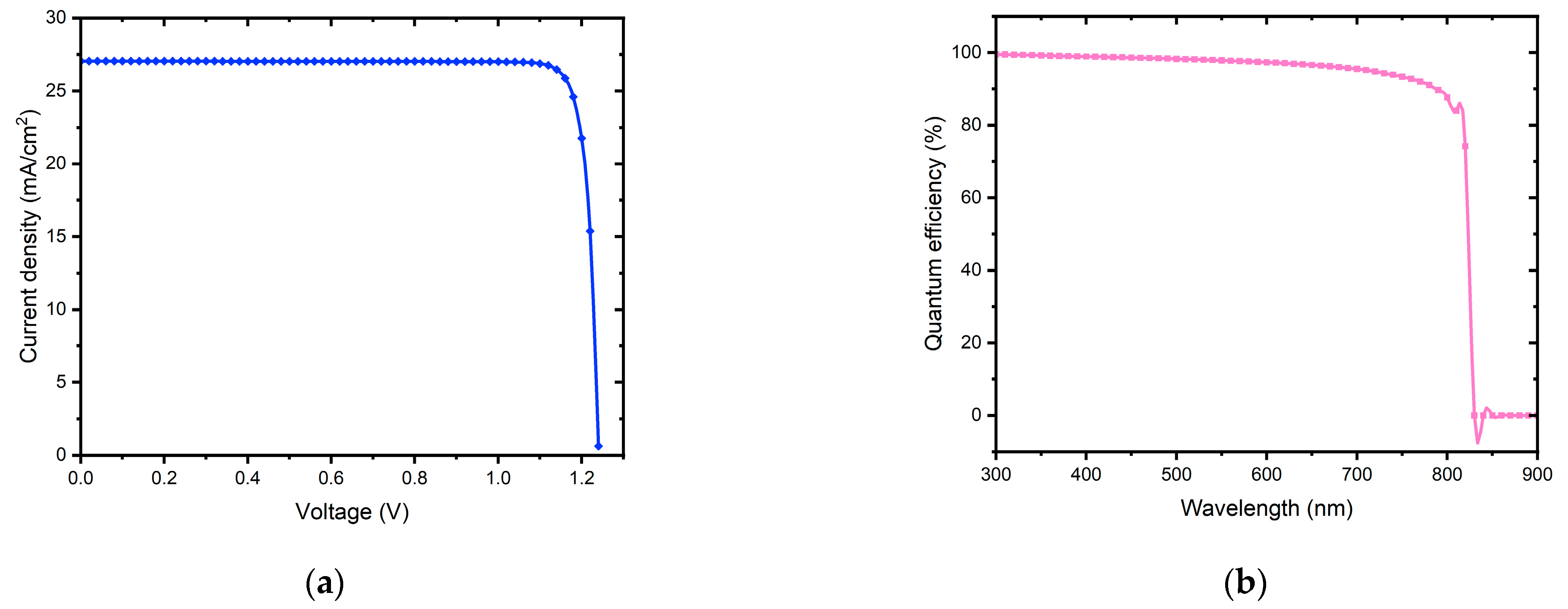
3.2.6. J–V and QE Characteristics

Figure 10a shows the J–V characteristic changing pattern of the proposed structure. The current density exhibits a high value of 27 mA/cm2. In addition, the voltage is higher than 1.0 V, which indicates that the structure exhibits better performance.
Figure 10b illustrates the quantum efficiency (QE) curve across different wavelengths. The proposed configuration achieved a peak QE close to 100% at a wavelength of 300 nm. However, recombination, which prevents charge carriers from entering the external circuit, generally reduces the QE of most solar cells. The QE is influenced by the same factors that affect the collection probability. For example, modifications to the front surface can impact carriers generated near the surface. Additionally, highly doped front surface layers can lead to free carrier absorption, which decreases the QE at longer wavelengths.

4. Conclusions

This numerical work has been performed using several input parameters that lead to unique characteristics for different materials. From these parameters—the thickness, bandgap, electron affinity, dielectric permittivity, CB/VB effective density of states, electron–hole thermal velocity, electron–hole mobility, and acceptor/donor concentration—we have optimized the thickness and acceptor concentration for the absorber layer. Additionally, in this work, we sought to examine how the proposed structure behaved with defects and minorities. Thus, after optimizing two input parameters, the thickness and acceptor concentration, we tuned the layer defects and set the appropriate band-to-band recombination (auger hole–electron capture coefficient) and three interface defects. Finally, the calculated results (open-circuit voltage, short-circuit current, fill factor, and efficiency) for the optimized structure were obtained as 1.2405 V, 27.039539 mA/cm2, 89.96%, and 30.18%, respectively, which are comparatively better than those obtained in preceding studies. However, in this study, the optimized input parameters were maintained according to previous studies. It is hoped that the accuracy and reliability of our method will inspire researchers to conduct further experimental work.

Author Contributions

Conceptualization, J.A.R. and M.A.I.; methodology, J.A.R. and M.A.I.; software, J.A.R. and M.A.I.; validation, J.A.R., M.A.I., M.H. and Y.I.; formal analysis, J.A.R., M.A.I., S.M., M.H., Y.I. and M.A.U.; investigation, J.A.R., M.A.I., S.M., M.H., Y.I. and M.A.U.; resources, J.A.R. and M.A.I.; data curation, J.A.R. and M.A.I.; writing—original draft preparation, J.A.R., M.A.I. and S.M.; writing—review and editing, J.A.R., M.A.I. and M.H.; visualization, J.A.R., M.A.I., S.M., M.H., Y.I. and M.A.U.; supervision, M.H., Y.I. and M.A.U. All authors have read and agreed to the published version of the manuscript.

Funding

This research received no external funding.

Data Availability Statement

Data are contained within the article.

Conflicts of Interest

The authors declare no conflicts of interest.

References

  1. Suryawanshi, M.P.; Agawane, G.L.; Bhosale, S.M.; Shin, S.W.; Patil, P.S.; Kim, J.H.; Moholkar, A.V. CZTS Based Thin Film Solar Cells: A Status Review. Mater. Technol. 2013, 28, 98–109. [Google Scholar] [CrossRef]
  2. Vallisree, S.; Thangavel, R.; Lenka, T.R. Theoretical Investigations on Enhancement of Photovoltaic Efficiency of Nanostructured CZTS/ZnS/ZnO Based Solar Cell Device. J. Mater. Sci. Mater. Electron. 2018, 29, 7262–7272. [Google Scholar] [CrossRef]
  3. Reshak, A.H.; Nouneh, K.; Kityk, I.V.; Bila, J.; Auluck, S.; Kamarudin, H.; Sekkat, Z. Structural, Electronic and Optical Properties in Earth- Abundant Photovoltaic Absorber of Cu2ZnSnS4 and Cu2ZnSnSe4 from DFT Calculations. Int. J. Electrochem. Sci. 2014, 9, 955–974. [Google Scholar] [CrossRef]
  4. Mekhilef, S.; Saidur, R.; Safari, A. A Review on Solar Energy Use in Industries. Renew. Sustain. Energy Rev. 2011, 15, 1777–1790. [Google Scholar] [CrossRef]
  5. Hosenuzzaman, M.; Rahim, N.A.; Selvaraj, J.; Hasanuzzaman, M.; Malek, A.B.M.A.; Nahar, A. Global Prospects, Progress, Policies, and Environmental Impact of Solar Photovoltaic Power Generation. Renew. Sustain. Energy Rev. 2015, 41, 284–297. [Google Scholar] [CrossRef]
  6. Graetzel, M.; Janssen, R.A.J.; Mitzi, D.B.; Sargent, E.H. Materials Interface Engineering for Solution-Processed Photovoltaics. Nature 2012, 488, 304–312. [Google Scholar] [CrossRef] [PubMed]
  7. Gupta, S. An Evolution Review in Solar Photovoltaic Materials. J. Commun. Technol. Electron. Comput. Sci. 2018, 20, 7–15. [Google Scholar]
  8. Jaiswal, D.; Mittal, M.; Mittal, V. A Review on Solar PV Cell and Its Evolution. In Proceedings of the Latest Trends in Renewable Energy Technologies; Vadhera, S., Umre, B.S., Kalam, A., Eds.; Springer: Singapore, 2021; pp. 303–313. [Google Scholar]
  9. Mitzi, D.B.; Gunawan, O.; Todorov, T.K.; Wang, K.; Guha, S. The Path towards a High-Performance Solution-Processed Kesterite Solar Cell. Sol. Energy Mater. Sol. Cells 2011, 95, 1421–1436. [Google Scholar] [CrossRef]
  10. ur Rehman, A.; Iqbal, M.Z.; Bhopal, M.F.; Khan, M.F.; Hussain, F.; Iqbal, J.; Khan, M.; Lee, S.H. Development and Prospects of Surface Passivation Schemes for High-Efficiency c-Si Solar Cells. Sol. Energy 2018, 166, 90–97. [Google Scholar] [CrossRef]
  11. Irvine, S. Solar Cells and Photovoltaics. In Springer Handbook of Electronic and Photonic Materials; Kasap, S., Capper, P., Eds.; Springer International Publishing: Cham, Switzerland, 2017; pp. 1097–1109. ISBN 978-3-319-48933-9. [Google Scholar]
  12. Gunaicha, P.P.; Gangam, S.; Roehl, J.L.; Khare, S.V. Structural, Energetic and Elastic Properties of Cu2ZnSn(SxSe1−x)4 (x = 1, 0.75, 0.5, 0.25, 0) Alloys from First-Principles Computations. Sol. Energy 2014, 102, 276–281. [Google Scholar] [CrossRef]
  13. Simya, O.K.; Mahaboobbatcha, A.; Balachander, K. A Comparative Study on the Performance of Kesterite Based Thin Film Solar Cells Using SCAPS Simulation Program. Superlattices Microstruct. 2015, 82, 248–261. [Google Scholar] [CrossRef]
  14. Atwater, H.A.; Polman, A. Plasmonics for Improved Photovoltaic Devices. Nat. Mater 2010, 9, 205–213. [Google Scholar] [CrossRef] [PubMed]
  15. Green, M.; Dunlop, E.; Hohl-Ebinger, J.; Yoshita, M.; Kopidakis, N.; Hao, X. Solar Cell Efficiency Tables (Version 57). Prog. Photovolt. Res. Appl. 2021, 29, 3–15. [Google Scholar] [CrossRef]
  16. Green, M.A.; Emery, K.; Hishikawa, Y.; Warta, W. Solar Cell Efficiency Tables (Version 37). Prog. Photovolt. Res. Appl. 2011, 19, 84–92. [Google Scholar] [CrossRef]
  17. Kayes, B.M.; Nie, H.; Twist, R.; Spruytte, S.G.; Reinhardt, F.; Kizilyalli, I.C.; Higashi, G.S. 27.6% Conversion Efficiency, a New Record for Single-Junction Solar Cells under 1 Sun Illumination. In Proceedings of the 2011 37th IEEE Photovoltaic Specialists Conference, Seattle, WA, USA, 19–24 June 2011; pp. 000004–000008. [Google Scholar]
  18. Green, M.A.; Emery, K.; Hishikawa, Y.; Warta, W.; Dunlop, E.D. Solar Cell Efficiency Tables (Version 43). Prog. Photovolt. Res. Appl. 2014, 22, 1–9. [Google Scholar] [CrossRef]
  19. Mitzi, D.B.; Yuan, M.; Liu, W.; Kellock, A.J.; Chey, S.J.; Deline, V.; Schrott, A.G. A High-Efficiency Solution-Deposited Thin-Film Photovoltaic Device. Adv. Mater. 2008, 20, 3657–3662. [Google Scholar] [CrossRef]
  20. Fthenakis, V.M.; Moskowitz, P.D. Photovoltaics: Environmental, Health and Safety Issues and Perspectives. Prog. Photovolt. Res. Appl. 2000, 8, 27–38. [Google Scholar] [CrossRef]
  21. Tanaka, A. Toxicity of Indium Arsenide, Gallium Arsenide, and Aluminium Gallium Arsenide. Toxicol. Appl. Pharmacol. 2004, 198, 405–411. [Google Scholar] [CrossRef]
  22. Phipps, G.; Mikolajczak, C.; Guckes, T. Indium and Gallium: Long-Term Supply. Renew. Energy Focus 2008, 9, 56–59. [Google Scholar] [CrossRef]
  23. Patel, M.; Ray, A. Enhancement of Output Performance of Cu2ZnSnS4 Thin Film Solar Cells—A Numerical Simulation Approach and Comparison to Experiments. Phys. B Condens. Matter 2012, 407, 4391–4397. [Google Scholar] [CrossRef]
  24. Nitsche, R.; Sargent, D.F.; Wild, P. Crystal Growth of Quaternary 122464 Chalcogenides by Iodine Vapor Transport. J. Cryst. Growth 1967, 1, 52–53. [Google Scholar] [CrossRef]
  25. Lahoual, M.; Bourennane, M.; Aidaoui, L. Numerical Investigation of Copper Zinc Tin Sulphide Based Solar Cell with Non-Toxic Zn (O, S) Buffer Layer. Phys. Status Solidi 2024, 221, 2300732. [Google Scholar] [CrossRef]
  26. Mansouri, S.; Dehimi, L.; Bencherif, H.; Pezzimenti, F.; Zulfiqar, M.; Alotaibi, N.H.; Mohammad, S.; Haldhar, R.; Darwish, M.A.; Hossain, M.K. Theoretical Simulation on Enhancing the Thin-Film Copper Zinc Tin Sulfide Solar Cell Performance Using MoS2, MoOx, and CuI as Efficient Hole Transport Layers. Energy Fuels 2024, 38, 8187–8198. [Google Scholar] [CrossRef]
  27. Dakua, P.K.; Dash, R.K.; Laidouci, A.; Bhattarai, S.; Dudekula, U.; Kashyap, S.; Agarwal, V.; Rashed, A.N.Z. Evaluating CZTS Solar Cell Performance Based on Generation and Recombination Models for Possible ETLs Through Numerical Analysis. J. Electron. Mater. 2024, 53, 2015–2025. [Google Scholar] [CrossRef]
  28. Sawa, H.B.; Babucci, M.; Keller, J.; Björkman, C.P.; Samiji, M.E.; Mlyuka, N.R. Toward Improving the Performance of Cu2ZnSnS4-Based Solar Cells with Zr, W or Sulfurized Layers at the SnO2:F/Cu2ZnSnS4 Rear Interface. Thin Solid Film. 2024, 793, 140276. [Google Scholar] [CrossRef]
  29. Kissin, S.A.; Owens, D.A.R. The Relatives of Stannite in the Light of New Data. Can. Mineral. 1989, 27, 673–688. [Google Scholar]
  30. Nakazawa, K.I. Electrical and Optical Properties of Stannite-Type Quaternary Semiconductor Thin Films. Jpn. J. Appl. Phys. 1988, 27, 2094. [Google Scholar] [CrossRef]
  31. Cherouana, A.; Labbani, R. Study of CZTS and CZTSSe Solar Cells for Buffer Layers Selection. Appl. Surf. Sci. 2017, 424, 251–255. [Google Scholar] [CrossRef]
  32. Niki, S.; Contreras, M.; Repins, I.; Powalla, M.; Kushiya, K.; Ishizuka, S.; Matsubara, K. CIGS Absorbers and Processes. Prog. Photovolt. Res. Appl. 2010, 18, 453–466. [Google Scholar] [CrossRef]
  33. Amin, N.; Hossain, M.I.; Chelvanathan, P.; Mukter Uzzaman, A.S.M.; Sopian, K. Prospects of Cu2ZnSnS4 (CZTS) Solar Cells from Numerical Analysis. In Proceedings of the International Conference on Electrical & Computer Engineering (ICECE 2010), Dhaka, Bangladesh, 18–20 December 2010; pp. 730–733. [Google Scholar]
  34. Shin, B.; Gunawan, O.; Zhu, Y.; Bojarczuk, N.A.; Chey, S.J.; Guha, S. Thin Film Solar Cell with 8.4% Power Conversion Efficiency Using an Earth-Abundant Cu2ZnSnS4 Absorber. Prog. Photovolt. Res. Appl. 2013, 21, 72–76. [Google Scholar] [CrossRef]
  35. Adewoyin, A.D.; Olopade, M.A.; Chendo, M. Enhancement of the Conversion Efficiency of Cu2ZnSnS4 Thin Film Solar Cell through the Optimization of Some Device Parameters. Optik 2017, 133, 122–131. [Google Scholar] [CrossRef]
  36. Siebentritt, S. Why Are Kesterite Solar Cells Not 20% Efficient? Thin Solid Film. 2013, 535, 1–4. [Google Scholar] [CrossRef]
  37. Zanatta, A.R. The Shockley–Queisser Limit and the Conversion Efficiency of Silicon-Based Solar Cells. Results Opt. 2022, 9, 100320. [Google Scholar] [CrossRef]
  38. Shockley, W.; Queisser, H. Detailed Balance Limit of Efficiency of p–n Junction Solar Cells. In Renewable Energy; Routledge: London, UK, 2011; ISBN 978-1-315-79324-5. [Google Scholar]
  39. Lv, Z.; Deng, Z.; Xu, D.; Li, X.; Jia, Y. Efficient Organic Light-Emitting Diodes with C60 Buffer Layer. Displays 2009, 30, 23–26. [Google Scholar] [CrossRef]
  40. Ferhati, H.; Djeffal, F.; AbdelMalek, F. Towards Improved Efficiency of SnS Solar Cells Using Back Grooves and Strained-SnO2 Buffer Layer: FDTD and DFT Calculations. J. Phys. Chem. Solids 2023, 178, 111353. [Google Scholar] [CrossRef]
  41. Isha, A.; Kowsar, A.; Kuddus, A.; Hossain, M.K.; Ali, M.H.; Haque, M.D.; Rahman, M.F. High Efficiency Cu2MnSnS4 Thin Film Solar Cells with SnS BSF and CdS ETL Layers: A Numerical Simulation. Heliyon 2023, 9, e15716. [Google Scholar] [CrossRef]
  42. Gohri, S.; Sharma, S.; Pandey, R.; Madan, J.; Sharma, R. Influence of SnS and Sn2S3 Based BSF Layers on the Performance of CZTSSe Solar Cell. In Proceedings of the 2020 47th IEEE Photovoltaic Specialists Conference (PVSC), Calgary, AB, Canada, 15 June–21 August 2020; pp. 2300–2303. [Google Scholar]
  43. Srivastava, A.; Dua, P.; Lenka, T.R.; Tripathy, S.K. Numerical Simulations on CZTS/CZTSe Based Solar Cell with ZnSe as an Alternative Buffer Layer Using SCAPS-1D. Mater. Today Proc. 2021, 43, 3735–3739. [Google Scholar] [CrossRef]
  44. Burgelman, M.; Nollet, P.; Degrave, S. Modelling Polycrystalline Semiconductor Solar Cells. Thin Solid Film. 2000, 361–362, 527–532. [Google Scholar] [CrossRef]
  45. Oublal, E.; Ait Abdelkadir, A.; Sahal, M. High Performance of a New Solar Cell Based on Carbon Nanotubes with CBTS Compound as BSF Using SCAPS-1D Software. J. Nanopart. Res. 2022, 24, 202. [Google Scholar] [CrossRef]
  46. Rahman, M.A. Design and Simulation of a High-Performance Cd-Free Cu2SnSe3 Solar Cells with SnS Electron-Blocking Hole Transport Layer and TiO2 Electron Transport Layer by SCAPS-1D. SN Appl. Sci. 2021, 3, 253. [Google Scholar] [CrossRef]
  47. Mohandes, A.; Moradi, M.; Kanani, M. Numerical Analysis of High Performance Perovskite Solar Cells with Stacked ETLs/C60 Using SCAPS-1D Device Simulator. Opt. Quant. Electron. 2023, 55, 533. [Google Scholar] [CrossRef]
  48. Atowar Rahman, M. Enhancing the Photovoltaic Performance of Cd-Free Cu2ZnSnS4 Heterojunction Solar Cells Using SnS HTL and TiO2 ETL. Sol. Energy 2021, 215, 64–76. [Google Scholar] [CrossRef]
  49. Islam, M.A.; Al Rafi, J.; Uddin, M.A. Modeling and Formation of a Single-Walled Carbon Nanotube (SWCNT) Based Heterostructure for Efficient Solar Energy: Performance and Defect Analysis by Numerical Simulation. AIP Adv. 2023, 13, 115201. [Google Scholar] [CrossRef]
  50. Uddin, M.A.; Rafi, J.A.; Islam, M.A.; Mominuzzaman, S.M.; Nath, I.D. Modeling and Numerical Analysis of Heterostructure Single-Walled Carbon Nanotube (SWCNT) Solar Cell. In Proceedings of the 2022 12th International Conference on Electrical and Computer Engineering (ICECE), Dhaka, Bangladesh, 21–23 December 2022; pp. 388–391. [Google Scholar]
Figure 1. Structural model of the proposed solar cell device (Al/ITO/C60/CZTS/SnS/Pt).
Electronicmat 05 00010 g001
Figure 2. Energy band diagram of the proposed heterostructure cell—ITO/C60/CZTS/SnS.
Electronicmat 05 00010 g002
Figure 3. Simultaneous implications of acceptor concentration and thickness of absorber layer on performance ((a) VOC, (b) JSC, (c) FF, and (d) %η) of CZTS-based solar cell.
Electronicmat 05 00010 g003
Figure 4. Normalized values of solar cell output parameters as a function of (a) acceptor concentration and (b) thickness.
Electronicmat 05 00010 g004
Figure 5. Impact of defect density and absorber layer thickness on PV performance parameters ((a) VOC, (b) JSC, (c) FF, and (d) %η) of CZTS-based solar cell.
Electronicmat 05 00010 g005
Figure 6. Impact of (a) series and (b) shunt resistance on PV performance (VOC, JSC, FF, and PCE).
Electronicmat 05 00010 g006
Figure 7. Effect of temperature on solar cell performance parameters: (a) open-circuit voltage (VOC), (b) short-circuit current (JSC), (c) fill factor (FF), and (d) efficiency (η%).
Electronicmat 05 00010 g007
Figure 8. (a) Capacitance (C) and (b) Mott–Schottky (1/C2) plot for the proposed structure.
Electronicmat 05 00010 g008
Figure 9. (a) Generation rate and (b) recombination rate for the proposed structure.
Electronicmat 05 00010 g009
Figure 10. (a) J–V characteristics and (b) quantum efficiency (QE) plot of the proposed structure.
Electronicmat 05 00010 g010
Table 1. Parameters used to simulate the heterostructure cell ITO/C60/CZTS/SnS.
ParameterITO [46]C60 [47]CZTS [43]SnS [46]
Thickness (nm)50201500–3000100
Bandgap Eg (eV)3.51.71.51.6
Electron affinity, χ (eV)4.64.54.584.1
Dielectric permittivity8.96.09.513.0
CB effective density of states (cm−3)2.2 × 10181.0 × 10191.91 × 10182.18 × 1018
VB effective density of states (cm−3)1.8 × 10191.0 × 10192.58 × 10184.46 × 1018
Electron thermal velocity (cm s−1)1.0 × 1071.0 × 1071.0 × 1071.0 × 107
Hole thermal velocity (cm s−1)1.0 × 1071.0 × 1071.0 × 1071.0 × 107
Electron mobility, μn (cm2 V−1 s−1)10505015
Hole mobility, μp (cm2 V−1 s−1)105010100
Donor concentration, ND (cm−3)1.0 × 10191.0 × 10180.00.0
Acceptor concentration, NA (cm−3)0.00.06.0 × 1015–6.0 × 10181.0 × 1019
Table 2. Front and back contact parameters.
ParameterFront Contact Electrical PropertiesBack Contact Electrical Properties
[Al][Pt]
Surface recombination velocity of electrons (cm s−1)1.0 × 1071.0 × 105
Surface recombination velocity of holes (cm s−1)1.0 × 1051.0 × 107
Work function (eV)4.265.65
Table 3. Interface defect parameters.
ParameterITO/C60C60/CZTSCZTS/SnS
Defect typeNeutralNeutralNeutral
Capture cross-section of electrons (cm2)1.0 × 10–191.0 × 10–191.0 × 10⁻¹⁹
Capture cross-section of holes (cm2)1.0 × 10–191.0 × 10–191.0 × 10⁻¹⁹
Energetic distributionSingleGaussianSingle
Total defect density (cm−2)1.0 × 10101.0 × 10101.0 × 1010
Table 4. Individual layers’ defect parameters.
ParameterAt Each Layer (ITO, C60, CZTS, SnS)
Defect typeNeutral
Capture cross-section of electrons (cm2)1.0 × 10⁻¹⁵
Capture cross-section of holes (cm2)1.0 × 10⁻¹⁵
Energetic distributionSingle
Reference for defect energy level EtAbove EV (SCAPS < 2.7)
Total density (cm−3): uniform1.0 × 1014–1.0 × 10¹⁷
Auger hole/electron capture coefficient (cm6 s−1)1.0 × 10⁻²⁶
Table 5. Optimum inputs (thickness and acceptor concentration) and outputs at optimum conditions.
Optimum Input ConditionsOutput Parameters at Optimized Input Conditions
W (μm)NA (cm−3)VOC (V)JSC (mA/cm2)FF (%)η (%)
3.06 × 10181.240527.03953989.9630.18
Disclaimer/Publisher’s Note: The statements, opinions and data contained in all publications are solely those of the individual author(s) and contributor(s) and not of MDPI and/or the editor(s). MDPI and/or the editor(s) disclaim responsibility for any injury to people or property resulting from any ideas, methods, instructions or products referred to in the content.