Article

25,000 fps Computational Ghost Imaging with Ultrafast Structured Illumination

Department of Opto-Electronic Engineering, Beihang University, Beijing 100191, China
*
Author to whom correspondence should be addressed.
Electron. Mater. 2022, 3(1), 93-100; https://doi.org/10.3390/electronicmat3010009
Submission received: 31 December 2021 / Revised: 9 February 2022 / Accepted: 17 February 2022 / Published: 24 February 2022
(This article belongs to the Special Issue Feature Papers of Electronic Materials)

Abstract

:
Computational ghost imaging, as an alternative photoelectric imaging technology, uses a single-pixel detector with no spatial resolution to capture information and reconstruct the image of a scene. Due to its essentially temporal measurement manner, improving the image frame rate is always a major concern in the research of computational ghost imaging technology. By taking advantage of the fast switching time of LED, an LED array was developed to provide a structured illumination light source in our work, which significantly improves the structured illumination rate in the computational ghost imaging system. The design of the LED array driver circuit presented in this work makes full use of the LED switching time and achieves a pattern displaying rate of 12.5 MHz. Continuous images with 32 × 32 pixel resolution are reconstructed at a frame rate of 25,000 fps, which is approximately 500 times faster than what a universally used digital micromirror device can achieve. The LED array presented in this work can potentially be applied to other techniques requiring high-speed structured illumination, such as fringe 3D profiling and array-based LIFI.

1. Introduction

Compared with the conventional imaging method using a sensor array, the most prominent feature of the computational ghost imaging technique [1,2] is that only a single-pixel sensor is needed to obtain a two-dimensional image, which gives it the advantages of high sensitivity, anti-defocus, flexible design and high robustness. Computational ghost imaging has become one of the research hotspots of advanced optical imaging in recent years and has been applied to laser radar [3,4,5], target seeking [6], three-dimensional profiling [7,8,9,10], multispectral imaging [11,12,13], etc.
A computational ghost imaging system consists of three parts: an illumination modulation module, a light intensity detection module and an image reconstruction module. A spatial light modulator (SLM) and a light source constitute the illumination modulation module and create a structured light field with deterministic patterns. The modulated light field is projected onto the object by an imaging lens. The total light intensity carrying the information of the object is recorded by the detection module and can be combined with the known modulated illumination information to compute a digital image using the image reconstruction module. Computational ghost imaging systems can be applied to dynamic imaging scenarios, such as living cell imaging and video surveillance. As computational ghost imaging trades temporal resolution for spatial resolution, high requirements are put forward for the imaging frame rate of computational ghost imaging systems.
A high-speed SLM is the core device in a computational ghost imaging system, and its modulation speed has always been a bottleneck limiting the speed of computational ghost imaging systems. Many schemes have been proposed based on different SLMs, such as digital micromirror devices (DMDs) [14,15,16], liquid crystal displays (LCDs) [17] and optical phased arrays (OPAs) [18,19]. The design and manufacturing process of an OPA is complex and difficult, and the response frequency of an LCD can only reach about 1 KHz. Although DMDs are the fastest existing SLM at a resolution of 32 × 32 pixel, the highest modulation speed can only reach about 20 KHz. To solve this problem, an LED array module is proposed as an alternative to the combination of an SLM and a light source due to its ultrafast structured illumination rate, which greatly improves the imaging speed of the system. The smaller area of a single LED not only makes the LED array occupy less space but also makes the single LED switch faster. In recent years, the switching speed of micro-LEDs [20,21] has reached the nanosecond level due to their area of tens of square microns, but the cost is high due to the complex technology for the fabrication of micro-LED arrays and there are technical bottlenecks such as massive transfer. Therefore, LED chips with a small area of 1 mm × 1 mm were selected for our LED arrays. Additionally, advanced imaging schemes such as compressive sensing [22,23,24,25] can greatly reduce the number of samples. However, the scheme based on compressive sensing requires huge computation in the progress of reconstruction, so an evolutionary compressive sensing algorithm [26] is used to achieve a higher frame rate in our system. In this work, we develop an LED array as an illumination modulation module and greatly improve the speed of our imaging system, which reaches 25,000 fps at a resolution of 32 × 32 pixel. By optimizing and designing the driver circuit design, our system can make full use of the switching time of single LEDs and display patterns with a frequency of 12.5 MHz. The presented scheme can not only be used in high-speed dynamic imaging based on a computational ghost imaging system but can also be applied to other high-speed systems based on LED arrays, such as Light Fidelity (LIFI), which is a new communication method that uses LEDs to turn on and off at ultrafast speed to transmit information.

2. Materials and Methods

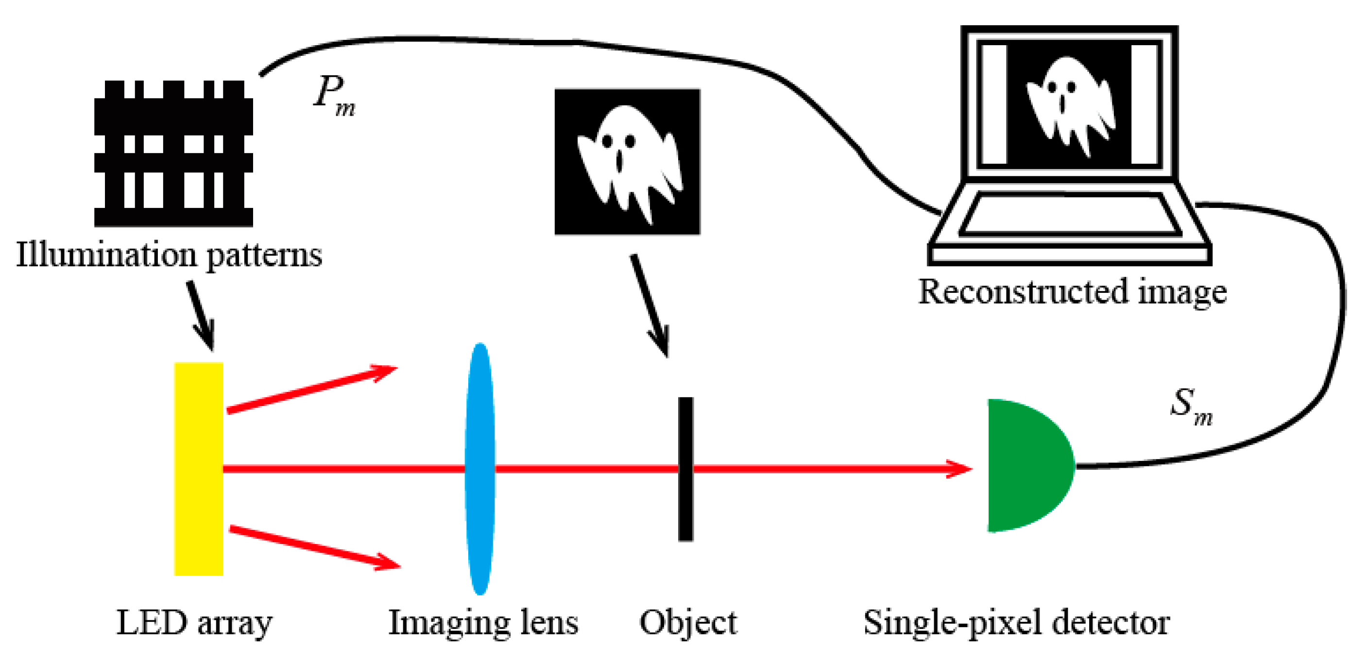
2.1. LED-Based Computational Ghost Imaging

In an LED-based computational ghost imaging system as shown in Figure 1, the illumination patterns and reconstruction algorithm greatly affect the imaging efficiency. In this work, continuous illuminating patterns are displayed by the LED array. A single modulation is assumed to be P m and its corresponding signal collected by a single-pixel detector is assumed to be S m . When orthonormal patterns are used as modulation patterns, the object image I with N pixels can be computed by only N measurements in the case of full sampling, and the reconstruction algorithm can be expressed as follows:
I = m = 1 N S m P m
The Hadamard matrix H ( N , N ) was chosen as the modulation matrix, not only because of the orthogonality of the Hadamard matrix, but also as it consists of only two values, 1 and −1, corresponding to the two states of LED: on and off. Mathematically, the sampling process can be described as follows:
S = H × O
where the transfer function vector of the object is assumed to be O = [ O 1 , O 2 , , O N ] T and the vector of the signal is assumed to be S = [ S 1 , S 2 , , S N ] T . Considering the Hermitian property and orthogonality of the Hadamard matrix [27], which is expressed as H × H T = N × I and H 1 = H T , Equation (2) is converted to the following:
O = 1 N × H 1 × S = 1 N × H T × S
Illuminating patterns P m are reshaped from the m th row/column of an N -order Hadamard matrix H T . The object image can be reconstructed with known H T and S .

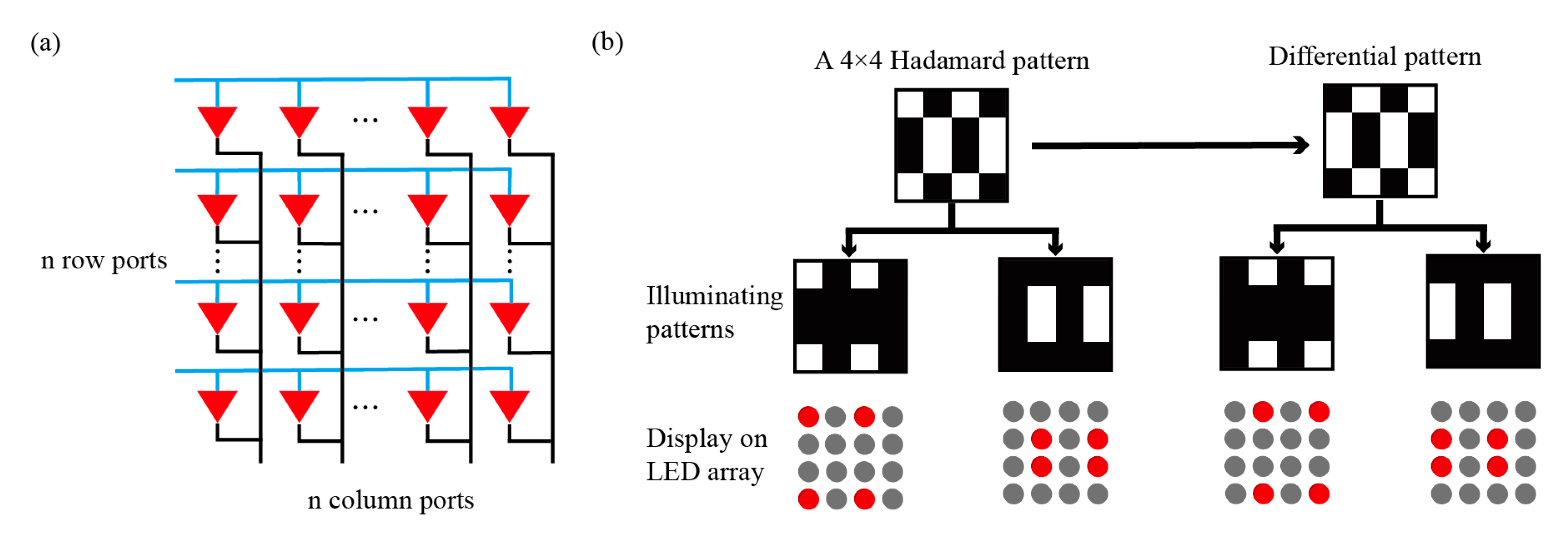
2.2. Monochromatic LED Illumination Module and Its Driver

The modulation speed of a light field is one of the main factors that limits the imaging rate of a computational ghost imaging system. An LED array was chosen as the illuminating module because the switching time of LEDs can reach tens of nanoseconds, which enables the LED array to display patterns at an extremely high speed. In our previous work [28], our designed LED-based illuminating module, which consisted of an LED array, a driver board and an FPGA, could provide illumination with a pattern displaying frequency of 1 MHz. Additionally, the imaging frame rate of the computational ghost imaging system reached 1000 fps in the dynamic experiment. A schematic diagram of the LED array design is shown in Figure 2a. Each port controls one row/column of LEDs, so that only 2 × n I/O ports are required to display illuminating patterns. The Hadamard patterns were chosen as the modulation patterns but cannot be directly displayed on the LED array. The display strategy is shown in Figure 2b; Hadamard patterns can be divided into two parts, which have good symmetry and can be sequentially displayed by our designed LED array. To suppress noise in the experiment, the differential pattern of the binary Hadamard pattern also needed to be displayed. In the same way, it can be separated and displayed as illuminating patterns.
Although the illuminating module achieved a good pattern displaying frequency in our previous work, the switching time of LED chips was not fully utilized due to the circuit drive design. In other words, the speed of the LED array did not reach its limit. To address this problem and improve the imaging speed of the system, we optimized the design of our system. First, new LED chips (Everlight, New Taipei City, China, SMD 18-038/RSGHBHC1-S02/2T, red light wavelength 619–631 nm, 1 mm × 1 mm, 20 mA, 60 mW) were used for our LED array. After testing, the switching time of a single LED chip was about 60 ns, and the theoretical flashing frequency could reach 16.7 MHz. Additionally, the size of the new LED array was reduced to a quarter compared with the old version. Second, a new design was used for the driver to make the flashing frequency of the illuminating module close to the theoretical maximum. As shown in Figure 3a, an example of a 2 × 2 pixel LED array and the circuit of the designed driver is presented.
In order to achieve the target imaging speed of the computational ghost imaging system, the driving board not only needs to make sure that the switching time of each component is faster than the LED but also needs to be able to withstand a large current. This is because the bandwidth of a silicon-based single-pixel detector is always inversely proportional to the size of the detection area. A small detection area inevitably leads to a long optical path and serious light intensity loss, which puts forward higher requirements for the light power provided by the LED array. The core component of the driving circuit is an MOS chip, which acts as a switch connecting the power supply/ground and LEDs. The I/O ports of the FPGA output a square wave signal to turn the MOS chip on or off. The reason why the I/O ports of an FPGA are not used to directly connect and control LEDs is that a single I/O port can only provide 30 mA current, which is far from meeting the power demand of the LED array. In the process of displaying illuminating patterns, the voltage of a single LED has four states, as shown in Figure 3b–d. The LED chip can be lit only at state 4, when the I/O R signal controlling the PMOS is low-voltage and the I/O C signal controlling the NMOS is high-voltage. For the other three states, the voltage drop of the LED needs to be below the LED threshold voltage. The choice of resistance affects not only the power consumption of the circuit board but also these four states. Though Figure 3c presents the voltage waveform when RR and RC take small resistance, in our illuminating module, it is recommended that RR and RC take a large resistance of K Ω level because of the lower power consumption. It is worth noting that the voltage of LEDs will increase at states 1, 2 and 3 as the resistance value of RR and RC increases when the modulated I/O signal is at a high frequency. While ensuring that V1, V2 and V3 are below the threshold voltage, an increase in V1, V2 and V3 enables the LED to reach the threshold voltage more quickly, which leads to a slightly shorter time from extinction to illumination for the LED. Additionally, the switching time among the four states is determined by the response time of the corresponding equivalent circuit in each state to the signal, which is not shown in Figure 3c. Importantly, a quarter of the total LEDs are lit when each illumination pattern (except the first four patterns) is displayed. This means that the total load is a constant when the LED array displays illuminating patterns, which greatly reduces the current adjustment requirement of the power supply.

3. Results and Discussion

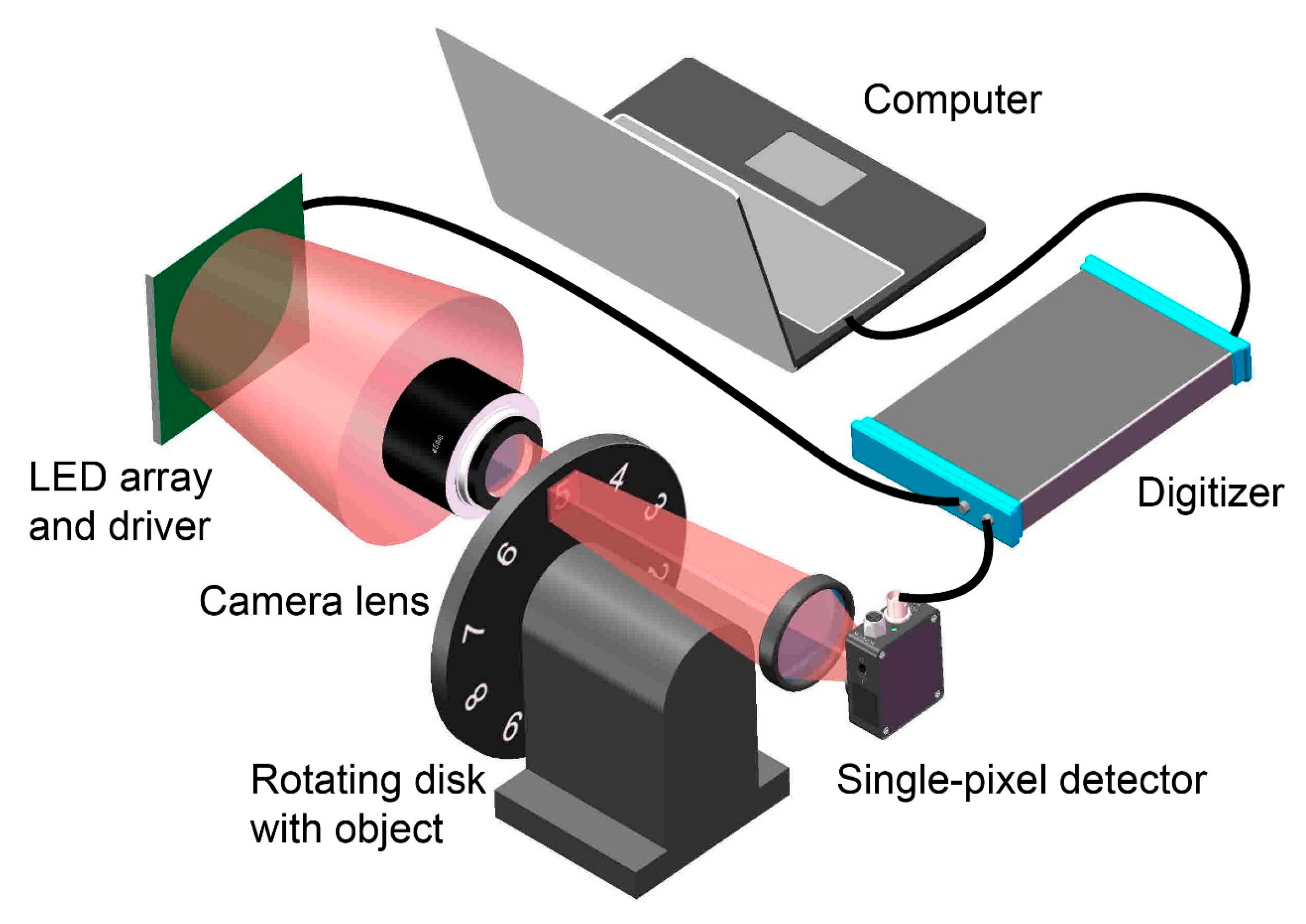
3.1. LED-Based Computational Ghost Imaging System
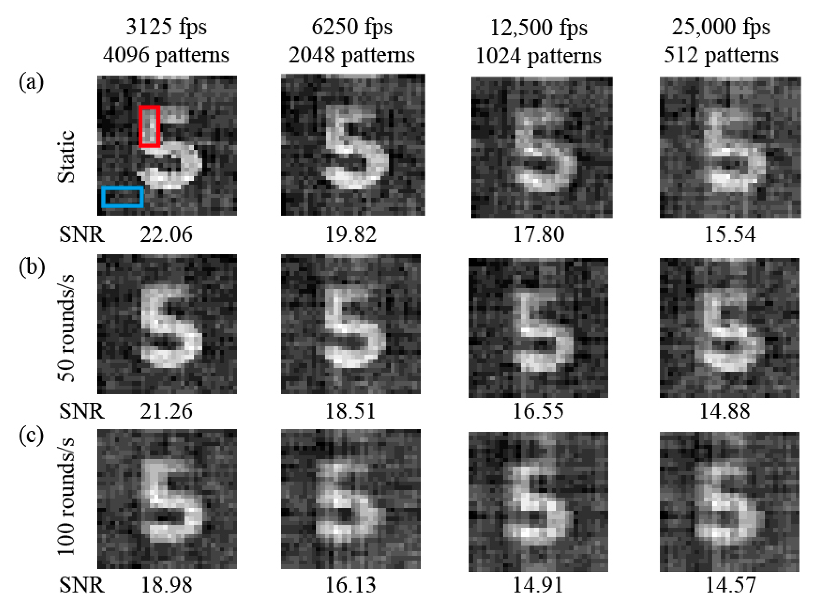
Our LED-based computational ghost imaging experimental set-up is shown in Figure 4. Our designed 32 × 32 pixel LED array with a size of 44 mm × 44 mm continuously displays a sequence of illuminating patterns. The driver board uses PMOS (Toshiba, Tokyo, Japan, SSM6P56FE) and NMOS (Toshiba, Tokyo, Japan, SSM6N56FE) as switching chips. A camera lens (JARAY, Liyang, China, f = 85 mm, F/1.4D) is used to image the LED array to a disk carved with ten numbers from 0 to 9, and the distance between the camera lens and the LED array is 270 mm. The size of the illumination area on the disk is 12 mm × 12 mm and can fully contain each number. The disk can rotate at a preset speed, and the maximum speed is 100 rounds per second. The transmitted light is focused on the detection surface of the single-pixel detector (Thorlabs, Newton, MA, USA, PDA10A(-EC), 150 MHz, 200 to 1100 nm, active area Ø1 mm) by a collecting lens (Thorlabs ACL50832U, f = 32 mm, NA = 0.76). The voltage signal from the single-pixel detector is recorded by a digitizer (Pico Technology, Cambridgeshire, UK, PicoScope 6404D, 2 GS/s) and is used for image reconstruction combined with the information of illuminating patterns.

3.2. Experiment

In our imaging experiment, the frequency of LED array display patterns reached 12.5 MHz, which is close to the theoretical limit of the single LED we used. To obtain a full sampling image with 32 × 32 pixel resolution, we needed to display 4096 illuminating patterns, and it took 0.32 ms . In order to obtain a faster imaging speed, we also used evolutionary compressed sensing to reduce the number of sampling patterns. In brief, the evolutionary compressed sensing method selects patterns with the maximum weight value of the previous full sample image as the illuminating patterns of the next frame. At the same time, we used the signal-to-noise ratio (SNR) to measure image quality. As shown in the first picture in Figure 5a, the pixel values in the red mark were used as the signal and the values in the blue marks were used as the background noise. As shown in Figure 5a, the compression rates of the last three static object images were 50%, 25% and 12.5%, and the respective time taken was 0.16, 0.08 and 0.04 ms . As the compression rate decreases, the quality of the image deteriorates due to the loss of information. However, in the acceptable image quality range, it is of great significance to improve the imaging speed through moderate compression. It is worth noting that we achieved 25,000 fps by using a compression rate of 12.5%, and the shape of the object in the digital images was still discernible. To verify the imaging speeds achieved by the system, we rotated the disk at 50 and 100 rounds/s as shown in Figure 5b,c; the imaging results for the full sample and three different compressive rate samples are shown. Due to the change in light intensity caused by the movement of the object while the LED array displayed each single illuminating pattern, the movement of the object degraded the imaging quality. However, even with the disk rotated at 100 rounds/s and the speed of the moved object at 25 m/s, the motion blur of the object was slight. It is important to note that our results only show raw images. In order to obtain better visual effects of images, we can adopt similar processing with traditional commercial cameras, such as an image processing method to remove background noise. Relevant experiments can be found in our previous work [28].

4. Conclusions

In this work, we have provided a scheme for the design of a 32 × 32 pixel LED illuminating module to make full use of the fast switching time of LEDs and to enable the illumination module to display patterns at 12.5 MHz frequency. The frame rate of imaging in the computational ghost imaging system reached 25,000 fps, which is one order larger than in our previous work. In terms of the frame rate of imaging, our computational ghost imaging system can reach the frame rate of common cameras in the market, whose maximum frame rate is approximately 1000 fps. Moreover, the feature of single pixel gives the computational ghost imaging system the advantages of anti-defocus, flexible design and high robustness compared with traditional cameras. Besides being used as an illumination module in the computational ghost imaging system, our designed high-speed LED illuminating module can be applied to other techniques, such as fringe 3D profiling and LIFI. As the fast-developing micro-LED has a faster switching speed, LED-based computational ghost imaging has the potential to achieve a faster imaging frame rate.

Author Contributions

Conceptualization, M.S. and L.L.; methodology, M.S.; software, H.H.; writing—original draft preparation, H.H. and Y.M.; writing—review and editing, H.H. All authors have read and agreed to the published version of the manuscript.

Funding

This research was funded by the National Natural Science Foundation of China (grant no. 61922011, grant no. U21B2034) and Open Research Projects of Zhejiang Lab (grant no. 2021MC0AB03).

Institutional Review Board Statement

Not applicable.

Informed Consent Statement

Not applicable.

Data Availability Statement

Not applicable.

Acknowledgments

The authors gratefully acknowledge the financial support of the National Natural Science Foundation of China and Open Research Projects of Zhejiang Lab.

Conflicts of Interest

The authors declare no conflict of interest. The funders had no role in the design of the study; in the collection, analyses, or interpretation of data; in the writing of the manuscript, or in the decision to publish the results.

References

  1. Bromberg, Y.; Katz, O.; Silberberg, Y. Ghost imaging with a single detector. Phys. Rev. A 2009, 79, 053840. [Google Scholar] [CrossRef] [Green Version]
  2. Shapiro, J.H. Computational ghost imaging. Phys. Rev. 2008, 78, 061802. [Google Scholar] [CrossRef]
  3. Zhao, C.; Gong, W.; Chen, M.; Li, E.; Han, A.S. Ghost imaging lidar via sparsity constraints. Appl. Phys. Lett. 2012, 101, 141123. [Google Scholar] [CrossRef] [Green Version]
  4. Gong, W.; Zhao, C.; Yu, H.; Chen, M.; Xu, W.; Han, S. Three-dimensional ghost imaging lidar via sparsity constraint. Sci. Rep. 2016, 6, 26133. [Google Scholar] [CrossRef] [Green Version]
  5. Yu, H.; Li, E.; Gong, W.; Han, S. Structured image reconstruction for three-dimensional ghost imaging lidar. Opt. Express 2015, 23, 14541–14551. [Google Scholar] [CrossRef]
  6. Wang, S.Y.; Li, L.J.; Chen, W.; Sun, M.J. Improving seeking precision by utilizing ghost imaging in a semi-active quadrant detection seeker. Chin. J. Aeronaut. 2021, 34, 171–176. [Google Scholar] [CrossRef]
  7. Sun, M.J.; Zhang, J.M. Single-pixel imaging and its application in three-dimensional reconstruction: A brief review. Sensors 2019, 19, 732. [Google Scholar] [CrossRef] [Green Version]
  8. Sun, B.; Edgar, M.P.; Bowman, R.; Vittert, L.E.; Welsh, S.; Bowman, A.; Padgett, M.J. 3D computational imaging with single-pixel detectors. Science 2013, 340, 844–847. [Google Scholar] [CrossRef] [Green Version]
  9. Sun, M.J.; Edgar, M.P.; Gibson, G.M.; Sun, B.; Radwell, N.; Lamb, R.; Padgett, M.J. Single-pixel three-dimensional imaging with time-based depth resolution. Nat. Commun. 2016, 7, 12010. [Google Scholar] [CrossRef]
  10. Hardy, N.D.; Shapiro, J.H. Computational ghost imaging versus imaging laser radar for three-dimensional imaging. Phys. Rev. A 2013, 87, 023820. [Google Scholar] [CrossRef]
  11. Chen, W.; Sun, M.J.; Deng, W.J.; Hu, H.X.; Li, L.J.; Zhang, X.J. Hyperspectral imaging via a multiplexing digital micromirror device. Opt. Lasers Eng. 2022, 151, 106889. [Google Scholar] [CrossRef]
  12. Radwell, N.; Mitchell, K.J.; Gibson, G.M.; Edgar, M.P.; Bowman, R.; Padgett, M.J. Single-pixel infrared and visible microscope. Optica 2014, 1, 285–289. [Google Scholar] [CrossRef]
  13. Bian, L.; Suo, J.; Situ, G.; Li, Z.; Fan, J.; Chen, F. Multispectral imaging using a single bucket detector. Sci. Rep. 2016, 6, 24752. [Google Scholar] [CrossRef] [PubMed] [Green Version]
  14. Jiang, W.J.; Li, X.Y.; Peng, X.L.; Sun, B.Q. Imaging high-speed moving targets with a single-pixel detector. Opt. Express 2020, 28, 7889–7897. [Google Scholar] [CrossRef]
  15. Phillips, D.B.; Sun, M.J.; Taylor, J.M.; Edgar, M.P.; Barnett, S.M.; Gibson, G.M.; Padgett, M.J. Adaptive foveated single-pixel imaging with dynamic super-sampling. Sci. Adv. 2017, 3, e1601782. [Google Scholar] [CrossRef] [PubMed] [Green Version]
  16. Chen, M.; Li, E.; Han, S. Application of multi-correlation-scale measurement matrices in ghost imaging via sparsity constraints. Appl. Opt. 2014, 53, 2924–2928. [Google Scholar] [CrossRef] [PubMed]
  17. Zhang, Z.; Ma, X.; Zhong, J. Single-pixel imaging by means of fourier spectrum acquisition. Nat. Commun. 2014, 6, 6225. [Google Scholar] [CrossRef] [Green Version]
  18. Li, L.J.; Chen, W.; Zhao, X.Y.; Sun, M.J. Fast Optical Phased Array Calibration Technique for Random Phase Modulation LiDAR. IEEE Photonics J. 2018, 1, 6900410. [Google Scholar] [CrossRef]
  19. Yusuke, K.; Kento, K.; Rui, T.; Yasuyuki, O.; Yoshiaki, N.; Takuo, T. Ghost imaging using a large-scale silicon photonic phased array chip. Opt. Express 2019, 27, 3817–3823. [Google Scholar]
  20. Qian, H.; Zhao, S.; Cai, S.Z.; Zhou, T. Digitally controlled micro-led array for linear visible light communication systems. IEEE Photonics J. 2017, 7, 1–8. [Google Scholar] [CrossRef]
  21. Lan, H.Y.; Tseng, I.C.; Lin, Y.H.; Lin, G.R.; Wu, C.H. High-speed integrated micro-leds array for visible light communication. Opt. Lett. 2020, 45, 2203–2206. [Google Scholar] [CrossRef] [PubMed]
  22. Duarte, M.F.; Davenport, M.A.; Takhar, D.; Laska, J.N.; Sun, T.; Kelly, K.F. Single-pixel imaging via compressive sampling. IEEE Signal Process. Mag. 2008, 25, 83–91. [Google Scholar] [CrossRef] [Green Version]
  23. Donoho, D.L. Compressed sensing. IEEE Trans. Inform. Theory 2006, 52, 1289–1306. [Google Scholar] [CrossRef]
  24. Katz, O.; Bromberg, Y.; Silberberg, Y. Compressive ghost imaging. Appl. Phys. Lett. 2009, 95, 131110. [Google Scholar] [CrossRef] [Green Version]
  25. Aβmann, M.; Bayer, M. Compressive adaptive computational ghost imaging. Sci. Rep. 2013, 3, 1545. [Google Scholar] [CrossRef]
  26. Sun, M.J.; Meng, L.T.; Edgar, M.P.; Padgett, M.J.; Radwell, N. A Russian Dolls ordering of the Hadamard basis for compressive single-pixel imaging. Sci. Rep. 2017, 7, 3464. [Google Scholar] [CrossRef] [Green Version]
  27. Pratt, W.K.; Kane, J.; Andrews, H.C. Hadamard transform image coding. Proc. IEEE 1969, 57, 58–68. [Google Scholar] [CrossRef] [Green Version]
  28. Xu, Z.H.; Chen, W.; Penulas, J.; Padgett, M.J.; Sun, M.J. 1000 fps computational ghost imaging using LED-based structured illumination. Opt. Express 2018, 26, 2427–2434. [Google Scholar] [CrossRef] [Green Version]
Figure 1. Simplified LED-based computational ghost imaging scheme.
Electronicmat 03 00009 g001
Figure 2. (a) Schematic diagram of the LED array design; (b) LED array display strategy.
Electronicmat 03 00009 g002
Figure 3. (a) Schematic diagram of the LED array driver design. Waveform diagrams for (b) the I/O signals, (c) the voltage drop of LED when RR = 40 Ω, RC = 200 Ω and (d) the light intensity of LED at four different states.
Electronicmat 03 00009 g003
Figure 4. The experimental LED-based computational ghost imaging system.
Electronicmat 03 00009 g004
Figure 5. The reconstructed images using the LED-based computational ghost imaging system. (a) Reconstructed images of the static object with different compression rates; (b) reconstructed images of the rotating object at 50 rounds/s; (c) reconstructed images of the rotating object at 100 rounds/s.
Electronicmat 03 00009 g005
Publisher’s Note: MDPI stays neutral with regard to jurisdictional claims in published maps and institutional affiliations.

