1. Introduction
The construction industry is currently experiencing a significant transformation driven by the urgent necessity to reduce greenhouse gas emissions and embrace circular economy principles. In this context, geosourced and biosourced materials are gaining recognition as credible alternatives to traditional construction materials like concrete and fired bricks, which are known for their high energy consumption and substantial CO
2 emissions during production. Among these sustainable options, unfired earth stands out due to its abundance, low embodied energy, local availability, and minimal processing requirements. Used for nearly 10,000 years [
1,
2], unfired earth remains one of the oldest and most widespread vernacular building materials. Today, approximately 8 to 10% of the global population—up to 25% in some developing countries—reside in earth-based dwellings [
3]. Although its popularity waned during the twentieth century with the rise in industrialized concrete construction, recent renewed interest from scientific and technical perspectives has been spurred by decarbonization goals and the increasing integration of circular economy strategies within the construction sector [
4,
5,
6].
Unfired earth can be applied through a variety of construction techniques tailored to local geography, climate, and cultural practices. Common load-bearing methods include adobe, rammed earth, and cob construction. Rammed earth involves compacting moist soil within formwork to create dense, monolithic walls with high thermal mass and adequate compressive strength [
7]. Adobe bricks are produced by mixing clay-rich soil with water, then air-drying before use [
8]. Another popular technique involves compressed earth blocks (CEBs), made through mechanical compaction, which typically offers better uniformity and controlled mechanical properties. In their unstabilized form—without hydraulic binders or chemical additives—unfired earth bricks are highly environmentally friendly and fully recyclable. However, their sensitivity to water and relatively modest mechanical strength necessitate careful consideration during design and construction [
9,
10].
From a mechanical standpoint, adobe-like earth bricks typically exhibit compressive strengths ranging from 0.6 to 8.3 MPa [
11,
12,
13,
14,
15]; however, some recent experimental results have shown a narrower range of 1.03 to 4.80 MPa [
6]. While these values are lower than those of conventional concrete, they can be sufficient for load-bearing applications when paired with appropriate structural solutions, such as increased wall thicknesses of around 30 cm and optimized masonry bonding techniques [
16].
Beyond structural performance, the thermal properties of unfired earth are crucial in designing energy-efficient buildings. Thanks to their high density and specific heat capacity, earth materials provide significant thermal inertia, helping to dampen indoor temperature fluctuations. Incorporating plant fibers, like straw, can further reduce thermal conductivity and improve insulation, though this often comes at the expense of mechanical strength.
Generally, unfired earth shows a high heat storage capacity and moderate thermal diffusivity, making it effective at moderating temperature swings within buildings [
17]. However, its thermal conductivity—typically between 0.5 and 1.2 W·m
−1·K
−1 [
18,
19], remains well above the threshold for high-performance insulation materials, which usually have a thermal conductivity below 0.03 W·m
−1·K
−1 [
20]. Consequently, while unfired earth excels at heat storage, it offers limited insulation, posing a significant scientific challenge: how to enhance its thermal performance without compromising its mechanical and environmental benefits.
One promising avenue of research involves integrating phase change materials (PCMs). These materials can absorb and release thermal energy during phase transitions from solid to liquid and vice versa, thereby increasing the thermal inertia of building envelopes and reducing indoor temperature fluctuations.
The effectiveness of a phase change material (PCM) is strongly governed by its phase transition temperature, which should match the indoor thermal comfort range to maximize latent heat storage and release. For residential buildings, the optimal PCM melting temperature is generally reported to lie between 22 and 28 °C, corresponding to typical indoor comfort conditions [
21,
22,
23].
Among bio-based PCMs, coconut oil has attracted considerable attention because its melting temperature, typically ranging from 22 to 27 °C, falls within this optimal comfort range. In addition, coconut oil exhibits good thermal stability, low supercooling, and a latent heat of fusion suitable for passive thermal energy storage applications in buildings, making it a promising candidate for indoor temperature regulation [
24].
However, incorporating coconut oil into construction materials requires an effective containment method to prevent leakage during phase changes. Encapsulation within polylactic acid (PLA), a biodegradable and biosourced polymer, offers a practical solution that balances durability, environmental friendliness, and mechanical stability [
25,
26].
In this context, while conventional literature predominantly focuses on high-embodied-carbon building materials, the novelty and originality of this study lie in its shift toward an entirely eco-friendly system. The current work explores heat transfer mechanisms within an innovative composite combining unfired earth, PLA encapsulation, and coconut oil as a biosourced phase change material (PCM), with a particular focus on thermal conduction and the processes of latent heat storage and release. The aim is to evaluate how thermophysical properties influence heat transfer across the brick’s thickness and to assess the potential of PCMs to boost the thermal performance of unfired earth. Special attention is given to analyzing thermal phase shifts, the attenuation of temperature peaks, and the capacity for thermal energy storage. Ultimately, this research seeks to identify optimal configurations for integrating PCMs into unfired earth materials, enhancing their use in high thermal inertia building envelopes. More broadly, it contributes to the advancement of sustainable construction solutions by exploring the synergistic potential of geosourced materials and passive thermal energy storage technologies.
2. Materials and Methods
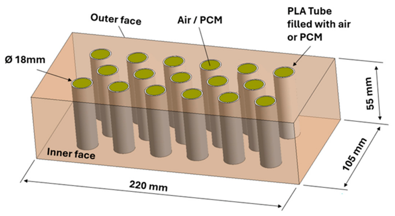
The geometry studied is representative of a standard perforated fired brick measuring 220 × 105 m × 55 mm, featuring 17 cylindrical cavities of 18 mm diameter distributed across three rows (
Figure 1). This type of commercial fired brick is widely used in the construction sector, both as an interior or exterior wall cladding and as a structural element, load-bearing wall, column casing, or jamb, owing to its good mechanical properties and relatively low weight.
In the present study, brick is made of unfired earth, a natural and ecological building material whose thermal properties are particularly well-suited to the passive regulation of thermal comfort in buildings. The material selected is unfired earth, whose thermophysical properties were characterized in a previous study [
17]. The cylindrical cavities are filled either with air or with a phase change material (PCM), whose integration aims to exploit the latent heat of fusion to attenuate daily thermal fluctuations within the wall. Coconut oil was selected as the PCM on account of its melting temperature (
) falling within the thermal comfort range (20–24 °C in winter/23–26 °C in summer [
27]) and its availability as a biosourced material.
The main thermophysical and mechanical properties of the raw earth used to make the bricks are summarized in
Table 1 [
17]. The material properties are derived from analyses conducted on adobe samples collected from demolition and renovation sites of old homes and barns [
17]. The raw earth under consideration has a dry density of 1693 kg/m
3. From a hygrothermal perspective, its thermal conductivity of 0.799 W/(m·K) (±0.054) is relatively low. Its thermal diffusivity of 0.479 × 10
−6 m
2/s and its specific heat capacity of 0.969 kJ/(kg·K) indicate a notable ability to store and slowly release heat, thereby promoting the thermal inertia of the wall and helping to mitigate temperature fluctuations within the building.
2.1. Phase Change Material
Refined coconut oil was selected as a phase change material (PCM) because its transition temperature ranges from 22 to 27 °C [
24], making it suitable for thermal management applications in buildings. The thermophysical properties of refined coconut oil used in this study are taken from the study by Kahwaji & White [
28], who performed DSC measurements and determined coconut oil’s heat capacity and thermal conductivity as functions of temperature.
A density of 920 kg·m
−3 was adopted for coconut oil, consistent with values reported in the literature generally ranging from 920 to 925 kg·m
−3 depending on temperature and composition [
29].
The main thermophysical characteristics of refined coconut oil are summarized in
Table 2. These thermophysical properties, as well as those of air, are dynamically implemented within a custom User-Defined Function (UDF) compiled in Ansys Fluent.
2.2. PCM Encapsulation
To ensure the containment of the PCM in its liquid state and the durability of the composite, coconut oil is encapsulated in tubes printed from polylactic acid (PLA), a biodegradable, bio-based polymer [
30]. The tubes, manufactured via 3D printing, have a wall thickness of 1 mm. The thermophysical properties of the PLA used in this study are (see
Table 3): a density of 1250 kg·m
−3, a thermal conductivity of 0.13 W·m
−1·K
−1 close to that of the coconut oil, and a specific heat capacity of 1.8 kJ·kg
−1·K
−1 [
30]. To counteract the porosity issues inherent to 3D-printed PLA, beeswax can be heated to a liquid state and brushed onto the inner walls of the tube, correcting these micro-defects to ensure a tight seal.
2.3. Specific Experimental Protocol to Qualify the PCM Behavior
In order to characterize the thermal behavior of the PCM and to provide reference data for numerical model validation, experimental tests were conducted under controlled thermal loading.
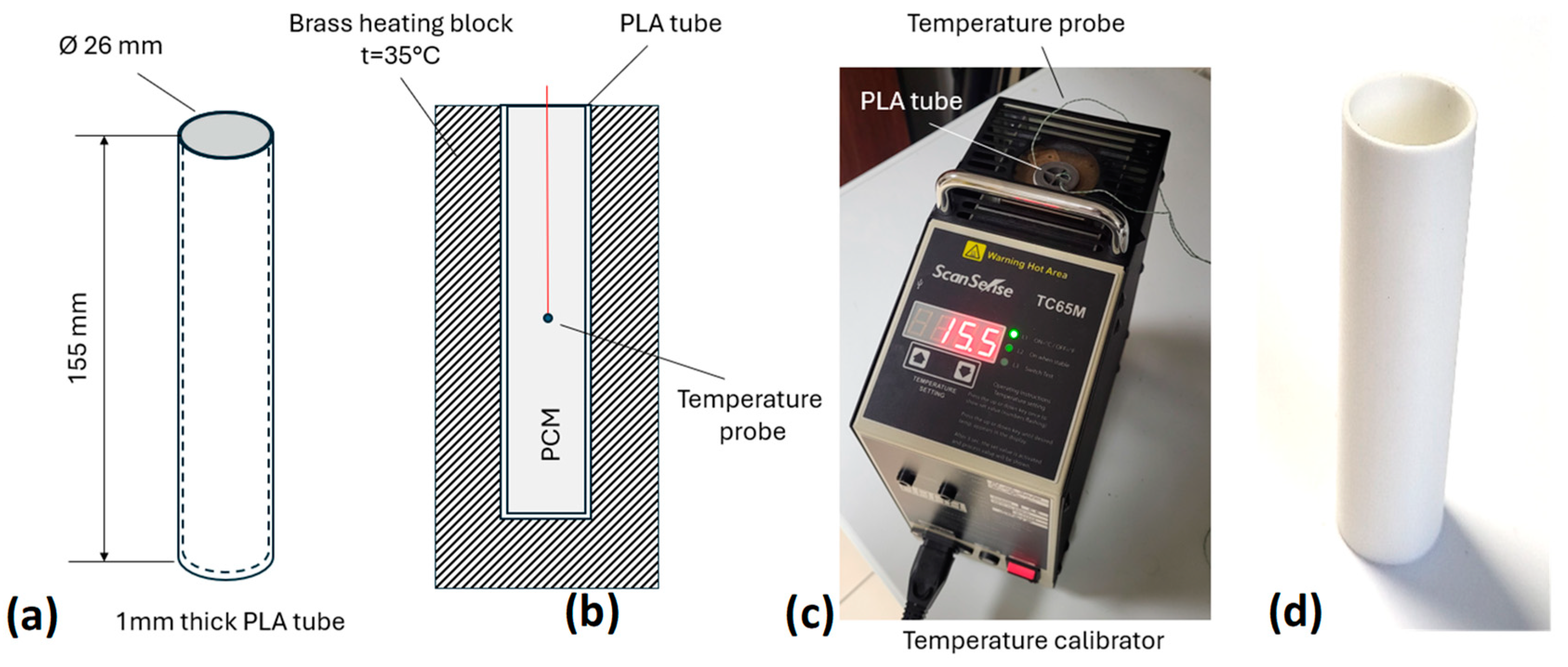
Figure 2 illustrates the equipment used. Coconut oil, previously brought to a liquid state, was introduced into a 1 mm thick PLA tube with an inner diameter of 24 mm. This tube was then inserted into the well of a ScanSense TC65M calibration furnace, which consists of a brass heating block whose inner diameter perfectly matches the outer diameter of 26 mm of the tube. The applied thermal cycle consisted of imposing a temperature of 35 °C; once this target was reached, the furnace was turned off to initiate the cooling phase. The temperature evolution of the PCM was measured continuously using a K-type thermocouple positioned at mid-height of the tube, while a second thermocouple was placed at the brass/PLA interface to monitor the temperature imposed by the heating block.
2.4. Numerical Methods
2.4.1. Problem Definition and Computational Setup
For the purposes of the numerical study, a computer-aided design (CAD) model was developed by faithfully reproducing the geometric characteristics of a commercial standard-sized perforated brick (220 × 105 × 55 mm3) featuring 17 cylindrical cavities. The detailed dimensions were strictly followed to ensure a realistic representation of the coupled heat transfer phenomena between the solid raw earth matrix, the PLA containers, and the phase change material (PCM), the latter being modeled as a liquid in the simulations.
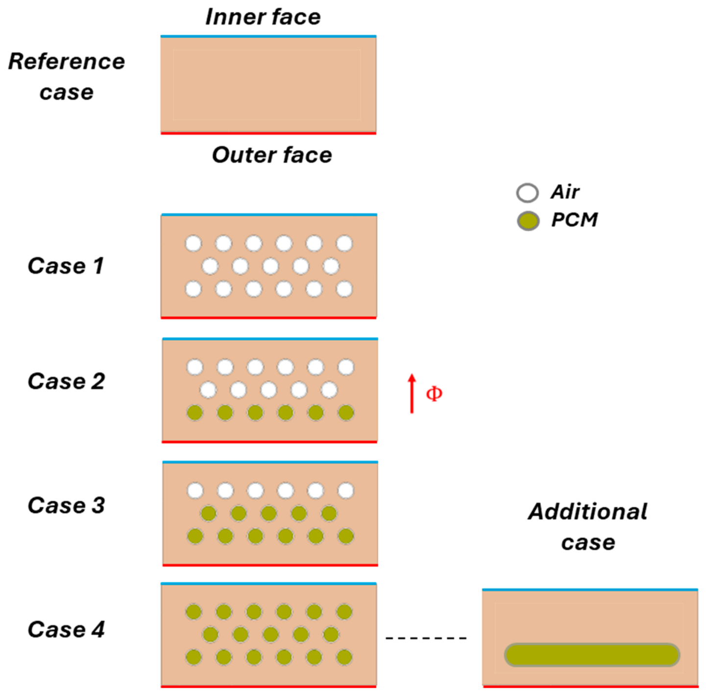
Figure 3 presents the numerical protocol implemented to evaluate thermal storage efficiency and the influence of the number of PCM rows on the thermal and energy response of the brick. The study compares a reference solid brick with four configurations incorporating an increasing number of PCM-filled rows: Case 1, containing no PCM and three air-filled rows; Case 2, containing one PCM-filled row; Case 3, containing two PCM-filled rows; and Case 4, containing three PCM-filled rows.
In order to further analyze thermal inertia and explore a solution better suited for potential industrialization, the 17 individual tubes, each with a capacity of 11 mL, were subsequently replaced by a single container of equivalent volume, namely 187 mL. This container has a length of 169 mm, a width of 19 mm, and a height of 59 mm, with both lateral faces featuring a rounded edge with a radius of 0.01 m. To optimize the compromise between thermal performance and mechanical integrity, this container was positioned near the exterior face subjected to the thermal loading, while maintaining sufficient distance to avoid compromising the structural strength of the brick. More specifically, the equivalent PCM container was positioned at approximately one-third of the brick thickness from the heated face.
This location was selected to promote an early activation of the PCM while avoiding excessively rapid melting at the beginning of the thermal cycle. Such a positioning is consistent with the findings of Gao et al. [
31], who demonstrated that the thermal performance of PCM-integrated walls is highly dependent on the location of the PCM layer and that positioning the PCM near the heat-exposed side generally provides a better compromise between latent heat utilization and thermal attenuation.
2.4.2. Physical Model and Governing Equations
The simulations were performed using the ANSYS Fluent
® 2026R1 computational code, which is based on the finite volume method. Heat transfer is modeled in a transient regime using the general energy conservation equation. In Fluent, the temperature field is obtained from the following equation:
where
is the density of the material (kg·m−3),
is the specific heat capacity (J·kg−1·K−1),
is the thermal conductivity (W·m−1·K−1),
is a source term associated with heat release or absorption (W·m−3).
The thermal behavior of the phase change material (PCM) is described using the enthalpy-based solidification/melting model available in ANSYS Fluent. Within this formulation, the source term
represents the latent heat exchange associated with the phase transition and is given by:
where
is the PCM density,
is the latent heat of fusion, and
is the liquid fraction. During melting, this term represents the absorption of thermal energy, whereas during solidification it represents the release of latent heat. In the present work, this source term is automatically handled through the enthalpy-porosity method implemented in ANSYS Fluent.
The total enthalpy
is defined by:
with
is the enthalpy at the reference temperature ,
is the latent heat of fusion (J·kg−1),
is the liquid fraction (ranging from 0 to 1).
The evolution of the liquid fraction is described by a linear relationship as a function of temperature:
where
and
are the temperatures at the onset and completion of melting, respectively.
The energy equation then becomes:
The solution of this equation makes it possible to simultaneously track the variation in temperature and the progression of the liquid phase over time. The conduction term is treated using the local thermal conductivity of the material (brick or PCM). Interfaces between materials are handled automatically by Fluent using continuity conditions for temperature and heat flux.
To ensure an accurate representation of the thermal behavior of the materials constituting the brick, a specific database was created within the CFD code. The thermophysical properties of the raw earth and PLA, considered constant over the studied temperature range, were directly incorporated into this database using values obtained experimentally or from the literature.
In contrast, coconut oil, as a phase change material, exhibits thermophysical properties that strongly depend on temperature, particularly near its melting range. To account for this variability, user-defined functions (UDFs) were developed and implemented in the solver. These UDFs describe the temperature-dependent evolution of five key PCM properties: specific heat capacity, thermal conductivity, enthalpy, density, and dynamic viscosity. This approach enables accurate capture of the melting and solidification phenomena of coconut oil during the thermal cycle, especially the discontinuity in properties associated with the phase change.
2.4.3. Computational Domain and Mesh
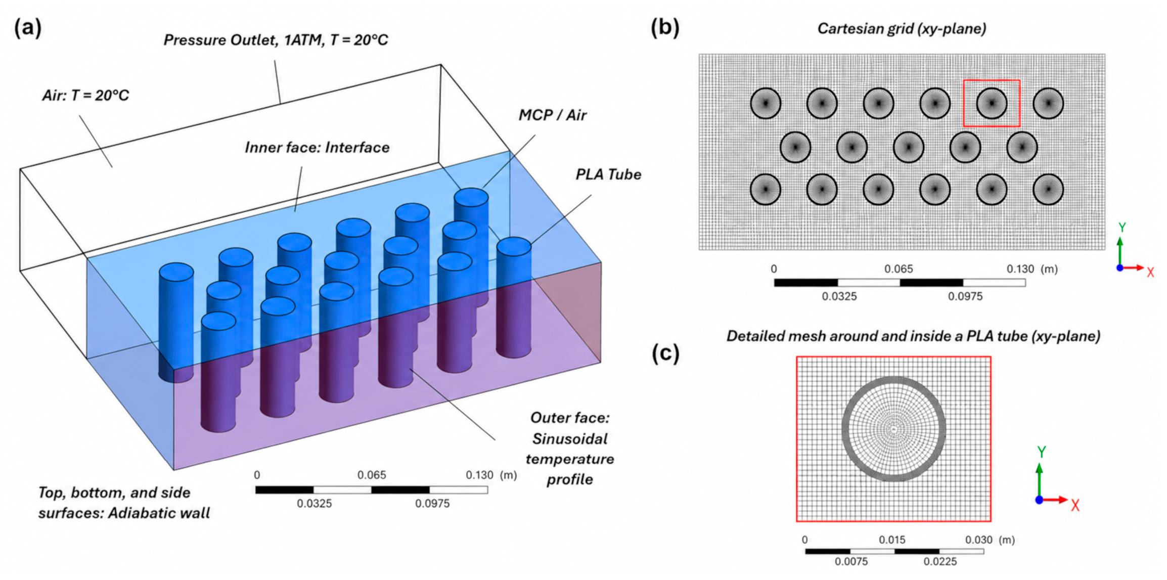
The computational domain was discretized using a hybrid tetrahedral–hexahedral mesh of approximately 1.2 million elements, with local refinement at the brick/PCM interfaces and exposed surfaces, as shown in
Figure 4.
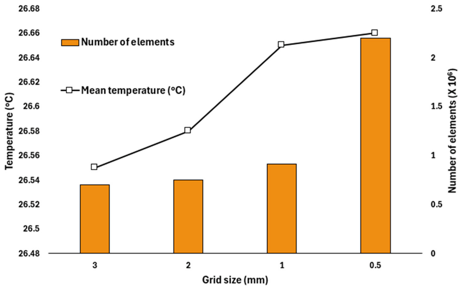
To verify the numerical accuracy of the CFD model, a mesh independence analysis was conducted using four different mesh resolutions for the configuration with three air-filled rows (
Figure 5). A constant temperature of 50 °C was applied to the outer surface of the brick under steady-state conditions, and the resulting temperature on the inner surface was monitored. The sensitivity of the solution to mesh refinement was evaluated based on the average temperature of the inner face. The results show that a mesh size of 1 mm provides a satisfactory balance between accuracy and computational efficiency. Additional refinement resulted in a temperature variation of less than 0.01 °C, despite a significant increase in the number of mesh elements and computational requirements.
2.4.4. Boundary Conditions
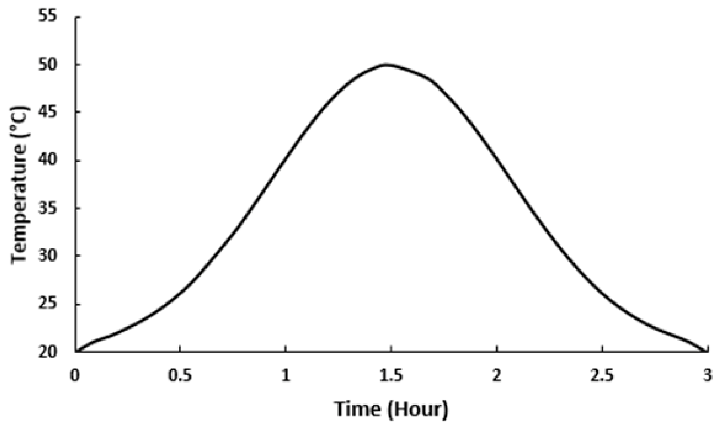
The temperature of the outer face of the brick (
Figure 6) is imposed using a user-defined function (UDF) that reproduces the variation in the external temperature of the brick according to a diurnal cycle. It is worth noting that the maximum temperature value of 50 °C is consistent with temperatures measured on building surfaces exposed to significant solar radiation during the summer period.
Table 4 summarizes the boundary conditions of the problem.
Thermal radiation between the internal cavity surfaces and the brick walls was neglected in the present numerical model. This assumption is considered acceptable because the imposed boundary conditions describe heat transfer mainly through conduction and convection mechanisms, while radiative effects remain of secondary importance under moderate temperature differences [
32,
33].
2.4.5. Numerical Parameters and Solutions
The simulations are carried out over a total duration of 10,800 s (3 h), which represents a time-compressed version of the 24 h diurnal cycle. This reduction in simulated time effectively limits the computational cost while preserving the representativeness of the physical phenomena under study, since the temperature variation imposed on the outer wall accurately reproduces the daily thermal dynamics experienced by the brick.
A time step of 5 s was selected as a satisfactory compromise between temporal resolution accuracy, fine enough to capture the dynamics of heat transfer within the brick and the cavities, and the computational cost associated with simulating the full cycle. The equations are discretized using second-order schemes, and pressure–velocity coupling is ensured by the SIMPLE algorithm.
The convergence criteria are set to 10−6 for energy and 10−4 for the other equations. The computations were performed on a multiprocessor workstation (Dell Precision 7920, 24 cores, 3.2 GHz, 384 GB RAM), with one full cycle requiring approximately 10 h of computation time.
2.4.6. Validation of the Numerical Model from Experimental Data
The objective of this study is to simulate heat transfer in a hollow adobe brick whose 17 cylindrical cavities are filled with either air or a phase change material (PCM), specifically coconut oil. To validate the numerical method, we assessed the ability of the model to reproduce the behavior of a phase change material subjected to a thermal cycle. To generate the reference experimental data, a calibration furnace was used to ensure uniform heating of the walls of a PLA tube filled with coconut oil. This setup, detailed in
Figure 2, made it possible to measure in real time the temperature evolution at the core of the PCM as well as the thermal kinetics imposed by the cycle.
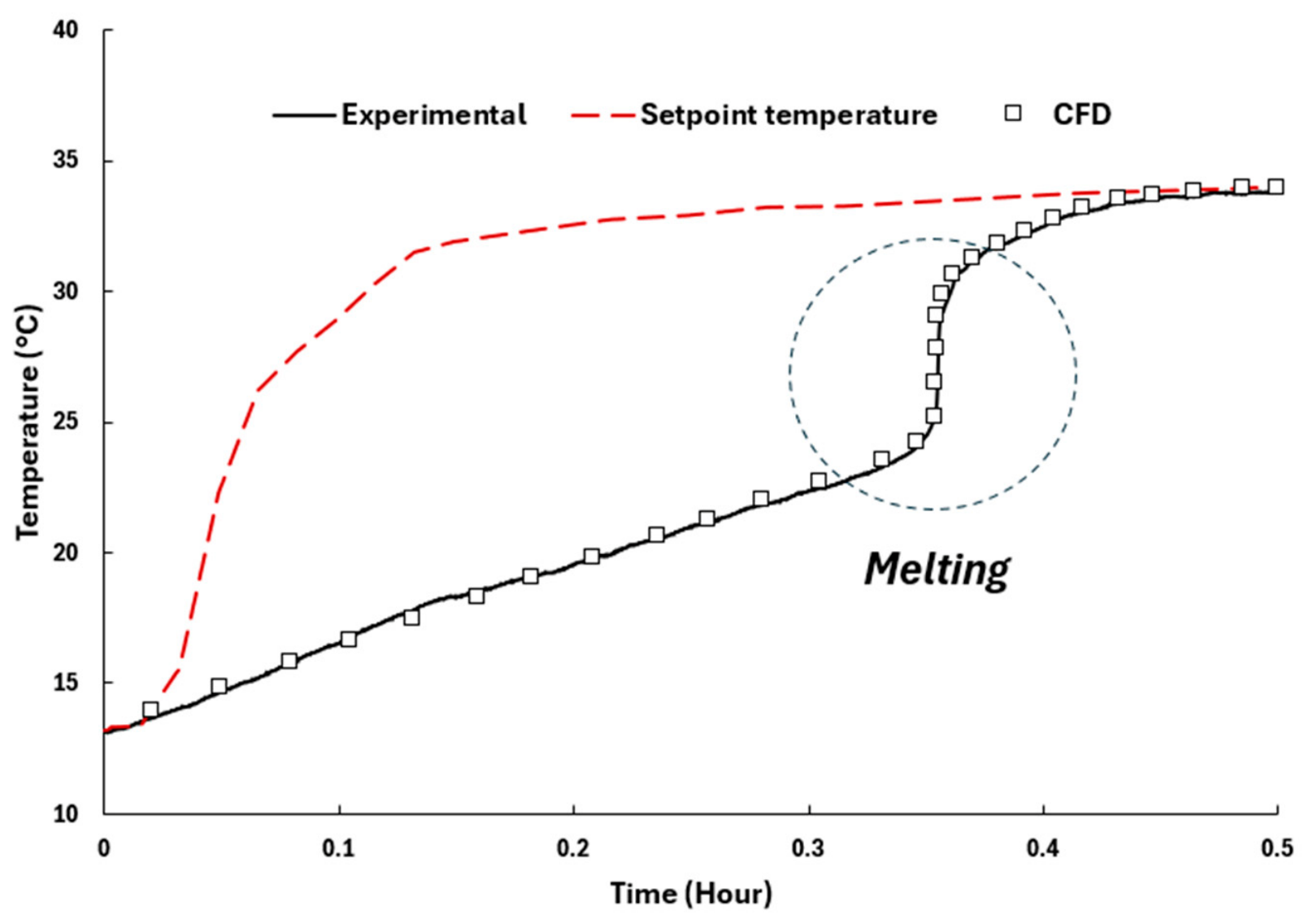
Figure 7 presents a comparison between the results obtained from the numerical simulation (CFD) and the experimental measurements for this uniform heating. The red dashed curve represents the evolution of the furnace chamber temperature (setpoint temperature) during the heating process. A rapid temperature increase is observed during the first few minutes, reaching approximately 32 °C within about 10 min, followed by a slower rise toward the final setpoint of nearly 34 °C. This heating profile imposes a transient thermal excitation on the PCM sample. In contrast, the temperature of the coconut oil-based PCM exhibits a delayed response due to its thermal inertia. During the initial heating stage, the temperature increases progressively and almost linearly from the initial temperature up to approximately 24 °C, corresponding to the onset of melting. This stage reflects sensible heat storage in the solid phase. A marked change in the thermal response is then observed in the temperature range associated with phase transition. Around the melting temperature, the experimental curve exhibits a characteristic slope break followed by a sharp temperature increase, indicating the progressive solid–liquid transformation of coconut oil. This behavior results from the latent heat absorption process, during which thermal energy is primarily used for phase change rather than for increasing temperature. Once the melting process is nearly complete, the temperature rises rapidly and asymptotically approaches the furnace setpoint.
The CFD predictions reproduce this transient thermal behavior with very good accuracy over the entire heating period. In particular, the numerical results accurately capture the three main stages of the thermal response: (i) sensible heating in the solid phase, (ii) the phase transition region around 24 °C, and (iii) post-melting heating in the liquid phase. The sharp temperature rise observed experimentally during the melting interval is also well predicted, demonstrating that the model correctly reproduces the latent heat effects and the associated non-linear thermal dynamics. The slight deviations observed in the transition region may be attributed to simplifications in the numerical assumptions, such as the idealized thermophysical properties or the treatment of phase transition over a narrow melting range. Nevertheless, the overall agreement between experimental measurements and CFD results remains excellent, confirming the suitability of Fluent’s enthalpy–porosity formulation along with custom User-Defined Functions (UDF) for modeling the melting behavior of coconut oil.
This validation reveals that the CFD model is able to reliably reproduce transient heat transfer and phase change phenomena in the PCM. It therefore provides a robust basis for subsequent numerical investigations of the thermal performance of earth-based bricks incorporating coconut oil phase change materials.
3. Results and Discussion
3.1. Numerical Results
3.1.1. Impact of the Number of MCP Layers on Thermal Stability
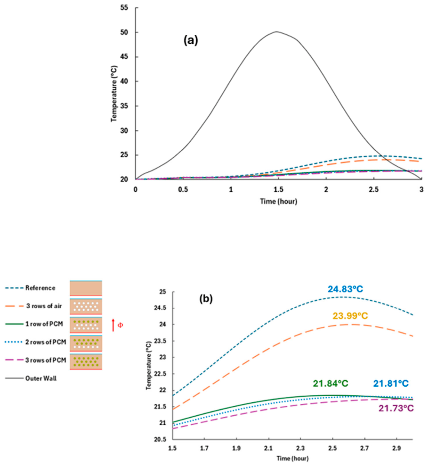
Figure 8 presents the evolution of the temperature on the inner face of the brick together with the variation in the external temperature. The results clearly demonstrate the influence of the number of PCM layers on the thermal regulation performance of a wall subjected to daily temperature fluctuations.
In the reference configuration (full brick), the inner-face temperature follows the trend of the outer face with a distinct phase shift, reaching a maximum of approximately 24.8 °C after about 2 h 30 min. This behavior reflects significant heat transfer through the wall and highlights the thermal inertia limitations of the baseline raw earth brick. Compared to the full brick, the addition of three rows of air-filled cylindrical cavities induces a noticeable thermal damping effect, dropping the maximum temperature to 23.99 °C, which represents a reduction of more than 0.8 °C in peak temperature. This is primarily driven by the thermal conductivity of air (~0.02 W·m−1·K−1), which is substantially lower than that of raw earth (0.799 W·m−1·K−1). The integration of a single PCM layer further reduces the thermal amplitude (Tmax ≈ 21.84 °C), with a slight additional improvement when using two layers (Tmax ≈ 21.81 °C). The optimum is achieved with three layers (Tmax ≈ 21.73 °C). These results demonstrate that a higher number of PCM rows progressively enhances the latent heat storage capacity of the system.
These results are consistent with numerous studies in the literature that have demonstrated that incorporating PCMs into building walls affects thermal inertia and reduces the amplitude of indoor temperature fluctuations [
31,
34]. The multilayer configuration appears to be a particularly effective strategy for maximizing latent heat storage without saturation, in agreement with previous works focusing on optimizing the number of PCM layers in composite wall systems [
35,
36].
3.1.2. Spatial Distribution of Thermal Attenuation According to Layer Position
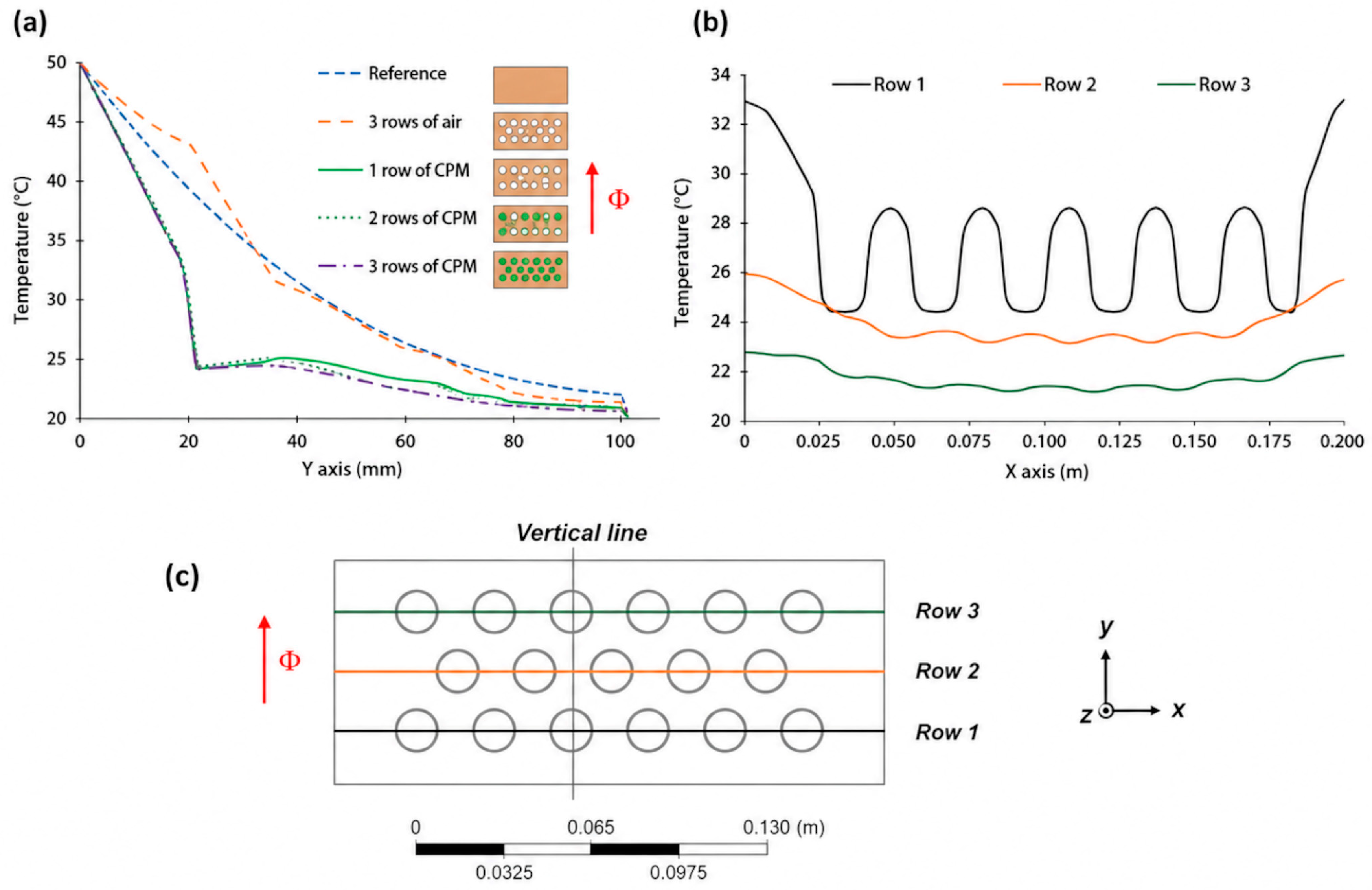
Figure 9 shows the temperature profiles plotted through the thickness of the brick along the vertical
y-axis (left graph), as well as the profiles plotted along the horizontal
x-axis across the three rows of cavities for the three-row PCM configuration (right graph).
In the vertical profile, all configurations exhibit a monotonic decrease in temperature from the outer face (50 °C) to the inner face (~20 °C), with the shape and slope directly governed by the thermal conductivity of the materials involved. The full brick (reference case), composed solely of raw earth (λ = 0.799 W/m·K), shows the most uniform gradient and the highest inner surface temperature, indicating an uninterrupted conductive heat transfer through the wall. The configuration with three rows of air cavities exhibits higher thermal resistance than the reference case, since air is a very poor conductor. This results in a steeper temperature profile within the earth regions and a more pronounced drop across the cavities.
The PCM-based configurations show a distinctive behavior: a clear temperature plateau appears around 24–25 °C within the cavity zones, which is characteristic of the phase change process of coconut oil, whose melting temperature is 24.5 °C. This plateau results from the absorption of latent heat by the PCM, which maintains an almost constant temperature locally until the phase transition is complete.
The slight temperature fluctuations observed in the horizontal profile (right graph) reflect the alternation of materials along the path: peaks correspond to raw earth zones (λ = 0.799 W/m·K, conductive), while troughs correspond to PLA tubes (λ = 0.13 W/m·K) and PCM (λ = 0.19 W/m·K in solid state, 0.17 W/m·K in liquid state), both considerably less conductive.
The analysis by row reveals that Row 1, located closest to the hot outer surface, is the most actively engaged layer: its temperature fluctuates significantly around the melting temperature (23.8 °C), indicating that the coconut oil is actively undergoing phase change and absorbing latent heat. In contrast, Row 2 and Row 3, further from the heat source and protected by Row 1 and the intervening earth layer, exhibit markedly lower temperatures and much smaller fluctuations. This suggests that the PCM in these deeper layers remains mostly in the solid state and is therefore much less thermally activated.
These results highlight that the effectiveness of PCM strongly depends on its position within the wall thickness and its proximity to the heat source.
3.2. Thermal Performance Metrics
The thermal behavior of the modified bricks was evaluated in terms of reduction in maximum inner surface temperature, temperature fluctuations, and thermal phase shift.
The damping of temperature fluctuations, commonly referred to as the decrement factor (DF), indicates the ability of the bricks to attenuate temperature variations by considering the maximum and minimum values of both the inner and outer surfaces, according to Equation (6) [
37]:
where
and
refer to the maximum and minimum temperatures on the inner surface of the test bricks over the entire thermal cycle. Similarly,
and
represent the maximum and minimum temperatures on the outer surface of the test bricks (in °C).
A decrement factor value close to zero indicates excellent thermal damping capacity, reflecting a strong attenuation of temperature fluctuations between the outer and inner surfaces of the wall. In the present study, for an extreme external temperature oscillation of 30 °C, the results summarized in
Table 5 clearly show that increasing the number of PCM layers leads to a progressive and significant reduction in the amplitude of thermal fluctuations. The decrement factor decreases from 0.247 for the reference configuration to 0.088 for the three-layer configuration. This reduction highlights the effectiveness of coconut oil in storing heat through phase change, thereby contributing to stabilizing the indoor temperature.
These results are in excellent agreement with the work of Mahdaoui et al. [
38], who showed that a hollow brick impregnated with PCM enables a significant stabilization of the inner surface temperature and a substantial reduction in the decrement factor. Similarly, recent studies on earth-based walls incorporating PCMs report a significant reduction in daily thermal amplitude due to increased latent thermal inertia [
39].
3.2.1. Time Lag
The phase shift in the peak temperature, commonly referred to as the time lag, is another parameter to be evaluated, accounting for the time difference at which the peak temperature is reached on the inner and outer surfaces of the bricks [
37]. Mathematically, the time lag was calculated using Equation (7), where
denotes the time at which the maximum temperature occurs on the inner surface, while
is the time at which the maximum temperature occurs on the outer surface of the bricks (in minutes).
The analysis of
Table 6 highlights significant differences between the studied configurations in terms of time lag. The full brick, used as a reference, shows a time lag of approximately 1 h 03 min, with a peak internal surface temperature reached at 2 h 33 min. This result serves as the reference baseline from which the contribution of the cavities, whether filled with air or PCM, is evaluated.
The configuration with three rows of air slightly improves the time lag (+3 min compared to the reference), bringing the time lag to approximately 1 h 06 min. Although air is a poor thermal conductor, its limited phase-shifting effect is explained by the absence of latent heat energy storage: air can only delay heat transfer through conductive resistance, without any active storage mechanism.
The configurations incorporating PCM exhibit contrasting behaviors depending on the number of rows used. The configuration with a single PCM row paradoxically shows a slightly lower time lag than the reference (–3 min). The configuration with two PCM rows considerably improves time lag (+9 min), reaching a time lag of approximately 1 h 12 min, thanks to a greater amount of PCM available to absorb latent heat. However, it is the configuration with three PCM rows that proves to be the most effective, with a time lag of 1 h 30 min and a gain of +27 min compared to the reference, an improvement of nearly 43%. This result is explained by the successive activation of the three PCM-filled cavity rows, which act as active thermal barriers absorbing the latent heat of fusion of coconut oil (23.8 °C) and effectively delaying the propagation of the thermal wave toward the inner face.
These results confirm that increasing the volume of PCM within the brick is an effective lever for improving the thermal phase shift of the wall, with an almost proportional relationship between the number of PCM rows and the gain in time lag. This trend is consistent with the literature [
34], illustrating how latent heat delays the propagation of the thermal wave.
3.2.2. Spatio-Temporal Analysis of the Thermal Gradient
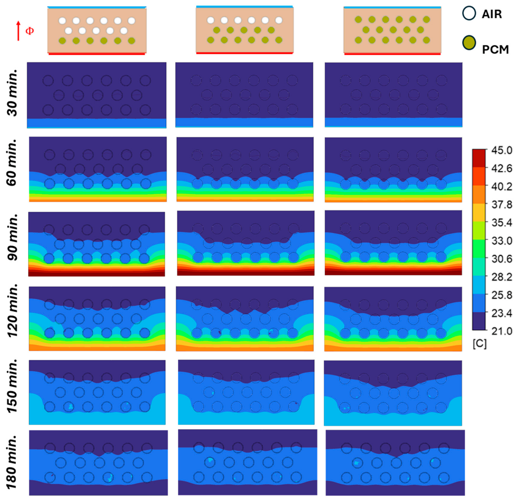
Figure 10 and
Figure 11 highlight the spatio-temporal evolution of the temperature field across the thickness of the brick for the different configurations studied. The analysis of this thermal distribution must be interpreted in light of the thermophysical properties of the materials making up the multilayer system, namely raw earth, PLA, and the phase change material (coconut oil). With regard to heat transfer within the internal cavities, their small dimensions (diameter = 16 mm and height = 55 mm) promote a strong confinement effect that substantially suppresses buoyancy-driven flow. Consequently, natural convection is expected to be very limited, and conductive heat transfer becomes the dominant heat transfer mechanism within the cavities. For the air rows, it is well-established in building physics that enclosed cavities with a characteristic dimension smaller than 15 to 20 mm experience dominant viscous forces that completely overcome buoyancy forces, keeping the Rayleigh number well below the critical threshold required to trigger convective loops, thus behaving as ‘captive air’. Similarly, for the PCM rows, when the material melts into its liquid phase, the narrow 16 mm diameter combined with fluid friction against the PLA tube walls stifles any macroscopic convective motion under standard building temperature gradients. Consequently, the asymmetry observed in the thermal profiles and enthalpy fields of
Figure 10 and
Figure 11 does not stem from internal convective currents, but is entirely the result of a conduction-driven thermal gradient across the cylinders, induced by the unidirectional heat flux originating exclusively from the external face of the brick.
In the case of the full brick (
Figure 10), the propagation of the heat front appears relatively fast and continuous between the external and internal faces. This behavior is explained by the relatively high thermal conductivity of the brick, equal to 0.799 W/m·K, associated with a thermal diffusivity of 0.479 × 10
−6 m
2/s. This diffusivity, which reflects the rate at which a thermal disturbance propagates through the material, promotes relatively efficient heat wave transmission across the mineral matrix. The specific heat capacity of 0.969 kJ/(kg·K) provides a certain sensible inertia, but this remains insufficient to effectively dampen the imposed surface thermal signal. The introduction of cavities filled with PLA and coconut oil significantly modifies the equivalent thermal resistance of the wall. PLA, used as the tube casing, has a particularly low thermal conductivity of 0.13 W/m·K, about one-sixth that of adobe. This low conductivity acts as a first barrier to conductive heat transfer, increasing local thermal resistance and slowing the progression of the heat flux across the adobe–tube interfaces. The coconut oil used as PCM also exhibits low thermal conductivity, of 0.19 W/m·K in the solid state and 0.17 W/m·K in the liquid state, which is much lower than that of the adobe matrix. From a purely conductive standpoint, this contrast in conductivity leads to a disruption of the thermal gradient at the cavity level, visible in
Figure 11 as regions where the heat front noticeably slows down. However, the most decisive factor remains the thermodynamic behavior of the PCM. Refined coconut oil has a latent heat of fusion of 105 kJ/kg, associated with a melting temperature of 24.5 °C. When the local temperature is close to the melting temperature, a significant portion of the incoming energy is absorbed as latent heat without a substantial increase in temperature. This phenomenon explains the quasi-isothermal zones observed in configurations incorporating one, two, or three PCM rows.
From a physical standpoint, the system behaves as a combination of thermal resistances coupled with latent energy storage capacities. This improvement results directly from the slowed propagation of the thermal wave in a system of successive thermal resistances. According to Harb et al. [
40], the equivalent thermal resistance can be expressed using Equations (8) and (9):
where
is the thermal transmittance (W/m
2·K);
and
are respectively the inner and external surface thermal resistance due to convection (m
2·K/W);
is the total unidirectional heat flux (W) crossing the total surface
(m
2); and
and
are respectively the internal and external temperature (K).
Each PCM layer acts as a thermal buffer: heat must not only pass through low-conductivity layers but also supply the energy required for the phase transition. Increasing the number of PCM rows therefore leads to a progressive rise in this equivalent thermal resistance, while simultaneously increasing the system’s energy storage capacity.
This trend is consistent with the literature on hollow bricks incorporating PCMs, where thermal phase shift increases with PCM mass and with the distance between the PCM and the inner face [
41,
42]. Recent studies have even reported time lags of several hours when PCM volume and its positioning within the wall structure are optimized [
43].
In the three-row PCM configuration, the heat wave is strongly delayed in the outer half of the brick. Each row acts as a thermal storage layer, combining low conductivity and latent storage. The heat flux must successively cross the adobe–PLA–PCM interfaces, then provide the energy required for PCM melting before progressing to the next row. This multilayer architecture produces a spatio-temporal spreading of the heat front, visible in
Figure 11 through a slower displacement of isotherms toward the internal face. The internal temperature thus remains much more stable, which explains the excellent performance observed in terms of decrement factor and time lag. This behavior closely resembles the temperature distributions reported in numerical studies of hollow bricks incorporating PCM in hot climates [
38].
Figure 10 and
Figure 11 show that thermal performance does not result solely from the low conductivity of the incorporated materials, but from the synergy between conductive resistance, sensible inertia of adobe, and latent storage of coconut oil. This complementarity provides the system with a thermal inertia substantially higher than that of a conventional brick. The observed performance is consistent with recent literature on latent heat storage building materials, while also highlighting the specific advantage of bio-based adobe as a matrix with high sensible thermal inertia [
44,
45].
3.3. Additional Case: Geometric Simplification
Based on the obtained results for the configurations with 1, 2, and 3 PCM rows, the three-row configuration appears to provide the best thermal performance among the initially studied geometries. However, the differences observed between these three configurations remain relatively small, raising the question of geometric optimization aimed at simplifying the manufacturing process.
In this context, an additional case was investigated by replacing the 17 cylindrical PLA tubes with a single container of equivalent volume. This approach aims to assess the possibility of maintaining, or even improving, thermal performance while reducing the manufacturing complexity of the bricks, with a view toward potential industrialization.
It should be noted that the transition from a multi-tube configuration to a single container alters the relative importance of the heat transfer mechanisms within the material. Indeed, the larger open volume in a single reservoir is likely to promote the development of natural convection currents when the phase change material is in the liquid state, thereby accelerating the melting kinetics and intensifying heat fluxes compared to the strict confinement within small cylinders, where heat transfer remains primarily dominated by pure conduction.
The results obtained and summarized in
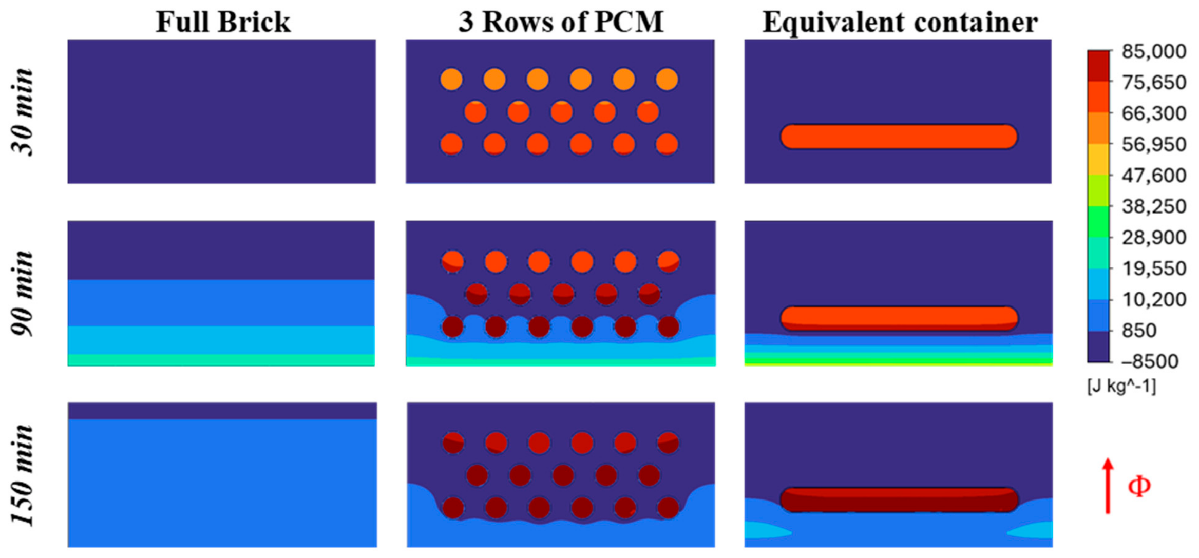
Table 7 show that this geometric simplification leads to a significant improvement in thermal performance. Indeed, the maximum temperature measured on the inner surface decreases from 21.73 °C to 20.87 °C, while the decrement factor drops from 0.088 to 0.044, representing an additional 50% reduction compared to the configuration with three PCM rows. Moreover, the time lag exceeds 1 h 30 min. The analysis of the total enthalpy maps presented in
Figure 12 highlights distinct thermal behavior across the three studied configurations. Total enthalpy corresponds to the sum of the sensible and latent energy of the material. It enables the modeling of heat transfer and phase change phenomena while characterizing the material’s ability to absorb or release heat during a process. For the Full brick, the heat front progresses homogeneously and continuously from the exposed face toward the inner face, with well-defined horizontal stratification bands appearing as early as 90 min, reflecting purely conductive diffusion without any latent storage effect. For the configuration with three rows of circular cavities (3 Rows of PCM), the maps reveal heat absorption concentrated around each capsule, with a progressive activation of the cavities from the most exposed row toward the inner rows. At 90 and 150 min, the cavities closest to the hot face reach high enthalpy levels (red-orange zones), while the more distant cavities remain partially underutilized, confirming a spatial heterogeneity in latent heat absorption inherent to multi-cavity geometries.
The equivalent container configuration, on the other hand, exhibits a markedly different behavior. As early as 30 min, the equivalent container concentrates a high-enthalpy zone within a continuous PCM volume, indicating rapid and more uniformly distributed latent heat absorption. At 90 and 150 min, the container acts as a nearly continuous thermo-capacitive barrier across the brick thickness: the thermal front is significantly slowed at this level, resulting in a more pronounced enthalpy gradient between the exposed and inner faces, as well as a greater delay in heat transmission toward the indoor space. This behavior is consistent with recent studies showing that continuous macro-encapsulation systems enhance latent heat storage effects and improve indoor temperature stabilization in building envelopes [
46], and aligns with literature emphasizing the importance of continuity in latent storage zones for improving the thermal performance of integrated bricks [
34].
Beyond thermal performance, this solution presents significant advantages from both technological and economic perspectives. Replacing the 17 individual tubes with a single container considerably reduces the number of manufacturing and assembly operations, particularly in the 3D printing of PLA, while also decreasing the number of interfaces between the adobe, the polymer, and the PCM. This simplification is likely to limit interfacial defects, improve component reproducibility, and reduce production costs at an industrial scale. These considerations are consistent with recommendations in the literature, which identify simplified macro-encapsulation as a particularly promising pathway for the large-scale deployment of PCM in construction materials [
46].
3.4. Long-Term Stability and Material Compatibility of Coconut Oil PCM
Although the present work focuses on the short-term thermal performance of PCM-integrated adobe bricks, the long-term stability of the selected PCM is an important criterion for practical building applications. Coconut oil has been identified as one of the most promising bio-based PCMs because of its appropriate phase-change temperature, renewable origin and relatively stable thermophysical properties. As highlighted in the comprehensive review by Saleel [
24], several experimental investigations reported only negligible variations in melting temperature and latent heat after repeated melting and solidification cycles. In particular, differential scanning calorimetry (DSC) measurements showed that both virgin and processed coconut oil maintained their thermal properties within the experimental uncertainty after up to 200 thermal cycles, indicating good thermal reliability for latent heat storage applications.
Material compatibility is another important aspect for practical application. In the proposed configuration, the PCM is completely encapsulated inside sealed PLA tubes before being inserted into the adobe brick. This design prevents direct contact between the coconut oil and the earthen matrix, thereby minimizing risks of oil migration, contamination of the porous structure, or modifications of the hygrothermal behavior of the adobe. Compared with direct impregnation techniques, encapsulation therefore offers additional protection for both the PCM and the surrounding construction material.
Nevertheless, although the available literature suggests good intrinsic thermal stability of coconut oil, the durability of the complete PCM-encapsulation-building system still requires further investigation. Long-term thermal cycling, oxidation under severe environmental conditions, possible aging of the PLA encapsulation, and mechanical degradation associated with repeated expansion and contraction cycles were not investigated in the present study. Dedicated experimental campaigns under realistic climatic conditions will therefore be required before large-scale deployment.
3.5. Limitations
The present work evaluates the thermal performance of the proposed concept over representative operating conditions but does not investigate the long-term durability of the PCM-encapsulation system. Although previous experimental studies summarized by Saleel [
24] indicate that coconut oil preserves its melting temperature and latent heat after several hundred melt-freeze cycles, the combined effects of thermal aging, oxidation, moisture, and prolonged environmental exposure require dedicated long-term investigations before large-scale implementation.
Another aspect deserving further investigation concerns the durability of the PLA encapsulation. Although this bio-based polymer is easy to process and suitable for 3D printing, its long-term behavior under repeated heating and cooling cycles remains uncertain. Thermal fatigue, mechanical degradation, and cracking may occur, especially under significant temperature gradients. In addition, the intrinsic porosity associated with the 3D printing process may promote moisture transfer or sealing defects, potentially affecting thermal performance and long-term system stability.
Second, the use of coconut oil as a phase change material presents limitations in terms of sustainability and regional relevance. While its thermophysical properties are favorable, it is not locally produced in Europe, leading to additional carbon emissions related to transportation and reliance on external supply chains. Furthermore, its long-term thermal stability under repeated melting/solidification cycles, as well as potential degradation mechanisms (such as oxidation or phase separation), require further investigation.
It should be noted that the quantitative thermal performance reported in this study is specific to the thermophysical properties of coconut oil. Although the absolute values of the decrement factor, time lag, and inner surface temperature would vary with another PCM, the observed trends regarding the influence of PCM geometry and positioning are expected to remain valid, provided that the selected PCM exhibits a phase transition temperature compatible with the operating thermal conditions. Furthermore, this numerical model assumes that the thermophysical properties of the PCM remain stable throughout the simulations. Possible long-term variations resulting from aging or repeated thermal cycling were not considered, although the available literature suggests that these effects remain limited for coconut oil within the investigated temperature range.
Moreover, introducing a larger cavity within the brick may induce non-negligible mechanical constraints. Such a geometry can affect compressive strength, creep resistance, and overall durability under cyclic thermo-mechanical loading. It may also generate stress concentrations around the cavity, increasing the risk of cracking in the adobe matrix.
Finally, practical and industrial considerations must be addressed, including compatibility with existing construction techniques, variability in raw earth properties, and the reproducibility of performance at a larger scale.
Therefore, despite the promising thermal results, further investigations, particularly focusing on durability, mechanical behavior, and life cycle assessment, are necessary to validate the relevance of this solution for real-world building applications.
4. Conclusions
This study demonstrates the strong potential of integrating a bio-based phase change material (PCM), namely coconut oil, into unfired earth bricks to enhance their dynamic thermal performance while preserving the environmental benefits of earthen construction. Although raw earth naturally provides high sensible thermal inertia, its relatively high thermal conductivity limits its ability to attenuate daily heat gains. The present work shows that combining the sensible heat storage capacity of adobe with the latent heat storage of coconut oil PCM constitutes an efficient strategy for improving passive thermal regulation in building envelopes. The CFD model, validated against dedicated experimental measurements performed on a PLA-encapsulated coconut oil sample, accurately reproduced the transient melting behavior of the PCM and therefore provided a reliable basis for analyzing heat transfer within the different brick configurations. The numerical investigation demonstrated that increasing the amount of PCM progressively improves thermal performance. Compared with the reference solid brick, the configuration incorporating three PCM rows reduced the maximum inner surface temperature from 24.83 °C to 21.73 °C, while decreasing the decrement factor from 0.247 to 0.088, corresponding to an attenuation of more than 94% of the imposed temperature fluctuations. At the same time, the thermal time lag increased from approximately 1 h 03 min to 1 h 30 min, representing an improvement of nearly 43%. These results confirm that increasing the PCM content enhances both thermal damping and heat storage capacity.
Beyond these global performance indicators, the spatial analysis of temperature and enthalpy distributions provided a better understanding of the physical mechanisms governing heat transfer. The thermal improvement originates from the combined action of three complementary effects: the sensible thermal inertia of the raw earth matrix, the additional conductive resistance introduced by the low thermal conductivity of the PLA encapsulation, and the latent heat absorbed by coconut oil during phase transition. The simulations also revealed that the thermal efficiency of the PCM strongly depends on its location within the brick, with the cavities closest to the heated surface being the most effectively activated during the thermal cycle. One of the most significant findings of this work is that replacing the seventeen individual PLA tubes with a single macro-encapsulated container of equivalent PCM volume not only simplifies manufacturing but also further improves thermal performance. This optimized configuration reduced the decrement factor to 0.044, representing an additional 50% reduction compared with the three-row PCM configuration, while maintaining a thermal time lag greater than 1 h 30 min. The continuous PCM volume promotes a more homogeneous activation of latent heat storage, reduces the number of interfaces between materials, and offers clear advantages in terms of manufacturing simplicity, reproducibility, and potential industrial deployment. Overall, this study demonstrates that combining geosourced materials with bio-based latent heat storage systems constitutes a promising solution for the development of low-carbon, high-performance building envelopes. The proposed macro-encapsulation strategy appears particularly attractive because it simultaneously enhances thermal efficiency and improves manufacturability, making it a realistic candidate for future sustainable construction applications.
Despite these promising results, several aspects deserve further investigation before practical implementation. Future work will focus on extending the present numerical investigation through comprehensive experimental validation at both the brick and wall scales under realistic climatic conditions. Additional research will also address the long-term thermal stability of coconut oil under repeated melting-solidification cycles, the durability of PLA encapsulation, the thermo-mechanical behavior of bricks containing large PCM cavities, and the influence of moisture transfer, which was not considered in the present model. In addition, a comprehensive parametric sensitivity analysis will constitute an important direction for future research, with the objective of quantifying the relative influence of the main material properties and boundary-condition parameters on the predicted thermal performance and identifying the most critical factors governing the behavior of PCM-enhanced earthen bricks. Finally, life cycle assessment, cost analysis, and the investigation of locally available European bio-based PCMs will be essential to assess the environmental and economic feasibility of large-scale implementation of this technology in sustainable buildings.