1. Introduction
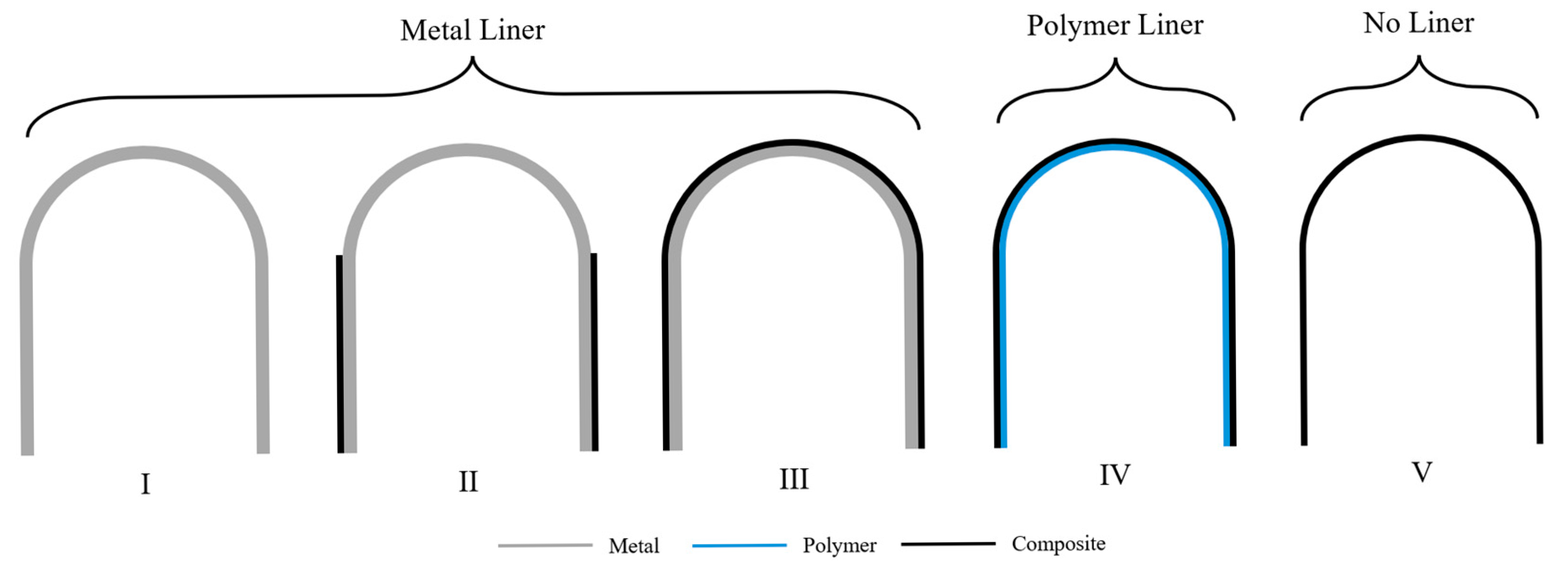
Hydrogen fuel storage remains a central challenge in enabling efficient and sustainable aerospace propulsion systems. Among the most demanding applications is the containment of cryogenic hydrogen in linerless composite pressure vessels. These Type V (see
Figure 1) cryotanks require materials capable of maintaining structural integrity, without significant leakage, at liquid hydrogen temperatures (−253 °C), while withstanding internal pressures. While challenging to realize, the weight savings associated with linerless composite tanks continue to be a compelling benefit driving current development efforts.
Thermoplastic matrix composites (TPCs) have emerged as strong candidates for cryogenic composite structures, particularly cryotanks, due to their inherent toughness, chemical resistance, and advantageous processing characteristics. A growing body of studies in the literature has reinforced their suitability for such applications, including multiple recent review papers. Saha and Sullivan [
1] reported that thermoplastics such as poly(ether ether ketone) (PEEK) and poly(ether ketone ketone) (PEKK) exhibit gas permeabilities several orders of magnitude lower at cryogenic temperatures compared to room temperature, attributed to the closing of gaps at the fiber/matrix interface and a reduced tendency for microcracking relative to thermoset epoxies. Nachtane et al. [
2] agreed, identifying thermoplastics as a promising technology for future cryotank designs. Similarly, Chen et al. [
3] highlighted the superior fracture toughness and microcrack resistance of high-performance thermoplastics at cryogenic temperatures, though they also noted that processing requirements and higher manufacturing costs had historically limited broader adoption. Sápi and Butler [
4] further supported these findings, concluding that thermoplastic composites demonstrate better retention of mechanical properties, such as strength, modulus, and impact resistance, compared to thermosets under cryogenic conditions, largely due to enhanced fiber/matrix bonding and reduced microcracking. Hohe et al. [
5] likewise emphasized the potential of carbon fiber-reinforced thermoplastics, citing their superior toughness and microcrack resistance compared to thermosets as key advantages for cryotank applications.
Numerous other studies have evaluated the cryogenic performance of thermoplastic matrix composites, reflecting a sustained interest spanning over two decades. Early work by Wang and Sun [
6] highlighted the development of residual stresses during cooldown in PEEK composites, underscoring critical design considerations for cryogenic use. Whitley and Gates [
7] further validated the structural viability of thermoplastic composites at cryogenic temperatures through combined experimental and simulation approaches. Building on this foundation, Grogan et al. [
8] identified microcrack formation in cryogenically cycled carbon/PEEK laminates, providing detailed damage characterization that revealed the superior toughness and damage tolerance of thermoplastics compared to thermosets. Their subsequent study [
9] connected laminate design parameters to hydrogen permeability in tape-laid thermoplastic tanks, emphasizing the importance of microstructural control in preserving structural integrity and minimizing leakage. Complementing these experimental insights, Grogan et al. [
10,
11] developed advanced XFEM and cohesive zone modeling frameworks to simulate fatigue delamination and microcracking, capturing the complex crack propagation and permeability behavior intrinsic to thermoplastic composites. This focus on C/PEEK arose from thermoplastics’ enhanced fracture toughness, better impact resistance, and improved thermal performance at cryogenic temperatures, qualities essential for demanding applications such as cryotanks. At this time, Comer et al. [
12] demonstrated that laser-assisted tape placement can manufacture carbon/PEEK laminates with minimal cryogenic strength degradation. Flanagan [
13] also corroborated the low permeability and structural reliability of carbon/PEEK composites for space-based cryogenic storage systems, underscoring their growing adoption in advanced cryogenic applications.
More recent investigations have continued to build on these findings; for example, Schlothauer et al. [
14] showed that tailoring microstructure and morphology can significantly enhance transverse performance under cryogenic conditions. Nikonovich et al. [
15] confirmed that PEEK-based composites maintain beneficial thermal and mechanical properties at low temperatures, and Pourahmadi et al. [
16] employed micromechanical modeling to accurately predict stiffness in AFP-fabricated carbon/PEEK composites relevant to cryogenic environments. Additionally, Wang et al. [
17] investigated the sealing behavior of thermoplastics, highlighting the influence of strain rate and temperature sensitivity on performance.
While not specifically focused on TPCs, the highly relevant foundational work on cryogenic composites by Roy and Benjamin [
18] should be mentioned. This work created a unique model to predict permeation by deriving expressions for delaminated crack opening displacement and applying Darcy’s law to model gas flow through networks formed by transverse matrix cracks and inter-ply delaminations. Building on this, Nair and Roy [
19] extended the model to generic laminate configurations, introducing the concept of “stitch cracks” observed in off-axis plies that do not necessarily span the entire ply width. A number of studies since then have utilized the approach introduced in these papers.
While the literature demonstrates the potential for TPCs for cryotanks, there is a clear need for advanced design tools capable of evaluating the performance of composite cryotanks across thermoplastic matrix systems and laminate configurations under realistic service conditions. These tools must capture the complex interactions among material behavior, damage evolution, and structural response across the temperatures encountered by in-service cryotanks. Accurate evaluation requires reliable input data, yet comprehensive thermal and mechanical characterization of thermoplastic composites across this full temperature range remains limited. To address this gap, this study employs molecular dynamics (MD) simulations to predict consistent, temperature-dependent properties of thermoplastic matrices. This approach enables the generation of reliable, fine-scale data where experimental measurements are challenging or impractical, providing the foundational material inputs necessary for robust multiscale modeling and performance prediction of the cryogenic composite structures.
The nano-scale MD thermoplastic property predictions are used as input to a multiscale micromechanics model considering both the micro (fiber/matrix) and macro (ply layup) scales in a coupled manner. This enables the capture of residual stresses at the fiber/matrix constituent scale, which then influences the progressive damage predictions during the applied mechanical loading. The result is a realistic evaluation of promising thermoplastic matrix materials for use in linerless TPC cryogenic tanks.
2. Multiscale Micromechanics Model
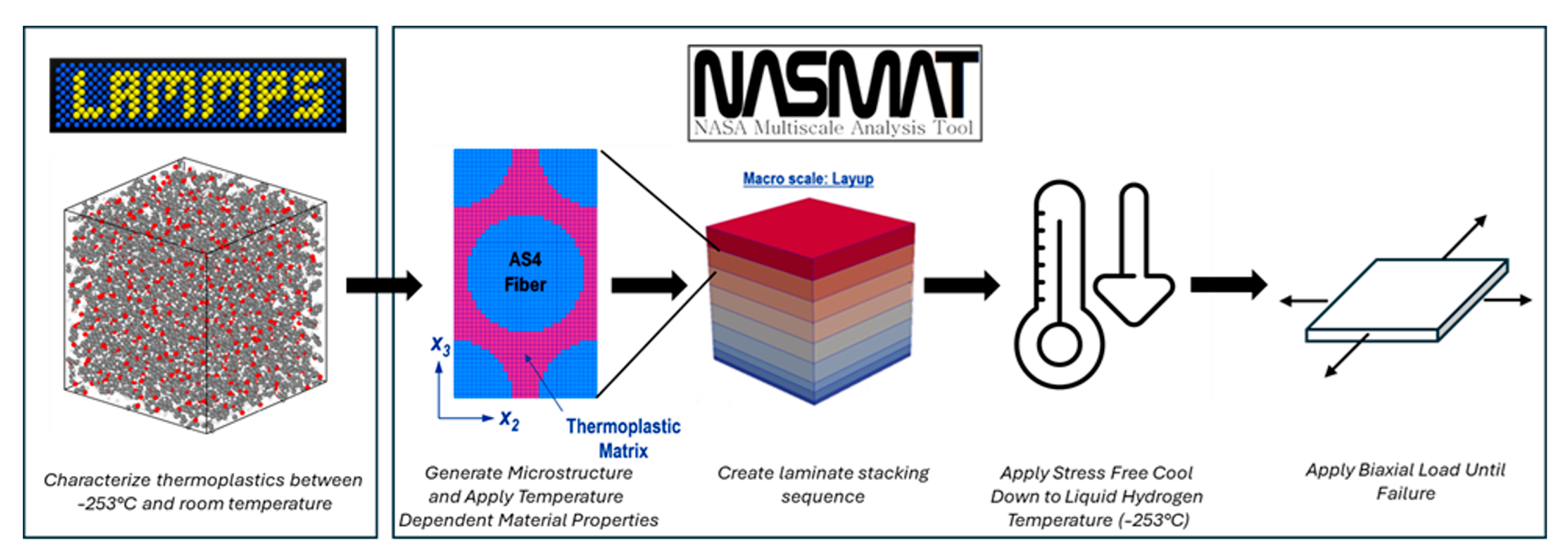
The multiscale modeling approach for the TPCs is illustrated in
Figure 2. At the lowest (nano) length scale, MD simulations were conducted using the LAMMPS software (LAMMPS stable release 29 September 2021) [
20] to obtain the properties of each neat thermoplastic material at 27 °C, −183 °C, and −253 °C. These properties were then used as input for the matrix in a micromechanics analysis for each ply, and these micromechanics simulations were coupled within a global, macro-scale micromechanics model representing the ply layup. The AS4 carbon fiber was considered in this study. It was treated as temperature-independent and transversely isotropic, with the properties given in
Table 1.
As shown in
Figure 2, at the micro scale, a repeating unit cell (RUC) with hexagonally packed fibers was represented (32 × 56 subvolumes with a fiber volume fraction of 0.603). For the macroscale, the layup RUC representation is essentially 1-D, with the ply materials stacked in the Z-direction. It should be noted that, while the RUC accurately represents the material behavior of the layup, it is not capable of predicting bending as would a plate theory. That is, because it is repeated infinitely, the RUC automatically achieves homogenization, and no bending-extension coupling can be captured.
Four layups that are realistic for cryotanks have been considered. These are (1) a quasi-isotropic [0/±45/90]
s layup, (2) a hard layup [0
4/±45/90
2]
s with a higher percentage of zeros, (3) a [0/±30/±60]
s layup, and (4) a [55/5/−55/−5] Double-Double layup. Note that the 0-direction refers to the hoop direction in this study. Double-Double is a family of laminates developed by Tsai [
22,
23] that can offer performance and manufacturability advantages. Double-Double layups involve two ± angles in a four-ply repeating block, such as [Φ/Ψ/−Φ/−Ψ]
n, where the ordering of the plies within a given repeating block defines the Type. Herein, one particular Double-Double layup, with ply ordering considered as Type II [
22], has been considered with a 5° angle (close to the hoop direction) and an intermediate 55° angle to provide some stiffness and strength in the direction that would correspond to the longitudinal tank direction. Note that the chosen Double-Double layup, as well as the other layups considered, have not been optimized for the current cryotank application.
2.1. Molecular Dynamics Modeling of Neat Thermoplastics
Molecular dynamics (MD) simulations were used to predict key physical, thermal, and mechanical properties of six high-performance thermoplastic polymers: PEEK, Elium, LM-PAEK, PEKK, poly(ether imide) (PEI), and polyimide, across a wide temperature range down to –253 °C, relevant for liquid hydrogen storage. These MD simulations are described in detail by Bamane et al. [
24] and are briefly summarized here. Using the LAMMPS simulation package and the IFF-R force field, atomistic models of the amorphous thermoplastics were built, equilibrated, polymerized (when applicable), and subjected to controlled cooling and mechanical deformation protocols. The simulations yielded temperature-dependent predictions of mass density, free volume, thermal shrinkage, Young’s modulus, yield strength, Poisson’s ratio, and the coefficient of thermal expansion (CTE). These properties were determined at 27 °C, −183 °C (liquid oxygen), and −253 °C (liquid hydrogen), providing consistent input for cryogenic composite design. The thermoplastic systems, especially PEEK, LM-PAEK, and polyimide, were found to exhibit low shrinkage, stable stiffness, and favorable CTE at cryogenic temperatures, supporting their suitability as matrix candidates in composite cryotank applications where experimental characterization is challenging. The neat thermoplastic properties are provided in
Table 2. Bamane et al. [
24] provide some validation comparisons to experimental data for the MD-predicted density, Young’s modulus, and yield strength.
It should be emphasized that all of the neat thermoplastics were modeled as amorphous, whereas it is well-known that PEEK, LM-PAEK, and PEKK are semi-crystalline. As such, the predictions involving these materials should be considered estimates. Future work will consider the semi-crystalline nature of these thermoplastics via additional, lower length scales in the model to capture the crystalline phase and its microstructure. See [
25,
26] for examples of this approach.
2.2. Multiscale Recursive Micromechanics
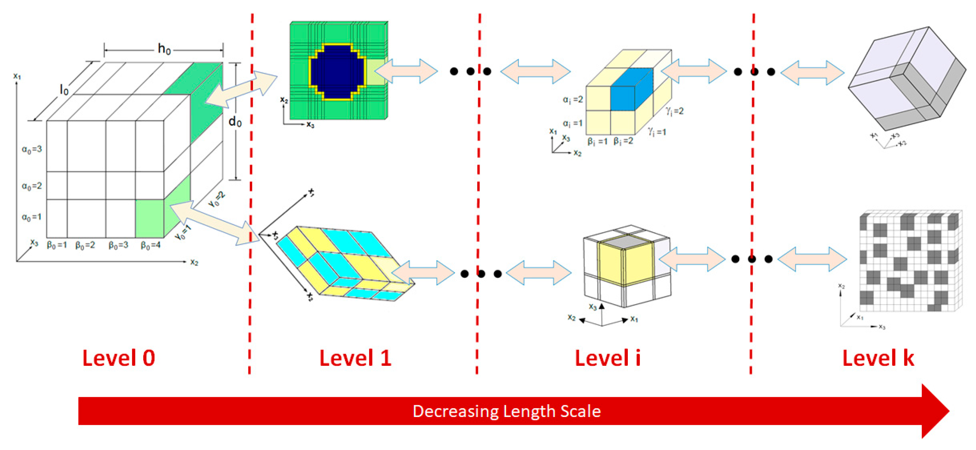
In multiscale recursive micromechanics (MsRM), synergistic material modeling is achieved by linking scales such that the homogenized response of a representative unit cell (RUC) at scale
i becomes the local input for a subvolume at the next finer scale,
i + 1. This coupling, illustrated conceptually in
Figure 3, may include coordinate transformations to reconcile differences in orientation between scales. Upward and downward transfer of information is facilitated through homogenization and localization, respectively. Within the NASMAT framework, a flexible selection of micromechanics models, ranging from Mori-Tanaka and the Generalized Method of Cells (GMC) to the High-Fidelity Generalized Method of Cells (HFGMC) and full finite element, can be applied at any number of recursive scales. While
Figure 3 shows two branches for clarity, the framework supports arbitrarily deep hierarchies to capture the full multiscale nature of advanced composite materials.
Each micromechanics model computes a strain concentration tensor,
, which maps the global strain at level
i,
, to the local strain in subvolume,
αi,
The local stress components are computed using material-specific constitutive laws:
where
is the local material stiffness tensor for a given subvolume. Global averages for the stresses are obtained by volume-weighted sums across all subvolumes:
with
denoting the relative volume fraction of each subvolume. The effective (homogenized) stiffness and thermal conductivity tensors for the RUC are then computed as:
To propagate material behavior between scales, homogenized properties from level
i + 1 are mapped to level
i using appropriate transformation tensors,
where
and
are the appropriate second and fourth order coordinate transformation tensors if the two linked RUCs are oriented differently in space.
Herein, the well-documented HFGMC micromechanics theory [
27,
28] was used to predict the behavior of the TPCs. Summarizing, this semi-analytical approach analyzes a repeating unit cell composed of rectangular parallelepiped subvolumes. Assuming a quadratic displacement field in each subvolume, equilibrium is enforced within each subvolume, and continuity between subvolumes, as well as periodicity, are enforced via the surface-averaged tractions and displacements. This results in a system of linear algebraic equations that can be solved to obtain the effective (homogenized) properties of the RUC, as well as the local fields in each subvolume via the strain concentration tensor, see Equation (1). Both doubly periodic (considering a 2-D RUC) and triply periodic (considering a 3-D RUC) formulations of the HFGMC theory are available [
27,
28]. The HFGMC theory and MsRM have been implemented in the NASA Multiscale Analysis Tool (NASMAT) [
29,
30], which includes nonlinear effects such as progressive damage and plasticity. The progressive damage simulations presented here are based on a simple subvolume elimination approach. The simulation applies the loading incrementally, and once a subvolume (thermoplastic or fiber) reaches the specified material strength (or failure strain), its stiffness is instantaneously reduced to a low value. Recall that, for the thermoplastic materials, the yield strength predicted by the MD simulations was used as the material strength. For the AS4 fiber, only longitudinal (fiber-direction) failure was considered (using the max strain criterion, see
Table 1). It is well-known that simple subvolume elimination, while very numerically stable, leads to discretization-dependent results for methods that are able to capture localization (such as HFGMC and the finite element method) [
28]. As such, in the present study, the micro-scale subvolume discretization was kept fixed to keep the results consistent with each other. Future work will employ energy-based progressive failure methods incorporating a length scale to make the results more discretization objective and quantitatively predictive.
3. Results and Discussion
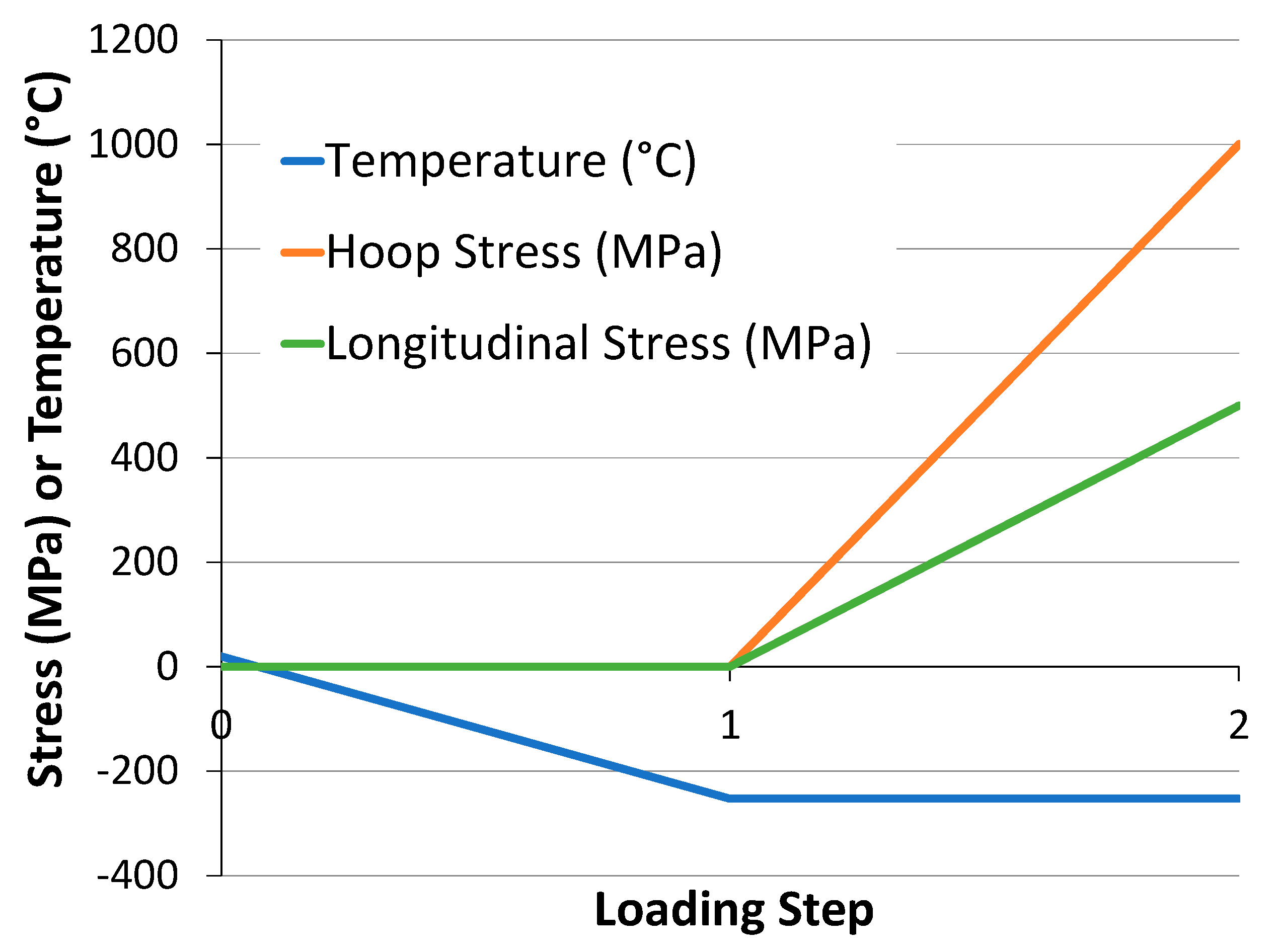
The progressive damage simulations began with a stress-free thermal cooldown from 25 °C to −253 °C, followed by mechanical loading under a 2:1 hoop-to-longitudinal stress ratio, replicating the acreage service conditions in a cylindrical cryotank (
Figure 4). This loading history induces thermal stresses due to CTE mismatch, both between the fiber and matrix and among the plies, setting the stage for subsequent matrix microcracking.
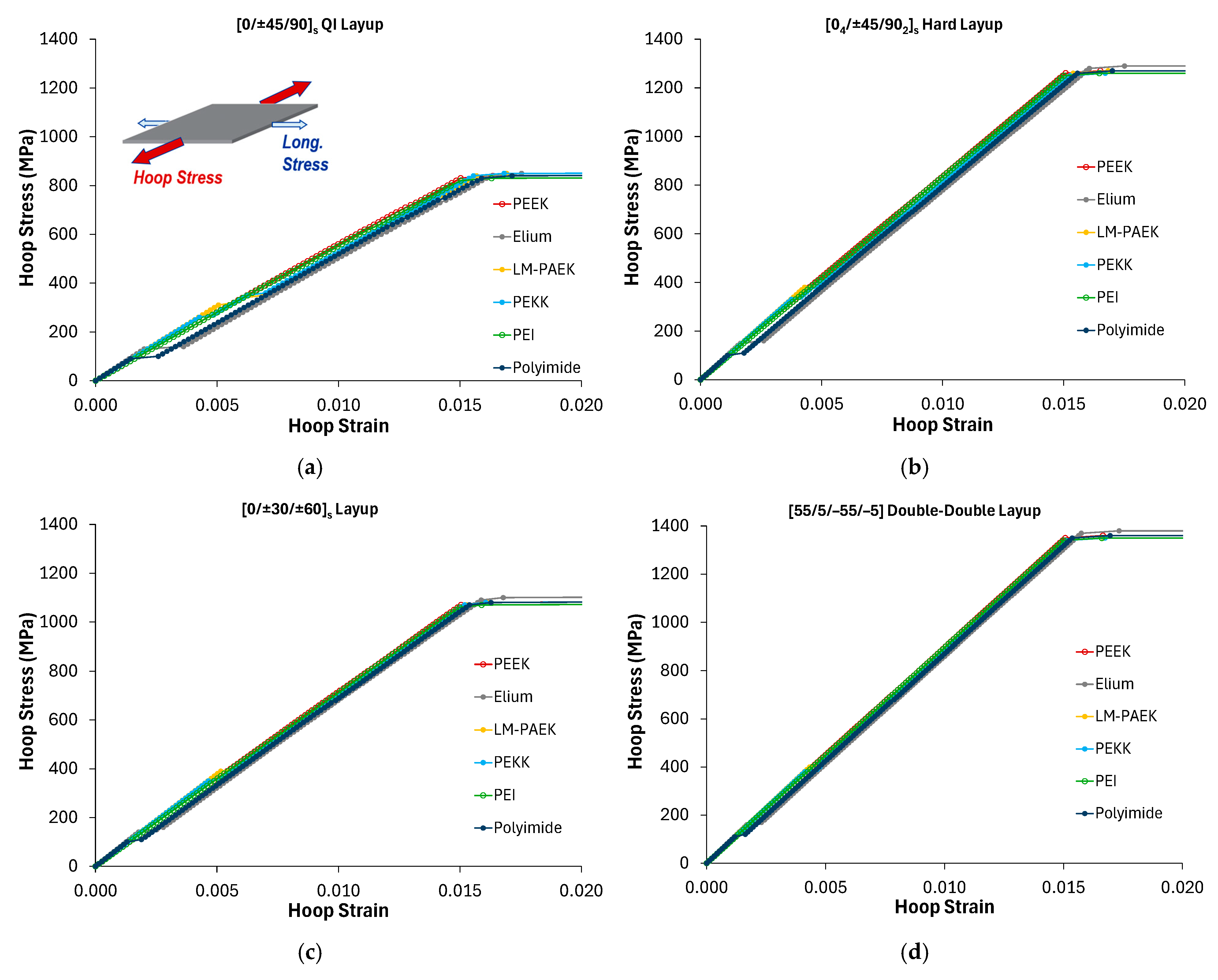
Figure 5 presents the hoop stress–hoop strain responses for each of the four layups, quasi-isotropic [0/±45/90]
s, hard [0
4/±45/90
2]
s, [0/±30/±60]
s, and the Double-Double configuration, and the six thermoplastic matrices. In all cases, the onset of matrix damage manifests as sudden strain jumps under stress control, serving as a proxy for microcrack initiation and, by extension, potential permeability. While the ultimate burst stress (associated with fiber failure) was similar across materials and layups, the predicted damage initiation stresses varied widely. Notably, the PEEK and PEI matrix composites exhibited microcracking during cooldown, prior to any mechanical loading, indicating poor cryogenic performance for these thermoplastic systems compared to the others.
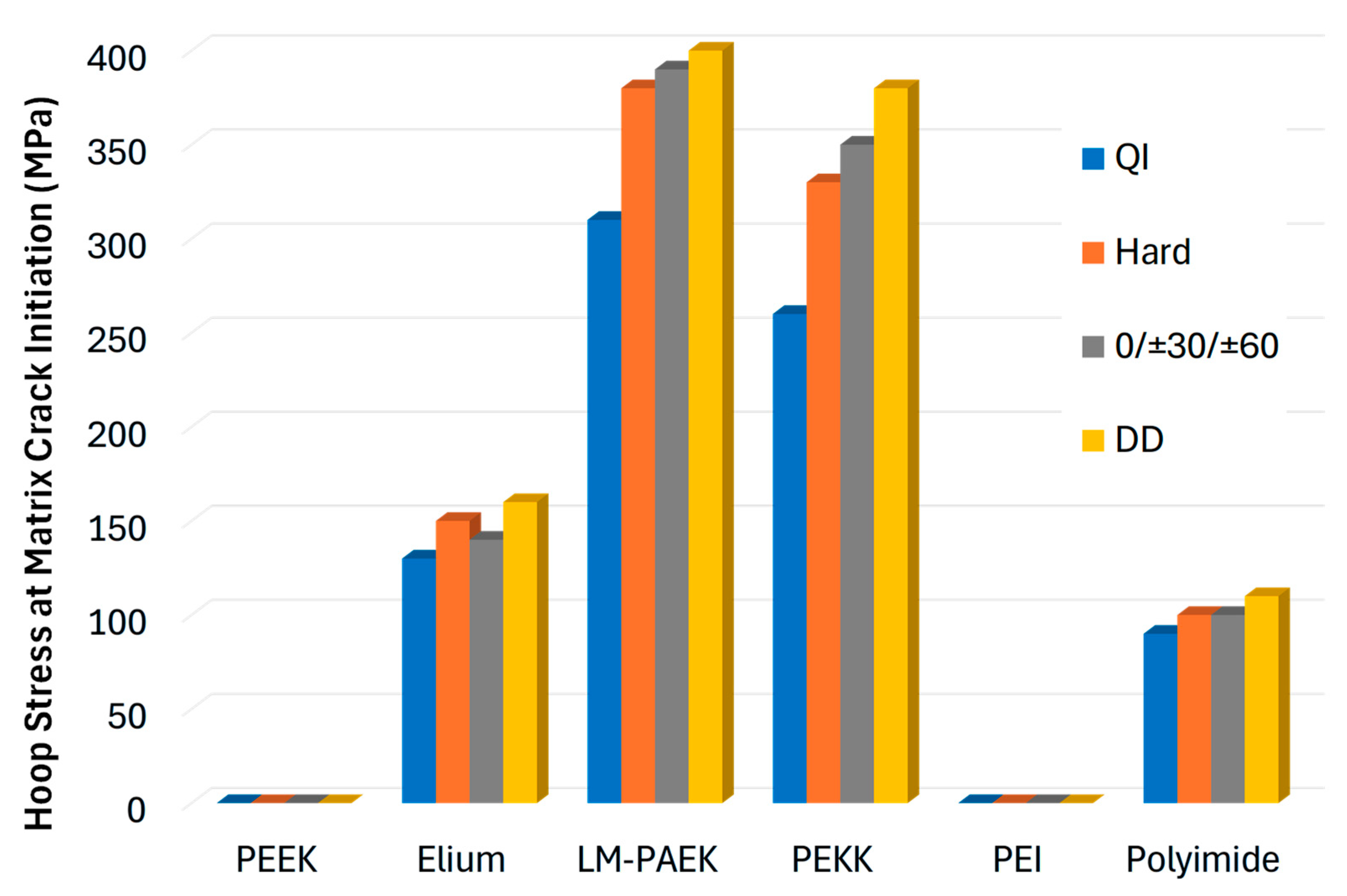
A clearer comparison of matrix performance is provided in
Figure 6, which plots the composite hoop stress at first microcrack initiation for each combination of layup and thermoplastic matrix. Across all four layups, the composites with PEEK and PEI matrices exhibited microcrack initiation during the cooldown, prior to application of any biaxial mechanical loading. Microcracking occurred earlier in the PEI matrix composites (at −191 to −198 °C) compared to the PEEK matrix composites (at −226 to −233 °C). The [55/5/−55/−5] Double-Double layup generally performed the best among the layups in terms of damage-initiation stress. For LM-PAEK and PEKK matrices, the ordering of the layups was consistent, with the [0/±30/±60]ₛ performing second best, followed by the hard and quasi-isotropic (QI) layups. This is generally expected as the quasi-isotropic layup has only 25% of the plies in the more highly loaded hoop direction, whereas the other three layups are purposely biased toward hoop-direction reinforcement. For Elium, the trend was different, with the hard configuration performing marginally better than the [0/±30/±60]ₛ. Recall that these layup candidates are representative and not truly optimized for the cryotank application. These results do, however, imply that if layup optimization were performed, it should be done for each layup and matrix material combination independently, as
Figure 6 shows that different laminates perform better when paired with certain matrix materials.
Among the thermoplastic matrices, LM-PAEK and PEKK stood out, achieving the greatest resistance to initial cracking under combined thermal and mechanical loading for all layups considered. Note that predicting actual permeability is beyond the scope of this study. This would require a 3D model to capture the cracking path (c.f., refs. [
11,
18]). Also, the simple, brittle subvolume elimination damage model does not account for material toughness. Use of a more advanced energy-based model would improve the fidelity of the performance predictions (but would require material toughness data as input). As mentioned previously, the results presented herein should be considered as representative and likely lower bounds on the TPC performance because the properties of the thermoplastic matrices were obtained from MD simulations treating them as purely amorphous, rather than semi-crystalline.
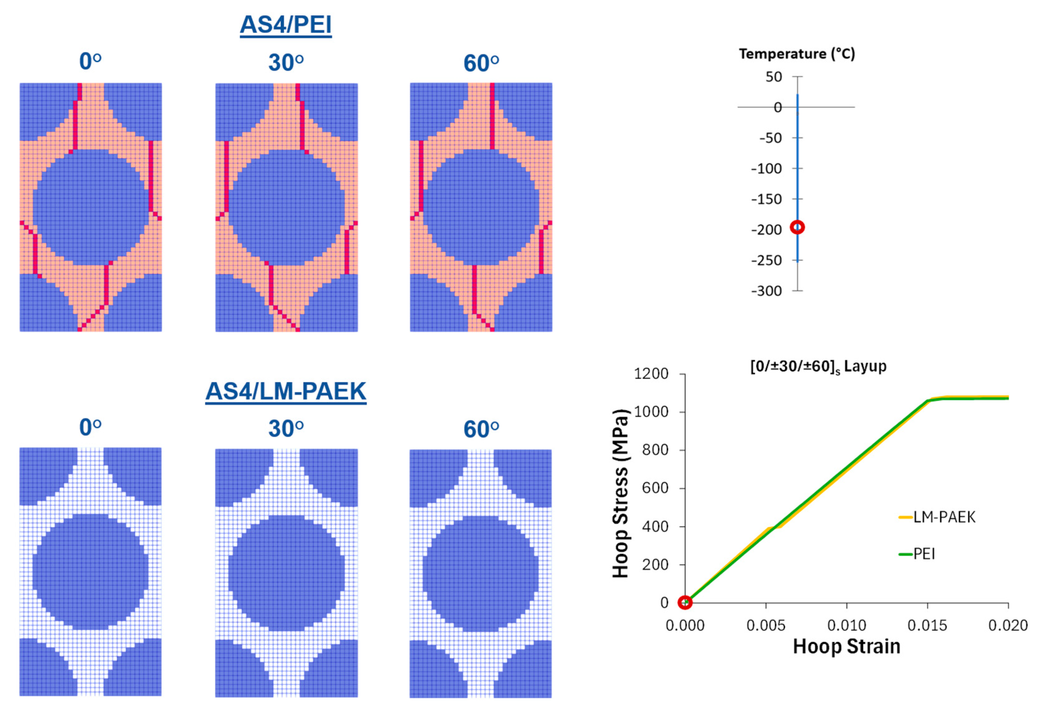
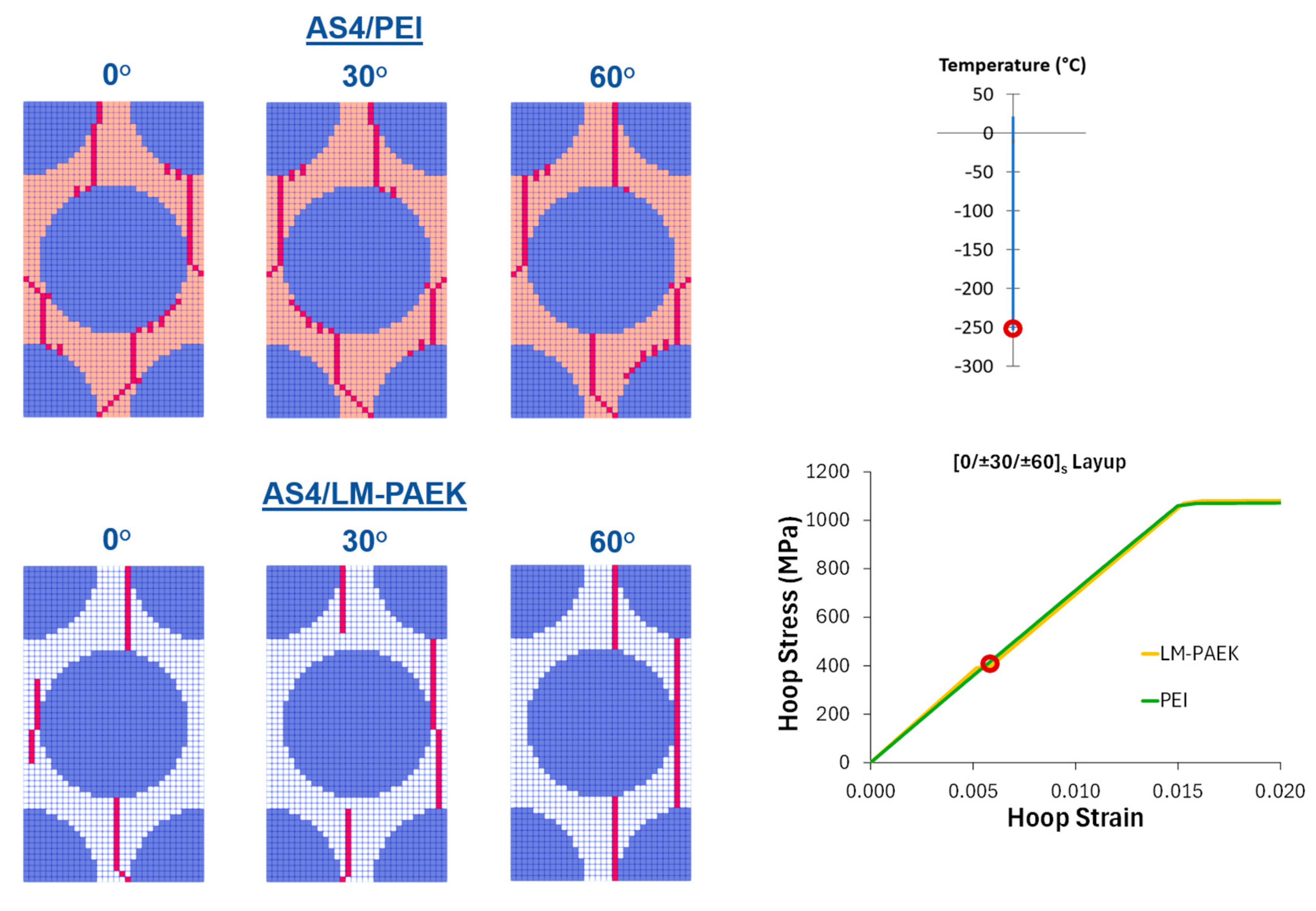
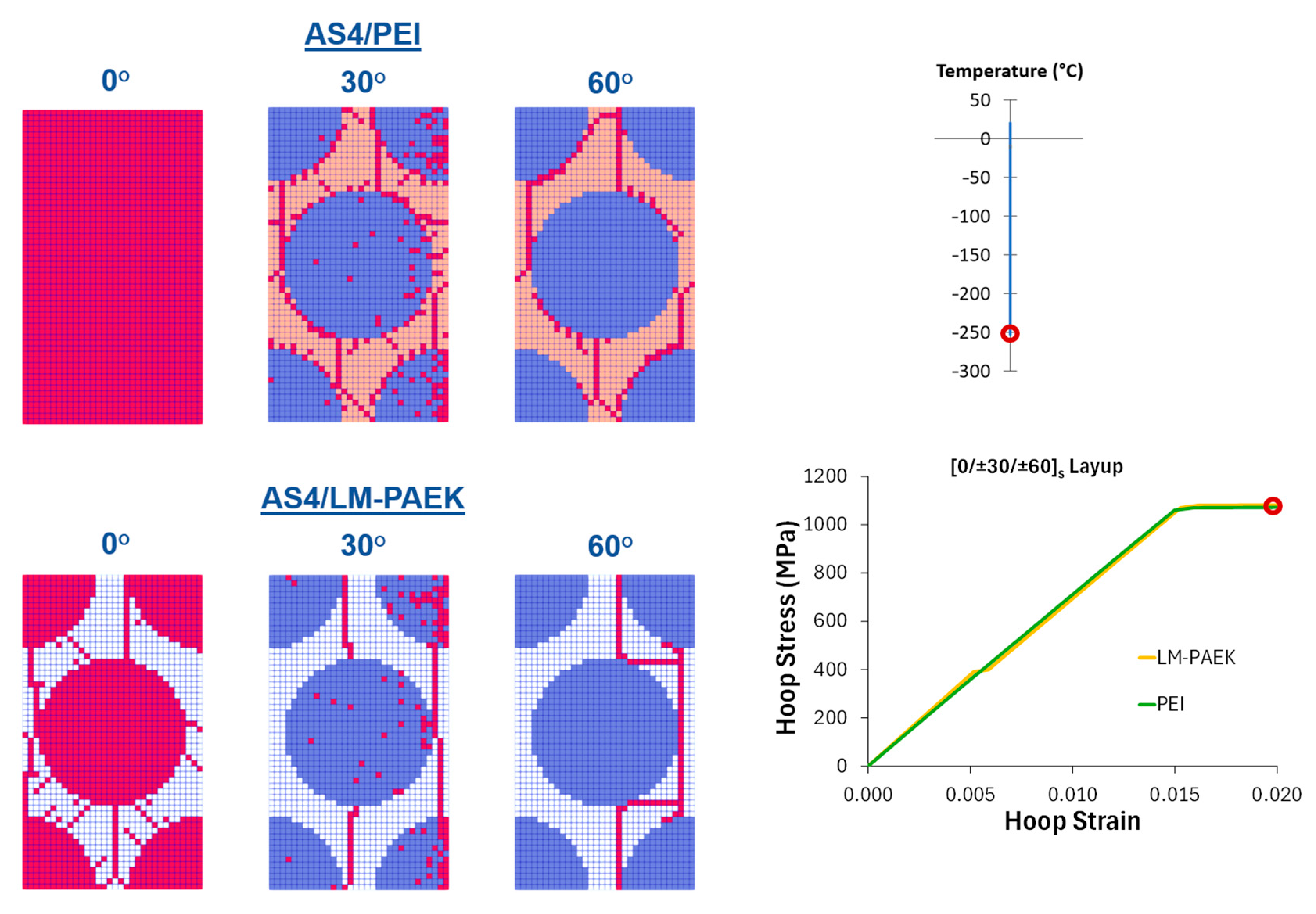
Detailed damage patterns for the two extremes, AS4/PEI (worst performing) and AS4/LM PAEK (best performing), in the [0/±30/±60]ₛ layup are compared in
Figure 7,
Figure 8 and
Figure 9. During cooldown (
Figure 7), PEI shows extensive microcracks emerging near −198 °C, whereas AS4/LM PAEK remains undamaged. Under the subsequent mechanical loading (
Figure 8), AS4/PEI exhibits some continued damage propagation, while the AS4/LM PAEK microcracking is first seen only as the hoop stress approaches 400 MPa. At final failure (
Figure 9), both composites “burst” when fiber strength is exceeded in the 0° plies, confirming that matrix toughness governs early damage but that fiber properties control ultimate burst.
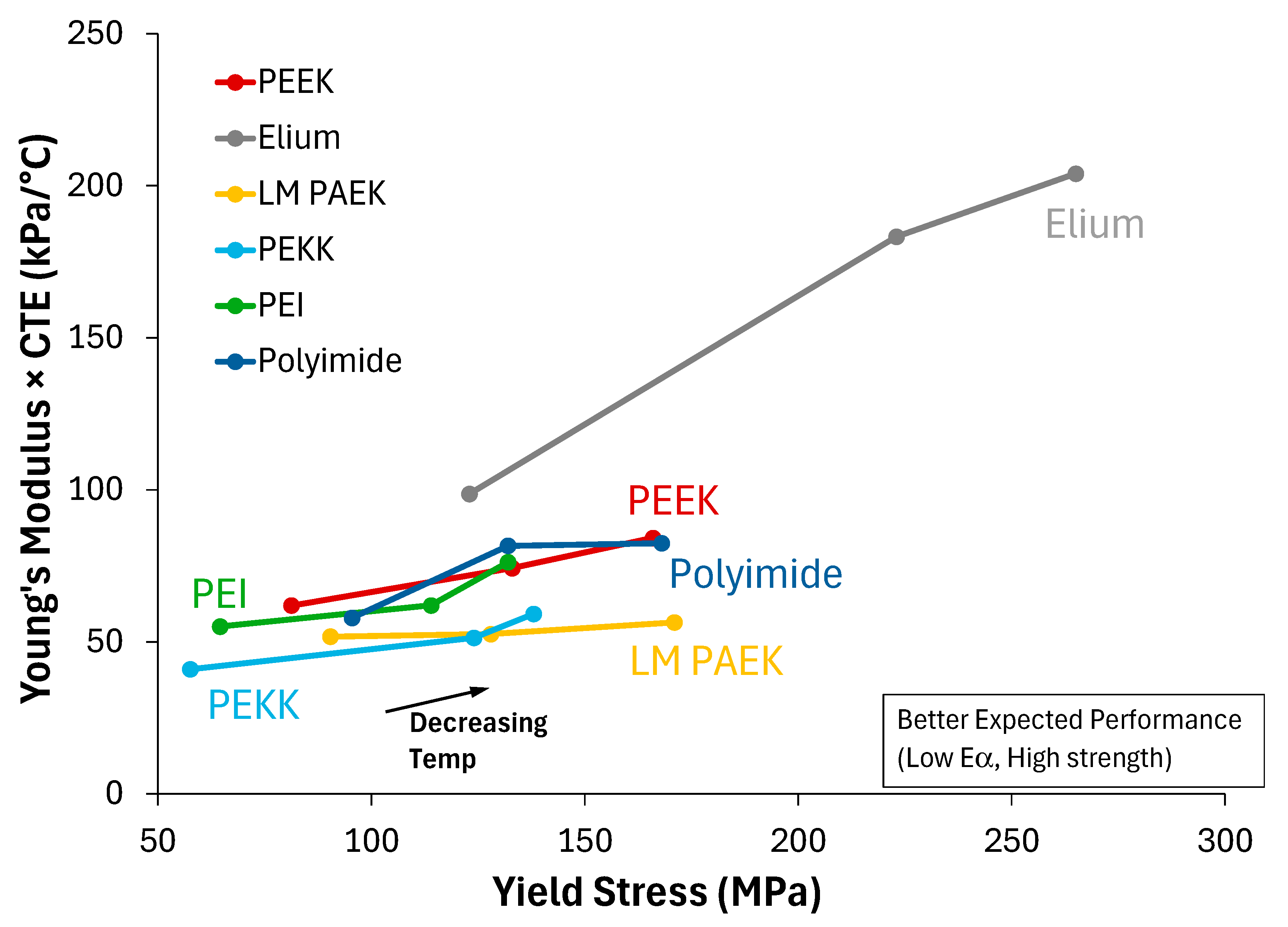
In an attempt to tie the performance of the TPCs back to the thermoplastic matrix properties provided by MD,
Figure 10 shows the thermoplastic Young’s modulus times CTE vs. yield stress for the six thermoplastics at the three temperatures (see
Table 2). The Young’s modulus times CTE (E·α) drives the thermal stresses from mismatch with the fiber (since the fiber has a negative longitudinal CTE). The yield stress, which is used as the matrix strength in the progressive damage simulations, provides the resistance to the thermal stresses and the applied mechanical stresses. As such, high yield stress and low E·α would indicate better expected performance, corresponding to the lower right of the plot in
Figure 10. Clearly, Elium is an outlier, with the highest strengths and the highest E·α. This material had mid-range performance in
Figure 6. The best performing thermoplastics, LM-PAEK and PEKK, have the lowest E·α, with strengths reasonably close to the other thermoplastics (aside from Elium). PEKK’s strength at the lowest temperature (furthest point to the right in its curve) is quite a bit lower compared to LM-PAEK, and even PEEK and polyimide, but it has a much lower E·α compared to these two lower-performing thermoplastics. Examining PEI, which, recall, had the worst performance of all the thermoplastics studied, it has the lowest strength at −253 °C (furthest point to the right in its curve), and it also has a significant jump in E·α from −183 to −253 °C. However, given its poor performance, with TPC matrix microcracking during the cooldown, one might expect it to appear further from the other thermoplastics in the plot shown in
Figure 5. The PEEK TPC also exhibited matrix microcracking during the cooldown, yet it is close to polyimide in
Figure 5. Obviously, in the multiscale thermo-mechanical micromechanics simulations of the layup and the microstructure, there are complex, multiaxial interactions occurring that cannot be gleaned from a simple plot of the matrix input properties.
To further frame the presented results and provide evidence of their validity, predictions were made for a unidirectional AS4/PEEK composite at room temperature using the same 0.603 fiber volume fraction RUC employed within the layup plies (see
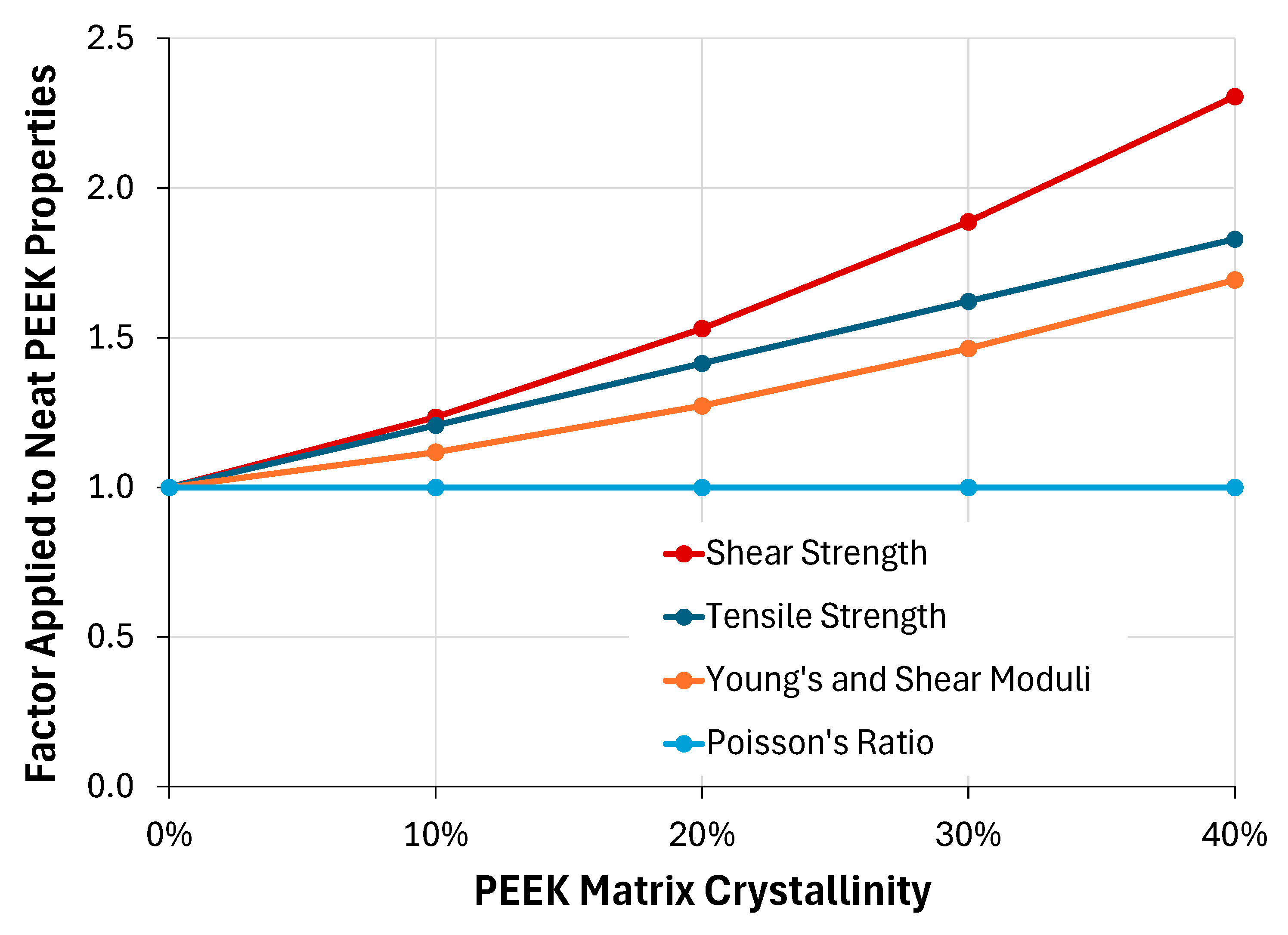
Figure 2). To compare with test data from the literature, in which the PEEK matrix is typically semi-crystalline, estimates of the PEEK matrix properties as a function of crystallinity percentage (by volume) were first performed. Towards this end, the empirical equations presented by Talbott et al. [
31], which provide the Young’s modulus, tensile strength, and shear strength of neat PEEK as a function of crystallinity, were employed. For consistency with the neat PEEK properties employed herein (see
Table 2), which, recall, represent fully amorphous PEEK, the Talbott et al. [
31] equations were used to determine the percentage change in the neat PEEK properties as a function of crystallinity. These were then applied to the amorphous neat PEEK properties given in
Table 2 to arrive at consistent semi-crystalline properties. The employed percentage change factors are plotted in
Figure 11. Note that Talbott et al. [
31] also provided an empirical equation for the shear modulus of neat PEEK as a function of crystallinity, but the use of this equation resulted in unrealistic Poisson’s ratios. As such, it was assumed that Poisson’s ratio of the neat PEEK remains constant with crystallinity, which, in accordance with isotropy, resulted in the shear modulus changing by the same factor as the Young’s modulus. Further, Talbott et al. [
31] did not address the effect of crystallinity on CTE, but evidence in the literature [
26,
32] suggests a much smaller impact compared to that observed on the mechanical properties. As such, it was assumed that the thermal conductivity of the neat PEEK was not affected by the degree of crystallinity.
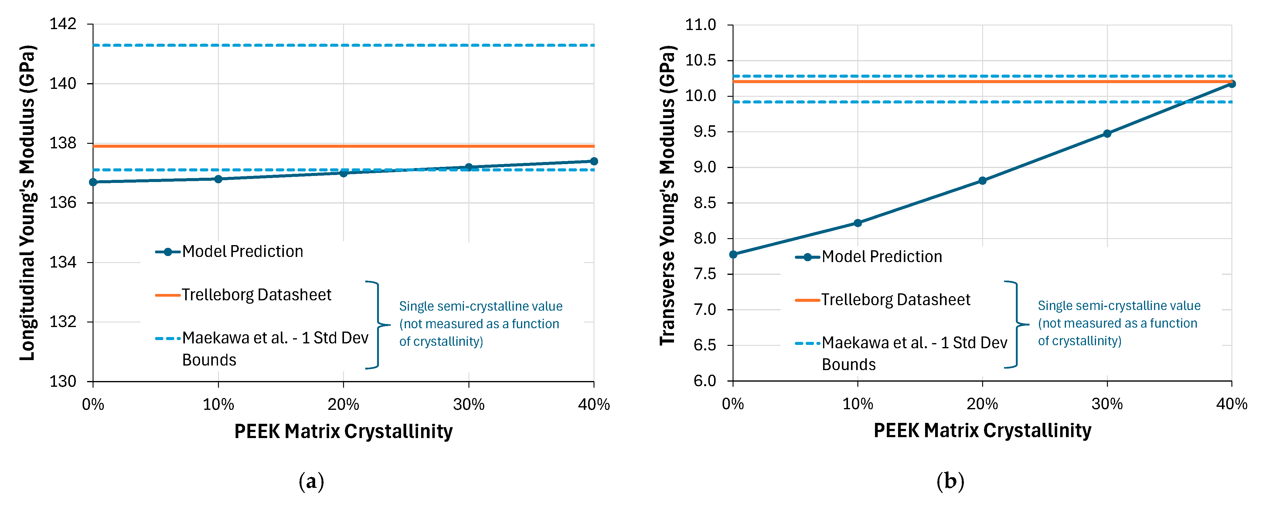
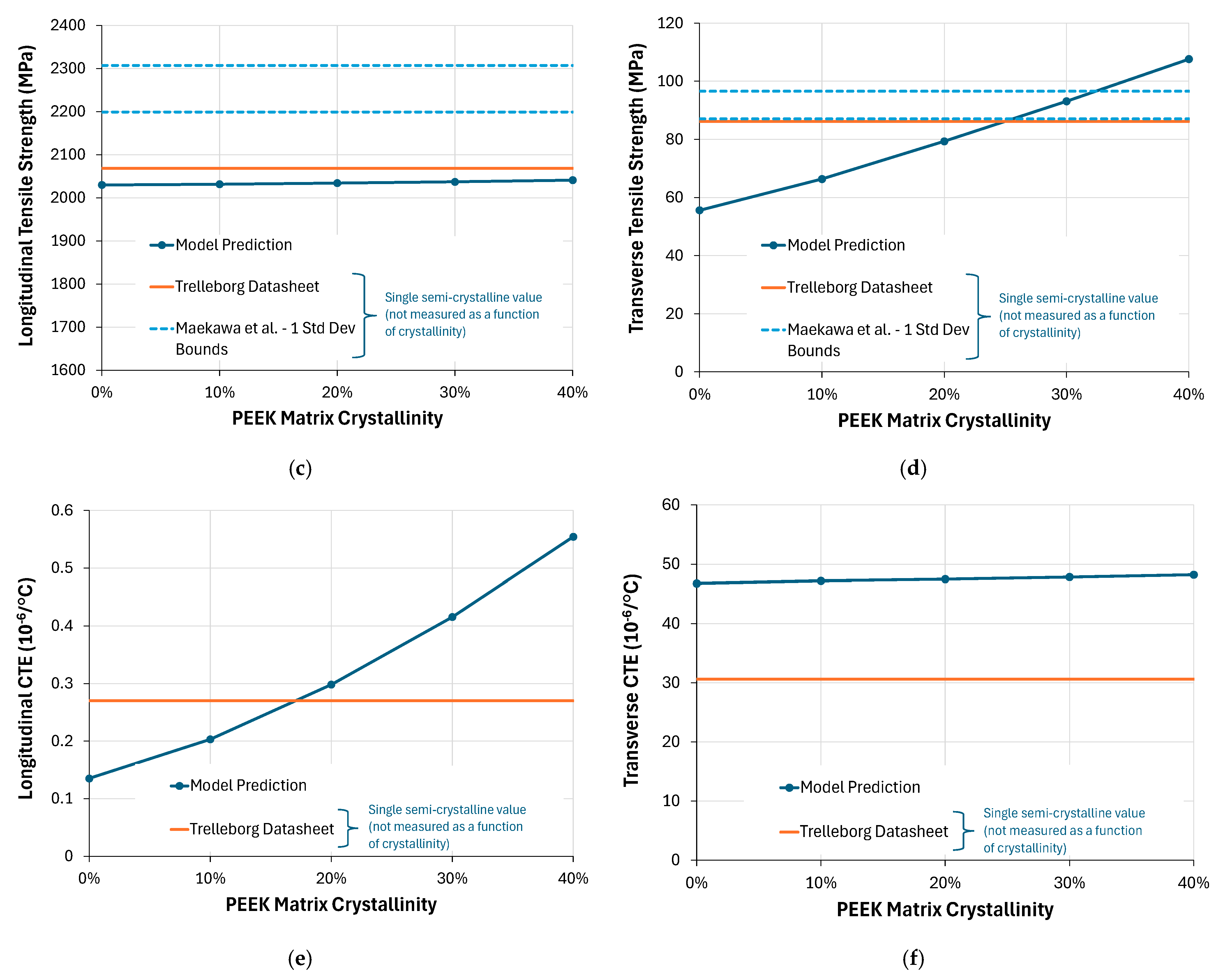
The predictions of the 0.603 fiber volume fraction unidirectional AS4/PEEK properties are shown in
Figure 12, with comparison to test data values from a Trelleborg datasheet [
33] and statistical mechanical test data given by Maekawa et al. [
34]. These test data are for semi-crystalline PEEK matrix composites and are not a function of the PEEK matrix crystallinity. Rather, they likely represent a typical PEEK crystallinity value of approximately 33% [
35]. A range of ±one standard deviation of the data reported by Maekawa et al. [
34] is shown. Note also the significant differences in the ordinate ranges in the plots of
Figure 12.
Figure 12a,c show that, for the longitudinal (fiber-direction) properties, the model predictions are only weakly influenced by matrix degree of crystallinity (as expected in this fiber-dominated direction). The agreement with test data is good, but it suggests the employed AS4 fiber modulus and strain to failure (
Table 1) might be slightly too low. Also, as expected, the predicted transverse Young’s modulus and tensile strength (
Figure 12b,d) show a strong dependence on the PEEK degree of crystallinity. Further, at realistic PEEK crystallinities (~33%), the predictions agree quite well with the test data, with the predicted transverse Young’s modulus slightly underpredicted and the transverse tensile strength slightly overpredicted.
The predicted AS4/PEEK longitudinal CTE is clearly realistic and in range with the (very low) test data in this fiber-dominated direction (
Figure 12e).
Figure 12f suggests that the transverse CTE might be overpredicted. However, it has been assumed here that the PEEK matrix CTE is not a function of crystallinity, so the transverse CTE is highly dependent on the amorphous CTE value, which is quite high at room temperature (67.7 × 10
−6/°C, see
Table 2). In addition, the transverse CTE predicted by the composite is quite dependent on the fiber transverse CTE, which is typically not a well-known property.
While the approach taken here to account for the crystallinity in the model predictions is quite simplistic, these results indicate that the AS4/PEEK model is reasonable and realistic.
Figure 12b,d suggest that treating the PEEK matrix as amorphous rather than semi-crystalline has resulted in underpredicting the AS4/PEEK transverse Young’s modulus and strength by 23% and 39%, respectively, compared to the mean values reported by Maekawa et al. [
34].
Figure 12f suggests an overprediction of the transverse CTE. These uncertainties would tend to lower the TPC performance as predicted by the model, again pointing to the results herein as lower bounds. As mentioned previously, future work will address this shortcoming by explicitly modeling the crystalline microstructure, starting with MD predictions of the amorphous and crystalline thermoplastic phases.
Overall, these results underscore the critical importance of selecting both matrix material and laminate architecture to maximize microcrack resistance, and hence permeability resistance, in thermoplastic composite cryotanks. Of the candidates considered, the Double-Double and [0/±30/±60]ₛ layups combined with a high-performance matrix such as LM-PAEK or PEKK offer the most robust performance under representative thermal and mechanical service conditions.
4. Conclusions
This work demonstrates the powerful synergy of molecular-scale simulations and recursive multiscale micromechanics for evaluating thermoplastic matrix composites in hydrogen cryotanks. By feeding temperature-dependent polymer properties from LAMMPS-based MD directly into a NASMAT MsRM model, the buildup of thermal mismatch stresses during cooldown to −253 °C was captured. Then, biaxial mechanical loads, representative of cylindrical cryotank acreage, were applied. Progressive damage simulations across four realistic laminate architectures revealed that microcrack initiation, and thus permeability risk, is clearly influenced by the ratio of matrix yield strength to the thermal stress driver properties (E·α). Among the six candidate matrices, LM PAEK and PEKK consistently offered the greatest resistance to early cracking, while PEEK and PEI exhibited microcrack initiation during the thermal cooldown, underscoring the need for both high strength and low thermoelastic mismatch.
Of the architectures examined, the [55/5/−55/−5] Double-Double layup delivered the highest crack-initiation thresholds across all matrices. Final burst predictions, tied to fiber failure, were similar for all combinations, confirming that fiber properties ultimately limit tensile strength, but that matrix performance dictates early-stage damage. These insights highlight that optimal cryotank design requires concurrent selection of both matrix chemistry and ply architecture to suppress microcracking under service loads.
To frame the presented results with respect to real AS4/thermoplastic composites, an empirical method was used to account for crystallinity in the PEEK material so that comparisons could be made to available composite test data in which the matrix is semi-crystalline. Good agreement was demonstrated between test results and this model for unidirectional AS4/PEEK, with the possible exception of the transverse CTE. These results indicated that the employed models are likely realistic but definitely represent lower bounds on the TPC performance quantitatively.
Looking forward, integrating semi-crystalline phase behavior in the MD models and adopting energy-based damage criteria in the multiscale framework would further enhance predictive fidelity. Extending the approach to three-dimensional crack network simulations would also enable direct estimates of permeability. Validation via correlation with additional experimental data is needed as well. Nonetheless, the present methodology offers a robust, fully computational pathway for screening emerging thermoplastics and layups, accelerating the development of safe, leak-resistant, linerless composite cryotanks for next-generation hydrogen propulsion.
