Article

A Damage Constitutive Model for Rock Considering Crack Propagation Under Uniaxial Compression

1
School of Smart Construction and Energy Engineering, Hunan Institute of Engineering, Xiangtan 411104, China
2
Hunan Provincial Engineering Research Center for Disaster and Reinforcement of Disease Risk Engineering Structures, Hunan Institute of Engineering, Xiangtan 411104, China
3
Engineering Research Center of Catastrophic Prophylaxis and Treatment of Road & Traffic Safety of Ministry of Education, Changsha University of Science and Technology, Changsha 410114, China
4
Hunan Provincial Key Laboratory for Big Data Smart Application of Natural Disaster Risks Survey of Highway Engineering, Changsha University, Changsha 410022, China
5
School of Transportation Engineering, Changsha University of Science and Technology, Changsha 410114, China
*
Authors to whom correspondence should be addressed.
Modelling 2025, 6(4), 116; https://doi.org/10.3390/modelling6040116
Submission received: 3 July 2025 / Revised: 23 August 2025 / Accepted: 10 September 2025 / Published: 1 October 2025

Abstract

This study aims to accurately characterize the nonlinear stress–strain evolution of rocks under uniaxial compression considering crack propagation. First, the rock meso-structure was generalized into intact rock unit cells, crack propagation damage unit cells, and pore unit cells according to phenomenological theory. A mesoscopic rock stress model considering crack propagation was established based on the static equilibrium relationship of the unit cells, and the effective stress of the crack propagation damage unit cells was solved based on fracture mechanics. Then, the geometric damage theory and conservation-of-energy principle were introduced to construct the damage evolution equation for rock crack propagation. On this basis, the effective stress of the damage unit cells and the crack propagation damage equation were incorporated into the rock meso-structure static equilibrium equation, and the effect of nonlinear deformation in the soft rock compaction stage was considered to establish a rock damage constitutive model based on mesoscopic crack propagation evolution. Finally, methods for determining model parameters were proposed, and the effects of the model parameters on rock stress–strain curves were explored. The results showed that the theoretical model calculations agreed well with the experimental results, thus verifying the rationality of the damage constitutive model and the clear physical meaning of the model parameters.

1. Introduction

Due to factors like geological structure, diagenetic environment, and human activities, mesoscopic defects such as microcracks and pores are commonly found within rocks. Loads often induce stress concentration at these defects and result in rock damage development and local failure, leading to rock mechanical property deterioration [1]. Extensive engineering practices have shown that rock mass instability often originates from local crack propagation [2,3,4]. Therefore, building a rock damage constitutive model considering crack propagation upon the crack propagation evolution mechanism and quantitatively characterizing the mechanical properties during the rock failure process is of great scientific significance for revealing the rock mass failure mechanisms and guiding engineering protection design.
The mesoscopic crack initiation, propagation, and interconnection during the rock failure process induce nonlinear mechanical responses in the rock, manifested as strain hardening, stiffness degradation, shear dilatation, etc. [5,6,7]. In order to accurately characterize the nonlinear mechanical properties of the rock crack propagation process, scholars have modified the classic elastic constitutive model by introducing damage variables, yielding fruitful research results in characterizing the nonlinear constitutive relationships of rocks [8,9,10]. Thus, damage variables have become an important method for characterizing the nonlinear constitutive relationships of rocks. Noteworthy, scholars have primarily employed parameters such as elasticity modulus, compressive strength, CT number, and sonic wave velocity to quantitatively characterize the rock microcrack propagation damage [11,12,13]. With clear physical meanings, rock damage equations constructed using these methods are simple, intuitive, and feasible for engineering applications. However, the established constitutive models struggle to accurately describe the macroscopic mechanical property deterioration patterns of non-uniform crack propagation due to their theoretical framework of continuous damage mechanics. Based on the statistical damage theory, scholars proposed to use Weibull distribution, geometric distribution, normal distribution, and other probability distribution functions to characterize the rock damage state. The statistical damage theory overcomes the limitations of traditional continuous damage mechanics in characterizing the strength heterogeneity of rock unit cells and can better reflect the dynamic damage evolution process during rock failure [14,15,16]. Nevertheless, damage equations established based on the statistical damage theory still struggle to accurately reflect the quantitative relationship between rock crack propagation parameters (length, angle, and number) and damage evolution. Empirical and experimental evidence suggested that the nonlinear mechanical responses of rock materials are closely related to their internal crack propagation evolution [17,18,19]. The crack propagation evolution in the nonlinear deformation and failure process is essentially the externalization of the dynamic accumulation of rock damage, but the existing research has rarely established the quantitative relationship between crack propagation evolution and rock damage.
Beyond classical continuum approaches, non-local and micropolar theories have been widely adopted to characterize damage evolution in heterogeneous rock assemblages. These frameworks introduce intrinsic length scales and micro-rotational degrees of freedom to capture size-dependent effects, stress localization, and microstructural interactions inherent to geomaterials [20,21]. By homogenizing discrete microcrack networks into equivalent continua, such models effectively simulate strain localization bands and damage patterns observed in laboratory experiments [22,23]. For instance, micropolar continua account for particle rotations at grain boundaries-a critical mechanism in brittle rock failure [24]. While these advanced formulations provide valuable insights into mesoscale damage mechanisms, their application often requires complex constitutive laws and computational resources that limit explicit correlation with measurable crack propagation parameters [25].
In addition, previous rock damage constitutive models built on the Lemaitre strain equivalent hypothesis mostly ignored the strength of unit cells after rock damage and failure, thus proving insufficient to accurately describe the nonlinear characteristics of the rock at the strain softening and residual deformation stages [26,27]. Existing studies have found that the unit cells after rock failure can still bear loads through the friction and compression between rock blocks after failure. Although scholars determined the strength of the damage unit cells by using the Mohr-Coulomb yield criterion, the nonlinear flow rule, the energy dissipation principle, etc., the calculation methods were based on the traditional continuous medium material mechanics, and few solved the damage and failure strengths of the rock damage unite cells through fracture mechanics, leading to inconsistency with the actual rock damage and failure phenomena [28,29,30].
Therefore, this study establishes a stress model for the rock meso-structure based on phenomenological theory and introduces fracture mechanics to solve the damage and failure strength of rock damage unit cells. The geometric damage theory and the conservation-of-energy principle are employed to construct the quantitative relationship between crack propagation length and rock damage. By incorporating the crack propagation damage variables and effective stress of the damage unit cells into the rock meso-structure static equilibrium equation, a rock damage constitutive model considering crack propagation evolution is established to accurately describe the nonlinear mechanical properties of the rock during damage, deformation, and failure.

2. Damage Constitutive Model

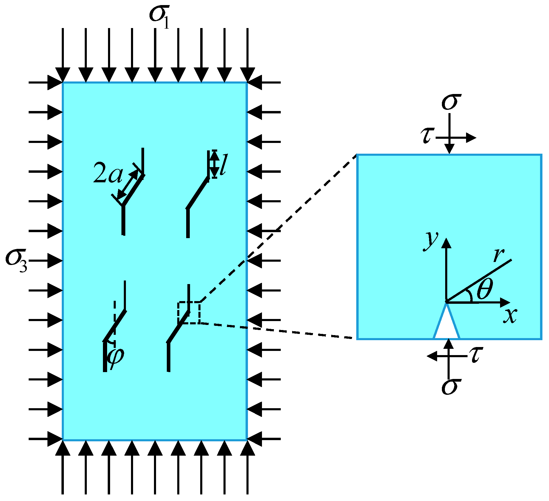
Rocks mainly comprise particles, cements, and pores. The particles stack into the skeleton, the main stress-bearing component of the rock structure. Due to the weak cementation ability of the cement, the spatial structure formed by the particles bonded by the cement is prone to damage and failure under stress. Pores randomly distributed in the stacking space of the particles weaken the bond between the particles [31]. Thus, the phenomenological theory divides the mesoscopic rock structure into intact rock unit cells (particles), crack propagation damage unit cells (cement), and pore unit cells (pores), which are randomly distributed inside the rock. The generalized model of the mesoscopic rock structure is shown in Figure 1.
Since the pore unit cells undergo free deformation under load, their load-bearing ability is ignored. Thus, the load on the rock during deformation is borne by intact rock unit cells and crack propagation damage unit cells. The stress model of the mesoscopic rock structure is shown in Figure 2.
Assuming that the unit cell deformation is coordinated within the rock under load, the following can be derived from the static equilibrium relationship between the unit cells shown in Figure 2 [32]:
σ A 0 = σ s A 1 + σ p A 2
where σ is the nominal stress of the rock, σ s is the effective stress of the intact rock unit cells, σ p is the effective stress of the crack propagation damage unit cells, A 0 is the total stressed area of the unit cells, A 1 is the stressed area of the intact rock unit cells, and A 2 is the stressed area of the crack propagation damage unit cells.
Based on the relationship between the areas of the unit cells in Figure 2, we have:
A 0 = A 1 + A 2 + A 3
where A 3 is the stressed area of the pore unit cells.
Based on the geometric damage theory, one has:
D 0 = A 3 A 0
D 1 = A 2 A 0
where D 0 is the rock pore damage, i.e., the initial damage of the rock, and D 1 is the rock crack propagation damage.
Substituting Equations (2)–(4) into (1) yields:
σ = σ s ( 1 D 0 D 1 ) + σ p D 1
According to Equation (5), the principal stress of the rock with cracks under load can be expressed as follows:
σ 1 = σ 1 s ( 1 D 0 D 1 ) + σ 1 p D 1
σ 3 = σ 3 s ( 1 D 0 D 1 ) + σ 3 p D 1
The intact rock unit cells can be considered an ideal elastic material, and their stress–strain values follow a linear elastic relationship. Thus:
σ 1 s = E ε 1 + 2 ν σ 3 s
where E and ν are the elasticity modulus of intact rock unit cells and Poisson’s ratio of intact rock unit cells, and ε 1 is the axial strain of the rock.
The rock damage constitutive equation can be derived from Equations (6)–(8) as:
σ 1 = ( 1 D 0 D 1 ) E ε 1 + 2 ν σ 3 + D 1 ( σ 1 p 2 ν σ 1 p )
Since σ 3 = 0 under uniaxial compression, and σ 3 p = 0 according to Equation (7), then Equation (9) can be simplified into:
σ 1 = ( 1 D 0 D 1 ) E ε 1 + D 1 σ 1 p
According to the literature [33], the relationship between rock stress and crack propagation can be expressed as:
σ 1 p ( l ) = σ 3 c 3 + C 2 ( c 1 + c 2 ) K I C / π a C 1 ( c 1 + c 2 )
where
c 1 = π 2 ( l / a + β ) 3 / 2
c 2 = 2 ( π α ) 2 l / a D 0 2 / 3 1 + l / ( α a ) 2
c 3 = 2 l / a / π
C 1 = π β / 3 1 + μ 2 μ
C 2 = C 1 1 + μ 2 + μ / 1 + μ 2 μ
K I C is the fracture toughness of the crack, α = cos φ , φ is the initial crack angle, β is a correction factor, a is the initial crack radius, l is the crack propagation length, and μ is the rock interface friction factor.
The actual stress of the crack propagation damage unit cells under uniaxial compression can be obtained from Equation (11):
σ 1 p ( l ) = K I C B 2 π a 2 η
where the pulling direction is defined as positive, and:
B 2 = μ sin 2 φ μ cos 2 φ sin φ 2
η = π l + β a 3 / 2 + 2 l / π S π l + α a 2 1
S = π 1 / 3 3 / 4 N V 2 / 3
where N V = N A / V is the number of cracks per unit volume, and S is the average area of the interface of a single crack after propagation.

3. Damage Evolution Equation

The rock damage accumulation under load is the result of crack propagation evolution. As shown in Figure 3 the crack propagation model of the compression failure process of rocks. The far-field stress exerts on the crack surface a normal stress and a tangential stress. The normal stress provides the interfacial friction, preventing further crack propagation. As the shear stress overcomes the interfacial friction, the crack interface exhibits slippage. As the stress increases, the stress intensity factor K I at the crack tip grows. If it reaches the fracture toughness K I C , the crack propagates from the tip.
According to the crack propagation stress model in Figure 3, the stress at the crack tip in the polar coordinate system can be established as:
σ x = 1 2 π r cos θ 2 ( 1 sin θ 2 sin 3 θ 2 ) K I σ y = 1 2 π r cos θ 2 ( 1 + sin θ 2 sin 3 θ 2 ) K I τ x y = 1 2 π r sin θ 2 cos θ 2 cos 3 θ 2 K I
where r is the polar radius, θ is the polar angle, σ x , σ y , and τ x y are the stresses at the crack tip in the rectangular coordinate system, and K I is the stress intensity factor at the crack tip.
Assuming that the fracture of the rock material obeys the Mohr-Coulumb criterion, the principal stress can be calculated as:
σ 1 = 1 2 ( σ x + σ y ) + 1 2 σ x σ y 2 + 4 τ x y 2 σ 2 = 1 2 ( σ x + σ y ) 1 2 σ x σ y 2 + 4 τ x y 2 σ 3 = ν ( σ x + σ y )
Solving Equations (21) and (22) simultaneously yields:
σ 1 = cos θ 2 1 + sin θ 2 2 π r K I
Based on Equation (23), we have:
K I = 2 π r σ 1 cos θ 2 1 + sin θ 2
According to the conservation-of-energy principle, the strain energy U after rock crack propagation under external force equals the sum of the strain energy before U e crack propagation and the additional strain energy U d . Then:
U = U e + U d
According to literature [34], the strain energy after rock crack propagation is:
U = σ 1 2 V 2 E ( 1 D 1 D 0 )
where V is the unit volume of the unit cells, and E is the elasticity modulus of the intact rock unit cells.
The strain energy U e of the rock before crack propagation is:
U e = σ 1 2 V 2 E ( 1 D 0 )
According to literature [35], the elastic strain energy variation U d induced by crack propagation is:
U d = N A 1 ν 2 E a cos φ l + a cos φ K I 2 2 π r d r
N A is the number of cracks per unit volume. l is the crack propagation length. Integrating Equation (28) yields:
U d = N A 1 ν 2 E 4 π 2 σ 1 2 ( l + a cos φ ) 3 ( a cos φ ) 3 3 ( 1 + sin θ 2 ) 2 cos 2 θ 2
Substituting Equations (26), (27) and (29) into Equation (25) yields:
D 1 = 1 ( 1 D 0 ) 1 + 2 π ( 1 ν 2 ) ( 1 D 0 ) D 0 ( l a cos φ + 1 ) 3 1 1 1 + sin θ 2 2 cos 2 θ 2 D 0
According to literature [32], the crack propagation length can be expressed as:
l = l lim / ( 1 + e q k ε 1 )
where l lim is the crack propagation length limit, k is the crack propagation speed, and q is the initial crack length parameter.
The initial damage variable D 0 can be expressed by the volume proportion of cracks per unit volume of the rock:
D 0 = 4 3 N A V π ( a cos φ ) 3
By substituting Equations (11), (30) and (32) into Equation (10), the rock damage constitutive equation can be obtained as follows:
σ 1 = ( 1 D 0 ) E ε 1 K IC / B 2 π a 2 η 1 + 2 π ( 1 ν 2 ) ( 1 D 0 ) D 0 ( l a cos φ + 1 ) 3 1 / 1 + sin θ 2 2 cos 2 θ 2 + 1 D 0 K IC B 2 π a 2 η
According to the findings of literature [36], the soft rock damage constitutive model is modified by introducing strain parameter ε 1 h , and the result after modification is:
σ 1 = ( 1 D 0 ) E ( ε 1 ε 1 h ) K IC / B 2 π a 2 η 1 + 2 π ( 1 ν 2 ) ( 1 D 0 ) D 0 ( l a cos φ + 1 ) 3 1 / 1 + sin θ 2 2 cos 2 θ 2 + 1 D 0 K IC B 2 π a 2 η
where
l = l lim 1 + e q k ε 1 ε 1 h
While Section 2 and Section 3 utilize established foundational relationships-such as static equilibrium, stress-crack propagation links, and crack-tip stress solutions for specific micro-element shapes—from prior literature to solve individual rock mechanics problems, our work uniquely synthesizes these elements to solve a distinct challenge: the quantitative characterization of damage evolution driven by crack propagation during rock failure. This integration and the resulting constitutive model represent a significant expansion and enrichment of existing rock damage research.

4. Model Parameter Determination and Verification

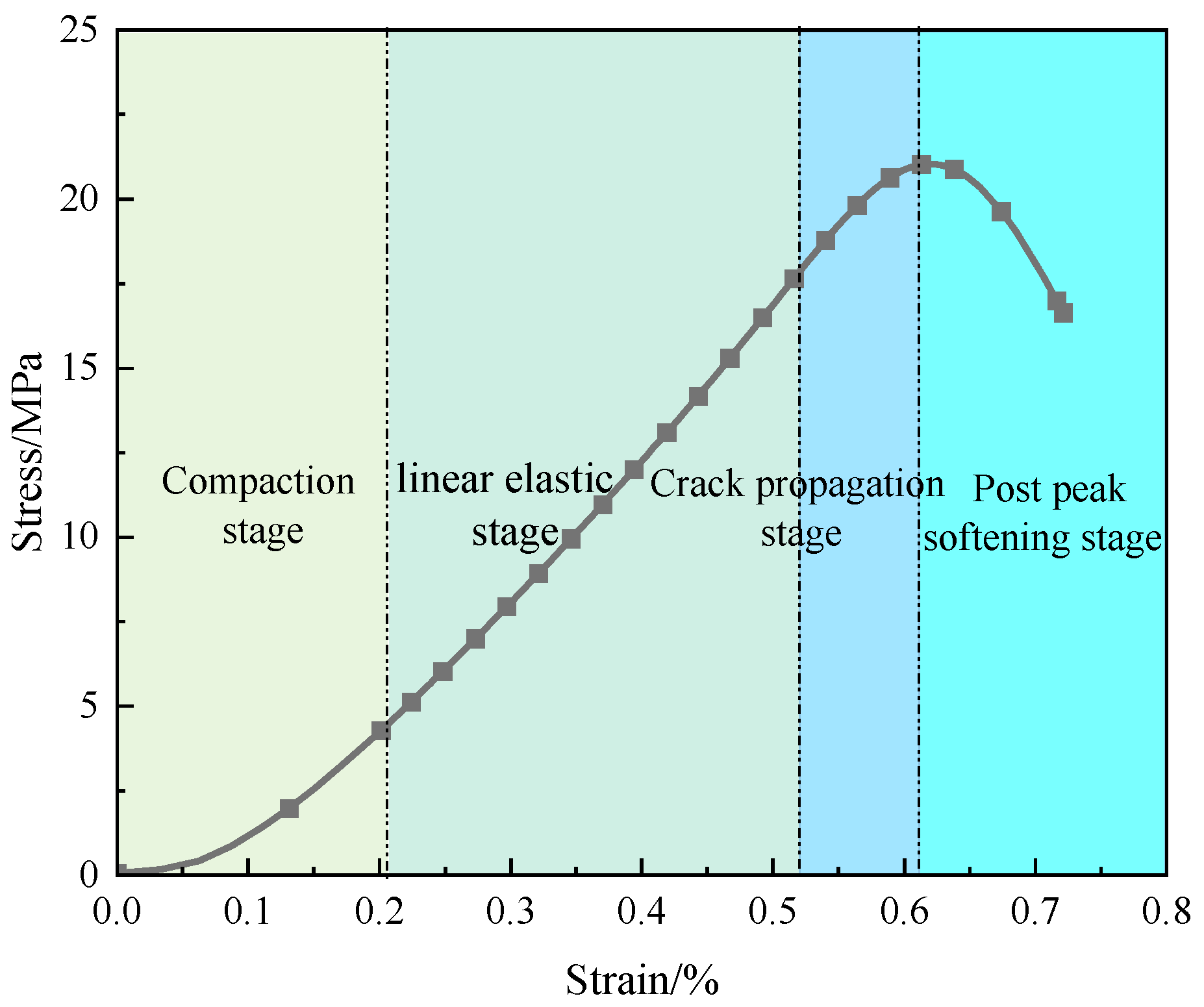
To clarify the method for determining model parameters and validate the rationality of the model, experimental stress–strain data from triaxial compression tests on moderately weathered non-layered carbonaceous mudstone under 4 MPa confining pressure were used for analysis. These specific results as shown in Figure 4 were taken directly from our previous detailed experimental investigation [32]. As comprehensively documented therein, tests were conducted on standard cylindrical specimens (R = 50 mm × H = 100 mm) under a controlled axial loading rate of 0.5–1.0 MPa/s.

4.1. Model Parameter Determination

4.1.1. Strength Parameters

The elasticity modulus E and Poisson’s ratio ν can be determined by rock compression tests. K I C can be derived from rock three-point bending tests. k can be obtained via subcritical crack propagation experiments.

4.1.2. Strain Parameters

If considering the strain produced by pore compression closure during the compaction stage, the rock strain is divided into the rock particle strain and the pore strain. Then, the pore strain under uniaxial compression can be calculated as:
ε 1 h = ε 1 σ 1 E
where ε 1 h is the strain produced by pore compaction closure when the rock is under load, which will not change after the compaction stage.
Based on Equation (36) and the uniaxial compression test results, the strain generated by pore compaction closure can be calculated, as shown in Figure 5.
The fitting formula for the strain generated by pore compaction closure is:
ε 1 h = 0.00103 0.001114 exp 1284.42566 ε 1

4.1.3. Initial Damage

The initial damage of the rock can be calculated according to the geometric damage theory as follows:
D 0 = A 3 A 0 = n A 0 A 0 = n
where n is the initial porosity of the rock, which can be measured through low-field Nuclear Magnetic Resonance (NMR) Spectroscopy tests.

4.1.4. Mesoscopic Crack Parameters

In the framework of mesoscopic mechanics homogenization, to simplify calculations, we assume that the equivalent crack propagation angle is taken as 45°. If the stress intensity at the crack tip exceeds the fracture toughness of the crack [32]. Then:
σ 1 c i = ( 1 + μ 2 ) 1 / 2 + μ ( 1 + μ 2 ) 1 / 2 μ σ 3 3 ( 1 + μ 2 ) 1 / 2 μ K I c π a
Using the method proposed by literature [37] the functional relationship between the crack initiation stress under triaxial compression and confining pressure can be determined, which can be substituted into Equation (31) to determine the interface friction factor μ and the initial equivalent radius a of the homogenized cracks of the rock.
Rock cracking is assumed to follow the Mohr-Coulumb criterion. Since sin ( 2 β ) = cos ϕ and cos ( 2 β ) = sin ϕ on the failure surface, the Mohr-Coulomb criterion can be written as:
σ 1 = 2 c cos ϕ + σ 3 ( 1 + sin ϕ ) 1 sin ϕ
where c is the cohesion, and ϕ is the internal friction angle.
Substituting Equation (40) into (23) yields:
2 c cos ϕ + σ 3 ( 1 + sin ϕ ) 1 sin ϕ = cos θ 2 1 + sin θ 2 2 π r
where the crack initiation angle θ is determined according to the minimum deviatoric strain invariant J 2 criterion. Since fracture is most likely to occur when the volume strain energy of the rock exceeds the shape strain energy, we have the following:
J 2 θ = 0
and
2 J 2 2 θ > 0
The crack initiation angle derived is:
θ = 0
The initial crack length parameter q can be solved by substituting ε 1 = 0 into Equation (35):
q = ln ( l lim l 1 )
According to the crack propagation length limit proposed by [32]:
l lim = 3 4 π N V 1 / 3 α a
where l is not 0 when ε 1 = 0 . Preferably, it can be set to l = 0.001 to characterize the length of the original crack propagation population. It can be substituted into Equation (39) to derive q .

4.2. Model Validation

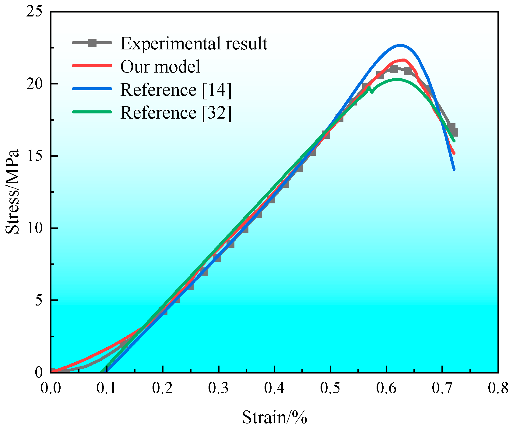
The parameters of the meso-mechanical rock damage model determined using the above methods are summarized in Table 1. The validation results, presented in Figure 6, demonstrate striking agreement between the stress–strain curve predicted by the proposed constitutive model and the experimentally measured curve from literature [32] for the triaxial compression failure process at 4 MPa confining pressure. This close correspondence provides strong empirical evidence supporting the model’s accuracy in capturing nonlinear mechanical behavior—including key stages of hardening, peak strength, and post-peak softening-under the specified confinement.
Figure 6 shows that compared with the literature [14] and [32] the damage constitutive model proposed in this paper is more consistent with the experimental results. In particular, it can better reflect the nonlinear characteristics of rock compaction and strain softening, thus verifying the rationality of the proposed model. Crucially, it accurately captures the nonlinear characteristics of both rock compaction and strain softening, validating the model’s physical rationality. The precise characterization of the compaction stage is essential for soft rocks (e.g., carbonaceous mudstone, shale), where initial pore collapse and microcrack closure dominate early deformation. Zhao et al. [14] employed the statistical damage theory to construct the rock damage equation and used the friction force after rock yield failure as the strength of the damage unit cells based on traditional material mechanics methods, thus introducing a certain level of subjectivity. The proposed model directly solves the fracture failure intensity of rock damage unit cells using fracture mechanics methods, thereby better characterizing the strength of the damage unit cells while embodying strict physical meanings. In addition, Li et al. [32] used the biological growth retardation model to characterize the evolution of the number of the damage unit cells after rock fracture, which effectively described the strain-softening characteristics during crack propagation. However, their model did not consider the impact of rock pore deformation, representing a limitation in characterizing the nonlinear characteristics of the rock compaction stage. This stage directly influences geohazard risks in tunnels, wellbores, and reservoirs, where accurate prediction of early-stage compressibility is essential for structural resilience. Our constitutive model addresses this by introducing a pore deformation parameter, which quantifies porosity reduction during compaction-resolving limitations in prior models while enhancing engineering relevance.

5. Model Parameter Impact Analysis

The parameters affecting the accuracy of the damage constitutive model include the strength parameter of intact rock unit cells E , the initial rock damage state parameter D 0 , the initial crack characteristic parameter a , and the mesoscopic parameters of the crack propagation damage unit cells q , k , and l lim . The gradual failure behavior of rocks is essentially the transformation of intact rock unit cells into crack propagation damage unit cells. Model parameter changes could alter the stress properties of intact rock unit cells and crack propagation damage unit cells and affect the efficiency of the transformation from intact rock unit cells to crack propagation damage unit cells. As a result, the stress–strain evolution pattern and crack propagation curve characteristics differ.

5.1. Effects of Model Parameters on the Modeled Rock Mechanical Properties

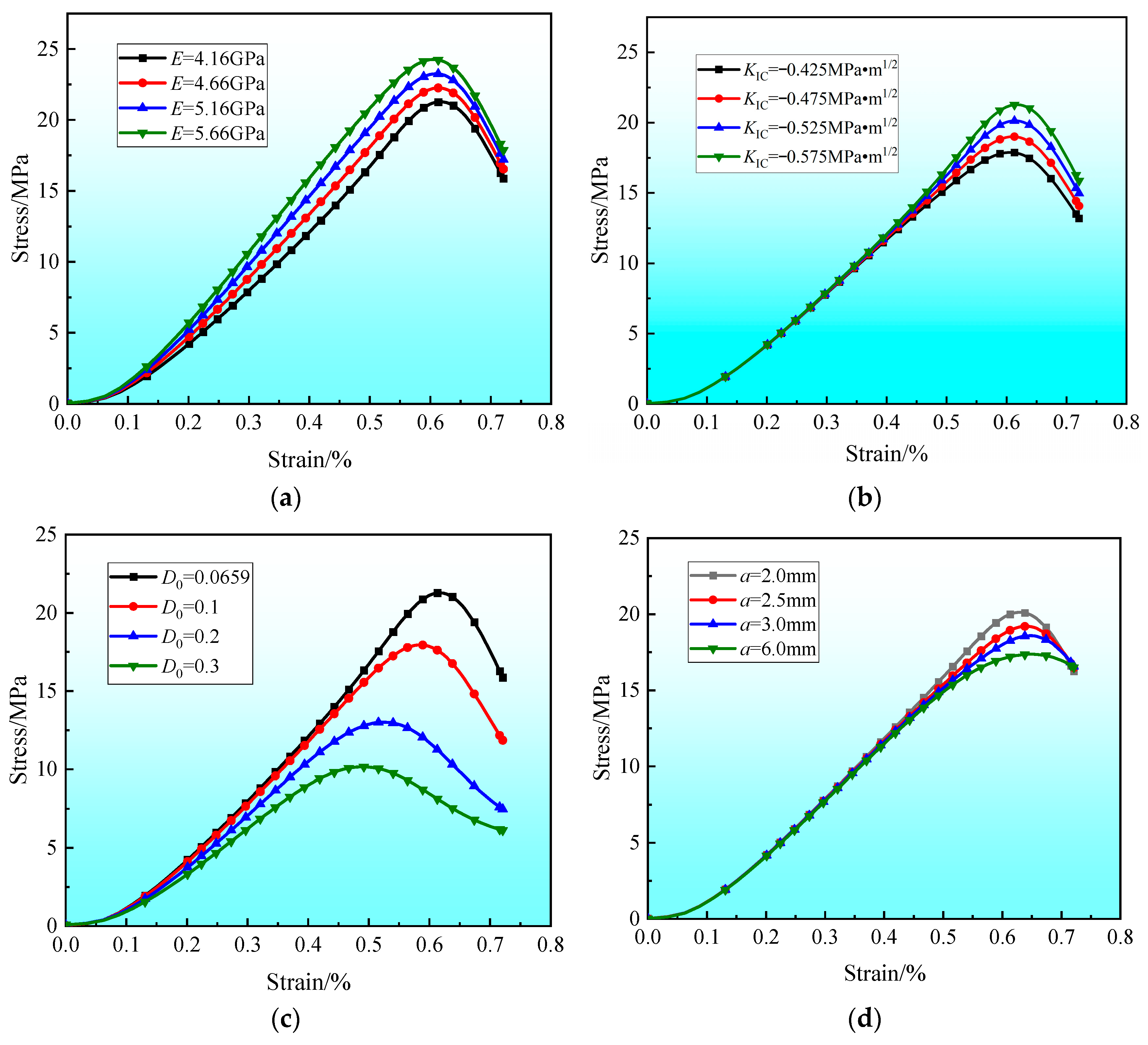
The stress–strain behavior under varying model parameters is comprehensively analyzed in Figure 7. As illustrated in Figure 7a,b, increasing the elasticity modulus and fracture toughness elevates the peak stress of the rock and results in a steeper stress–strain curve. This occurs because rocks with higher elasticity moduli and fracture toughness possess enhanced load-bearing capacity and resistance to fracture. Consequently, greater stress is required to induce fracture failure in rock unit cells, leading to increased energy accumulation prior to failure. This higher energy requirement decelerates the transformation of intact rock unit cells into crack propagation damage unit cells, thereby causing the observed steepening of the stress–strain curve.
As illustrated in Figure 7c,d, an increase in initial damage and initial crack radius leads to a reduction in the peak stress of the rock and an overall flattening of the stress–strain curve. This behavior stems from the fact that initial damage (pores and cracks) and longer initial cracks decrease the rock’s effective load-bearing area. Consequently, rock unit cells fail under lower applied stress, and less energy accumulates prior to fracture failure. This reduced energy input slows the transformation process of intact rock unit cells into crack propagation damage unit cells, thereby resulting in the observed decrease in the steepness of the stress–strain curve.
From Figure 7e,f. Under the same initial damage, the peak stress and strain of the rock increase with the increase in the initial crack length parameter but decrease with the increase in the crack propagation speed. According to the formula for crack propagation length, Equation (30), the initial characteristic parameter of the crack and the crack propagation speed can characterize the transformation efficiency of crack propagation damage unit cells. With a decreased crack propagation rate or an increased initial crack length parameter (a decreased number of crack propagation damage unit cells under the same initial damage), the transformation from intact rock unit cells to crack propagation damage unit cells decelerates. Consequently, the rock damage accumulation is small, and the mechanical properties are good, manifesting an increased peak stress.
As evident from Figure 7g,h, both the peak stress and strain of the rock increase with the initial crack dip angle but decrease with the crack propagation length limit. This behavior arises because a higher crack dip angle reduces the stress component acting along the crack propagation direction, thereby increasing the critical stress required for crack initiation and failure. Consequently, the rock exhibits greater resistance to failure, reflected in the increase in peak stress with crack dip angle. Simultaneously, a larger crack propagation length limit necessitates a greater interconnection distance between rock unit cells and requires a higher number of intact rock unit cells to transition into crack propagation damage unit cells before macroscopic fracture occurs. This accumulation of crack propagation damage unit cells accelerates the damage process within the rock, leading to the observed rapid stress drop in the post-peak stage of the stress–strain curve.

5.2. Effects of Model Parameters on the Modeled Crack Propagation Length

The effects of the initial crack length parameter and the crack propagation speed on the crack propagation length are depicted in Figure 8a,b, respectively. The effects of the initial crack length parameter and crack propagation speed on crack propagation length are presented, respectively. The crack propagation length exhibits an S-shaped increase with strain: initial growth is slow, followed by a period of rapid increase during the middle stage, and finally a gradual decrease in growth rate as it approaches the limit length, where it stabilizes. Notably, these parameters exert distinct influences on the curve. Under constant strain, crack propagation length decreases with increasing initial crack length parameter but increases with higher crack propagation speed. This occurs because a larger initial crack length parameter (implying fewer initial crack propagation unit cells) hinders the accumulation of crack propagation damage unit cells during deformation and failure at a given strain, thereby reducing the overall crack propagation length. Conversely, increased crack propagation speed accelerates the transition of intact rock unit cells into crack propagation damage unit cells, leading to a greater number of such cells and, consequently, increased crack propagation length under the same strain.
The effect of different crack propagation length limits on the crack propagation length curve is presented in Figure 8c. With the increase in the crack propagation length limit, the crack propagation length curve exhibits increased growth rates. In the early stage of crack propagation, the crack propagation length limit has a relatively small effect on the crack propagation length curve. In the late stage of crack propagation, especially when the stress reaches the peak value, the crack propagation length curve exhibits a significantly increased growth rate.

6. Conclusions

Assuming a crack propagation angle of 45°, a constitutive model for rock damage was established based on mesoscopic crack propagation by integrating phenomenological theory, fracture mechanics, and energy conservation principles. The main conclusions are as follows:
(1)
This study constructed the rock meso-structure generalization model based on phenomenological theory and solved the effective stress of rock damage unit cells by leveraging the static equilibrium relationship between the unit cells and fracture mechanics. These methods better characterized the strength of the rock crack propagation damage unit cells.
(2)
Based on geometric damage theory and the conservation-of-energy principle, we proposed to characterize rock damage by using the crack propagation length, thus providing a new idea for the quantitative study of rock crack propagation damage evolution.
(3)
Based on damage theory and meso-mechanics, we built a rock damage constitutive model upon mesoscopic crack propagation. The validation analysis showed that the proposed model could better reflect the mechanical behavior of the rock during crack propagation, and the model parameters had clear physical meaning.
(4)
The crack propagation length exhibits an S-shaped increase trend with the strain. Under the same strain, an increased initial crack length parameter, a decreased crack propagation speed, and an increased crack propagation length limit led to increased rock crack propagation length.

Author Contributions

S.L.: Methodology, Experiment, Data curation, Visualization, Writing—original draft, Writing—review and editing, Funding. H.Y.: Methodology, Supervision, Writing—review and editing. Y.L.: Conceptualization, Writing—review and editing. X.L.: Data curation, Writing—review and editing. J.T.: Methodology, Writing—review and editing. Y.G.: Methodology, Writing—review and editing. Q.L.: Visualization, Writing—review and editing. Y.S.: Data curation, Writing—review and editing, Funding. X.W.: Experiment, Writing—review and editing. C.M.: Writing—review and editing. All authors have read and agreed to the published version of the manuscript.

Funding

This research was funded through The Excellent Youth Project of Scientific Research Project of Hunan Provincial Department of Education (No. 24B0675), and The project was supported by Open Fund of Engineering Research Center of Catastrophic Prophylaxis and Treatment of Road & Traffic Safety of Ministry of Education (Changsha University of Science & Technology) (No. kfj230501), and Hunan Provincial Key Laboratory for Big Data Smart Application of Natural Disaster Risks Survey of Highway Engineering, Changsha University, (No. BNH2024KFB02). This research was supported by Hunan Provincial Key Laboratory of Intelligent Disaster Prevention-Mitigation, Ecological Restoration in Civil Engineering, Key investigation and application of Intelligent Disaster Prevention-Mitigation and Ecological Restoration in Civil Engineering and Hunan Provincial Key Laboratory for Big Data Smart Application of Natural Disaster Risks Survey of Highway Engineering. Supported by the construct program of applied specialty disciplinesin Hunan province (Hunan Institute Engineering).

Conflicts of Interest

The authors declare no conflict of interest.

References

  1. Zhang, Z.; Liu, X.; Zhao, K.; Liang, Z.; Gong, B.; You, X. Experimental Study on Acoustic Emission Features and Energy Dissipation Properties during Rock Shear-Slip Process. Materials 2024, 17, 4684. [Google Scholar] [CrossRef]
  2. Zhao, Q.; Zhao, Y.; Yang, T.; Wang, S. Mechanical behavior and micro-crack propagation mode of fault stick-slip under various roughness conditions. Geomech. Geophys. Geo-Energy Geo-Resour. 2025, 11, 1. [Google Scholar] [CrossRef]
  3. Yang, H.; Wei, Y.; Feng, L.; Zhang, S.; Zhang, X.; Liang, P. Study on the influence of non-bedding fissures on the instability and failure of anti-dip bedding rock slopes. Bull. Eng. Geol. Environ. 2025, 84, 143. [Google Scholar] [CrossRef]
  4. Wang, Z.; Lin, H.; Feng, X.; Yang, C.; Ou, K.; Chen, Y. Fracture characteristics and damage mechanisms of heat-treated sandstone with combined hole-joint flaws under uniaxial compression. Theor. Appl. Fract. Mech. 2025, 136, 104845. [Google Scholar] [CrossRef]
  5. Ketan, A.; Tanusree, C.; Seshagiri, R. Experimental Study on Stiffness Degradation of Rock Under Uniaxial Cyclic Sinusoidal Compression Loading. Rock Mech. Rock Eng. 2019, 52, 4785–4797. [Google Scholar] [CrossRef]
  6. Zhang, J.; Kikumoto, M.; Yasuhara, H.; Ogata, S.; Kishida, K. Modeling the shearing behavior of discontinuous rock mass incorporating dilation of joint aperture. Int. J. Rock Mech. Min. Sci. 2022, 153, 105101. [Google Scholar] [CrossRef]
  7. Alessio, G.; Matteo, O.; Marco, P.; Michael, B.; Ana, I.; Nick, C.; Vincent, T. Large deformation numerical assessment of rock anchor response under axial loading for offshore renewable energy applications. Comput. Geotech. 2024, 173, 106563. [Google Scholar] [CrossRef]
  8. Mousumi, M.; Giang, D.; Arash, M.; Ha, H.; Luming, S.; Abbas, E.; Federico, M. Capturing pressure- and rate-dependent behaviour of rocks using a new damage-plasticity model. Int. J. Impact Eng. 2017, 110, 208–218. [Google Scholar] [CrossRef]
  9. Liu, W.; Yin, S.; Thanh, H.; Soltanian, M.; Yu, Q.; Yang, S.; Li, Y.; Dai, Z. Advancements and development trend in statistical damage constitutive models for rock: A comprehensive review. Nat. Hazards 2025, 121, 3703–3744. [Google Scholar] [CrossRef]
  10. Gu, Q.; Zhang, Q.; Dai, W.; Quan, X.; Ye, S.; Li, T. A novel statistical damage constitutive model of rock joints considering normal stress and joint roughness. Int. J. Damage Mech. 2025, 34, 326–351. [Google Scholar] [CrossRef]
  11. Yang, L.; Wu, B.; Xu, Y.; Fu, Y.; Xia, K. Damage Evolution During Rock Dynamic Compression Revealed by Wavelet Analysis of Acoustic Emission Signals. Rock Mech. Rock Eng. 2023, 57, 1527–1535. [Google Scholar] [CrossRef]
  12. Chen, J.; Che, A.; Wang, L. Cumulative damage evolution rule of rock slope based on shaking table test using VMD-HT. Eng. Geol. 2023, 314, 107003. [Google Scholar] [CrossRef]
  13. Zhang, Z.; Song, Z.; Lai, J.; Qiu, J.; Cheng, Y.; Zhang, J. Critical slowing down precursor information for the acoustic emission response characteristics of defective tuffs. Theor. Appl. Fract. Mech. 2024, 129, 104220. [Google Scholar] [CrossRef]
  14. Zhao, H.; Zhang, C.; Cao, W.; Zhao, M. Statistical meso-damage model for quasi-brittle rocks to account for damage tolerance principle. Environ. Earth Sci. 2016, 75, 862–873. [Google Scholar] [CrossRef]
  15. Xie, S.; Lin, H.; Wang, Y.; Chen, Y.; Xiong, W.; Zhao, Y.; Du, S. A statistical damage constitutive model considering whole joint shear deformation. Int. J. Damage Mech. 2020, 29, 988–1008. [Google Scholar] [CrossRef]
  16. Chen, Y.; Tang, X.; Xu, L.; Du, X.; Wang, S.; Tomás, M.; Azzam, R. Comparative study of multiple statistical damage mechanics models for rock behaviors under high temperature. Constr. Build. Mater. 2024, 447, 138049. [Google Scholar] [CrossRef]
  17. Ru, W.; Hu, S.; Zhou, A.; Luo, P.; Gong, H.; Zhang, C.; Zhou, X. Study on Creep Characteristics and Nonlinear Fractional-Order Damage Constitutive Model of Weakly Cemented Soft Rock. Rock Mech. Rock Eng. 2023, 56, 8061–8082. [Google Scholar] [CrossRef]
  18. Yu, X.; Zuo, J.; Mao, L.; Li, Y.; Yang, L. Crack propagation behavior failure prediction of rocks with non-parallel conjugate flaws: Insights from the perspective of acoustic emission and DIC. Theor. Appl. Fract. Mech. 2024, 134 Pt A, 104709. [Google Scholar] [CrossRef]
  19. Zhang, W.; Ma, Q.; Liu, X.; Wang, E.; Xie, W.; Song, D. Study on crack propagation mechanism and acoustic-thermal sensitivity analysis of pre-cracked weakly cemented rock. Theor. Appl. Fract. Mech. 2024, 133 Pt B, 104619. [Google Scholar] [CrossRef]
  20. Kolawole, O. Mechanistic Study of Microbial Altered Properties in Dolostones. Rock Mech. Rock Eng. 2022, 56, 1099–1111. [Google Scholar] [CrossRef]
  21. Liu, B.; Liu, Q.; Liu, X.; Liu, Q.; Wang, X. Mechanical and microstructural characteristics and damage constitutive model of limestone under acid corrosion. J. Build. Eng. 2025, 108, 112903. [Google Scholar] [CrossRef]
  22. Sarah, W.; Nicolas, F.; Edward, A.; Mark, K.; David, B.; Mohammad, S. Coupled micro-computed tomography and micromechanical experiment on the failure of discontinuous porphyry rock. Int. J. Rock Mech. Min. Sci. 2025, 194, 106180. [Google Scholar] [CrossRef]
  23. Shao, Y.; Yang, J.; Kim, J.; He, C.; Song, J.; Yin, H.; Leem, J. Strain localization-controlled rock failure using digital volume correlation technology: In situ compression tests on 3D-printed rock-like samples with a single initial flaw. J. Rock Mech. Geotech. Eng. 2025, 17, 4329–4348. [Google Scholar] [CrossRef]
  24. Ryan, C. Consistent linearization of micromorphic continuum theories. Math. Mech. Solids 2025, 30, 1366–1392. [Google Scholar] [CrossRef]
  25. Li, A.; Deng, H.; Xiao, Y. Study of the Damage Evolution Process and Micromechanics Constitutive Model of Microcrystalline Limestone under Periodic Blasting Load. J. Mater. Civ. Eng. 2023, 35, 225–236. [Google Scholar] [CrossRef]
  26. Shi, Z.; Li, J.; Wang, J.; Chen, J.; Lin, H.; Cao, P. Experimental and numerical study on fracture characteristics and constitutive model of sandstone under freeze-thaw-fatigue. Int. J. Fatigue 2023, 166, 107236. [Google Scholar] [CrossRef]
  27. Tan, H.; Li, J.; Shi, Z.; Wang, M.; Wang, J.; Li, J. Damage evolution and failure characteristics of red sandstone with prefabricated crack under coupled dry-wet cycle-fatigue loading. Int. J. Fatigue 2023, 175, 107751. [Google Scholar] [CrossRef]
  28. Rong, G.; Huang, K.; Zhou, C.; Wang, X.; Peng, J. A new constitutive law for the nonlinear normal deformation of rock joints under normal load. Sci. China Technol. Sci. 2012, 55, 555–567. [Google Scholar] [CrossRef]
  29. Tang, H.; Zhu, M. Micro damage mechanics-based exponential power law acceleration of microscale damage and time-dependent crack propagation. Eng. Fract. Mech. 2020, 229, 106930. [Google Scholar] [CrossRef]
  30. Zhang, A.; Xie, H.; Zhang, Z.; Zhang, R.; Li, C.; Gao, M.; Ren, L.; Xie, J. Mechanical responses in rocks with different lithologies under mining loading-unloading: An insight by energy damage and ultrasonic characterization. Rock Mech. Rock Eng. 2024, 57, 10047–10069. [Google Scholar] [CrossRef]
  31. Li, S.; Zhang, J.; Chang, J.; Yang, H.; Yue, S.; Peng, J.; Chen, K.; Li, Y.; Ren, Z.; Chen, W. Quantitative calculation of the damage of carbonaceous mudstone during uniaxial compressive failure process under dry–wet cycling. Bull. Eng. Geol. Environ. 2025, 84, 190. [Google Scholar] [CrossRef]
  32. Li, S.; Huang, Z.; Huang, K.; Li, Y.; Peng, H.; Liang, Q.; Ma, K. Study on the evolution law and quantitative characterization of micro-crack propagation in the compressive failure process of rocks. Eng. Fail. Anal. 2024, 155, 107743. [Google Scholar] [CrossRef]
  33. Ashby, M.; Sammis, C. The damage mechanics of brittle solids in compression. Pure Appl. Geophys. 1990, 133, 489–521. [Google Scholar] [CrossRef]
  34. Zhang, X.; Yang, Y.; Yang, R.; Li, J.; Chen, S.; Li, D. Study on dynamic mechanical characteristics of specimens with cavity under prestressing conditions. Eng. Fract. Mech. 2024, 312, 110602. [Google Scholar] [CrossRef]
  35. Deng, Z.; Min, J.; Jin, J.; Liu, S.; Wei, J. The macro-meso damage model for jointed rock mass under the sequential effects of freeze–thaw cycles and compressive shear load. Comput. Geotech. 2024, 174, 106644. [Google Scholar] [CrossRef]
  36. Liu, D.; He, M.; Cai, M. A damage model for modeling the complete stress-strain relations of brittle rocks under uniaxial compression. Int. J. Damage Mech. 2018, 27, 1000–1019. [Google Scholar] [CrossRef]
  37. Li, X.; Qi, C. A micro-macro dynamic compressive-shear fracture model under static confining pressure in brittle rocks. Int. J. Impact Eng. 2018, 122, 109–118. [Google Scholar] [CrossRef]
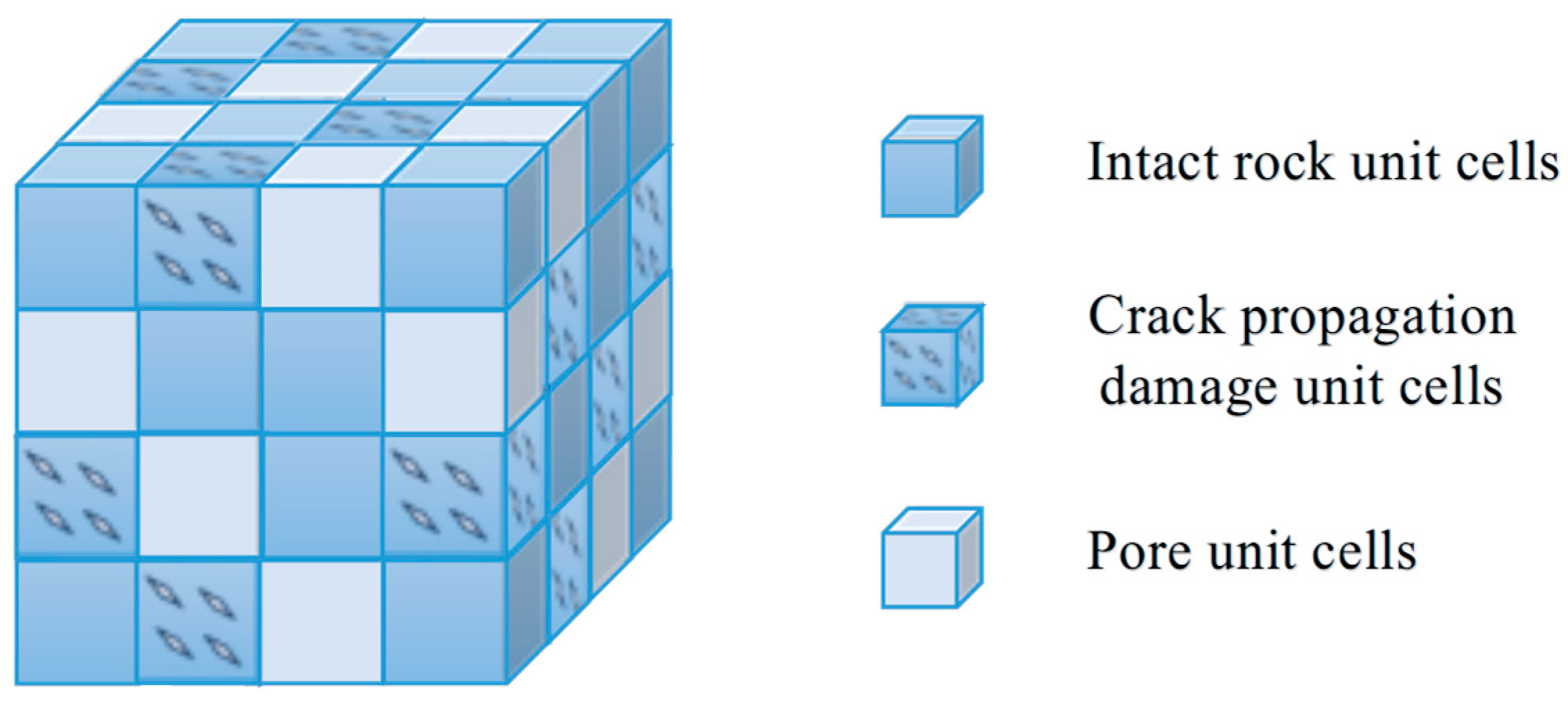
Figure 1. Rock meso-structure generalization model.
Modelling 06 00116 g001
Figure 2. Mesoscopic rock stress model.
Modelling 06 00116 g002
Figure 3. Crack propagation model.
Modelling 06 00116 g003
Figure 4. Results of triaxial compression test on carbonaceous mudstone.
Modelling 06 00116 g004
Figure 5. The strain generated by pore compaction closure in the rock under load.
Modelling 06 00116 g005
Figure 6. Comparison between experimental and theoretical model results [14,32].
Modelling 06 00116 g006
Figure 7. Effect of model parameters on the stress–strain curve: (a) Elastic Modulus E ; (b) Fracture Toughness K I C ; (c) Initial Damage D 0 ; (d) Initial Crack Radius a ; (e) Initial Crack Length Parameter q ; (f) Crack Propagation Speed k ; (g) Initial Crack Dip Angle φ ; (h) Crack Propagation Length Limit l lim .
Modelling 06 00116 g007aModelling 06 00116 g007b
Figure 8. Effect of model parameters on the crack propagation length: (a) Initial Crack Length Parameter q ; (b) Crack Propagation Speed k ; (c) Crack Propagation Length Limit l lim .
Modelling 06 00116 g008
Table 1. Parameters of the rock damage constitutive model.
E /GPa ν K IC /(MPa·m1/2) k D 0 φ μ a /mm θ β l lim /mm q
4.160.1960.57511910.0659450.262.100.160.5596.325
Disclaimer/Publisher’s Note: The statements, opinions and data contained in all publications are solely those of the individual author(s) and contributor(s) and not of MDPI and/or the editor(s). MDPI and/or the editor(s) disclaim responsibility for any injury to people or property resulting from any ideas, methods, instructions or products referred to in the content.