Article

Cost Optimization of Reinforced Concrete Section According to Flexural Cracking

by
Primož Jelušič
Faculty of Civil Engineering, Transportation Engineering and Architecture, University of Maribor, Smetanova ulica 17, 2000 Maribor, Slovenia
Modelling 2022, 3(2), 243-254; https://doi.org/10.3390/modelling3020016
Submission received: 15 April 2022 / Revised: 22 May 2022 / Accepted: 24 May 2022 / Published: 25 May 2022
(This article belongs to the Special Issue Simulation- and Modelling-Aided Structural Integrity and Safety)

Abstract

:
A series of distributed flexural cracks develop in reinforced concrete flexural elements under the working load. The control of cracking in reinforced concrete is an important issue that must be considered in the design of reinforced concrete structures. Crack width and spacing are influenced by several factors, including the steel percentage, its distribution in the concrete cross-section, the concrete cover, and the concrete properties. In practice, however, a compromise must be made between cracking, durability, and ease of construction and cost. This study presents the optimal design of a reinforced concrete cross-section, using the optimization method of mixed-integer nonlinear programming (MINLP) and the Eurocode standard. The MINLP optimization model OPTCON was developed for this purpose. The model contains the objective function of the material cost considering the crack width requirements. The crack width requirements can be satisfied by direct calculation or by limiting the bar spacing. Due to the different crack width requirements, two different economic designs of reinforced concrete sections were proposed. The case study presented in this study demonstrates the value of the presented optimization approach. A direct comparison between different methods for modelling cracking in reinforced concrete cross-sections, which has not been done before, is also presented.

1. Introduction

The study of cracking, the development of cracks under load, and the limitation of cracking must be considered in the design of reinforced concrete structures. Cracks form in flexural elements under applied loads. Since concrete has negligible tensile strength compared to steel, reinforcement is placed in the tension zone to resist the tensile force generated by the load. According to theory, crack width and crack spacing depend on the steel percentage, the distribution of steel reinforcement in the cross-section, the concrete cover, and the concrete properties. Several models have been developed for estimating the width and spacing of cracks in reinforced concrete flexural elements [1,2,3,4]. Numerical prediction of crack width and also crack propagation in concrete structures is presented in [5]. The crack width specifications requirements may be met by direct calculation, or by simply limiting the bar spacing. When calculations are made to predict maximum crack widths, they are based on the quasi-permanent combination of loads, and an effective modulus of elasticity of the concrete should be used to account for creep effects. The maximum allowable value for the crack width is given by the specifications [6,7]. Smaller crack widths are acceptable for important structural elements or in special cases where the structure retains water. The relationship between crack width and normalized reinforcement ratio, at serviceability limit state and ultimate limit state, has been analyzed, and it was confirmed that crack width is higher in beams with a low reinforcement ratio [8].
For optimal use of available materials and other resources, minimizing cost is the primary objective. The vast majority of works on cost optimization of concrete structures show significant savings [9,10,11,12,13]. The results show that it is necessary to conduct research on cost optimization of realistic structures [14,15,16]. The life cycle costs, mass, and construction costs of a floor structure, consisting of steel girders and a reinforced concrete slab, have also been analyzed using an optimization approach, but no information was provided on the crack widths in the concrete slabs [17]. Recently, the cracking modes of reinforced concrete slabs under applied bending moments have also been included in the optimal design of reinforced concrete slabs [18]. Various optimization algorithms were developed to increase computational efficiency and avoid local minima, both for individual structural elements and for the entire building. The reinforced concrete foundations of the building were optimized using both meta-heuristic algorithms [19,20,21] and deterministic algorithms [22,23]. Other important structural elements such as beams [24,25], slabs [26,27], and columns [28,29] were also optimized using deterministic and stochastic algorithms. By integrating ETABS-OAPI files into MATLAB programming, the complete 3D reinforced concrete structure was also optimized [30]. Mei and Wang [31] have provided a comprehensive review of previous research in structural optimization, including various objective functions, constraints, and algorithms. Reinforced concrete elements should be checked for ultimate and serviceability limit states, the latter including the calculation of crack width. The main weakness of previous research is that optimization models rarely consider crack width checks. Moreover, powerful machine learning methods are capable of accurately determining the properties of reinforced concrete, as Ben Seghier, et al. [32] have shown.
In order to improve the economic and mechanical performance of reinforced concrete sections, this study presents the optimization of material costs. The optimization was performed using the mixed integer nonlinear programming (MINLP) approach. For this purpose, the MINLP optimization model was developed. The model included the objective function of the material cost subjected to the crack width requirements. The crack width requirements were satisfied in the first case by direct calculation, and in the second case by limiting the bar spacing. In both cases, the cross-section with minimum material cost was determined. Since the optimization model contained integer variables, the obtained results provide an actual solution applicable in engineering practice. A direct comparison between different methods for modeling cracking in reinforced concrete cross-sections, which has not yet been carried out, will make it possible to assess whether the different methods lead to different solutions once the cross-sections are optimized. The main objective of this study was to explain the importance of the choice of crack width calculation method in optimization models for reinforced concrete design. However, it should be noted that the ultimate limit state conditions and the serviceability limit state conditions must be considered simultaneously, together with the crack width requirements in the optimal design of reinforced concrete slabs.

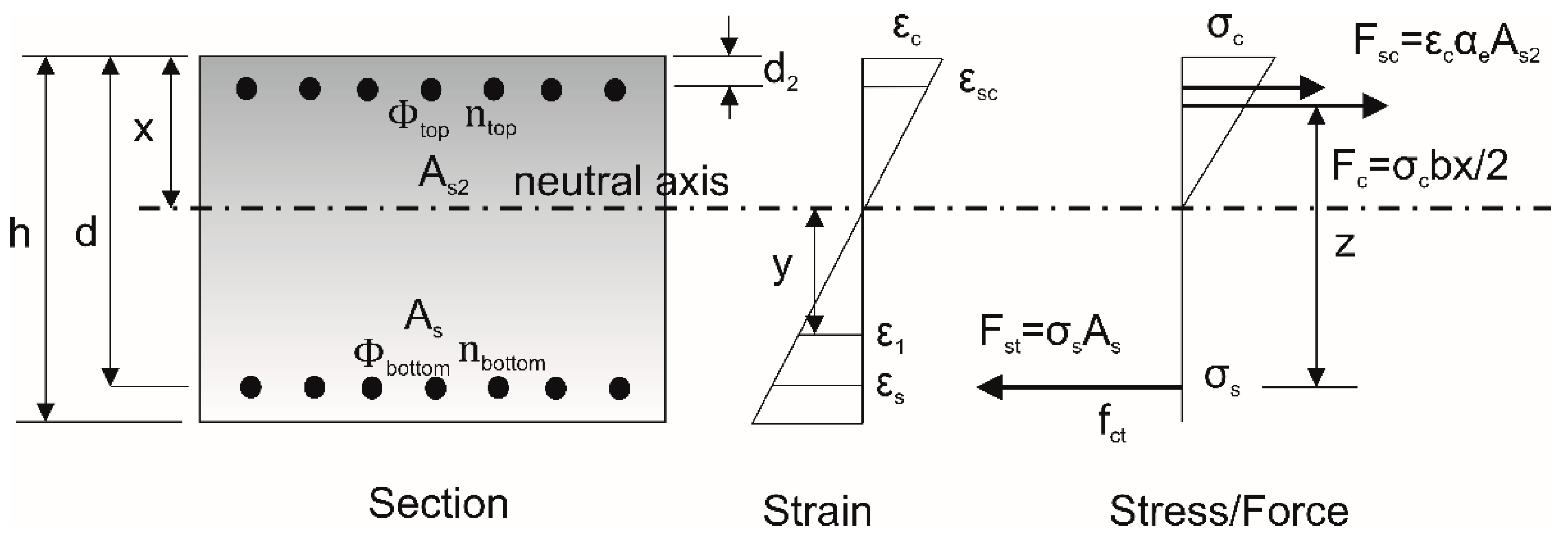
2. Mechanics of Flexural Cracking

The mechanics of flexural cracking can be illustrated by the behavior of a structural member subjected to a bending moment. A concrete slab, as shown in Figure 1, initially exhibits elastic behavior throughout the cross-section as the quasi-permanent bending moment MQP is increased. Due to the increased load, the cross-section behaves nonlinearly. In addition, the distribution of the cracks is directly related to the spacing of the steel reinforcement.
According to specifications, the crack width and the crack spacing requirements can be met by direct calculation or by limiting the bar spacing. Both methods are summarized below.

2.1. Direct Calculation of Crack Width

According to Figure 1, the strain ε1 located below the neutral axis for the distance y is calculated as:
ε 1 = y ( d x ) · ε s
where εs is defined as σs/Es, and means the average strain in the main reinforcement; σs is the steel stress in the cracked section; and Es is the modulus of elasticity of the steel reinforcement. The total width of all cracks over a unit length is equal to the strain per unit length, and is defined as:
ε 1 = y ( d x ) · σ s E s = w
where the sum of all crack widths at distance y is defined as ∑w. The total number of cracks in the unit length of the concrete slab defines the width of the individual cracks. Including the average spacing (srm), the average crack width can be calculated:
w av = w av . number   of   cracks = ε 1 ( 1 / s rm ) = s rm · ε 1
The maximum crack spacing, sr,max, can be used to design the concrete slab, considering the maximum crack width, wk. The design crack width on each plane defined by y in a structural member is given by:
w k = s r , max · ε 1 = s r , max · ( ε sm ε cm )
where wk is the design crack width; εcm is the mean strain of the concrete between cracks; and εsm is the mean strain of concrete, taking into account the effects of tensile stiffening of the concrete and shrinkage. The mean strain εsm, is less than the apparent value ε1, and (εsmεcm) is calculated by the equation:
ε sm ε cm = σ s k t f ct , eff ρ p , eff ( 1 + α e ρ p , eff ) E s 0.6 σ s E s
where the tensile stress in the steel reinforcement σs is calculated in such a way that the cracked concrete section is taken into account. By including the factor kt, the effect of load duration can also be taken into account (0.4 for long-term load, 0.6 for short-term load). Considering the most important factors affecting the crack width of a concrete section, the maximum crack spacing, sr,max, is given in Equation (6) and is based on an empirical investigation:
s r , max = 3.4 · c + 0.425 · k 1 · k 2 · ϕ / ρ p , eff
where ϕ is the size of the rebar (mm), or if different sizes of rebar are used, the average rebar size is used. The cover to the longitudinal reinforcement is defined by c, while k1 takes into account the bond properties of the reinforcing bar (1.6 for plain bars, 0.8 for high bond), and k2 the type of stress distribution, which can be assumed to be 0.5 for cracks due to bending. The effective reinforcement ratio ρp,eff is:
ρ p , eff = A s / A c , eff
where As is the area of reinforcement and Ac,eff is an effective tension area of concrete.
When the maximum crack spacing exceeds 5·(c + ϕ/2), an upper bound on the crack width can be calculated by taking:
s r , max = 1.3 · ( h x )

2.2. Control of Cracking without Direct Calculation

By specifying a minimum area for steel reinforcement, and limiting the maximum clear spacing between reinforcing bars in the longitudinal direction, cracking due to the applied load is minimized. These limitations are shown in Table 1. This ensures that the maximum crack widths in the concrete do not exceed the limit value. The stress level (σs) calculation is required to determine the maximum spacing between bars. An acceptable approximation is to take σs as:
σ s = f yk 1.15 · G k + 0.3 Q k ( 1.35 G k + 1.5 Q k ) 1 δ
where fyk is the characteristic strength of the reinforcement and δ is the ratio of the moment distribution.
To make sure that the maximum crack widths in the concrete do not exceed 0.3 mm, the relationship between the maximum clear bar spacing and the stress level is given as follows:
s l i m = 500 1.25 · σ s

3. Discrete Optimization Model OPTCON

To obtain the most rational material cost for the concrete slab, cost optimization was proposed. In contrast to the engineering practice, in which the optimization of the design parameters is carried out by some iterative successive calculation tests, in this study the exact optimization of the parameters of the reinforced concrete cross-section is discussed on the basis of mathematical programming methods [33,34].

3.1. MINLP Problem Formulation

An optimization approach of mixed integer nonlinear programming (MINLP) was used for our method. This was done because the concrete slab problem contains integer variables and nonlinear relations in both the objective function and the constraint functions, which are defined by (in)equality equations. The mathematical representation of the MINLP optimization synthesis can be expressed in the following mathematical form:
M i n   z = c T y + f ( x )     subjected   to : g ( x ) 0 h ( x ) = 0 B y + C x b x X = { x | x R n , x L o x x U p } y Y = { 0 ,   1 } m
In the above mathematical formulation of the MINLP problem, the vector of continuous variables is defined as x (within the compact set X) and the vector of discrete variables is defined as y (within the compact set Y). The objective function as well as the inequality and equality constraints are determined by the functions f(x), g(x), and h(x).
The conditions that must be satisfied for discrete choices and structural configurations of all alternatives are formulated as By + Cxb. The objective function z is divided into two parts. The first part represents the fixed costs (cTy), and the second part represents the costs that depend on certain variables contained in f(x).
In the context of concrete slabs, variables include dimensions, cross-section characteristics, materials, stresses, etc.; binary variables are also used to select standard cross-sections. (In)equality constraints and the limits of variables formulate an exact system of load, resistance, and stress functions from mechanical analysis. In this study, an objective function was proposed, to minimize the material cost of the concrete slab.

3.2. MINLP Optimization Model

In accordance with the (MINLP) problem formulation, a MINLP optimization model OPTCON was developed. Since the model was developed in a form that allowed for the use of different input parameters, the optimization of the system could be performed for different material costs. The General Algebraic Modeling System (GAMS), which includes a language compiler and MINLP solver, was used to translate the optimization problems into computer code [35]. The proposed optimization model includes input data (constants), variables, and the cost objective function of the reinforced concrete section, subject to defined mechanical and design nonlinear and linear constraints.

3.2.1. Input Data

The input data were design and economic data (constants) for optimization. The design data (constants) included the compressive strength of the concrete fck (MPa), the tensile strength of the steel fyk (MPa), the applied moment M (kNm), the maximum bar spacing smax (mm), the minimum bar spacing smin (mm), the concrete cover ccov (mm), the modulus of elasticity of the concrete Ecm (GPa), the modulus of elasticity of steel Es (GPa), the modular ratio αe (-), the density of steel ρ (kg/m3), the mean concrete strength at cracking fcm (MPa), the mean concrete tensile strength fct (MPa), the design crack width wk (mm), the cost of concrete Ccon (€/m3), and the cost of steel Csteel (€/kg).

3.2.2. Variables

The thickness of the concrete slab h (mm), the bottom bar diameter φbottom (mm), the top bar diameter φtop (mm), the number of bottom bars nbottom (-), and the number of top bars ntop (-) are given as variables in the optimization model OPTCON; see Figure 1. In order to obtain a reinforced concrete cross-section that is applicable in practice, discrete values of the variables were assigned; see Table 2.

3.2.3. Cost Objective Function

The objective function included the material cost of the reinforced concrete section COSTS (EUR); see Equation (11):
COS TS = ( b · h · 1 ) / 1000000 · C c o n + ( π · ϕ b o t t o m 2 · n b o t t o m / 4 + π · ϕ t o p 2 · n t o p / 4 ) · 1 / 1000000 · ρ s t e e l · C s t e e l
The objective function COST included the thickness of the concrete slab, the diameter of the bottom bars, the diameter of the upper bars, the number of bottom bars, and the number of top bars, which depend on the (variable) cost. The material costs for concrete and steel depend on the material properties. The coefficients Ccon and Csteel were therefore defined.

3.2.4. Mechanical Inequality Constraints

The study was concerned with the maximum crack width that can be expected to be exceeded with an acceptably low probability. For design purposes, the maximum crack width, wk, can be related to the maximum spacing, sr,max.
According to the Eurocode standards, three conditions in the form of three inequality constraints (Equations (12)–(14)) needed to be defined and entered into the OPTCON optimization model:
  • Condition 1: The maximum crack width must be limited to an acceptable value.
  • Condition 2: The compressive stress in the concrete must be limited to the design compressive concrete.
  • Condition 3: The design tensile stress in the steel must be limited to the design tensile strength of the steel.
In this way, Condition 1 is verified by Equation (12), according to which the design crack width wk (mm) must not exceed the maximum crack width wlim (mm):
w k w l i m
where:
w k = s r , max · ( ε sm ε cm )
Condition 2 is satisfied if the calculated design normal stress in concrete σc (MPa) is less than the design concrete compressive strength fcd (MPa); see Equation (13):
σ c f c d
where:
σ c d = M ( b x c ( d x c 3 ) / 2 + ( α e 1 ) A s 2 ( d d 2 ) ( x c d 2 ) / x c )
x c = ( A s α e A s 2 ( α e 1 ) + ( ( A s α e + A s 2 ( α e 1 ) ) 2 2 b ( A s α e d A s 2 d 2 ( α e 1 ) ) ) 1 2 ) b
f c d = 0.6 · f c k
When Condition 3 is considered, the calculated design stress in the tensile steel σs (MPa) is less than a design steel tensile strength fyd (MPa); see Equation (14):
σ s f y d
where:
σ s = σ c d · α e · ( d x ) x
f y d = 0.8 · f y k
When controlling cracking without direct calculation, Equation (15) limits only the spacing of the bars:
b n b o t t o m · ϕ b o t t o m n b o t t o m 500 1.25 f y k 1.15 · 1.35 · 1 δ

3.2.5. Design (in)Equality Constraints

The design (in)equality constraints determined the dimensions of the concrete slabs that needed to be calculated for the different discrete values of the variables. The reliability of the system depends on several geometric parameters, such as the thickness of the concrete slab h (mm), the bottom bar diameter φbottom (mm), the top bar diameter φtop (mm), the number of bottom bars nbottom (-), and the number of top bars ntop (-).
The thickness of the concrete slab h (mm) is limited; see Equation (16):
h L O h h U P
The bottom bar diameter φbottom (mm) varies between its lower and upper limits; see Equation (17):
ϕ b o t t o m L O ϕ b o t t o m ϕ b o t t o m U P
The constraint (Equation (18)) defines the limits for the top bar diameter φtop (mm):
ϕ t o p L O ϕ t o p ϕ t o p U P
The number of bottom bars nbottom (-) is defined by Equation (19):
n b o t t o m L O n b o t t o m n b o t t o m U P
The number of top bars ntop (-) is defined by Equation (20):
n t o p L O n t o p n t o p U P

4. Numerical Example

To interpret the proposed optimization approach, this study presents a numerical example of MINLP optimization of the material cost of a concrete slab. The optimization model presented above was developed in a general form so that an optimal design for a concrete slab can be determined for any project data (e.g., bending moment, concrete of strength class, steel strength, etc.). In order to obtain the optimal material cost and designs of the concrete slab, MINLP optimization was performed for the design parameters defined in Table 3. The concrete slab was subjected to a uniform moment of 100 kNm. Concrete of strength class C30/37 and steel S500 were used. The nominal cover of the concrete was 25 mm. The optimum design variables and the calculated values can be found in Table 4. The optimum reinforced concrete cross-section is shown in Figure 2. The material cost for the reinforced concrete cross-section is lower if the direct calculation of the crack width is used. In this numerical example, the material cost was reduced by 3%. It should be noted that both reinforced concrete cross-sections are optimal, but they are subject to different crack width and crack spacing requirements.

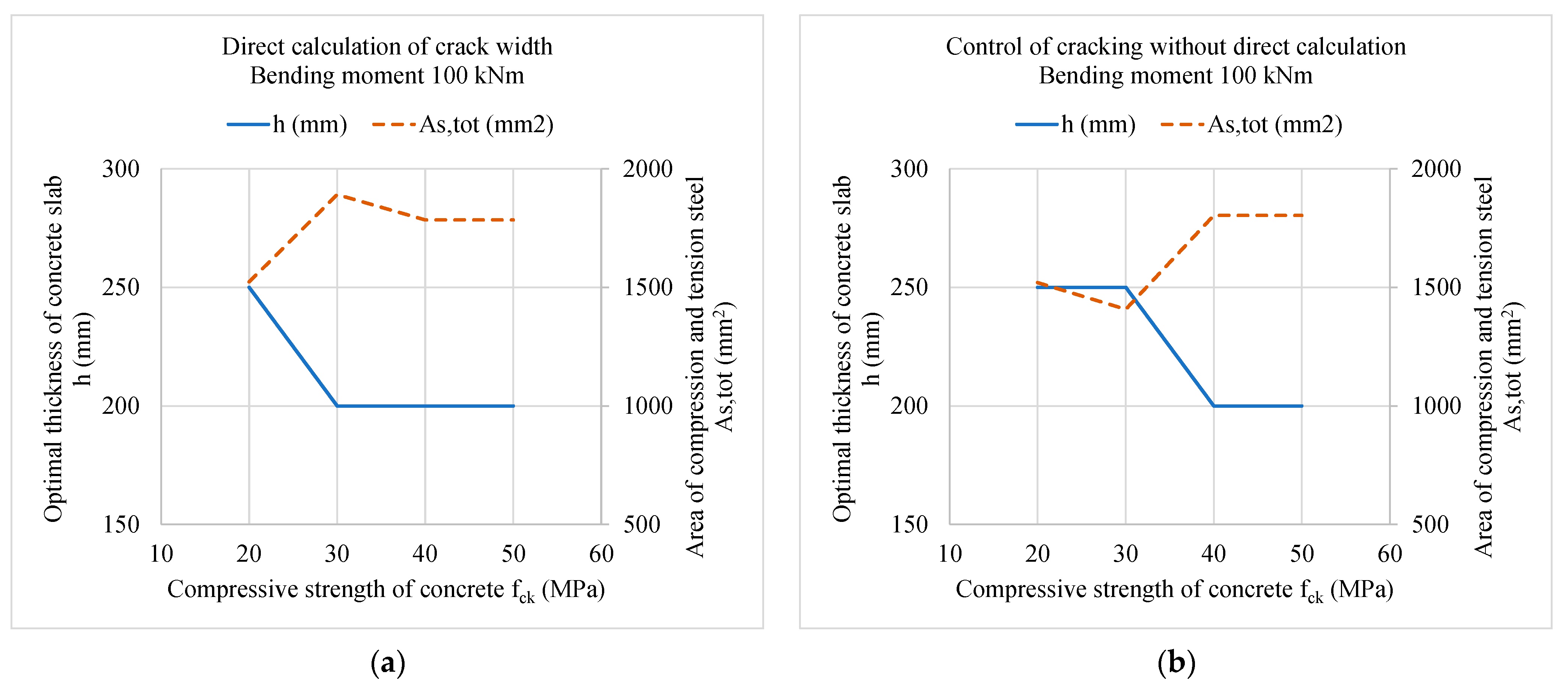
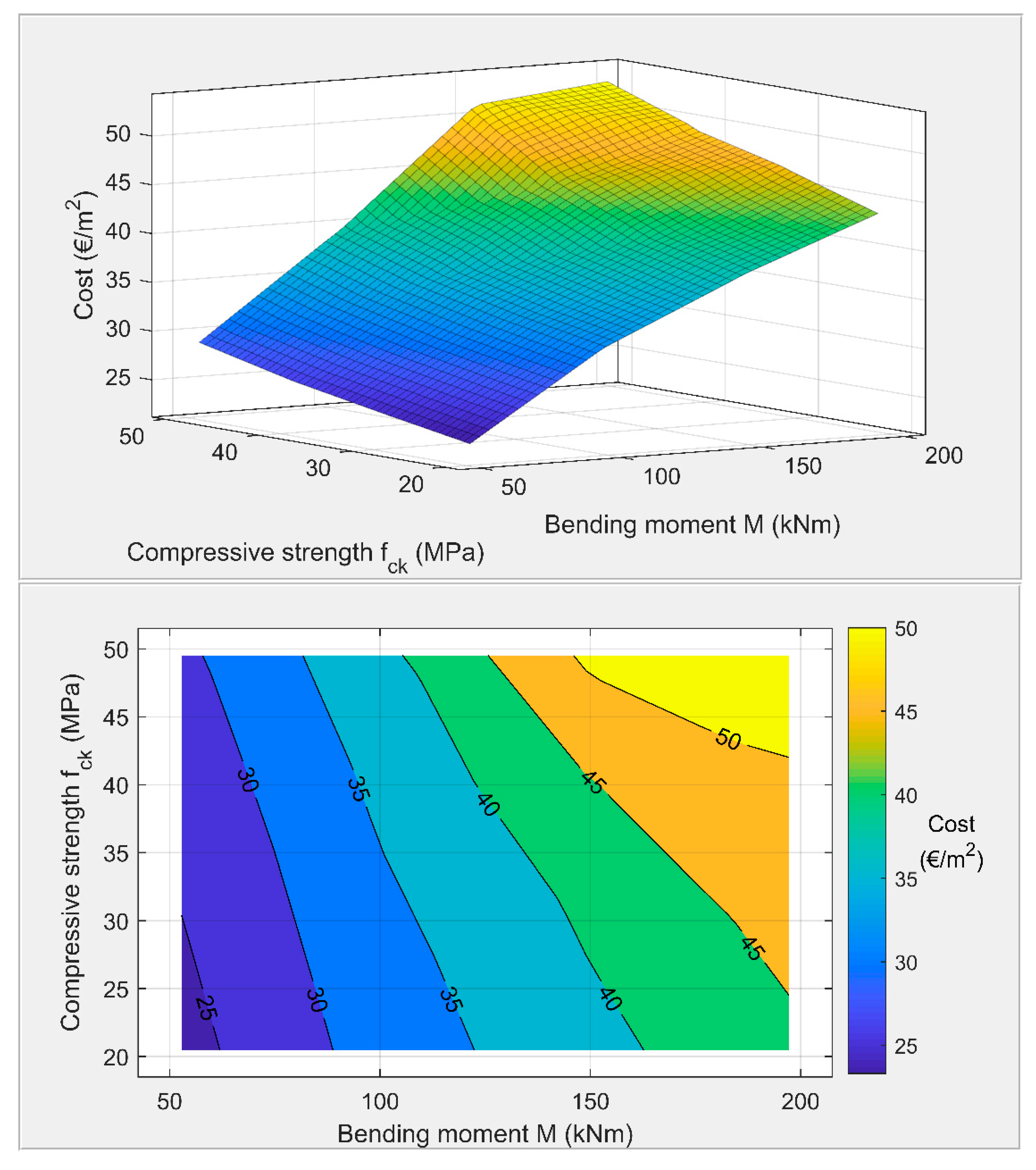
5. Parametric Analysis of an Optimally Designed Reinforced Concrete Slab

A series of optimizations of a reinforced concrete slab subjected to the crack width limit of 0.3 mm was performed for a combination of two different parameters, such as different values of the applied bending moment and strength classes of the concrete. Figure 3 shows the optimum thickness of the concrete slab h (mm) and the total area (compressive and tensile) of the steel reinforcement As,tot (mm2) for different bending moments M (kNm). The results of the optimization model, based on the direct calculation of the crack width, are shown in Figure 3a, while the results of the optimization model controlling the cracking without direct calculation are shown in Figure 3b:
The input data for the parametric analysis of an optimally designed reinforced concrete slab consisting of different concrete strength classes are given in Table 5. Figure 4 shows the optimal thickness of the concrete slab h (mm) and the total area (compressive and tensile) of the steel reinforcement As,tot (mm2) for different concrete strength classes at a bending moment of M = 100 kNm. The results of the optimization model based on the direct calculation of the crack width are shown in Figure 4a, while the results of the optimization model controlling the cracking without direct calculation are shown in Figure 4b.
The result of the parametric analysis also shows that expensive concrete with higher strength increases the cost of the concrete slab (see, Figure 5), even if a smaller slab thickness is required for the same bending moment. Figure 5 shows results based on a direct calculation of the crack width method, which was limited to wlim = 0.3 mm.

6. Conclusions

This study presents the material cost optimization of a reinforced concrete section. The optimization was performed using the mixed integer nonlinear programming (MINLP) approach. For this purpose, the MINLP optimization model OPTCON was presented, and the computer code was developed in the language compiler GAMS to solve the MINLP optimization problem. A deterministic optimization algorithm such as MINLP is faster and more efficient than other population-based algorithms in terms of convergence; population-based algorithms are more robust and can solve different types of optimization problems. The model includes the material cost objective function, which was subjected to mechanical and design constraints. Since the model was developed in a form that allowed for the use of different input parameters, the optimization of the system was performed for different material costs and different design parameters. In this way, the optimum design parameters for reinforced concrete slabs were determined, in which the conditions for crack width and crack spacing specified in the Eurocode standards were fully utilized without further resistance reserves. The generalized reduced gradient method was applied. The task of each optimization was to find the minimum material cost along with the design variables such as the thickness of the concrete slab, the bottom bar diameter, the top bar diameter, the number of bottom bars, and the number of top bars. The material cost for the concrete section was lower when the direct calculation of the crack width was used instead of limiting only the bar spacing. A direct comparison between different methods for modeling cracking in reinforced concrete cross-sections, which has not been done before, is also presented. In the case study presented, there was a small difference (by 3%) in the material cost of the reinforced concrete cross-section when the direct crack width calculation was used instead of just limiting the maximum bar spacing, but a much smaller reinforced concrete slab cross-section (by 25%) was optimal, which can be an important factor when constructing multi-story buildings. In the parametric analysis, the effects of the bending moment and the concrete strength class on the optimal design of the reinforced concrete slab were studied. In reviewing the literature on optimization models for reinforced concrete elements, it was found that crack width is rarely considered. Therefore, this study highlights this problem, and compares different methods for calculating crack width based on an optimization approach. While this study focuses only on crack width requirements, further research is needed to include all ultimate and serviceability limit states, to analyze the entire reinforced concrete structure and its optimal design. Moreover, not only the material costs but also the entire construction activity should be included in the optimization process, to demonstrate the applicability of the optimization models. The results obtained in this work are based on the Eurocode standard; the use of other specifications for crack calculation should also be investigated.

Funding

This research was funded by the Slovenian Research Agency (grant number P2-0268).

Institutional Review Board Statement

Not applicable.

Informed Consent Statement

Not applicable.

Conflicts of Interest

The authors declare no conflict of interest.

References

  1. Chi, M.; Kirstein, A.F. Flexural cracks in reinforced concrete beams. ACI J. Proc. 1958, 54, 865–878. [Google Scholar]
  2. Gergely, P.; Lutz, L.A. Maximum crack width in reinforced concrete flexural members. Am. Concr. Inst. 1968, 20, 87–117. [Google Scholar]
  3. Oh, B.H.; Kang, Y.-J. New formulas for maximum crack width and crack spacing in reinforced concrete flexural members. ACI Struct. J. 1987, 84, 103–112. [Google Scholar]
  4. Frosch, R.J. Another Look at Cracking and Crack Control in Reinforced Concrete. ACI Struct. J. 1999, 96, 437–442. [Google Scholar]
  5. Theiner, Y.; Hofstetter, G. Numerical prediction of crack propagation and crack widths in concrete structures. Eng. Struct. 2009, 31, 1832–1840. [Google Scholar] [CrossRef]
  6. EN1992-1-1 2004; CEN Eurocode 2 Design of Concrete Structures—Part 1-1: General Rules and Rules for Buildings. BSI: London, UK, 2004.
  7. ACI 318R-95 1995; ACI (American Concrete Institute) Building Code Requirement for Reinforced Concrete. ACI: Farmington Hills, MI, USA, 1995.
  8. Basri, M.; Bakar, C.; Saifulnaz, R.; Rashid, M.; Amran, M.; Jaafar, M.S.; Vatin, N.I.; Fediuk, R. Flexural Strength of Concrete Beam Reinforced with CFRP Bars: A Review. Materials 2022, 15, 1144. [Google Scholar]
  9. Brown, R.H. Minimum cost selection of one-way slab thickness. J. Struct. Div. ASCE 1975, 101, 2585–2590. [Google Scholar] [CrossRef]
  10. Jones, H.L. Minimum Cost Prestressed Concrete Beam Design. J. Struct. Eng. 1985, 111, 2464–2478. [Google Scholar] [CrossRef]
  11. MacRae, A.J.; Cohn, M.Z. Optimization of Prestressed Concrete Flat Plates. J. Struct. Eng. 1987, 113, 943–957. [Google Scholar] [CrossRef]
  12. Kanagasundaram, S.; Karihaloo, B.L. Minimum-cost design of reinforced concrete structures. Comput. Struct. 1991, 41, 1357–1364. [Google Scholar] [CrossRef]
  13. Al-Salloum, Y.A.; Siddiqi, G.H. Cost-Optimum Design of Reinforced Concrete (RC) Beams. ACI Struct. J. 1994, 91, 647–655. [Google Scholar] [CrossRef]
  14. Jelusic, P.; Kravanja, S. Optimal design of timber-concrete composite floors based on the multi-parametric MINLP optimization. Compos. Struct. 2017, 179, 285–293. [Google Scholar] [CrossRef]
  15. Jelušič, P.; Žlender, B. Optimal design of piled embankments with basal reinforcement. Geosynth. Int. 2018, 25, 150–163. [Google Scholar] [CrossRef]
  16. Waheed, J.; Azam, R.; Riaz, M.R.; Shakeel, M.; Mohamed, A.; Ali, E. Metaheuristic-Based Practical Tool for Optimal Design of Reinforced Concrete Isolated Footings: Development and Application for Parametric Investigation. Buildings 2022, 12, 471. [Google Scholar] [CrossRef]
  17. Kravanja, S.; Klanšek, U.; Žula, T. Mass, Direct Cost and Energy Life-Cycle Cost Optimization of Steel-Concrete Composite Floor Structures. Appl. Sci. 2021, 11, 10316. [Google Scholar] [CrossRef]
  18. Rady, M.; Mahfouz, S.Y.; Taher, S.E.-D.F. Optimal Design of Reinforced Concrete Materials in Construction. Materials 2022, 15, 2625. [Google Scholar] [CrossRef] [PubMed]
  19. Solorzano, G.; Plevris, V. Optimum design of RC footings with genetic algorithms according to ACI 318-19. Buildings 2020, 10, 110. [Google Scholar] [CrossRef]
  20. Kashani, A.R.; Gandomi, M.; Camp, C.V.; Gandomi, A.H. Optimum design of shallow foundation using evolutionary algorithms. Soft Comput. 2020, 24, 6809–6833. [Google Scholar] [CrossRef]
  21. Chaudhuri, P.; Maity, D. Cost optimization of rectangular RC footing using GA and UPSO. Soft Comput. 2020, 24, 709–721. [Google Scholar] [CrossRef]
  22. Jelušič, P.; Žlender, B. Optimal Design of Reinforced Pad Foundation and Strip Foundation. Int. J. Geomech. 2018, 18, 04018105. [Google Scholar] [CrossRef]
  23. Jelušič, P.; Žlender, B. Optimal design of pad footing based on MINLP optimization. Soils Found. 2018, 58, 277–289. [Google Scholar] [CrossRef]
  24. Rahmanian, I.; Lucet, Y.; Tesfamariam, S. Optimal design of reinforced concrete beams: A review. Comput. Concr. 2014, 13, 457–482. [Google Scholar] [CrossRef]
  25. Pierott, R.; Hammad, A.W.A.; Haddad, A.; Garcia, S.; Falcón, G. A mathematical optimisation model for the design and detailing of reinforced concrete beams. Eng. Struct. 2021, 245, 112861. [Google Scholar] [CrossRef]
  26. Stochino, F.; Lopez Gayarre, F. Reinforced Concrete Slab Optimization with Simulated Annealing. Appl. Sci. 2019, 9, 3161. [Google Scholar] [CrossRef] [Green Version]
  27. Ghandi, E.; Shokrollahi, N.; Nasrolahi, M. Optimum cost design of reinforced concrete slabs using cuckoo search optimization algorithm. Iran Univ. Sci. Technol. 2017, 7, 539–564. [Google Scholar]
  28. Sánchez-Olivares, G.; Tomás, A. Optimization of Reinforced Concrete Sections under Compression and Biaxial Bending by Using a Parallel Firefly Algorithm. Appl. Sci. 2021, 11, 2076. [Google Scholar] [CrossRef]
  29. De Medeiros, G.F.; Kripka, M. Optimization of reinforced concrete columns according to different environmental impact assessment parameters. Eng. Struct. 2014, 59, 185–194. [Google Scholar] [CrossRef]
  30. Aslay, S.E.; Dede, T. 3D cost optimization of 3 story RC constructional building using Jaya algorithm. Structures 2022, 40, 803–811. [Google Scholar] [CrossRef]
  31. Mei, L.; Wang, Q. Structural optimization in civil engineering: A literature review. Buildings 2021, 11, 66. [Google Scholar] [CrossRef]
  32. Ben Seghier, M.E.A.; Ouaer, H.; Ghriga, M.A.; Menad, N.A.; Thai, D.K. Hybrid soft computational approaches for modeling the maximum ultimate bond strength between the corroded steel reinforcement and surrounding concrete. Neural Comput. Appl. 2021, 33, 6905–6920. [Google Scholar] [CrossRef]
  33. Jelušič, P.; Žlender, B. Soil-nail wall stability analysis using anfis. Acta Geotech. Slov. 2013, 10, 61–73. [Google Scholar]
  34. Jelušič, P.; Žlender, B.; Dolinar, B. NLP Optimization Model as a Failure Mechanism for Geosynthetic Reinforced Slopes Subjected to Pore-Water Pressure. Int. J. Geomech. 2016, 16, C4015003. [Google Scholar] [CrossRef]
  35. Brook, A.; Kendrick, D.; Meeraus, A. GAMS, a user’s guide. ACM Signum Newsl. 1988, 23, 10–11. [Google Scholar] [CrossRef]
Figure 1. Cross-section of a reinforced slab, and corresponding strain diagram and stress block.
Modelling 03 00016 g001
Figure 2. Optimum design cross-section of a concrete slab for different crack spacing requirements (direct calculation or by limiting bar spacing).
Modelling 03 00016 g002
Figure 3. Optimum thickness of concrete slab (concrete strength class C30/37) and optimum area of steel reinforcement for different bending moments: (a) Direct calculation of crack width; (b) Control of cracking without direct calculation.
Modelling 03 00016 g003
Figure 4. Optimal thickness of concrete slab built from different strengths of concrete, and optimal area of steel reinforcement at bending moment of 100 kNm: (a) Direct calculation of crack width; (b) Control of cracking without direct calculation.
Modelling 03 00016 g004
Figure 5. The relationship between the optimum cost of a concrete slab, the bending moment, and the compressive strength class of the concrete.
Modelling 03 00016 g005
Table 1. Limitation of maximum bar spacing as a function of tensile stress in steel.
Steel Stress
σs (N/mm2)
Maximum Bar Spacing slim (mm)
wk = 0.3
160300
200250
240200
280150
320100
36050
Table 2. The values of discrete variables.
VariableAllowable Discrete Values
h (mm)100, 150, 200, 250, 300, 350, 400
ϕbottom (mm)8, 10, 12, 14, 16, 18, 20
ϕtop (mm)8, 10, 12, 14, 16, 18, 20
nbottom (-)4, 5, 6, 7, 8, 9, 10
ntop (-)4, 5, 6, 7, 8, 9, 10
h (mm)100, 150, 200, 250, 300, 350, 400
Table 3. Input data into the optimization model OPTCON.
Input NameSymbolValue
Compressive strengthfck30 MPa
Mean concrete strength at crackingfcm,t38 MPa
Mean concrete tensile strengthfct,eff2.9 MPa
Modulus of elasticity of concreteEcm32.8 GPa
Yield stress of steelfyk500 GPa
Modulus of elasticity of steelEs200 GPa
Density of steelρs7850 kg/m3
Width of concrete sectionb1000 mm
Applied moment M100 kNm
Cover of concretec25 mm
Modular ratioαe18.27
Final creep coefficientφ2.0
Minimum bar spacing smin60 mm
Maximum bar spacing smax200 mm
Moment redistributionδ1
Cost of concreteCcon95 €/m3
Cost of steel Csteel1.0 €/kg
1st case: Direct calculation of crack widthwlim0.3 mm
2nd case: Control of cracking without direct calculationslim500–1.25·σs
Table 4. Optimal design variables and calculated crack width.
Optimal Design VariablesSymbol1st Case: Direct Calculation of Crack Width2nd Case: Control of Cracking without Direct Calculation
Thickness of concrete slabh (mm)200250
Bottom bar diameterφbottom (mm)148
Top bar diameterφtop (mm)812
Number of bottom barsnbottom (-)1010
Number of top barsntop (-)78
Calculated values
Fully cracked neutral axis depthxc (mm)78.48382.516
Concrete stressσc (MPa)17.89712.608
Stress in tension steelσs (MPa)372.951386.589
Effective tension areaAc,eff (mm2)38,966.23755,325.476
Area of tension steelAs (mm2)1539.380502.655
Area of compression steelAs2 (mm2)351.858904.779
Steel-to-concrete ratio (As/Ac,eff)ρp,eff (-)0.0400.009
Max. final crack spacingsr,max (mm)145.245217.730
Average strain for crack widthεsm − εcm (μstrain)1611.9731188.591
Calculated crack widthwk (mm)0.2340.259
Material costsCOSTS (€/m2)33.84634.798
Table 5. Input data and optimum design of concrete slabs for different concrete strength classes at a bending moment load of 100 kNm.
Input NameDesign Data 1Design Data 2Design Data 3Design Data 4
M (kNm)100100100100
Strength classesC20/25C30/37C40/50C50/60
fck (MPa)20304050
fcm (MPa)28384858
fct (MPa)2.22.93.54.1
Ecm (GPa)30.032.835.237.3
Ccon (€/m3)8095110125
1st case: Direct calculation of crack width
h (mm)250200200200
φbottom (mm)1281010
φtop (mm)10141414
nbottom (-)51077
ntop (-)10799
COSTS (€/m2) 31.96133.84636.00839.008
2nd case: Control of cracking without direct calculation
h (mm)250250200200
φbottom (mm)12121212
φtop (mm)881010
nbottom (-)10101010
ntop (-)9899
COSTS (€/m2) 31.93634.79836.15639.156
Publisher’s Note: MDPI stays neutral with regard to jurisdictional claims in published maps and institutional affiliations.

