Article

Magnetron Sputter Deposition of Nanostructured AlN Thin Films

1
Department of Materials and Production, Aalborg University, 9220 Aalborg, Denmark
2
Electron Microscopy Unit, Hamburg University of Technology, 21073 Hamburg, Germany
*
Authors to whom correspondence should be addressed.
Appl. Nano 2023, 4(4), 280-292; https://doi.org/10.3390/applnano4040016
Submission received: 9 August 2023 / Revised: 11 September 2023 / Accepted: 27 September 2023 / Published: 5 October 2023
(This article belongs to the Collection Feature Papers for Applied Nano)

Abstract

:
Aluminum nitride (AlN) is a material of growing interest for power electronics, fabrication of sensors, micro-electromechanical systems, and piezoelectric generators. For the latter, the formation of nanowire arrays or nanostructured films is one of the emerging research directions. In the current work, nanostructured AlN films manufactured with normal and glancing angle magnetron sputter depositions have been investigated with scanning and transmission electron microscopy, X-ray diffraction, atomic force microscopy, and optical spectroscopy. Growth of the nanostructures was realized utilizing metal seed particles (Ag, Au, and Al), allowing the control of the nucleation and following growth of AlN. It was demonstrated how variations of seed particle material and size can be used to tune the parameters of nanostructures and morphology of the AlN films. Using normal angle deposition allowed the growth of bud-shaped structures, which consisted of pillars/lamellae with wurtzite-like crystalline structures. Deposition at a glancing angle of 85° led to a film of individual nanostructures located near each other and tilted at an angle of 33° relative to the surface normal. Such films maintained a high degree of wurtzite-like crystallinity but had a more open structure and higher roughness than the nanostructured films grown at normal incidence deposition. The developed production strategies and recipes for controlling parameters of nanostructured films pave the way for the formation of matrices to be used in piezoelectric applications.

1. Introduction

Nitrides like aluminum nitride (AlN) and gallium nitride (GaN) are interesting as piezoelectric (PZ) materials in actuators, sensors, and energy generators [1,2]. In the context of energy generation, there is a strong emphasis on autonomous self-powered systems that can harness energy for sensing and communication purposes from mechanical movements in the surroundings [3]. Here, PZ films and nanostructures play an important role as they enable the integration of the energy supply and the active electronics [4]. In particular, there is an incentive to reduce the size and optimize the power generation per volume of wearable electronics. Nanostructured PZ films are ideal for the design of compact devices. They offer the opportunity to tailor the overall elastic properties of devices to enhance their mechanical integration with the surrounding environment, thereby optimizing the piezoelectric energy conversion [5,6,7]. Furthermore, the PZ response of nanostructured films or assemblies was found to be higher than that of their bulk counterparts [8,9,10]. Depending on the size and shape of the nanostructures, the surface-to-volume ratio of atoms varies, which affects crystal lattice parameters and local electric potentials [11]. Furthermore, the conditions under which the films grow significantly impact their crystalline structure, morphology, and properties [12]. The formation of a wide range of microstructures, nanostructures and synthesis techniques were reviewed by Nersisyian et al. [13]. Several works have explored the PZ response of individual nanowires [5], arrays of wires [6], and energy generators based on arrays of wires [7]. In most cases, these nanowire-based films were grown via molecular beam epitaxy (MBE), resulting in highly crystalline structures. Advanced modes of atomic force microscopy (AFM) have been the standard characterization technique since conductive cantilever tips can deliver mechanical stress and record the electric response simultaneously [5,6,7,10]. In the group of PZ metal-nitrides, GaN nanowires have been among the most investigated, while the PZ properties of AlN nanostructures have remained less explored [12,14,15]. It was found in [15] that individual AlN nanowires could produce mV-level voltage on bending; thus, arrays of wires were considered to be promising for exploiting piezoelectricity for energy generation. In the studies by L. Jaloustre et al. [16], the piezoelectric constant d33 of MBE-grown AlN nanowires was measured to be 4.4–4.5 pV/m. However, MBE is a relatively expensive and slow method of growth.
An advantage of magnetron sputter deposition is that it is a standard industrial technique allowing high growth rates and good opportunities for variation of the chemical composition of the synthesized materials. A systematic review of reactive magnetron sputtering of AlN thin films was recently given by Mwema et al. [17]. This topic has been extensively studied over several decades, yielding a large number of publications discussing different deposition strategies for tuning the film parameters in order to reach the desired properties [18,19,20,21,22,23,24,25], including PZ properties [26,27,28]. The use of glancing angle deposition (GLAD) introduces the possibility of growing films consisting of nanorods and tuning the angle they make with the surface normal [29,30]. This enables control over the elastic properties of the nanostructured film by varying the degree of axial compression versus bending of the nanorods. Control of spatial separation of tilted AlN nanorods/nanocolumns obtained using GLAD can be advantageous for enhancing the PZ properties. This approach has been recently tested, and it was found that AlN nanostructures grown on seeded Ag nanoparticles using reactive magnetron sputter deposition can generate giant PZ response, reaching values of 20–30 pV/m, i.e., up to six times that of the previously reported constants of AlN [10].
In this work, the focus is on varying the conditions for growing AlN on seeded metal nanoparticles in order to form films with desired parameters of nanostructures and, thus, be able to tune the AlN properties. As mentioned above, similar structures were demonstrated to provide a giant piezoelectric effect [10]. Thus, optimization of the growth of nanostructured AlN films can facilitate the development of technologies towards practical applications of such PZ materials. The formation of nanostructures is promoted by the pre-deposition of metal (Al, Ag, and Au) particles of various sizes. AlN films with nanostructures of varied lengths are deposited at normal incidence and at glancing angles. Results of film growth on the substrates with/without nanoparticles are compared using scanning and transmission electron microscopy, X-ray diffraction (XRD) analysis, AFM, and optical spectroscopy.

2. Materials and Methods

The structures were grown on Si (111) substrates using reactive magnetron sputtering and e-beam deposition in a cluster system (Flextura 200; Polyteknik AS, Østervrå, Denmark). Good electrical contact at the bottom of the AlN was obtained by initially depositing a 250 nm TiN layer on Si using DC reactive magnetron sputtering at a pressure of 3 × 10 7 mbar and sample temperature of 835 °C, as described elsewhere [31]. DC sputtering was performed under a bias power of 390 W with Ar and N2 gas (both of 99.999% purity, purchased from Air Liquide Denmark A/S; Taastrup, Denmark) flows of 20 and 25 sccm, respectively, yielding a deposition rate of 0.5 nm s−1. Al and Ti sputtering targets (with 99.999 and 99.995% purities, respectively) and e-beam evaporation materials (Al, Ag, and Au with 99.999% purity) were purchased from the Kurt J. Lesker company (St. Leonards-on-Sea, UK). The sample was then transferred in situ to an e-beam deposition chamber for the growth of metal layers (Al, Ag, and Au) at a substrate temperature of 600 °C to initiate the formation of nanoparticles that should act as nucleation spots for the subsequent formation of AlN nanostructures. Continuous AlN films were also grown directly on TiN/Si substrates for comparison. AlN nanostructured and continuous films were formed both at normal incidence and at an oblique angle of 85°. The AlN layers were deposited at a substrate temperature of 200 °C, with a consistent N2/Ar gas flow ratio of 8.9 sccm/8.9 sccm, power of 300 W, and a steady processing pressure of 5 × 10⁻³ mbar in the vacuum chamber. The growth of the TiN layer, metal nanoparticles, and AlN were all carried out in situ, where the samples remained under vacuum within the deposition system for the entire procedure.
Scanning electron microscopy (SEM) studies were carried out utilizing a CrossBeam XB 1540 system from Zeiss (Jena, Germany) using an applied voltage and aperture of 10 kV and 30 μm, respectively. High-resolution transmission electron microscopy (HRTEM), scanning transmission electron microscopy (STEM), and energy-dispersive X-ray spectroscopy (EDS) were performed using a FEI Talos F200X transmission electron microscope (Thermo Fisher Scientific Inc.; Waltham, MA, USA). This microscope is equipped with a high-brightness Schottky field-emission gun (x-FEG) and a four-quadrant SDD-EDS system, which has a solid angle coverage of 0.9 srad. The measurements were performed on lamellae with a thickness of 100 nm, which were fabricated using a focused Ga+ ion beam of an FEI Helios G3 UC instrument. Using the in situ lift-out technique, these lamellae were moved to Cu lift-out grids. A protective layer of 20 nm thick carbon was coated on the sample to prevent charging during the ion milling. XRD analysis was carried out utilizing an Empyrean diffractometer from Malvern Panalytical (Malvern, UK) paired with a Cu Kα source in a Bragg–Brentano geometry at a voltage, current, and scan rate of 45 kV, 40 mA, and 0.32 °/s, respectively.
Contact-mode AFM analyses were performed using an Ntegra-Aura nanolaboratory from NT-MDT (Moscow, Russia). Commercial silicon cantilevers with a spring constant of 0.5–9.5 N/m were used for the measurements, which were carried out on areas of 2 × 2 μm2 at a frequency of 0.3 Hz and with a resolution of 512 × 512. Analyses of surface height distribution and roughness were performed utilizing Image Analysis software (NT-MDT).
Linear optical reflectance measurements were carried out using a Lambda 1050 spectrometer (Perkin Elmer; Shelton, CT, USA) with an integrating sphere and 8° incidence angle. The optical second harmonic generation (SHG) measurements were carried out with a wavelength-adjustable beam from an optical parametric oscillator (OPO). This OPO was pumped by a Nd:YAG laser with a 5 ns pulse length and a 10 Hz repetition rate. The average power impacting the sample from the OPO was of the order of 10 mW, focused on a 1 mm spot at normal incidence.

3. Results and Discussions

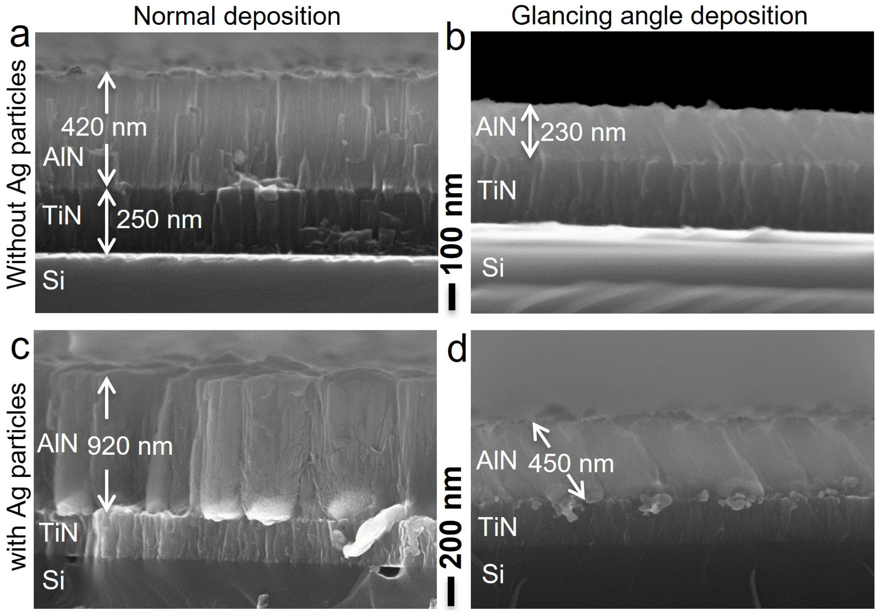
3.1. Dependence on Deposition Angle

Figure 1 shows cross-sectional SEM images of the samples with a 250 nm thick TiN layer followed by AlN grown at normal (a and c) and oblique (b and d) incidence without (a and b) and with (c and d) Ag nanoparticles. The TiN layer consists of columns approximately 100 nm in diameter. On top of this, AlN forms a columnar film for deposition without nanoparticles. In the presence of metal nanoparticles, AlN grow on them, forming individual nanostructures consisting of lamellae/pillars (as shown later by the HRTEM and STEM results). The lateral dimensions of these nanostructures depend on the initial size of the nanoparticles. With increasing length, the nanostructures make contact with each other, forming a nanostructured film.
Deposition under oblique angles leeds to the growth of columns tilted relative to the surface normal. With an 85° deposition angle (angle for incident flux), the cosine rule [29] predicts a growth angle of 58° relative to the surface normal. However, the deposition angle is less defined in the case of magnetron sputtering than in, e.g., electron-beam deposition and MBE because of the size of the sputter target and the substrate-to-target distance. Furthermore, a relatively high process pressure in the sputtering chamber leeds to a scattering of Al approaching the substrate and, thus, the appearance of lower growth angles. From Figure 1, the average angles for GLAD are determined to be 12° with respect to surface normal for the film grown without nanoparticles and 33° with them. These values are in good agreement with an earlier publication on GLAD of AlN films, where the growth angle of nanocolumns with respect to surface normal was reported to depend on the processing pressure and could vary between 2° and 38° [30]. The reason the angle is higher for the nanostructured films compared to continuous ones could be the presence of a shadowing effect of nanoparticles affecting the initial growth stage.
Figure 2 shows cross-sectional STEM images and corresponding chemical maps, obtained via EDS, of a GLAD nanostructured film formed on Ag nanoparticles. Investigations of larger areas of cross-sections of several samples indicate that the large (~100 nm) particles act as the primary seeds for the growth of AlN nanostructures. The elements Al, N, and Ag are clearly confined to the layers where they are expected, with no signs of inter-diffusion. Figure 3a–c, HRTEM images of the AlN nanostructures grown by GLAD, provide evidence that every nanostructure consists of individual pillars/lamellae. Fast Fourier transformations (FFTs), as depicted in Figure 3d, provide insight into the crystal structure of these lamellae for the regions highlighted in Figure 3c. In regions (ii) and (iii), (0001) planes are identified parallel to the Ag NP facets. Together with other reflections, viewing directions of [21–10] and [2–1–10] are respectively estimated, enabling conclusions about the growth of pillars along the c-axis of the wurtzite-like crystal lattice. Growth of AlN with other orientations is also found. One such case is observed in region (i), showing (10–10), (1–101), and (0–111) planes corresponding to the viewing direction of [1–21–3].
Figure 4 illustrates the AlN nanostructures formed under normal deposition. The corresponding cross-sectional STEM image and elemental maps substantiate the growth of AlN on Ag nanoparticles (Figure 4d) with no evidence of inter-diffusion of Al into TiN film or Ag nanoparticles. Additionally, the STEM image clearly reveals that individual nanostructures are of flower- or bud-like shape and composed of pillars/lamellae (analogy of petals in flower). Similar flower-like AlN nanostructures were earlier grown using reactive magnetron sputtering on RhB films, where the surface of the films exhibited a grainy structure, and these grains acted as seeding spots, affecting the final morphology of AlN [32].
Preferential growth of the nanostructures with the crystallographic orientation of individual pillars along the c-axis of the wurtzite-like crystalline structure, which was found using HRTEM, is well confirmed by the XRD spectra. In Figure 5, one can see peaks corresponding to AlN (0002) and (10-11) planes, indicating such growth direction. This is quite a typical situation for AlN grown at normal (or near-normal) angles [30,33,34]. The (0002) peak disappears for the GLAD case because of the significant inclination of the formed structures, which is also a known effect [30]. The lattice parameters obtained for AlN from the XRD spectra are found to be a = 3.081 Å and c = 4.929 Å for the normal deposition, while a = 3.076 Å and c = 4.922 Å for the GLAD case. The respective interplanar distances are 2.350 Å and 2.346 Å. Thus, we do not observe significant differences in the lattice of the normal and glancing angle deposited samples. These parameters are also in line with the International Centre for Diffraction Data (ICDD) reference code of 00-025-1133 for AlN. However, it is worth noting an interesting feature of the (10-11) peak for the GLAD sample, which shows a shoulder at a bit higher 2θ angle value. One of the possible explanations is that there was a strong shadowing effect for the Al flux, leading to the growth of the structures with an excess of nitrogen and slightly different parameters of the crystalline lattice. A similar effect was previously observed for AlN nanowires in [35].
The surface roughness of the continuous and nanostructured AlN films is obtained using AFM (Figure 6). For the continuous film grown at normal incidence, the peak-to-peak value (PTP) is found to be 35.2 nm with a root mean square (RMS) of 4.5 nm. The GLAD film exhibits higher values of 57.9 and 7.2 nm, respectively. For the nanostructured films, the PTP and RMS values are found to vary significantly depending on the height/length of the nanostructures, i.e., on the deposition time. For low deposition times, the grown nanostructures do not form a tight film; instead, there are gaps between them (see Figure 6). These gaps are also clearly visible in the cross-sectional images presented in Figure 2 and Figure 4. This leeds to increases in PTP and RMS values. For example, for the shortest growth time of 50 min used in this study and normal deposition, PTP = 96.2 nm and RMS = 16.3 nm are measured, while these values are higher for the same deposition time, but for the GLAD case, PTP = 108.5 nm and RMS = 17.6 nm. With increased growth time, the nanostructures come into tighter contact with each other, and the height variation at the surface decreases. For instance, GLAD deposition for 2 h results in nanostructured films with PTP = 68.7 nm and RMS = 10.8 nm. These numbers are just a bit higher compared to those for the continuous films presented above.

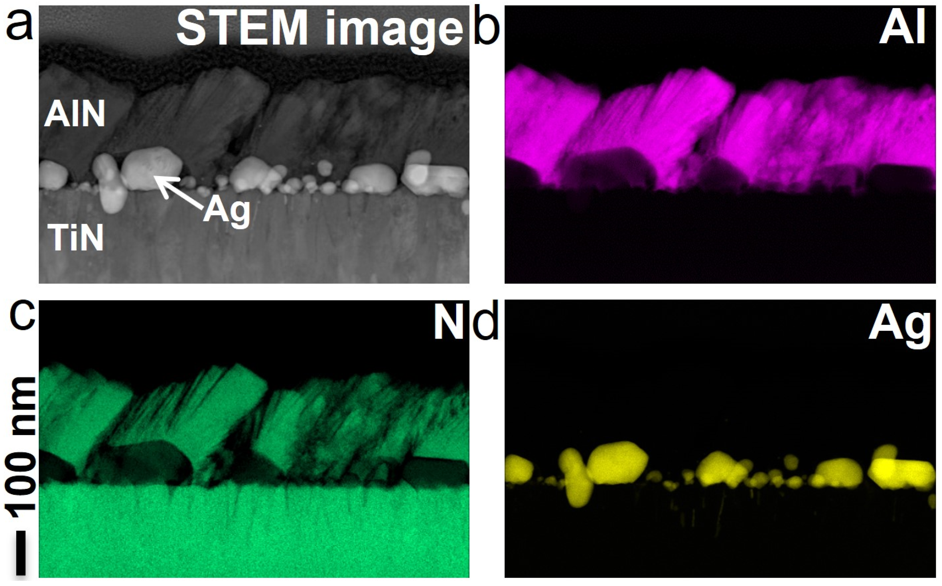
3.2. Dependence on Nanoparticle Material

The choice of seed material used in the growth of AlN nanostructures can significantly impact the temperature requirements of the process and growth conditions because of the melting point, reactivity, etc. Above, the formation of AlN nanostructures on Ag nanoparticles is discussed. To explore how various seed materials influence the growth of these nanostructures, two additional metals, Al and Au, are investigated. Figure 7 shows the cross-sectional SEM images of nanostructured AlN films grown under GLAD for 1 h using different seed materials (Al, Ag, and Au) but keeping the other deposition parameters the same, which yields deposition rates of 0.45, 0.5, and 0.26 nm/s, respectively.
The lateral dimensions and length of AlN nanostructures are found to be strongly affected by the type of metal used. Lateral dimensions of the nanostructures are found to be related to the sizes of seeded particles. This issue is discussed later in more detail for the case of Ag. Considering the length, the use of Ag leads to the growth of the longest structures, followed by Al and then Au, with approximately half of the length compared to the case of Ag particles. Thus, one assume that the nanoparticles not only serve as the nucleation spots for AlN, but also there is a catalytic enhancement of the AlN growth. It is well-known that catalyst particles can stimulate the formation of 1D nanostructures, like semiconductor nanowires or whiskers [36,37]. In this sense, Au has been among the most studied catalytic materials. For instance, it was shown that using Au and varying the nitridation of Al powders allowed the formation of AlN structures of various shapes, like nano-flowers, -cones, or -wires, depending on the substrate temperature during deposition [38]. It is important to stress that, contrary to the cases of vapor–liquid–solid or chemical vapor deposition methods, where the formation of the nanowires or nanorods is catalyzed by nanoparticles that appear to remain at the top of the nanorods during growth [5,12,39], for the reactive magnetron sputtering, the nanoparticles serve as a base defining a different growth mechanism. In this context, however, it is not clear why Ag nanoparticles provid the best growth rate for our nanostructures. This issue requires further investigation.
As mentioned above, the size of catalyst particles is an important factor varying the parameters of resulting nanostructures [40]. This effect can be seen in Figure 8, representing cross-sectional images of AlN nanostructures grown on the Ag nanoparticles obtained from films with nominal deposited metal thicknesses of 30, 50, and 70 nm. Increasing the thickness leeds to the formation of nanoparticles with larger lateral sizes. The larger nanoparticles facilitat the growth of nanostructures with larger lateral dimensions. Hence, varying the amount of deposited metal and, thus, the seed particle size enables the control of dimensions of the nanostructures.

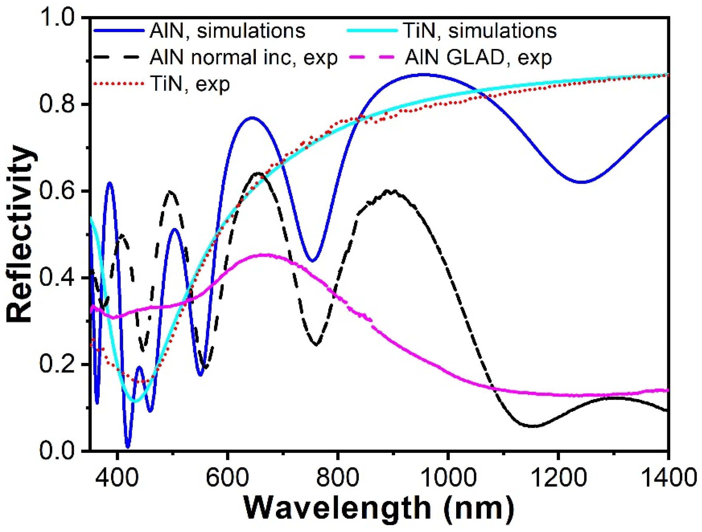
3.3. Linear Optical Characterization

Optical techniques probe average properties over large areas, which may be difficult to evaluate from TEM measurements. Figure 9 compares the reflectivity spectra from a nominal 430 nm thick nanostructured AlN film grown at normal incidence under GLAD on a substrate with Ag nanoparticles. Reflectivity from a 250 nm TiN film is also presented. The TiN layer is strongly absorbing with metallic characteristics. Thus, with 250 nm TiN, the light would not reach the TiN/Si interface, except for the UV part below wavelength of 350 nm, where a small effect of the TiN thickness is seen in the simulations. As such, the TiN layer essentially functions as the substrate, and the optical properties of the TiN layer are important for the reflectivity spectra of the nanostructured AlN top layer.
The dielectric constant of the TiN film is described by a Drude–Lorentz model, with the Drude term describing the metallic properties and two Lorentz oscillator terms representing interband resonances in the background ionic system. The optical properties of TiN films at different temperatures investigated by Reddy et al. [41] and Krekeler et al. [31] agree very well and are used in the present work. For the AlN film, the refractive index is modeled according to the work of Antoine-Vincent et al. [42]. Results of the simulated reflections for the normal incidence grown AlN/TiN/Si system are shown in Figure 9. It is seen that the decrease in reflectivity for wavelengths below 500 nm is well described by the chosen optical properties for TiN. However, the low reflectivity toward the infrared end of the spectrum is not explained by the properties of TiN and AlN. It is suggested that a broad plasmon resonance band extending into the near-infrared region generated by the Ag particles in the high-refractive index AlN film causes the low reflectivity in the spectral interval from 900 to 1400 nm.
The period of the interference oscillations in the reflectivity from the stack is determined by the thickness of the AlN film, while the contrast is influenced by the reflection coefficients at the two interfaces of the AlN film. As can be seen in Figure 9, this period observed in the experiments is in a good correlation with the simulations in the spectral range from 500 to 900 nm for a thickness of 430 nm and the chosen optical properties of the layers.
The linear reflectivity spectra of AlN nanostructured films being grown at the same conditions but with normal and 85° glancing angles, respectively, differ significantly (see Figure 9). While the sample grown at normal incidence shows well-defined interference oscillations, the GLAD sample provides a weak contrast in the spectral oscillations with a much longer period than for the normal incidence sample. Given that the nanocolumns grow at an angle of 33° relative to the surface normal and the deposition rate is much lower, the GLAD film is significantly thinner (by a factor of ca. 3.5) than the normal deposited one, while it has larger PTP surface variations as found using AFM. These factors explain the reduced contrast in spectral oscillations. The nanostructured film obtained under GLAD is also less dense (comparing Figure 2 and Figure 4), thus, leading to a decrease in the effective refractive index, causing an increase in the oscillation period.

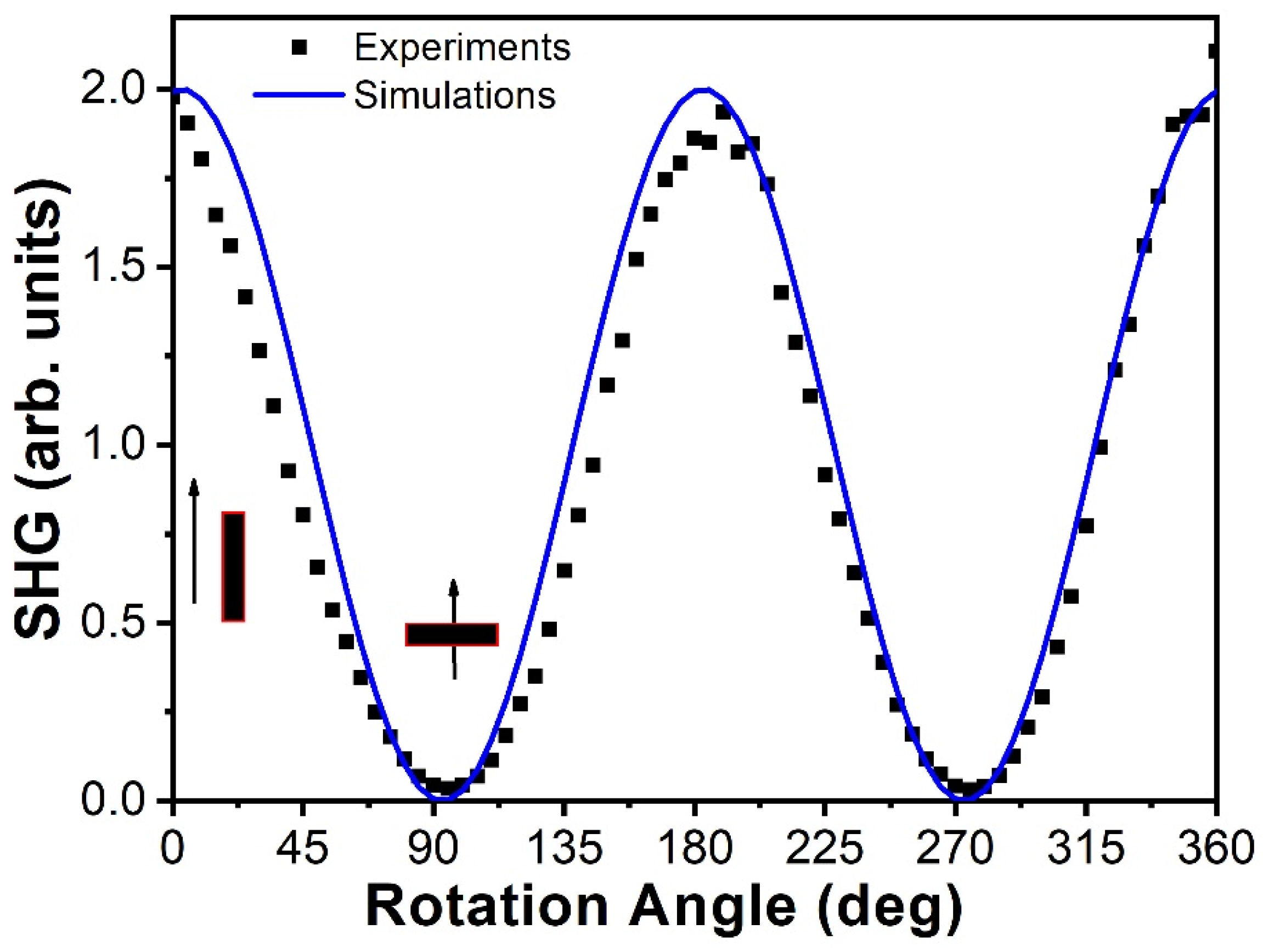
3.4. Second Harmonic Generation

The PZ effect and optical second harmonic generation (SHG) are described by third-rank response tensors with the same selection rules. SHG is highly sensitive to the crystal structure of the film and provides information about film crystallinity and properties. AlN is expected to grow following a wurtzite-like lattice with three independent nonlinear coefficients χ x z x , χ z x x , and χ z z z in the crystal coordinate system, where z is the direction along the c-axis [43]. In this coordinate system, either the pump field or the generated nonlinear field must have a component along the c-axis for SHG to occur. Typically, films deposited at normal incidence grow with the c-axis almost perpendicular to the surface. As shown above, this is also the case for our samples. Such films show strong SHG when the light is incident at an angle, but, as expected, they do not provide SHG when probed with light coming at normal incidence. Conversely, if the c-axis formed an angle with the surface normal, SHG would depend strongly on the azimuthal rotation of the sample around the surface normal.
The signal should disappear when the light is polarized perpendicularly to the AlN columns and maximize when the projection of the columns on the surface plane is along the direction of polarization. This is indeed what is seen in the rotational scan in Figure 10, where a good fit to the experimental data is obtained with a cosine squared dependence on rotational angle. This demonstrates that the AlN nanostructures formed by GLAD grow with the c-axis inclined relative to the surface normal. Furthermore, the high contrast in the rotational scan indicates that the c-axis of individual pillars is well oriented (does not have large deviations from pillar to pillar), although the angle of the c-axis can not be determined from these measurements. However, the data obtained through SHG combined with the SEM, HRTEM, and XRD results provide an overall clear picture of the structure of the grown samples.

4. Conclusions

AlN films with various thicknesses, ranging from a few tens to a few hundreds of nanometers, were grown using reactive magnetron sputtering on conductive TiN films deposited on silicon substrates. Al, Ag, and Au seed particles were used to break the film continuity and convert it into a nanostructured one. This scenario worked for both normal and glancing angle depositions. Using SEM and HRTEM, the AlN nanostructures were observed to nucleate and grow predominantly on the metal nanoparticles. They consisted of individual pillars/lamellae. It was found that varying the nanoparticle size and type of metal allowed tuning of the lateral dimensions of the nanostructures. Changing the deposition time provided a tool for controlling the nanostructure height/length. Thus, both dimensions could be efficiently engineered, providing nanostructures with desired parameters, which is an important factor for tuning the piezoelectric properties. It was found that Ag particles were more efficient in enhancing the growth of AlN than Al and Au under the same deposition conditions. The physical or chemical reason for this higher growth rate still needs to be clarified. During GLAD, the presence of Ag particles enhanced shadowing effects and, thus, increased the tilt angle of the pillars relative to the surface normal to 33°.
Cross-sectional HRTEM and related FFT data showed (0001) and (10-10) planes that were parallel to facets on the Ag particles, enabling conclusions about preferential c-axis growth of lamellae constituting the nanostructures. This finding was further supported by XRD spectra that revealed AlN (0002) and (10–11) planes. Additionally, the SHG rotational scans demonstrated that the c-axis of the AlN nanocrystals followed the growth direction, hence forming an angle with the surface normal of the GLAD film. Compared to normal deposition, GLAD led to the formation of less dense nanostructured films, which inevitably increased the surface height variations. These differences in film parameters between the normal and glancing angle cases caused a significant change in optical properties. It is worth noting that optical characterization is a simple and efficient method that allows for the probing of average properties over large areas; thus, it is advantageous in industrial applications.
Thus, the presented experimental results using a range of techniques demonstrated how the structure of AlN films could be engineered in reactive magnetron sputtering utilizing metal seed particles and varying the deposition angle (normal or glancing). This enables the design of film characteristics, such as mechanical, (piezo)electrical, and optical ones, and, thus, the optimization of their performance for the formation of materials with required functionality.

Author Contributions

Conceptualization, M.C., V.N.P. and K.P.; methodology, M.C. and V.N.P.; formal analysis, M.C., V.N.P. and K.P.; investigation, M.C.; fabrication, D.W. and P.K.K.; TEM imaging, T.K. and M.R.; resources, K.P.; data curation, M.C.; writing—original draft preparation, M.C., V.N.P. and K.P.; writing—review and editing, M.C., V.N.P. and K.P.; visualization, M.C.; supervision, K.P.; project administration, K.P.; funding acquisition, K.P. All authors have read and agreed to the published version of the manuscript.

Funding

This research was funded by the Novo Nordisk Foundation under the grant Nanoscale Energy Generators (number NNF20OC0064735).

Data Availability Statement

The data supporting this study are available on request from the corresponding authors.

Conflicts of Interest

The authors declare no conflict of interest.

References

  1. Liu, H.; Zhong, J.; Lee, C.; Lee, S.-W.; Lin, L. A comprehensive review on piezoelectric energy harvesting technology: Materials, mechanisms, and applications. Appl. Phys. Rev. 2018, 5, 041306. [Google Scholar] [CrossRef]
  2. Chen, F.; Ji, X.; Lau, S.P. Recent progress in group III-nitride nanostructures: From materials to applications. Mater. Sci. Eng. R Rep. 2020, 142, 100578. [Google Scholar] [CrossRef]
  3. Wu, Z.; Cheng, T.; Wang, Z.L. Self-Powered Sensors and Systems Based on Nanogenerators. Sensors 2020, 20, 2925. [Google Scholar] [CrossRef] [PubMed]
  4. Fei, C.; Liu, X.; Zhu, B.; Li, D.; Yang, X.; Yang, Y.; Zhou, Q. AlN piezoelectric thin films for energy harvesting and acoustic devices. Nano Energy 2018, 51, 146–161. [Google Scholar] [CrossRef]
  5. Wang, Z.L.; Song, J. Piezoelectric Nanogenerators Based on Zinc Oxide Nanowire Arrays. Science 2006, 312, 242–246. [Google Scholar] [CrossRef] [PubMed]
  6. Jamond, N.; Chrétien, P.; Houzé, F.; Lu, L.; Largeau, L.; Maugain, O.; Travers, L.; Harmand, J.C.; Glas, F.; Lefeuvre, E.; et al. Piezo-generator integrating a vertical array of GaN nanowires. Nanotechnology 2016, 27, 325403. [Google Scholar] [CrossRef] [PubMed]
  7. Gogneau, N.; Jamond, N.; Chrétien, P.; Houzé, F.; Lefeuvre, E.; Tchernycheva, M. From single III-nitride nanowires to piezoelectric generators: New route for powering nomad electronics. Semicond. Sci. Technol. 2016, 31, 103002. [Google Scholar] [CrossRef]
  8. Wang, X.; Song, J.; Liu, J.; Wang, Z.L. Direct-Current Nanogenerator Driven by Ultrasonic Waves. Science 2007, 316, 102–105. [Google Scholar] [CrossRef]
  9. Minary-Jolandan, M.; Bernal, R.A.; Espinosa, H.D. Strong piezoelectricity in individual GaN nanowires. MRS Commun. 2011, 1, 45–48. [Google Scholar] [CrossRef]
  10. Popok, V.N.; Chirumamilla, M.; Krekeler, T.; Ritter, M.; Pedersen, K. Magnetron Sputter Grown AlN Nanostructures with Giant Piezoelectric Response toward Energy Generation. ACS Appl. Nano Mater. 2023, 6, 8849–8856. [Google Scholar] [CrossRef]
  11. Agrawal, R.; Espinosa, H.D. Giant Piezoelectric Size Effects in Zinc Oxide and Gallium Nitride Nanowires. A First Principles Investigation. Nano Lett. 2011, 11, 786–790. [Google Scholar] [CrossRef] [PubMed]
  12. Kenry; Yong, K.-T.; Yu, S.F. AlN nanowires: Synthesis, physical properties, and nanoelectronics applications. J. Mater. Sci. 2012, 47, 5341–5360. [Google Scholar] [CrossRef]
  13. Nersisyan, H.H.; Lee, J.H.; Kim, H.Y.; Ryu, S.; Yoo, B.U. Morphological diversity of AlN nano- and microstructures: Synthesis, growth orientations and theoretical modelling. Int. Mater. Rev. 2020, 65, 323–355. [Google Scholar] [CrossRef]
  14. Dong, J.; Chen, L.; Yang, Y.; Wang, X. Piezotronic effect in AlGaN/AlN/GaN heterojunction nanowires used as a flexible strain sensor. Beilstein J. Nanotechnol. 2020, 11, 1847–1853. [Google Scholar] [CrossRef] [PubMed]
  15. Yazdi, G.R.; Persson, P.O.Å.; Gogova, D.; Fornari, R.; Hultman, L.; Syväjärvi, M.; Yakimova, R. Aligned AlN nanowires by self-organized vapor–solid growth. Nanotechnology 2009, 20, 495304. [Google Scholar] [CrossRef] [PubMed]
  16. Jaloustre, L.; Le Denmat, S.; Auzelle, T.; Azadmand, M.; Geelhaar, L.; Dahlem, F.; Songmuang, R. Toward Quantitative Measurements of Piezoelectricity in III-N Semiconductor Nanowires. ACS Appl. Nano Mater. 2021, 4, 43–52. [Google Scholar] [CrossRef]
  17. Mwema, F.M.; Akinlabi, E.T.; Oladijo, O.P. A systematic review of magnetron sputtering of AlN thin films for extreme condition sensing. Mater. Today Proc. 2020, 26, 1546–1550. [Google Scholar] [CrossRef]
  18. Jiao, X.; Shi, Y.; Zhong, H.; Zhang, R.; Yang, J. AlN thin films deposited on different Si-based substrates through RF magnetron sputtering. J. Mater. Sci. Mater. Electron. 2015, 26, 801–808. [Google Scholar] [CrossRef]
  19. Peng, M.Z.; Guo, L.W.; Zhang, J.; Yu, N.S.; Zhu, X.L.; Yan, J.F.; Wang, Y.; Jia, H.Q.; Chen, H.; Zhou, J.M. Effect of growth temperature of initial AlN buffer on the structural and optical properties of Al-rich AlGaN. J. Cryst. Growth 2007, 307, 289–293. [Google Scholar] [CrossRef]
  20. Shin, I.-S.; Kim, J.; Lee, D.; Kim, D.; Park, Y.; Yoon, E. Epitaxial growth of single-crystalline AlN layer on Si(111) by DC magnetron sputtering at room temperature. Jpn. J. Appl. Phys. 2018, 57, 060306. [Google Scholar] [CrossRef]
  21. Pingen, K.; Neuhaus, S.; Wolff, N.; Kienle, L.; Žukauskaitė, A.; von Hauff, E.; Hinz, A.M. Influence of Si(111) substrate off-cut on AlN film crystallinity grown by magnetron sputter epitaxy. J. Appl. Phys. 2023, 134, 025304. [Google Scholar] [CrossRef]
  22. Riah, B.; Camus, J.; Ayad, A.; Rammal, M.; Zernadji, R.; Rouag, N.; Djouadi, M.A. Hetero-Epitaxial Growth of AlN Deposited by DC Magnetron Sputtering on Si(111) Using a AlN Buffer Layer. Coatings 2021, 11, 1063. [Google Scholar] [CrossRef]
  23. Depla, D.; Dedoncker, R.; Strijckmans, K. Nitride formation during reactive sputter deposition of multi-principal element alloys in argon/nitrogen mixtures. Thin Solid Film. 2021, 732, 138721. [Google Scholar] [CrossRef]
  24. Iriarte, G.F.; Rodríguez, J.G.; Calle, F. Synthesis of c-axis oriented AlN thin films on different substrates: A review. Mater. Res. Bull. 2010, 45, 1039–1045. [Google Scholar] [CrossRef]
  25. Sandager, M.K.; Kjelde, C.; Popok, V. Growth of Thin AlN Films on Si Wafers by Reactive Magnetron Sputtering: Role of Processing Pressure, Magnetron Power and Nitrogen/Argon Gas Flow Ratio. Crystals 2022, 12, 1379. [Google Scholar] [CrossRef]
  26. Reusch, M.; Holc, K.; Pletschen, W.; Kirste, L.; Žukauskaitė, A.; Yoshikawa, T.; Iankov, D.; Ambacher, O.; Lebedev, V. Analysis and optimization of sputter deposited AlN-layers for flexural plate wave devices. J. Vac. Sci. Technol. B 2016, 34, 052001. [Google Scholar] [CrossRef]
  27. Iqbal, A.; Mohd-Yasin, F. Reactive Sputtering of Aluminum Nitride (002) Thin Films for Piezoelectric Applications: A Review. Sensors 2018, 18, 1797. [Google Scholar] [CrossRef]
  28. Marauska, S.; Dankwort, T.; Quenzer, H.J.; Wagner, B. Sputtered thin film piezoelectric aluminium nitride as a functional MEMS material and CMOS compatible process integration. Procedia Eng. 2011, 25, 1341–1344. [Google Scholar] [CrossRef]
  29. Barranco, A.; Borras, A.; Gonzalez-Elipe, A.R.; Palmero, A. Perspectives on oblique angle deposition of thin films: From fundamentals to devices. Prog. Mater. Sci. 2016, 76, 59–153. [Google Scholar] [CrossRef]
  30. Bairagi, S.; Järrendahl, K.; Eriksson, F.; Hultman, L.; Birch, J.; Hsiao, C.-L. Glancing Angle Deposition and Growth Mechanism of Inclined AlN Nanostructures Using Reactive Magnetron Sputtering. Coatings 2020, 10, 768. [Google Scholar] [CrossRef]
  31. Krekeler, T.; Rout, S.S.; Krishnamurthy, G.V.; Störmer, M.; Arya, M.; Ganguly, A.; Sutherland, D.S.; Bozhevolnyi, S.I.; Ritter, M.; Pedersen, K.; et al. Unprecedented Thermal Stability of Plasmonic Titanium Nitride Films up to 1400 °C. Adv. Opt. Mater. 2021, 9, 2100323. [Google Scholar] [CrossRef]
  32. Di Pietrantonio, F.; Fosca, M.; Benetti, M.; Cannatà, D.; Verona, C.; Teghil, R.; De Bonis, A.; Rau, J.V. Flower-like aluminium nitride nanostructures deposited by rf magnetron sputtering on superhard rhodium boride films. Appl. Phys. A 2019, 125, 681. [Google Scholar] [CrossRef]
  33. Ji, X.; Li, H.; Wu, Z.; Cheng, S.; Hu, H.; Yan, D.; Zhuo, R.; Wang, J.; Yan, P. Growth of AlN hexagonal oriented complex nanostructures induced by nucleus arrangement. CrystEngComm 2011, 13, 5198–5203. [Google Scholar] [CrossRef]
  34. Azadmand, M.; Auzelle, T.; Lähnemann, J.; Gao, G.; Nicolai, L.; Ramsteiner, M.; Trampert, A.; Sanguinetti, S.; Brandt, O.; Geelhaar, L. Self-Assembly of Well-Separated AlN Nanowires Directly on Sputtered Metallic TiN Films. Phys. Status Solidi (RRL) Rapid Res. Lett. 2020, 14, 1900615. [Google Scholar] [CrossRef]
  35. Chen, L.-C.; Tien, C.-H.; Chien, S.-Y.; Liao, W.-C.; Huang, C.-C.; Mu, C.-S.; Chen, C.-C.; Hsu, Y.-Y. A nanorods AlN layer prepared by sputtering at oblique-angle and application as a buffer layer in a GaN-based light emitting diodes. Proc. SPIE 2010, 7784, 778417. [Google Scholar]
  36. Wu, Y.; Yang, P. Direct Observation of Vapor−Liquid−Solid Nanowire Growth. J. Am. Chem. Soc. 2001, 123, 3165–3166. [Google Scholar] [CrossRef]
  37. Trentler, T.J.; Hickman, K.M.; Goel, S.C.; Viano, A.M.; Gibbons, P.C.; Buhro, W.E. Solution-Liquid-Solid Growth of Crystalline III-V Semiconductors: An Analogy to Vapor-Liquid-Solid Growth. Science 1995, 270, 1791–1794. [Google Scholar] [CrossRef]
  38. Yu, L.; Hu, Z.; Ma, Y.; Huo, K.; Chen, Y.; Sang, H.; Lin, W.; Lu, Y. Evolution of aluminum nitride nanostructures from nanoflower to thin film on silicon substrate by direct nitridation of aluminum precursor. Diam. Relat. Mater. 2007, 16, 1636–1642. [Google Scholar] [CrossRef]
  39. Jiang, R.; Meng, X. Synthesis of aluminum nitride nanostructures via chemical vapor deposition method with nickel as catalyst. Rev. Mex. Física 2018, 64, 67–71. [Google Scholar] [CrossRef]
  40. Yu, L.; Lv, Y.; Zhang, X.; Zhang, Y.; Zou, R.; Zhang, F. Vapor–liquid–solid growth route to AlN nanowires on Au-coated Si substrate by direct nitridation of Al powder. J. Cryst. Growth 2011, 334, 57–61. [Google Scholar] [CrossRef]
  41. Reddy, H.; Guler, U.; Kudyshev, Z.; Kildishev, A.V.; Shalaev, V.M.; Boltasseva, A. Temperature-Dependent Optical Properties of Plasmonic Titanium Nitride Thin Films. ACS Photonics 2017, 4, 1413–1420. [Google Scholar] [CrossRef]
  42. Antoine-Vincent, N.; Natali, F.; Mihailovic, M.; Vasson, A.; Leymarie, J.; Disseix, P.; Byrne, D.; Semond, F.; Massies, J. Determination of the refractive indices of AlN, GaN, and AlxGa1−xN grown on (111)Si substrates. J. Appl. Phys. 2003, 93, 5222–5226. [Google Scholar] [CrossRef]
  43. Blanc, D.; Cachard, A.; Pommier, J. All-optical probing of material structure by second harmonic generation: Application to piezoelectric aluminium nitride thin films. Opt. Eng. 1997, 36, 1191–1195. [Google Scholar] [CrossRef]
Figure 1. Cross-sectional SEM images of AlN grown at (a,c) normal and (b,d) glancing angle deposition for the cases (a,b) without and (c,d) with Ag nanoparticles.
Applnano 04 00016 g001
Figure 2. (a) Cross-sectional STEM image and (bd) corresponding chemical composition, obtained using EDS, of AlN nanostructures on Ag nanoparticles grown by GLAD. Nanoparticles are visible as light grey structures at the TiN and AlN interface in panel (a).
Applnano 04 00016 g002
Figure 3. (a,b) Cross-sectional HRTEM images of AlN nanostructures grown by GLAD and (c) magnified view of AlN at the interfaces with the nanoparticles. (d) FFTs of the selected areas (i), (ii), and (iii) depicted in (c). Red circles indicate reflections of certain planes. See text for details about identified planes and directions.
Applnano 04 00016 g003
Figure 4. (a) Cross-sectional STEM image and (bd) associated chemical composition, as revealed using EDS, of AlN nanostructures formed under normal deposition on Ag nanoparticles.
Applnano 04 00016 g004
Figure 5. XRD spectra of nanostructured AlN films grown under normal deposition and GLAD configuration.
Applnano 04 00016 g005
Figure 6. AFM images of nanostructured films grown for 83 and 50 min on Ag nanoparticles at (a) normal and (b) glancing angles, respectively.
Applnano 04 00016 g006
Figure 7. Cross-sectional SEM images of the AlN films under glancing angle growth on (a) Al, (b) Ag, and (c) Au nanoparticles for 1 h. Insets show the corresponding seed particles on TiN surface prior to AlN growth.
Applnano 04 00016 g007
Figure 8. Cross-sectional SEM images of AlN nanostructures grown on the Ag nanoparticles obtained from film with nominal thickness of (a) 30, (b) 50, and (c) 70 nm. Corresponding increase in lateral sizes of individual nanostructures is observed.
Applnano 04 00016 g008
Figure 9. Optical reflectance of the AlN film grown at normal incidence deposition with Ag particles shown along with the reflectance of a TiN film on Si, which was used as substrate for the AlN film. The experimental results are shown together with results of simulations on TiN and an ideal AlN film.
Applnano 04 00016 g009
Figure 10. Variation of SHG (experimental and simulated) with the rotational angle around the surface normal recorded with normal incidence light on a GLAD sample grown on Ag nanoparticles. The pump wavelength was 900 nm. Zero rotational angle corresponds to light polarization along the nanocolumns.
Applnano 04 00016 g010
Disclaimer/Publisher’s Note: The statements, opinions and data contained in all publications are solely those of the individual author(s) and contributor(s) and not of MDPI and/or the editor(s). MDPI and/or the editor(s) disclaim responsibility for any injury to people or property resulting from any ideas, methods, instructions or products referred to in the content.

