Abstract
TiO2 composites with polypyrrole have gained attention for various applications; however, some reported results on the suitability of this heterojunction for photoelectrochemical water oxidation do not agree. In this sense, it is relevant to further study this material to clarify the role of polypyrrole in this system. Here, TiO2 nanorods were grown on fluorine-doped tin oxide (FTO) substrates by a hydrothermal route; then, polypyrrole coatings were electrochemically synthetized on TiO2 nanorods using a galvanostatic signal. The heterojunctions were characterized by different spectroscopic, microscopic, and electrochemical techniques. As a result, it was found that the polypyrrole underwent a rapid degradation process and that this process occurred independently of the amount of polymer deposited on the TiO2, the illumination direction (back and front of the photoanode), and the type of light used (UV-Vis and Vis). In addition, from the measurements of the band positions of TiO2 and the HOMO level of polypyrrole, it was shown that the TiO2–polypyrrole heterojunction is not suitable for achieving the transfer of photogenerated holes to the electrolyte. These findings contribute to understanding the properties and interaction of two components of wide interest in materials science.
1. Introduction
TiO2 composites with polypyrrole (PPy) have been studied for different applications, including batteries [1,2], supercapacitors [3,4,5], adsorption of contaminants [6,7,8], and photocatalytic degradation of dyes [9,10,11]; however, the use of TiO2–PPy heterojunctions in photoelectrochemistry has not been studied in depth, and some reports do not seem to agree. With regard to TiO2, it is a widely used semiconductor for photoelectrochemical applications due to its availability, high stability, and low cost [12,13], but its low light absorption (related to its large bandgap, 3.2 eV) and its low charge separation and mobility hinder the performance of TiO2 in photoelectrochemistry [14]. In the case of PPy, it is a conducting polymer with thermal and environmental stability, good electric conductivity, light absorption capability, and interesting redox properties [15,16]; furthermore, the activity of pure PPy for photocatalysis has been demonstrated, especially for the oxidation of dye molecules [17,18,19].
Since photoelectrochemistry is considered a potential route for the sustainable production of hydrogen, there is interest in improving the performance of the photoelectrodes used in this technology. Ideally, a photoelectrode should be photoactive (to convert photons to long-lived charge carriers), catalytic (to facilitate the reaction with minimal energy loss), and stable (to ensure consistent performance over time). However, to date, no single material or composite has been identified that simultaneously possesses all these properties, so photoelectrochemical H2 production has not yet been implemented [20,21]. In particular, the development of efficient photoanodes to carry out the oxygen evolution reaction (OER) represents a challenge due to the four-electron transfer involved in the process [22,23]. Consequently, strategies such as doping [24,25], morphology changes [26], surface modifications [27,28], formation of heterojunctions [29,30], or a combination of these are commonly applied to increase the efficiencies of photoanodes. In this work, we have focused on the study of TiO2 heterojunctions with polypyrrole due to the reported evidence on these materials in photoelectrochemistry.
Luo, J. et al. synthetized TiO2 nanotubes coated with PPy. In that work, both TiO2 and PPy were obtained by electrochemical routes, and the composite material was tested as a photoanode using a KOH solution as the electrolyte. They reported a maximum photocurrent with TiO2–PPy of 3.48 mA/cm2, which was 2.4 times higher than that of TiO2. Strikingly, it was reported that the heterojunction presented greater stability than TiO2 itself, which was attributed to photocorrosion resistance of PPy. Regarding the increase in current, it was mentioned that PPy acted as a sensitizer, improving light absorption [31].
Li, X. et al. prepared a composite material (TiO2–Pd–PPy) obtained by the photoreduction of palladium ions and the photooxidation of pyrrole directly on TiO2. Subsequently, that material was deposited on FTO substrates to carry out a photoelectrochemical characterization using a solution of Na2SO4 with methanol as the electrolyte. In that study, the composite material allowed the achievement of a photocurrent 6.3 and 11.8 times higher than those of pure TiO2 when UV-Visible and visible light irradiation were used, respectively. Nevertheless, the authors mentioned that the composite material was unable to oxidize water due to the overvoltage of the reaction, so the presence of methanol was necessary as a sacrificial agent [32].
Rasouli, H. et al. fabricated a photoanode of polypyrrole electrochemically deposited on a titanium substrate coated with mixed metal oxides (TiO2–RuO2); then, the electrode was characterized for photoelectrochemical water splitting in a Na2SO4 solution. The authors reported that the composite material led to a photocurrent of 4.31 mA/cm2 (at 1.23 V vs. RHE), which was four times higher than that of pure PPy [33]. In that study the obtained photocurrents (measured by linear sweep voltammetry) were attributed to the oxygen evolution reaction; however, the cyclic voltammetry characterizations suggest that the currents are probably partially attributed to the redox properties of the electrodes.
El-Bery, H. M. et al. synthetized TiO2 nanocomposites with PPy by an impregnation route where TiO2 powder was mixed with a PPy solution. The composite material was deposited on FTO substrates by wet chemical deposition and tested as photoanode in a photoelectrochemical system using a Na2SO4 solution as the electrolyte. As result, the maximum photocurrent obtained with TiO2–PPy was 354 µA/cm2, which was 12 times higher than that of pure TiO2. The authors attributed the improvement to both the inhibition of recombination of photogenerated carriers and the increased light collection by the electrode [34].
Recently, Pal, S. et al. prepared a TiO2 nanocomposite with PPy by dispersing TiO2 nanoparticles in a PPy nanofiber solution. Then, thin films of the nanocomposite were deposited on FTO substrates and tested as photoanodes in a photoelectrochemical cell using a Na2SO4 solution as the electrolyte. The authors reported that TiO2–PPy exhibited a photocurrent density of 43 µA/cm2 (at 0.9 V vs. Ag/AgCl), which was 10.7 times higher than that of pure PPy. However, it is important to highlight that in chronoamperometry measurements it was observed that after 300 s the photoelectrode current dropped to 1.5 µA/cm2, which suggests that the composite material was not stable [35].
The results presented above motivated us to delve deeper into the photoelectrochemical properties of the TiO2–PPy heterojunction, especially considering that in our previous work, we found that polypyrrole undergoes an over-oxidation process when subjected to anodic conditions [36]. In this way, the present research aims to contribute to clarifying the role of PPy in TiO2–PPy photoelectrodes used for photoelectrochemical water oxidation, which is valuable for providing guidance on the convenience of including PPy in the design of new photoanodes for water splitting. For this work, TiO2 nanorods were prepared on FTO substrates using a hydrothermal method, and then an electrochemical synthesis of PPy was carried out (varying the supplied electric charge) on the TiO2 electrodes. Finally, the composite material was subjected to physicochemical and electrochemical characterizations to study its properties and performance.
2. Materials and Methods
2.1. Materials
FTO substrates (Ossila, TEC 8, 25 mm × 12.5 mm, Sheffield, UK) were cleaned prior to use by consecutive ultrasonic baths in acetone, ethanol, and deionized water for 10 min each. HCl (37%, Merck, Darmstadt, Germany), titanium n-butoxide (97%, Merck), Na2SO4 (≥99.0%, Sigma-Aldrich, St. Louis, MI, USA), and LiClO4 (Sigma Aldrich, ≥95%, St. Louis, MI, USA) were used without further purification. Pyrrole (Sigma Aldrich, 98%, St. Louis, MI, USA) was distilled and stored under a nitrogen atmosphere, and acetonitrile (Sigma Aldrich, HPLC grade, St. Louis, MI, USA) was kept over molecular sieves.
2.2. Synthesis of TiO2 Nanorods
TiO2 nanorods were grown on FTO by a traditional hydrothermal method [37]. In a typical experiment, 15 mL of concentrated hydrochloric acid, 15 mL of deionized water, and 0.7 mL of titanium n-butoxide were mixed and stirred for 10 min. Then, a volume of 10 mL of this solution was transferred to a Teflon-lined stainless-steel autoclave, and a clean FTO substrate was located against the Teflon wall (face-down at an inclined angle ~60°). The autoclave was sealed and placed in an oven at a temperature of 150 °C for 5 hrs. After completion of the growth process, all samples were washed thoroughly with deionized water and annealed at 500 °C (in air) for 2 h. Finally, each sample was cut in half to obtain two electrodes.
2.3. Polymerization of Pyrrole on TiO2 Nanorods
The synthesis of PPy was carried out in an electrochemical cell with a quartz window. Here, FTO substrates coated with TiO2 were used as working electrodes, a platinum foil was used as a counter electrode, and an Ag/AgCl electrode (3 M NaCl, MF-2052, BASi, West Lafayette, IN, USA) was used as a reference electrode. For the polymerization, an electrochemical signal of 0.5 mA/cm2 was used, and the working electrode was illuminated from the FTO side with a light intensity of 100 mW/cm2. The amount of PPy deposited on TiO2 was controlled by adjusting the synthesis time to achieve specific electric charges: 5.2 s for 2.6 mC/cm2, 21.2 s for 10.6 mC/cm2, and 84.0 s for 42.0 mC/cm2. The synthesis solution was composed of pyrrole 0.25 M and LiClO4 0.5 M in acetonitrile +2% w/w H2O. The potentiostat/galvanostat used in all experiments was an Autolab PGSTAT302N (Metrohm, Herisau, Switzerland).
2.4. Characterizations
The morphologies of the TiO2 nanorods and PPy coatings were examined by scanning electron microscopy (SEM) using a Hitachi S-4800 (CIQTEK, Hefei, China), and photoelectrochemical characterizations were performed in Na2SO4 0.1 M. A 300 W xenon arc lamp was used for photoelectrodes irradiation (100 mW/cm2). Diffuse reflectance spectra were taken with an Analytik Jena SPECORD 50 PLUS spectrophotometer (Jena, Germany), and Raman spectra were taken with a HORIBA Scientific XploRA (Irvine, CA, USA) using a 532 nm laser. X-ray diffraction was performed on a Rigaku D/Max-2200PC (Tokyo, Japan) with Ultima III θ–θ goniometer, Cu Kα radiation (λ = 1.5406 Å, 40 kV, 40 mA). Patterns were collected from 20 to 80° (2θ) using a 0.02° step and 1.5 s counting time per step.
3. Results and Discussion
3.1. Elaboration of Photoelectrodes
TiO2 nanorods grown on FTO substrates were initially characterized by SEM (Figure S1), where an ordered morphology with perpendicular growth of the TiO2 nanorods to the substrate was observed. The nanorods were ~2 μm long, and the cross section (with approximately square geometry) presented edges of ~120 nm. In general, good size uniformity and few overlapped nanorods were found. Furthermore, no bare areas of FTO were identified, except those intentionally left for electrical connections. These types of coatings where nanostructured TiO2 is supported on a substrate are desirable to prevent the release of TiO2 nanoparticles into aquatic environments during or after use, which is important to prevent ecological disturbances and toxicity effects on various living beings [38,39]. Regarding the electrosynthesis of PPy on TiO2, the amount of the deposited polymer was controlled by adjusting the supplied electric charge (2.6, 10.5, and 42.0 mC/cm2). The presence of PPy on the electrodes was verified by Raman spectroscopy (Figure 1a) and easily visualized (Figure 1b) due of the intense visible light absorption of PPy.
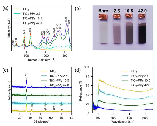
Figure 1.
Characterization of photoelectrodes. (a) RAMAN. (b) Photographs of bare TiO2 and TiO2 coated with PPy. (c) X-ray diffraction of TiO2 grown on FTO substrates. (d) Reflectance spectroscopy. The legends of 2.6, 10.5, and 42.0 represent the electric charge supplied during the polymerization of pyrrole on TiO2, in mC/cm2.
Based on electric charges stablished during the electrosynthesis of PPy, the amount of polymer deposited on TiO2 was estimated. The calculations were performed using Faraday’s law: m = Mq/zF, where m is the deposited mass (g/cm2), M is the molar mass of pyrrole (67.09 g/mol), q is the electric charge supplied (C/cm2), z is the number of electrons involved per monomeric unit, and F is the Faraday constant (96,500 C/mol) [40]. Accordingly, estimated polymer masses of 0.8, 3.2, and 13.0 µg/cm2 were obtained for electric charges of 2.6, 10.5, and 42.0 mC/cm2, respectively.
In the Raman spectra, bare TiO2 showed the typical characteristics of the rutile phase. Thus, bands were observed at 140 cm−1, 230 cm−1, 442 cm−1, and 605 cm−1, corresponding to the B1g, multiple scattering, Eg, and A1g modes, respectively [41,42,43]. The B1g mode is caused by symmetric bending vibration of O–Ti–O, the Eg mode is caused by the symmetric stretching vibration of O–Ti–O, and the A1g mode is caused by anti-symmetric bending vibration of O–Ti–O [44]. In the case of TiO2 coated with PPy, as the polymerization electric charge was increased, the signals from TiO2 became less intense, and those from PPy became more dominant. The band at 1568 cm−1 and the shoulder at 1600 cm−1 are attributed to a mixed C=C and C–C vibration of neutral and oxidized PPy, respectively. The bands at 1370 cm−1 and at 1330 cm−1 are ascribed to the ring stretching in PPy. The band at 1240 cm−1 is related to in-plane antisymmetric bending (C–H) vibrations. The band at 1045 cm−1 and the shoulder at 1072 cm−1 correspond to in-plane bending (C–H) vibrations, and the signals at 925 cm−1 and 967 cm−1 are associated with in-plane ring deformation for bipolarons and polarons, respectively [45,46]. Consequently, it can be stated that the coating observed macroscopically on the TiO2 (Figure 1b) is indeed the expected material (PPy). The TiO2 phase was verified by X-ray diffraction (Figure 1c), where (101), (111), (211), (002), and (112) planes associated with rutile were observed (JCPDS 21-1276) [24,30,47]. In the case of TiO2 coated with PPy, the diffraction patterns of TiO2 remained unchanged, indicating that the electrosynthesis of the polymer did not alter the crystalline structure of the inorganic semiconductor. Additionally, no signals attributed to polypyrrole were detected in the composite material, which is likely due to the low amount of polymer deposited.
The optical properties of the photoelectrodes were analyzed by reflectance spectroscopy (Figure 1d). Bare TiO2 exhibited the typical behavior of a semiconductor, where a sharp jump in the reflectance percentage appears as a consequence of the band gap energy (Eg) of the material. From a Tauc plot (Figure S2), the Eg of TiO2 was determined to be 3.04 eV, which is consistent with the expected value for TiO2 nanorods with the rutile crystalline phase [48,49,50,51]. On the other hand, the spectra of the TiO2 photoelectrodes coated with different amounts of PPy showed notable changes. As expected, due to the intense light absorption of PPy, the reflectance percentage of the composite material (in the range from 400 nm to 1100 nm) progressively decreased as the polymerization electric charge increased. In this way, when an electric charge of 42 mC/cm2 was supplied, the jump in the reflectance percentage practically disappeared. Now, although Tauc plots of inorganic semiconductors coated with other materials are found in the literature to show changes in Eg, it has been reported that this practice can lead to incorrect interpretations [52]. For this reason, Tauc plots of the TiO2–PPy system are not shown in this work.
The morphology and uniformity of the polypyrrole coatings on the TiO2 nanorods were examined by SEM images (Figure 2). These analyses demonstrated that following the electrosynthesis of PPy, the nanostructured morphology of TiO2 was preserved, with the nanorods remaining vertically aligned. However, the surface of the nanorods exhibited a roughness absent in the bare TiO2 (Figure S1). This roughness is characteristic of polypyrrole layers [53,54], indicating that the polymer was uniformly deposited onto the TiO2 surface and conformed to the morphology of the nanorods when the three polymerization electric charges (2.6, 10.5, and 42.0 mC/cm2) were supplied. Moreover, no localized accumulations of the polymer were detected, which is consistent with the macroscopically perceived homogeneity of the coatings.
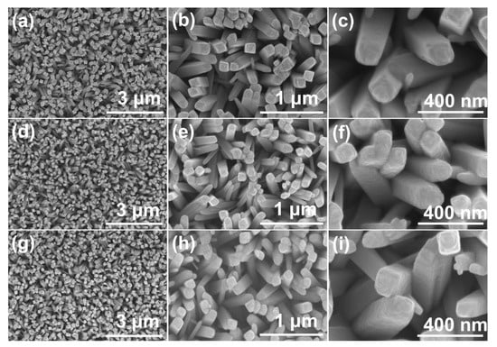
Figure 2.
SEM images of TiO2 nanotubes coated with electrochemically synthetized PPy. Electric charge supplied during polymerization: (a–c) 2.6 mC/cm2, (d–f) 10.5 mC/cm2, and (g–i) 42.0 mC/cm2.
3.2. Photoelectrochemical Characterization
The photoelectrochemical performance of TiO2 was initially measured by linear sweep voltammetry (LSV) (Figure 3a) using back side illumination (FTO side) and front side illumination (semiconductor/electrolyte side). Better performance of the photoelectrode was found using front illumination, which indicates that hole transport is more difficult than electron transport in the TiO2 synthesized in this work. When a photoanode is illuminated from the front, most of the light is absorbed near the semiconductor/electrolyte interface; this means that the photogenerated electrons have to travel a greater distance than the holes. In the case of backside illumination, the holes have to travel a greater distance compared with the electrons [55,56]. Regarding the characterizations under dark conditions (dashed lines), no appreciable currents were recorded in the entire potential range, which suggests that TiO2 did not experience degradation due to the applied potentials.
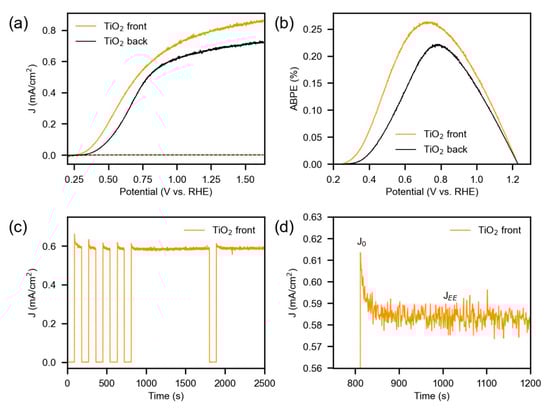
Figure 3.
Photoelectrochemical characterizations of bare TiO2. (a) Linear sweep voltammetry (LSV) under illumination (solid lines) and without illumination (dashed lines), scan rate of 10 mV/s. (b) ABPE plot obtained from the linear sweep voltammetry. (c) Chronoamperometry under chopped illumination, at 1.0 V vs. RHE. (d) Magnification of the current obtained when going from dark to illuminated conditions.
From the LSV curves, the applied bias photon-to-current efficiency (ABPE) was calculated using Equation (1). Here, Jph is the photocurrent density at the applied potential (mA/cm2), Vt is the theoretical potential for water electrolysis (1.23 V), Vb is the applied potential (V vs. RHE), and Pt is the incident power density of the light (100 mW/cm2). The maximum efficiency (0.26%) was achieved at a potential of 0.73 V vs. RHE with the front-illuminated TiO2 (Figure 3b). Under the same potential the efficiency of the back-illuminated TiO2 was 0.22%. These values are within the ranges of some reports in the literature for TiO2 [57,58,59,60].
With regard to the stability of the TiO2 nanorods, this was analyzed by a chronoamperometry measurement applying 1.0 V vs. RHE and using intermittent frontal illumination (Figure 3c). The characterization showed a high stability of the photocurrents and a rapid reaction of the TiO2 to changes from darkness to illumination and vice versa. When the illumination was activated, the photocurrents instantly increased to a peak value (J0) and then fell to a steady-state value (JEE) as part of the photogenerated electrons and holes underwent recombination (Figure 3d). Such recombination may be due to the accumulation of holes near the surface, to the accumulation of electrons throughout the coating (by slow transport), or to the trapping of electrons or holes in surface states [55]. Considering that the difference between J0 and JEE was approximately 0.03 mA/cm2 (5%), it can be inferred that at the applied potential, the TiO2 nanorods presented a relatively low recombination of the electron–hole pairs.
The photoelectrochemical performance of the TiO2–PPy composite was measured by LSV using front illumination and back illumination. Initially, photoelectrodes in which the polymer was synthesized with an electric charge of 10.5 mC/cm2 were evaluated (Figure 4a with back illumination and Figure 4b with front illumination). As a result, polypyrrole did not improve the photoelectrochemical response of TiO2 in any of the illumination directions; on the contrary, lower photocurrents were obtained with the presence of PPy than those obtained with bare TiO2. Furthermore, regardless of the illumination direction, the first LSV scan (denoted as TiO2-PPy-1) showed signs of oxidation processes, but the shape of the curve is an indication that these processes correspond to oxidation and overoxidation (degradation) of the polypyrrole. When a second LSV scan was performed (TiO2-PPy-2), both the shape of the curve and the magnitudes of the currents were closer to those observed for bare TiO2, indicating that during the first LSV scan most of the anodic current is attributed to oxidative degradation of the polymer.
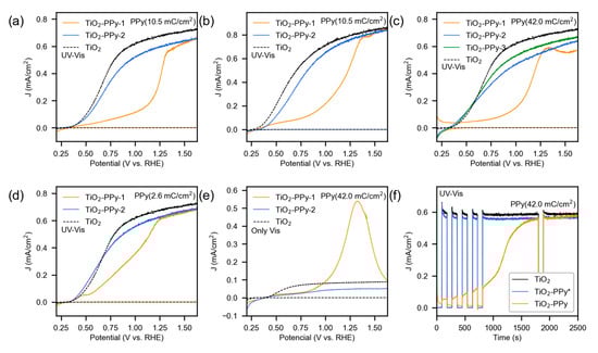
Figure 4.
Photoelectrochemical characterizations of TiO2–PPy. UV-Vis indicates that both ultraviolet and visible radiation were used. Only Vis indicates that only visible radiation was used. (a) Linear sweep voltammetry (LSV) with back illumination, PPy synthetized with 10.5 mC/cm2. (b) LSV with front illumination, PPy synthetized with 10.5 mC/cm2. (c) LSV with back illumination, PPy synthetized with 42.0 mC/cm2. (d) LSV with back illumination, PPy synthetized with 2.6 mC/cm2. (e) LSV with back illumination, PPy synthetized with 42.0 mC/cm2. (f) Chronoamperometry with front illumination at 1.0 V vs. RHE, PPy synthetized with 42.0 mC/cm2. In the LSV plots, the number “X” in the TiO2-PPy-X legends indicates the LSV scan number. In the chronoamperometry plot, TiO2-PPy indicates a fresh photoelectrode, while TiO2-PPy* indicates a photoelectrode after being exposed to an LSV scan.
Photoelectrodes in which the polymer was synthesized with electric charges of 2.6 mC/cm2 and 42.0 mC/cm2 were also evaluated by LSV. In the case of 42 mC/cm2 (Figure 4c), a similar trend as that found with 10.5 mC/cm2 was observed, that is, a first LSV scan (also denoted as TiO2-PPy-1 for consistency) that at low potentials shows small oxidation currents but that as the potential increases exhibits a drastic change in slope (~1.0 V vs. RHE). Such a change in slope may be associated with the onset of irreversible degradation of the polymer. In the second and third LSV scans (TiO2-PPy-2 and TiO2-PPy-3, respectively), similar curves were observed, although the third curve showed current densities slightly higher and closer to those obtained with pure TiO2. On the other hand, with the lowest synthesis electric charge (2.6 mC/cm2) it was more difficult to notice the start of the overoxidation process (Figure 4d). This may be due to the lower amount of polymer, which makes possible the photoelectrochemical oxidation of water on the exposed areas of TiO2.
Since the electric charge required for polymer degradation depends on the amount of polymer present, it is reasonable that the second LSV scan (TiO2-PPy-2) of the PPy synthesized with 2.6 mC/cm2 (Figure 4d) exhibited current values similar to those of bare TiO2. In contrast, for the PPy synthesized with 42.0 mC/cm2, the second LSV scan still showed current values somewhat different from those of TiO2 (Figure 4c). In relation to this, it has been reported that a fresh conductive PPy in the neutral state can be oxidized to a reversible state using approximately 10% of the electric charge supplied during polymerization. However, if this limit is exceeded, the polymer begins to undergo irreversible overoxidation [61]. In the case of bare TiO2, the electric charge associated with the photocurrent during an LSV scan was 156 mC/cm2 under front illumination and 129 mC/cm2 under back illumination. In this context, it is understandable that a single LSV scan was sufficient to overoxidize the synthesized polypyrrole with any of the three applied electric charges.
Furthermore, only visible light was used to irradiate the TiO2–PPy photoelectrodes in order to decrease the amount of light absorbed by TiO2 (due to its band gap) and promote electron–hole pairs to be preferentially generated in PPy. The result of the LSV characterization (Figure 4e) again showed that the polypyrrole undergoes degradation in the first potential scan (TiO2-PPy-1), but in this case, a well-defined oxidation peak was observed with a maximum at 1.32 V vs. RHE. The appearance of this peak can be attributed to the depletion of the polymer available for degradation since as the PPy was consumed, the current decreased to a base magnitude, which corresponded to that generated by TiO2. In the second LSV scan (TiO2-PPy-2), no defined oxidation peaks were identified (the curve showed a similar trend to that of bare TiO2), implying that the entire polymer was degraded in the first LSV scan.
In some reported studies, oxidative degradation of polypyrrole has been observed to occur as low as 1.2 V vs. RHE in conventional electrochemical systems [36,62]. In the present work, polypyrrole is deposited on TiO2, which upon illumination generates holes with high oxidizing power. Therefore, it is understandable that the polymer degradation process began even at potentials lower than 1.0 V vs. RHE. With regard to the mechanism of PPy overoxidation, the formation of pyrrolinones with short conjugation lengths and CO2 resulting from the oxidation of terminal units has been evidenced [63].
The degradation of polypyrrole was also followed by chopped chronoamperometry measurements. A comparison under intermittent illumination of a fresh photoelectrode (denoted as TiO2-PPy) and a photoelectrode after being exposed to an LSV scan under illumination (denoted as TiO2-PPy*) is shown in Figure 4f. It is clear that after the LSV, the photoresponse of TiO2–PPy is close to that of bare TiO2. However, in the case of the fresh photoanode the photocurrent showed a gradual growth during the first 1800 s (while polypyrrole was consumed). In this case, the degradation occurs at a slower rate because at the potential applied in chronoamperometry (1.0 V vs. RHE), the intensity of oxidation is not as high as that observed above 1.2 V vs. RHE (Figure 4a).
Regarding the macroscopic appearance of TiO2–PPy, the fresh material presented an intense black color (Figure S3a), but since the first LSV scan was carried out, the color changed to a more grayish and opaque black. From the complete sequence of photographs (Figure S3b–f), it can be seen that the application of consecutive LSV scans on the TiO2–PPy led to a decrease in the polymeric coating. However, no detachment of the polypyrrole was observed during the measurements. This effect can be associated with the electrochemical degradation suffered by the PPy, which not only leads to the loss of the polymer’s electrical properties but also results in a progressive consumption of the material. As for the appearance of the composite material at microscopic scale (Figure 5), it was observed that after performing the first LSV scan, the TiO2 nanostructures did not change, which is consistent with the good stability of this inorganic semiconductor. In a different way, the polypyrrole coating exhibited a slightly more granular morphology (Figure 5b,d), which may be a consequence of the consumption of the material, affecting the amount of polymer present on the TiO2.
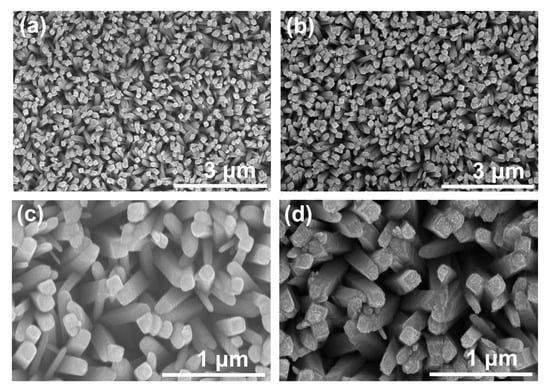
Figure 5.
SEM images of TiO2–PPy. (a,c) Fresh photoelectrode. (b,d) Photoelectrode after being subjected to one LSV scan. Electric charge supplied during polymerization of 42 mC/cm2.
In order to gain a deeper understanding of what happens to PPy in the composite, Raman spectroscopy characterizations were performed. Here, measurements were made on TiO2–PPy photoelectrodes after subjecting them to one LSV scan using front illumination and back illumination (Figure 6). In both cases, it was found that most of the polypyrrole signals remained after performing the photoelectrochemical test, but it was also observed that the signals associated with TiO2 became more intense. If the spectra are superimposed and the ratio of the highest intensity signal in PPy (1568 cm−1) to the highest intensity signal in TiO2 (610 cm−1) is calculated, it can be seen that after performing one LSV scan the ratio is 1.6 (with back illumination) and 1.8 (with front illumination). Since this ratio in the fresh photoelectrode is 3.5, it is clear that the photoelectrochemical process led to a decrease in the amount of polymer in the composite.
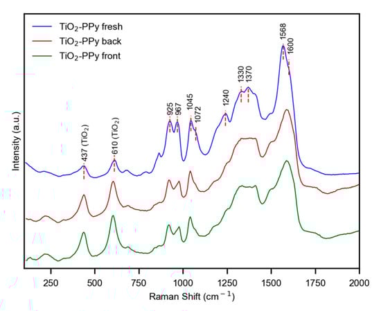
Figure 6.
Raman spectra of TiO2–PPy. Electric charge supplied during polymerization of 42 mC/cm2. Excitation wavelength of 532 nm.
On the other hand, it is known that a typical characteristic of overoxidized (degraded) polypyrrole is the decrease in the signal associated with the C–H bond (1240 cm−1); this as a result of the change that the polymer experiences due to the hydroxylation of the pyrrole rings in the β position [64,65]. It is worth mentioning that through an additional oxidation process, a hydroxylated product generates a carbonyl substituted structure, which in the case of PPy presents a characteristic Raman signal at ~1730 cm−1 [66]. In the present work, no signals were detected around 1730 cm−1, so it can be thought that the amount of C=O bonds present in the degraded PPy was not high enough to be detected by the Raman spectroscopy technique.
The energy bands of the two materials used in this work were analyzed by Mott–Schottky for TiO2 and HOMO level measurements for polypyrrole. In the case of Mott–Schottky characterization (Figure 7a), the resulting plot allows one to obtain the flat band potential (Vfb) of the semiconductor when the straight line that covers the linear part of the data intercepts the potential axis (1/C2 = 0). Since the flat band potential is closely related to the Fermi level [67], it is common to assume this value as the potential corresponding to the minimum level of the conduction band in n-type semiconductors or as the maximum level of the valence band in p-type semiconductors [50,68]. In some cases, to take into account the separation of these levels, the authors assume a difference of 0.1 or 0.2 eV [49,69]. Here, the Vfb of bare TiO2 was found to be 0.12 V vs. RHE or whichever is the same, −4.21 eV vs. vacuum or −0.29 V vs. NHE. Considering that the band gap of TiO2 was determined as 3.04 eV (Figure S2) and assuming a separation of 0.2 eV between the conduction band edge and the Fermi level, the conduction band minimum is located at −4.01 eV vs. vacuum (−0.49 V vs. NHE), while the valence band maximum is located at −7.05 eV vs. vacuum (2.55 V vs. NHE).
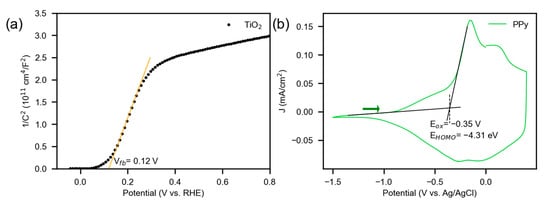
Figure 7.
(a) Mott–Schottky plot of TiO2 with 10 mV amplitude modulation at 1 kHz frequency in the dark, 0.1 M Na2SO4 as the electrolyte. (b) Cyclic voltammogram of polypyrrole synthesized on FTO, 0.1 M NBu4PF6 in acetonitrile as the electrolyte and 20 mV/s as the scan rate. The arrow indicates the sweep direction.
For the determination of the HOMO level of PPy, the polymer was synthesized directly on FTO, and a cyclic voltammogram (Figure 7b) was performed following previous reports [16,70,71]. Although it is expected that the polymer obtained on FTO will not have exactly the same properties as the one synthesized on TiO2, the determined HOMO level is useful to have an approximate diagram of the band positions of the materials when they are not in contact. Thus, the HOMO level of PPy was found to be −4.31 eV vs. vacuum (−0.19 V vs. NHE).
Using the data of the valence and conduction bands of TiO2 and the HOMO level of PPy, the band diagram of the materials was drawn in relation to the redox potentials of water splitting (Figure 8). The LUMO position of polypyrrole was located at −1.15 eV vs. vacuum (−3.35 V vs. NHE) since the band gap of pure PPy is 3.16 eV [72]. It is important to note that when polypyrrole is oxidized to a reversible level, polarons and bipolarons are formed, generating small electronic bands within the main band structure. These bands are responsible for the polymer’s conductivity and high light absorption [72]. Now, from the bands diagram it can be seen that PPy is not suitable for carrying out the oxidation of water, since its HOMO level is not negative enough (on the vacuum scale) for the reaction to take place.
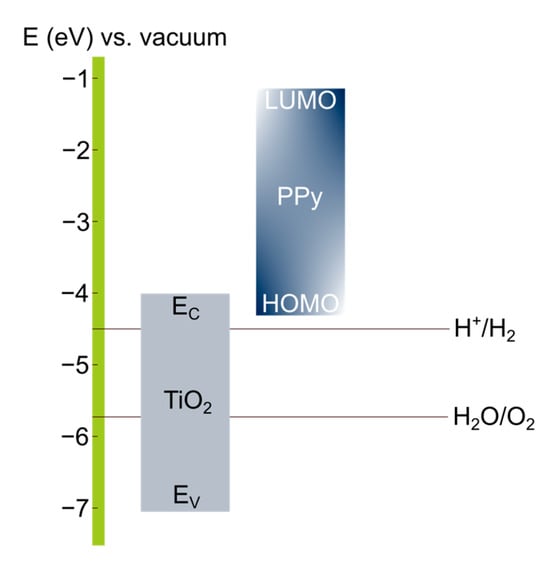
Figure 8.
Band position diagram of TiO2 and polypyrrole vs. vacuum.
Considering the nature of the materials, an n-type semiconductor in the case of TiO2 and a p-type semiconductor in the case of polypyrrole, the n–p heterojunction could be available to favor the separation of the charge carriers. Recent publications have shown that TiO2–PPy composites are valuable for achieving attractive electrical properties for the development of photocatalysts and electrochemical sensors [73,74,75]. For example, Milojković, N. et al. reported that a hybrid material of TiO2 with PPy enables the separation of photogenerated charge carriers due to the formation of a Z-scheme heterojunction. In that case, electrons in the conduction band of TiO2 combine with holes in the HOMO level of PPy, making the remaining holes in TiO2 available for oxidation reactions [73]. In the present work, this type of charge carrier separation is not convenient, due to the structure of the photoelectrode, since water oxidation is expected to occur on the PPy surface. Now, due to the impediment of polypyrrole to oxidize water, an accumulation of holes in the polymer can be expected, which subsequently degrade the material.
As a strategy, one could consider employing PPy as a catalyst support for water oxidation. However, it is important to note that hydroxyl radicals generated during water oxidation have been shown to be responsible for the overoxidation of PPy [62]. This means that in electrochemical systems incorporating polypyrrole for water splitting, it is essential to verify that the measured currents are not associated with the degradation of the polymeric material.
4. Conclusions
In this work, photoelectrodes composed of TiO2 nanorods coated with polypyrrole were synthesized and tested as photoanodes in a photoelectrochemical system. For this, TiO2 nanorods were grown on FTO substrates by a hydrothermal method, and then an electrochemical synthesis of polypyrrole on TiO2 was performed by a galvanostatic route. Characterizations by diffuse reflectance spectroscopy, SEM microscopy, and Raman spectroscopy allowed the demonstration of the successful production of the composite material. However, photoelectrochemical characterizations of TiO2–PPy for water oxidation showed a rapid degradation of the polymer. The results indicate that the degradation of polypyrrole in the photoelectrochemical process occurs independently of its thickness in the TiO2–PPy system. Furthermore, it can be suggested that the degradation of the polymer is not necessarily associated with the oxidizing power of the photoexcited holes in TiO2 but is more related to the difficulty of achieving the transfer of photogenerated holes from the TiO2–PPy heterojunction to the electrolyte. In light of the above, our results contribute to clarify the suitability of the presence of polypyrrole in the TiO2–PPy photoanode since some contradictions have been reported in the literature.
Supplementary Materials
The following supporting information can be downloaded at https://www.mdpi.com/article/10.3390/electrochem6030031/s1, Figure S1: SEM images of TiO2 nanorods grown on FTO substrates; Figure S2: Tauc plot of bare TiO2; Figure S3: Photographs of fresh TiO–PPy (A). Photographs of TiO2–PPy after being subjected to (B) 1 LSV scan, (C) 2 LSV scans, (D) 3 LSV scans, (E) 4 LSV scans, and (F) 5 LSV scans. Electric charge supplied during polymerization of 42 mC/cm2.
Author Contributions
Conceptualization, J.P., P.O. and M.T.C.; formal analysis, J.P., P.O. and M.T.C.; investigation, J.P.; methodology, J.P., P.O. and M.T.C.; supervision, P.O. and M.T.C.; writing—original draft, J.P.; writing—review and editing, J.P., P.O. and M.T.C. All authors have read and agreed to the published version of the manuscript.
Funding
The authors thank the Department of Chemistry and the Department of Chemical Engineering of the Universidad de los Andes (Colombia) for their support. M.T.C. thanks the Faculty of Science of the UA for the financial support (Project INV-2025-213-3345). Jhon Puerres acknowledges the support received from the CEIBA Foundation, the Department of Nariño (Colombia), and the Universidad de La Salle (Colombia). The authors acknowledge the instruments and scientific and technical assistance of the Microcore Microscopy Core at the Universidad de los Andes. The authors declare no competing interests.
Institutional Review Board Statement
Not applicable.
Informed Consent Statement
Not applicable.
Data Availability Statement
Data is contained within the article and the Supplementary Materials.
Acknowledgments
Jhon Puerres acknowledges the support received from the project “fortalecimiento de capacidades regionales en investigación, desarrollo tecnológico e innovación en el Departamento de Nariño”.
Conflicts of Interest
The authors declare no conflicts of interest.
Abbreviations
The following abbreviations are used in this manuscript:
| FTO | Fluorine-doped tin oxide |
| HOMO | Highest occupied molecular orbital |
| PPy | Polypyrrole |
| OER | Oxygen evolution reaction |
| SEM | Scanning electron microscopy |
| Eg | Band gap energy |
| LSV | Linear sweep voltammetry |
| ABPE | Applied bias photon-to-current efficiency |
| Vfb | Flat band potential |
| LUMO | Lowest unoccupied molecular orbital |
References
- Kang, C.; Song, K.; Ha, S.; Sung, Y.; Kim, Y.; Shin, K.-Y.; Kim, B.H. Influence of Polypyrrole on Phosphorus- and TiO2-Based Anode Nanomaterials for Li-Ion Batteries. Nanomaterials 2024, 14, 1138. [Google Scholar] [CrossRef] [PubMed]
- Liu, Y.; Wei, J.; Qiao, X.; Li, X.; Zhang, H.; Xiong, H. Enhanced Adsorption and Conversion of Polysulfides by ZIF-67-Based Co3O4/TiO2 Heterostructure and Attached Polypyrrole 3D Conductive Network for Lithium–Sulfur Batteries with Stable and Extended Cycling. Energy Technol. 2024, 12, 2301166. [Google Scholar] [CrossRef]
- Enailah, A.; Mohamed, F. Growth Mechanism of 2D Heterostructures of Polypyrrole Grown on TiO2 Nanoribbons for High-Performance Supercapacitors. Nanoscale Adv. 2024, 6, 5409–5419. [Google Scholar] [CrossRef]
- Cai, H.; Li, Y.; Liu, D.; Yang, X.; Zhou, D.; Han, E.; Li, X.; Li, Q.; He, Y. Construction of Moiré-like TiO2/Polypyrrole Electrodes for High Performance Photo-Assisted Supercapacitors. Colloids Surfaces A Physicochem. Eng. Asp. 2024, 703, 135386. [Google Scholar] [CrossRef]
- Azizi, E.; Arjomandi, J.; Shi, H.; Kiani, M.A. Flexible Polypyrrole/TiO2/MXene Nanocomposite Supercapacitor: A Promising Energy Storage Device. J. Energy Storage 2024, 75, 109665. [Google Scholar] [CrossRef]
- Barkade, S.S.; Nakate, U.T.; Bansod, P.G.; Deorukhkar, O.A.; Doss, V.R. Ultrasound-Assisted Synthesis of Polypyrrole/TiO2 Nanocomposite for Cu(II) Ions Removal from Aqueous Solution. Synth. Met. 2023, 293, 117253. [Google Scholar] [CrossRef]
- Chen, J.; Yu, M.; Wang, C.; Feng, J.; Yan, W. Insight into the Synergistic Effect on Selective Adsorption for Heavy Metal Ions by a Polypyrrole/TiO2 Composite. Langmuir 2018, 34, 10187–10196. [Google Scholar] [CrossRef]
- Omar, R.A.; Radwan, E.K.; Salih, S.A.; Mohamed, G.G. Synergistic Adsorption–Photocatalytic Degradation of the Emerging Contaminant Hydroxybenzotriazole by a 3D Sponge-like Easy Separation Polypyrrole/TiO2 Composite. Appl. Water Sci. 2024, 14, 229. [Google Scholar] [CrossRef]
- Nazir, M.K.; Javaid, S.; Afzal, H.; Taj, M.B.; Baamer, D.F.; Almasoudi, A.; Aldahiri, R.H.; Ali, O.M.; Khan, M.I.; Ahmed, M.M.; et al. Synthesis, Magnetic, and Photocatalytic Activity of Polypyrrole-Based TiO2–Fe Catalyst for Wastewater Treatment. Catalysts 2024, 14, 692. [Google Scholar] [CrossRef]
- Dhachanamoorthi, N.; Oviya, K.; Sugumaran, S.; Suresh, P.; Parthibavarman, M.; Jeshaa dharshini, K.; Aishwarya, M. Effective Move of Polypyrrole/TiO2 Hybrid Nanocomposites on Removal of Methylene Blue Dye by Photocatalytic Activity. Chem. Phys. Impact 2024, 9, 100723. [Google Scholar] [CrossRef]
- Zhang, J.; Pang, Z.; Sun, Q.; Chen, X.; Zhu, Y.; Li, M.; Wang, J.; Qiu, H.; Li, X.; Li, Y.; et al. TiO2 Nanotube Array Modified with Polypyrrole for Efficient Photoelectrocatalytic Decolorization of Methylene Blue. J. Alloys Compd. 2020, 820, 153128. [Google Scholar] [CrossRef]
- Balu, R.; Devendrapandi, G.; Gnanasekaran, L.; Karthika, P.C.; Abd-Elkader, O.H.; Kim, W.K.; Minnam Reddy, V.R.; Kapoor, M.; Singh, S.; Lavanya, M. Creating an Intermediate Energy Band to Boost the Photoelectrochemical Efficiency of TiO2 for Solar-Driven Hydrogen Production. Sol. Energy Mater. Sol. Cells 2025, 279, 113226. [Google Scholar] [CrossRef]
- Tu, J.; Li, J.; Pan, Z.; Zhu, X.; Ye, D.; Yang, Y.; Wang, H.; An, L.; Chen, R.; Liao, Q. Nitrogen-Doped CdS/TiO2 Nanorods Heterojunction Photoanode for Efficient and Stable Photoelectrochemical Water Splitting. J. Power Sources 2025, 628, 235883. [Google Scholar] [CrossRef]
- Li, A.; Liu, L.; Jiao, Z.; Han, M. Integration of Bi2S3 Nanoflowers into TiO2 Nanorods for Enhanced Photoelectrochemical Water Splitting Performance. Mater. Lett. 2025, 380, 137740. [Google Scholar] [CrossRef]
- Mazumdar, J.; Deb, S. Synthesis of Core-Shell Structured Silver-Polypyrrole Nanocomposite for Cost Effective Photocatalytic Degradation of Methylene Blue under Natural Sunlight. Mater. Lett. 2024, 358, 135755. [Google Scholar] [CrossRef]
- Puerres, J.; Ortiz, P.; Cortés, M.T. Effect of Electrosynthesis Potential on Nucleation, Growth, Adhesion, and Electronic Properties of Polypyrrole Thin Films on Fluorine-Doped Tin Oxide (FTO). Polymers 2021, 13, 2419. [Google Scholar] [CrossRef]
- Luhakhra, N.; Tiwari, S.K. Polaron and Bipolaron Mediated Photocatalytic Activity of Polypyrrole Nanoparticles under Visible Light. Colloids Surf. A Physicochem. Eng. Asp. 2023, 667, 131380. [Google Scholar] [CrossRef]
- Li, Y.; Yan, S.; Jia, X.; Wu, J.; Yang, J.; Zhao, C.; Wang, S.; Song, H.; Yang, X. Uncovering the Origin of Full-Spectrum Visible-Light-Responsive Polypyrrole Supramolecular Photocatalysts. Appl. Catal. B Environ. 2021, 287, 119926. [Google Scholar] [CrossRef]
- Yuan, X.; Floresyona, D.; Aubert, P.-H.; Bui, T.-T.; Remita, S.; Ghosh, S.; Brisset, F.; Goubard, F.; Remita, H. Photocatalytic Degradation of Organic Pollutant with Polypyrrole Nanostructures under UV and Visible Light. Appl. Catal. B Environ. 2019, 242, 284–292. [Google Scholar] [CrossRef]
- Schichtl, Z.G.; Carvalho, O.Q.; Tan, J.; Saund, S.S.; Ghoshal, D.; Wilder, L.M.; Gish, M.K.; Nielander, A.C.; Stevens, M.B.; Greenaway, A.L. Chemistry of Materials Underpinning Photoelectrochemical Solar Fuel Production. Chem. Rev. 2025, 125, 4768–4839. [Google Scholar] [CrossRef]
- Chen, P.; Kang, B.; Liu, P.; Cheng, X.; Zhong, S.; Wang, X.; Fang, B. Passivation Strategies for Enhanced Photoelectrochemical Water Splitting. J. Power Sources 2025, 628, 235860. [Google Scholar] [CrossRef]
- Abdullah, H.; Shuwanto, H.; Lie, J.; Sillanpää, M. Critical Parameters and Essential Strategies in Designing Photoanodes to Overcome the Sluggish Water Oxidation Reaction. J. Environ. Chem. Eng. 2023, 11, 109356. [Google Scholar] [CrossRef]
- Clarizia, L.; Nadagouda, M.N.; Dionysiou, D.D. Recent Advances and Challenges of Photoelectrochemical Cells for Hydrogen Production. Curr. Opin. Green Sustain. Chem. 2023, 41, 100825. [Google Scholar] [CrossRef]
- He, S.; Meng, Y.; Cao, Y.; Huang, S.; Yang, J.; Tong, S.; Wu, M. Hierarchical Ta-Doped TiO2 Nanorod Arrays with Improved Charge Separation for Photoelectrochemical Water Oxidation under FTO Side Illumination. Nanomaterials 2018, 8, 983. [Google Scholar] [CrossRef]
- Li, T.; Ding, D. Photoelectrochemical Water Splitting with Black Ni/Si-Doped TiO2 Nanostructures. Int. J. Hydrogen Energy 2020, 45, 20983–20992. [Google Scholar] [CrossRef]
- Cho, I.S.; Chen, Z.; Forman, A.J.; Kim, D.R.; Rao, P.M.; Jaramillo, T.F.; Zheng, X. Branched TiO2 Nanorods for Photoelectrochemical Hydrogen Production. Nano Lett. 2011, 11, 4978–4984. [Google Scholar] [CrossRef]
- Li, H.; Li, Z.; Yu, Y.; Ma, Y.; Yang, W.; Wang, F.; Yin, X.; Wang, X. Surface-Plasmon-Resonance-Enhanced Photoelectrochemical Water Splitting from Au-Nanoparticle-Decorated 3D TiO2 Nanorod Architectures. J. Phys. Chem. C 2017, 121, 12071–12079. [Google Scholar] [CrossRef]
- Zhou, S.; Liu, S.; Su, K.; Jia, K. Graphite Carbon Nitride Coupled S-Doped Hydrogenated TiO2 Nanotube Arrays with Improved Photoelectrochemical Performance. J. Electroanal. Chem. 2020, 862, 114008. [Google Scholar] [CrossRef]
- Yang, J.-S.; Lin, W.-H.; Lin, C.-Y.; Wang, B.-S.; Wu, J.-J. N-Fe2O3 to N+-TiO2 Heterojunction Photoanode for Photoelectrochemical Water Oxidation. ACS Appl. Mater. Interfaces 2015, 7, 13314–13321. [Google Scholar] [CrossRef] [PubMed]
- Liu, C.; Chen, L.; Su, X.; Chen, S.; Zhang, J.; Yang, H.; Pei, Y. Activating a TiO2/BiVO4 Film for Photoelectrochemical Water Splitting by Constructing a Heterojunction Interface with a Uniform Crystal Plane Orientation. ACS Appl. Mater. Interfaces 2022, 14, 2316–2325. [Google Scholar] [CrossRef] [PubMed]
- Luo, J.; Ma, Y.; Wang, H.; Chen, J. Preparation of Polypyrrole Sensitized TiO2 Nanotube Arrays Hybrids for Efficient Photoelectrochemical Water Splitting. Electrochim. Acta 2015, 167, 119–125. [Google Scholar] [CrossRef]
- Li, X.; Wang, P.; Huang, B.; Qin, X. Precisely Locate Pd-Polypyrrole on TiO2 for Enhanced Hydrogen Production. Int. J. Hydrogen Energy 2017, 42, 25195–25202. [Google Scholar] [CrossRef]
- Rasouli, H.; Hosseini, M.G.; Yardani sefidi, P.; Kinayyigit, S. Superior Overall Water Splitting Performance in Polypyrrole Photoelectrode by Coupling NrGO and Modifying Electropolymerization Substrate. J. Appl. Polym. Sci. 2021, 138, 50507. [Google Scholar] [CrossRef]
- El-Bery, H.M.; Salah, M.R.; Ahmed, S.M.; Soliman, S.A. Efficient Non-Metal Based Conducting Polymers for Photocatalytic Hydrogen Production: Comparative Study between Polyaniline, Polypyrrole and PEDOT. RSC Adv. 2021, 11, 13229–13244. [Google Scholar] [CrossRef]
- Pal, S.; Das, P.S.; Naskar, M.K.; Ghosh, S. Metal Oxide Nanocrystals Embedded Polypyrrole Nanohybrid: Exploring Role of Interface in Photocatalytic Hydrogen Generation. Mater. Today Sustain. 2024, 25, 100610. [Google Scholar] [CrossRef]
- Puerres, J.; Díaz, M.; Hurtado, J.; Ortiz, P.; Cortés, M.T. Photoelectrochemical Stability under Anodic and Cathodic Conditions of Meso-Tetra-(4-Sulfonatophenyl)-Porphyrinato Cobalt (II) Immobilized in Polypyrrole Thin Films. Polymers 2021, 13, 657. [Google Scholar] [CrossRef] [PubMed]
- Puerres, J.; Polanía, S.; Pérez-Torres, A.F.; Erazo, E.A.; Cortés, M.T.; Ortiz, P. Reduced TiO2 Nanorods Decorated with Carbon Nanodots for Photoelectrochemical Water Oxidation. ACS Appl. Nano Mater. 2023, 6, 14029–14039. [Google Scholar] [CrossRef]
- Luo, Z.; Li, Z.; Xie, Z.; Sokolova, I.M.; Song, L.; Peijnenburg, W.J.G.M.; Hu, M.; Wang, Y. Rethinking Nano-TiO2 Safety: Overview of Toxic Effects in Humans and Aquatic Animals. Small 2020, 16, 14029–14039. [Google Scholar] [CrossRef] [PubMed]
- Gutiérrez, G.G.; Perfetti-Bolaño, A.; Meléndrez, M.; Pozo, K.; Corsi, I.; Barra, R.O.; Urrutia, R. First Evidence of Anthropogenic TiO2 Nanoparticles Occurrence in Chilean Rivers. Environ. Adv. 2024, 16, 100536. [Google Scholar] [CrossRef]
- Patois, T.; Lakard, B.; Monney, S.; Roizard, X.; Fievet, P. Characterization of the Surface Properties of Polypyrrole Films: Influence of Electrodeposition Parameters. Synth. Met. 2011, 161, 2498–2505. [Google Scholar] [CrossRef]
- Tamilselvan, V.; Yuvaraj, D.; Rakesh Kumar, R.; Narasimha Rao, K. Growth of Rutile TiO2 Nanorods on TiO2 Seed Layer Deposited by Electron Beam Evaporation. Appl. Surf. Sci. 2012, 258, 4283–4287. [Google Scholar] [CrossRef]
- Challagulla, S.; Tarafder, K.; Ganesan, R.; Roy, S. Structure Sensitive Photocatalytic Reduction of Nitroarenes over TiO2. Sci. Rep. 2017, 7, 8783. [Google Scholar] [CrossRef]
- Vásquez, G.C.; Maestre, D.; Cremades, A.; Piqueras, J. Assessment of the Cr Doping and Size Effects on the Raman-Active Modes of Rutile TiO2 by UV/Visible Polarized Raman Spectroscopy. J. Raman Spectrosc. 2017, 48, 847–854. [Google Scholar] [CrossRef]
- Yan, J.; Wu, G.; Guan, N.; Li, L.; Li, Z.; Cao, X. Understanding the Effect of Surface/Bulk Defects on the Photocatalytic Activity of TiO2: Anatase versus Rutile. Phys. Chem. Chem. Phys. 2013, 15, 10978. [Google Scholar] [CrossRef] [PubMed]
- Varade, V.; Honnavar, G.V.; Anjaneyulu, P.; Ramesh, K.P.; Menon, R. Probing Disorder and Transport Properties in Polypyrrole Thin-Film Devices by Impedance and Raman Spectroscopy. J. Phys. D. Appl. Phys. 2013, 46, 365306. [Google Scholar] [CrossRef]
- Trchová, M.; Stejskal, J. Resonance Raman Spectroscopy of Conducting Polypyrrole Nanotubes: Disordered Surface versus Ordered Body. J. Phys. Chem. A 2018, 122, 9298–9306. [Google Scholar] [CrossRef] [PubMed]
- He, J.; Du, Y.; Bai, Y.; An, J.; Cai, X.; Chen, Y.; Wang, P.; Yang, X.; Feng, Q. Facile Formation of Anatase/Rutile TiO2 Nanocomposites with Enhanced Photocatalytic Activity. Molecules 2019, 24, 2996. [Google Scholar] [CrossRef]
- Chen, Y.-L.; Chen, Y.-H.; Chen, J.-W.; Cao, F.; Li, L.; Luo, Z.-M.; Leu, I.-C.; Pu, Y.-C. New Insights into the Electron-Collection Efficiency Improvement of CdS-Sensitized TiO2 Nanorod Photoelectrodes by Interfacial Seed-Layer Mediation. ACS Appl. Mater. Interfaces 2019, 11, 8126–8137. [Google Scholar] [CrossRef] [PubMed]
- Yoo, I.; Kalanur, S.S.; Seo, H. A Nanoscale p–n Junction Photoelectrode Consisting of an NiOx Layer on a TiO2/CdS Nanorod Core-Shell Structure for Highly Efficient Solar Water Splitting. Appl. Catal. B Environ. 2019, 250, 200–212. [Google Scholar] [CrossRef]
- Tong, R.; Wang, X.; Zhou, X.; Liu, Q.; Wang, H.; Peng, X.; Liu, X.; Zhang, Z.; Wang, H.; Lund, P.D. Cobalt-Phosphate Modified TiO2/BiVO4 Nanoarrays Photoanode for Efficient Water Splitting. Int. J. Hydrogen Energy 2017, 42, 5496–5504. [Google Scholar] [CrossRef]
- Diby, N.D.; Duan, Y.; Grah, P.A.; Cai, F.; Yuan, Z. Enhanced Photoelectrochemical Water-Splitting Performance of TiO2 Nanorods Sensitized with CdS via Hydrothermal Approach. J. Alloys Compd. 2019, 803, 456–465. [Google Scholar] [CrossRef]
- Makuła, P.; Pacia, M.; Macyk, W. How To Correctly Determine the Band Gap Energy of Modified Semiconductor Photocatalysts Based on UV–Vis Spectra. J. Phys. Chem. Lett. 2018, 9, 6814–6817. [Google Scholar] [CrossRef]
- Carquigny, S.; Segut, O.; Lakard, B.; Lallemand, F.; Fievet, P. Effect of Electrolyte Solvent on the Morphology of Polypyrrole Films: Application to the Use of Polypyrrole in PH Sensors. Synth. Met. 2008, 158, 453–461. [Google Scholar] [CrossRef]
- Debiemme-Chouvy, C.; Cachet, H.; Deslouis, C. Investigation by EQCM of the Electrosynthesis and the Properties of Polypyrrole Films Doped with Sulphate Ions and/or a Keggin-Type Heteropolyanion, SiMo12O404−. Electrochim. Acta 2006, 51, 3622–3631. [Google Scholar] [CrossRef]
- van de Krol, R.; Grätzel, M. (Eds.) Photoelectrochemical Hydrogen Production; Electronic Materials: Science & Technology; Springer: Boston, MA, USA, 2012; Volume 102, ISBN 978-1-4614-1379-0. [Google Scholar]
- Polo, A.; Lhermitte, C.R.; Dozzi, M.V.; Selli, E.; Sivula, K. Hydrogenation of ZnFe2O4 Flat Films: Effects of the Pre-Annealing Temperature on the Photoanodes Efficiency for Water Oxidation. Surfaces 2020, 3, 93–104. [Google Scholar] [CrossRef]
- Kong, W.; Zhang, X.; Chang, B.; Guo, Y.; Li, Y.; Zhang, S.; Yang, B. TiO2 Nanorods Co-decorated with Metal-Free Carbon Materials for Boosted Photoelectrochemical Water Oxidation. ChemElectroChem 2020, 7, 792–799. [Google Scholar] [CrossRef]
- Pang, Y.; Zang, W.; Kou, Z.; Zhang, L.; Xu, G.; Lv, J.; Gao, X.; Pan, Z.; Wang, J.; Wu, Y. Assembling of Bi Atoms on TiO2 Nanorods Boosts Photoelectrochemical Water Splitting of Semiconductors. Nanoscale 2020, 12, 4302–4308. [Google Scholar] [CrossRef] [PubMed]
- Ding, Q.; Xu, D.; Ding, J.; Fan, W.; Zhang, X.; Li, Y.; Shi, W. ZIF-8 Derived ZnO/TiO2 Heterostructure with Rich Oxygen Vacancies for Promoting Photoelectrochemical Water Splitting. J. Colloid Interface Sci. 2021, 603, 120–130. [Google Scholar] [CrossRef]
- Wannapop, S.; Somdee, A. Enhanced Visible Light Absorption of TiO2 Nanorod Photoanode by NiTiO3 Decoration for High-Performance Photoelectrochemical Cells. Ceram. Int. 2020, 46, 25758–25765. [Google Scholar] [CrossRef]
- Cosnier, S.; Karyakin, A. (Eds.) Electropolymerization; Wiley: Hoboken, NJ, USA, 2010; ISBN 9783527324149. [Google Scholar]
- Debiemme-Chouvy, C.; Tran, T.T.M. An Insight into the Overoxidation of Polypyrrole Materials. Electrochem. Commun. 2008, 10, 947–950. [Google Scholar] [CrossRef]
- Holze, R. Overoxidation of Intrinsically Conducting Polymers. Polymers 2022, 14, 1584. [Google Scholar] [CrossRef]
- Ghosh, S.; Bowmaker, G.A.; Cooney, R.P.; Seakins, J.M. Infrared and Raman Spectroscopic Studies of the Electrochemical Oxidative Degradation of Polypyrrole. Synth. Met. 1998, 95, 63–67. [Google Scholar] [CrossRef]
- Mazeikiene, R.; Malinauskas, A. Kinetics of the Electrochemical Degradation of Polypyrrole. Polym. Degrad. Stab. 2002, 75, 255–258. [Google Scholar] [CrossRef]
- Chen, F.; Zhang, J.; Wang, F.; Shi, G. Raman Spectroscopic Studies on the Structural Changes of Electrosynthesized Polypyrrole Films during Heating and Cooling Processes. J. Appl. Polym. Sci. 2003, 89, 3390–3395. [Google Scholar] [CrossRef]
- Ghobadi, A.; Ghobadi, T.G.U.; Karadas, F.; Ozbay, E. Angstrom Thick ZnO Passivation Layer to Improve the Photoelectrochemical Water Splitting Performance of a TiO2 Nanowire Photoanode: The Role of Deposition Temperature. Sci. Rep. 2018, 8, 16322. [Google Scholar] [CrossRef] [PubMed]
- Nosaka, Y.; Nosaka, A.Y. Reconsideration of Intrinsic Band Alignments within Anatase and Rutile TiO2. J. Phys. Chem. Lett. 2016, 7, 431–434. [Google Scholar] [CrossRef] [PubMed]
- Resasco, J.; Zhang, H.; Kornienko, N.; Becknell, N.; Lee, H.; Guo, J.; Briseno, A.L.; Yang, P. TiO2/BiVO4 Nanowire Heterostructure Photoanodes Based on Type II Band Alignment. ACS Cent. Sci. 2016, 2, 80–88. [Google Scholar] [CrossRef] [PubMed]
- Cardona, C.M.; Li, W.; Kaifer, A.E.; Stockdale, D.; Bazan, G.C. Electrochemical Considerations for Determining Absolute Frontier Orbital Energy Levels of Conjugated Polymers for Solar Cell Applications. Adv. Mater. 2011, 23, 2367–2371. [Google Scholar] [CrossRef]
- Bruchlos, K.; Trefz, D.; Hamidi-Sakr, A.; Brinkmann, M.; Heinze, J.; Ruff, A.; Ludwigs, S. Poly(3-Hexylthiophene) Revisited—Influence of Film Deposition on the Electrochemical Behaviour and Energy Levels. Electrochim. Acta 2018, 269, 299–311. [Google Scholar] [CrossRef]
- Namsheer, K.; Rout, C.S. Conducting Polymers: A Comprehensive Review on Recent Advances in Synthesis, Properties and Applications. RSC Adv. 2021, 11, 5659–5697. [Google Scholar] [CrossRef]
- Milojković, N.; Simović, B.; Žunić, M.; Radovanović, L.; Prekajski-Đorđević, M.; Dapčević, A. Modified Z-scheme Heterojunction of TiO2/Polypyrrole Recyclable Photocatalyst. J. Am. Ceram. Soc. 2025, 108, e20431. [Google Scholar] [CrossRef]
- Thakur, A.; Pal, S.; Sharma, U.; Sharma, A.; Choudhary, M.; Joshi, M.C.; Setiabudi, H.D.; Singh, P.P.; Singh, A.; Shukla, S.K. Advanced TiO2-Polypyrrole Nanostructures Enhance Glucose Detection Accuracy with Cutting-Edge Non-Enzymatic Electrochemical Capabilities. Chem. Phys. Impact 2025, 10, 100818. [Google Scholar] [CrossRef]
- Bassaid, S.; Dehbi, A.; Aissa, A.Y.B.; Menad, D.; Alsalme, A.; Colucci, G.; Darjazi, H.; Piovano, A.; Gerbaldi, C.; Messori, M. Synthesis and Characterization of Polypyrrole/TiO2 Hybrid Composite: Structural and Electrical Insights. Polym. Sci. Ser. B 2024, 66, 662–672. [Google Scholar] [CrossRef]


Disclaimer/Publisher’s Note: The statements, opinions and data contained in all publications are solely those of the individual author(s) and contributor(s) and not of MDPI and/or the editor(s). MDPI and/or the editor(s) disclaim responsibility for any injury to people or property resulting from any ideas, methods, instructions or products referred to in the content. |
© 2025 by the authors. Licensee MDPI, Basel, Switzerland. This article is an open access article distributed under the terms and conditions of the Creative Commons Attribution (CC BY) license (https://creativecommons.org/licenses/by/4.0/).