Review

Design and Fabrication of Micro-Electromechanical System (MEMS)-Based μ-DMFC (Direct Methanol Fuel Cells) for Portable Applications: An Outlook

by
Divya Catherin Sesu
1,2,*,
Ganesan Narendran
3,
Saraswathi Ramakrishnan
2,
Kumaran Vediappan
2,
Sankaran Esakki Muthu
4,
Sengottaiyan Shanmugan
5 and
Karthik Kannan
6,*
1
Department of Chemical Sciences, Ariel University, Ariel 40700, Israel
2
Electrochemical Energy Storage and Conversion Laboratory (EESCL), Department of Chemistry, Faculty of Engineering and Technology, SRM Institute of Science and Technology, Kattankulathur 603203, Tamil Nadu, India
3
School of Interdisciplinary Design and Innovation (SIDI), IIITDM Kancheepuram, Nellikuppam 600127, Tamil Nadu, India
4
Centre for Material Science, Department of Physics, Karpagam Academy of Higher Education, Coimbatore 641021, Tamil Nadu, India
5
Research Centre for Solar Energy, Integrated Research and Discovery, Department of Physics, Koneru Lakshmaiah Education Foundation, Green Fields, Vaddeswaram, Guntur 522502, Andhra Pradesh, India
6
Department of Mechanical Engineering, Advanced Institute of Manufacturing with High-Tech Innovations, National Chung Cheng University, Chia-Yi 621301, Taiwan
*
Authors to whom correspondence should be addressed.
Electrochem 2025, 6(2), 11; https://doi.org/10.3390/electrochem6020011
Submission received: 29 December 2024 / Revised: 25 February 2025 / Accepted: 28 February 2025 / Published: 30 March 2025

Abstract

:
This review reveals the parameters of next-generation fuel cells for portable applications such as cellular phones, laptops, automobiles, etc. Disputes over issues such as design, fluid dynamics, channel dimensions, thermal management, and water management must be overcome for practical applications. We examine techniques such as microfabrication, material selection for membranes and electrodes, and integration challenges in small-scale devices, in addition to issues like methanol crossover, low efficiency at high methanol concentrations, thermal management, and the cost of materials. The advancements in micro-DMFC stacks and prototype developments are presented, and the challenges relating to micro-DMFCs are also identified and reviewed in detail. The challenges in the development of micro-DMFC applications are also presented, including the need for a better understanding of the anode and cathode catalyst structure and for high catalyst loadings in oxidation-and-reduction reactions. Also, a comprehensive and highly valuable database for advancing innovations and enhancing the understanding of micro-DMFCs for potential applications is provided.
Keywords:
DMFC; methanol; laptops

1. Introduction

The rapid growth of the global population is causing demand for energy resources to increase constantly. Furthermore, the demand for portable electronic devices that do not require recharging for longer periods has encouraged the quest for new compact energy sources [1,2,3,4]. Fuel cells have attracted more consideration due to their reduced and efficient potential compared to battery chemistry. Among various fuel cells, methanol fuel cells (MFCs) have gained more interest due to their operating conditions and efficiency [4,5,6]. They offer a specific energy value of ~4384 WhL−1. They are relatively inexpensive, easy to store and handle, and can be electrochemically oxidized either directly or indirectly. Fuel cells, particularly DMFCs, represent a ground-breaking and renewable energy technology with promising high-power-demand applications including portable electronic devices, distributed stationary power sources, and implantable medical devices. Consequently, fuel cells utilizing methanol as a fuel can be classified into two categories: indirect methanol fuel cells (IMFCs) and DMFCs. Recent reports show the adaptation of microelectronics into micro-electrochemical systems [7,8,9]. Although extensive research is being conducted to better understand DMFCs, many challenges must still be overcome before they can be used in real-world commercial applications. Several companies are exploring DMFC technology for practical commercial applications.
In both types, platinum (Pt)-supported carbon is mostly used as a state-of-the-art electrocatalyst in both the anode and cathode compartments, but due to the high cost and scarcity of Pt, Pt-based alloys have been replaced to reduce the Pt content. Lithography and micromachining are used to fabricate them at the device level. Lu et al. conducted a parametric investigation of silicon-based, Cr/Cu/Au-coated µDMFCs. They reported a maximum power output of 50 mWcm−2 at 200 mAcm−2 at an operating temperature of 60 °C [10]. Motokawa et al. introduced an innovative micro direct methanol fuel cell (micro-DMFC) with a 0.018 cm2 active area. Fabrication involved advanced microfabrication techniques such as photolithography, deep reactive ion etching, and electron beam deposition on a silicon wafer. This design departs from traditional bipolar structures by incorporating a planar arrangement of anodic and cathodic microchannels. Experimental trials aimed to evaluate the feasibility of this MEMS-based configuration, with results confirming its ability to generate electricity, showcasing the potential of this innovative approach. However, previous reports of micro-DMFCs employed commercial Pt and Pt/Ru as a cathode and an anode, respectively. On the other hand, researchers are currently focused on Pt-based alloys to improve the kinetics of ORR and MOR and to reduce the cost of the technology by lowering the Pt content [8].
Zhang et al. (2009) designed a silicon-based µDMFC with microblocks in the anode, achieving a peak power density of 52 mW/cm2 at 30 °C [11]. Tominaka et al. (2008) developed an air-breathing, membraneless DMFC, demonstrating a maximum power output of 3.4 mW/cm2 at 20 °C, showcasing its potential for on-chip applications [12]. Abrego-Martínez et al. (2017) fabricated a passive alkaline membraneless microfluidic DMFC, which achieved a peak power density of 18 mW/cm2 at 60 °C, addressing methanol crossover issues [13]. Wang et al. (2009) created a DMFC stack with a single shared anode using silicon microfabrication, yielding a power output of 40 mW/cm2 at 60 °C, enhancing system compactness and efficiency [14]. These studies highlight continuous improvements in DMFC design, focusing on better fuel utilization, reduced crossover, and increased power output for practical applications.
This review explores both essential and applied research, as well as the prototype designs of DMFCs, aiming to address the challenges and improve fuel cell stability. It covers investigational studies on DMFC single cells and stacks, focusing on key aspects such as methanol supply, water management, O2 delivery, and CO2 removal. This paper also discusses design advancements in DMFC prototypes, highlighting ongoing challenges and unresolved issues in the advancement of both single cells and stacks fueled by high-concentration methanol [15].

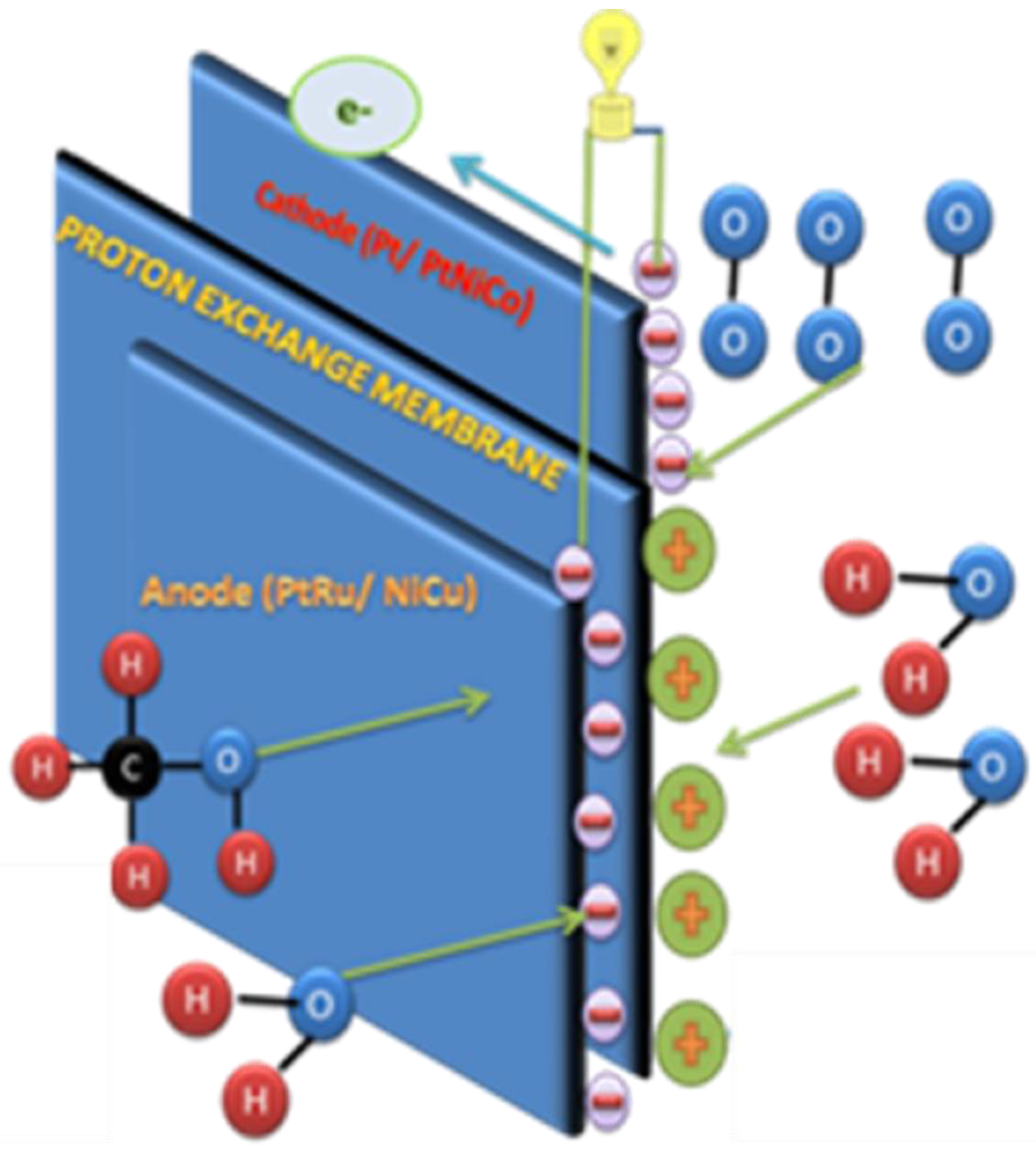
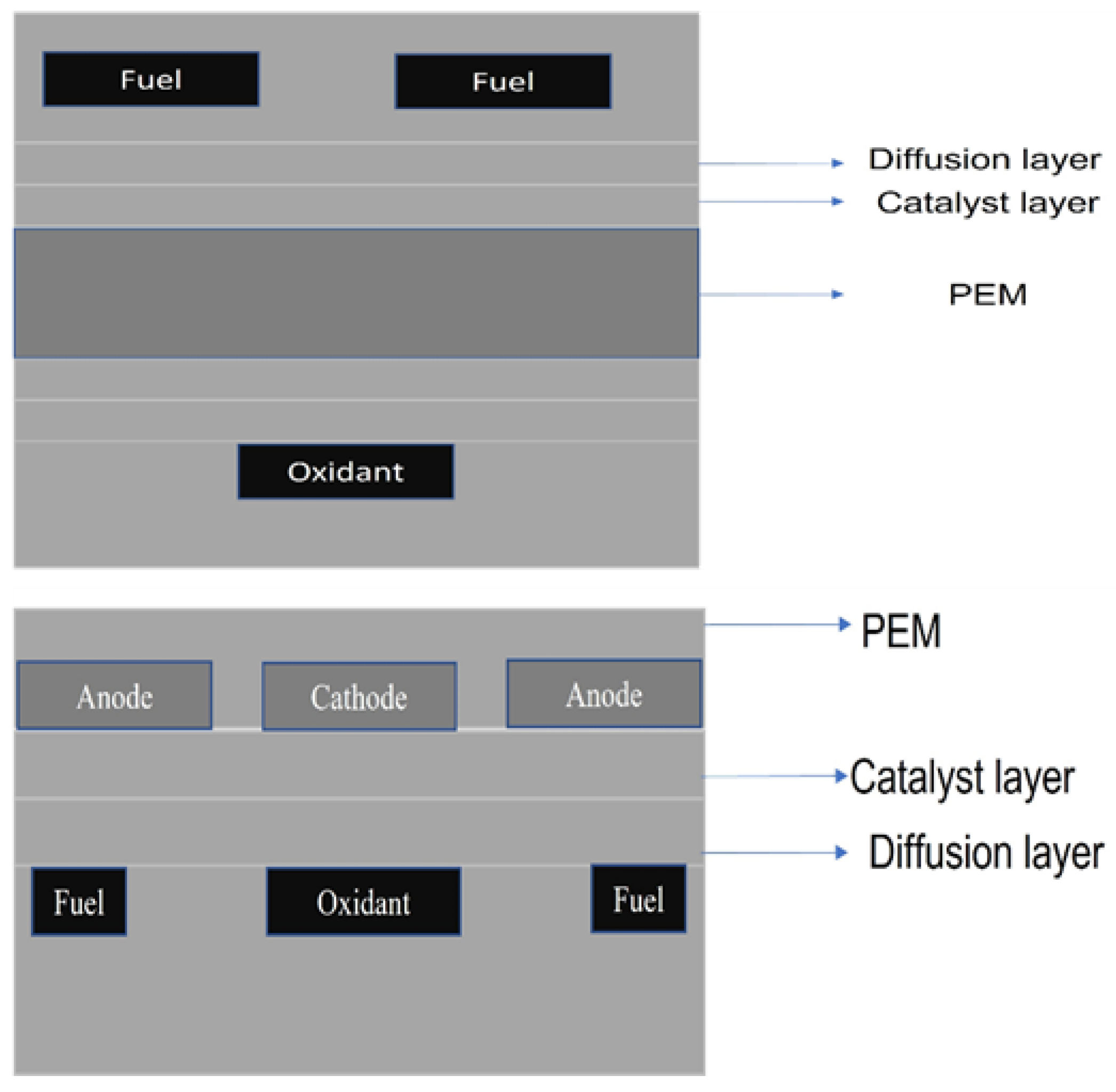
2. Fundamental and Design Consideration

Fuel cells comprise an anode, cathode, and electrolyte. An anode obtains fuel, such as methanol, whereas the cathode obtains air. In a methanol fuel cell, a catalyst in the anode breaks down methanol into formate and e, and these e travel in opposite directions to the cathode, as shown in Figure 1.
Figure 2 illustrates the fuel cell components such as the polymer membrane, electrodes, bipolar plates, gaskets, end plate, and methanol feed subsystem.

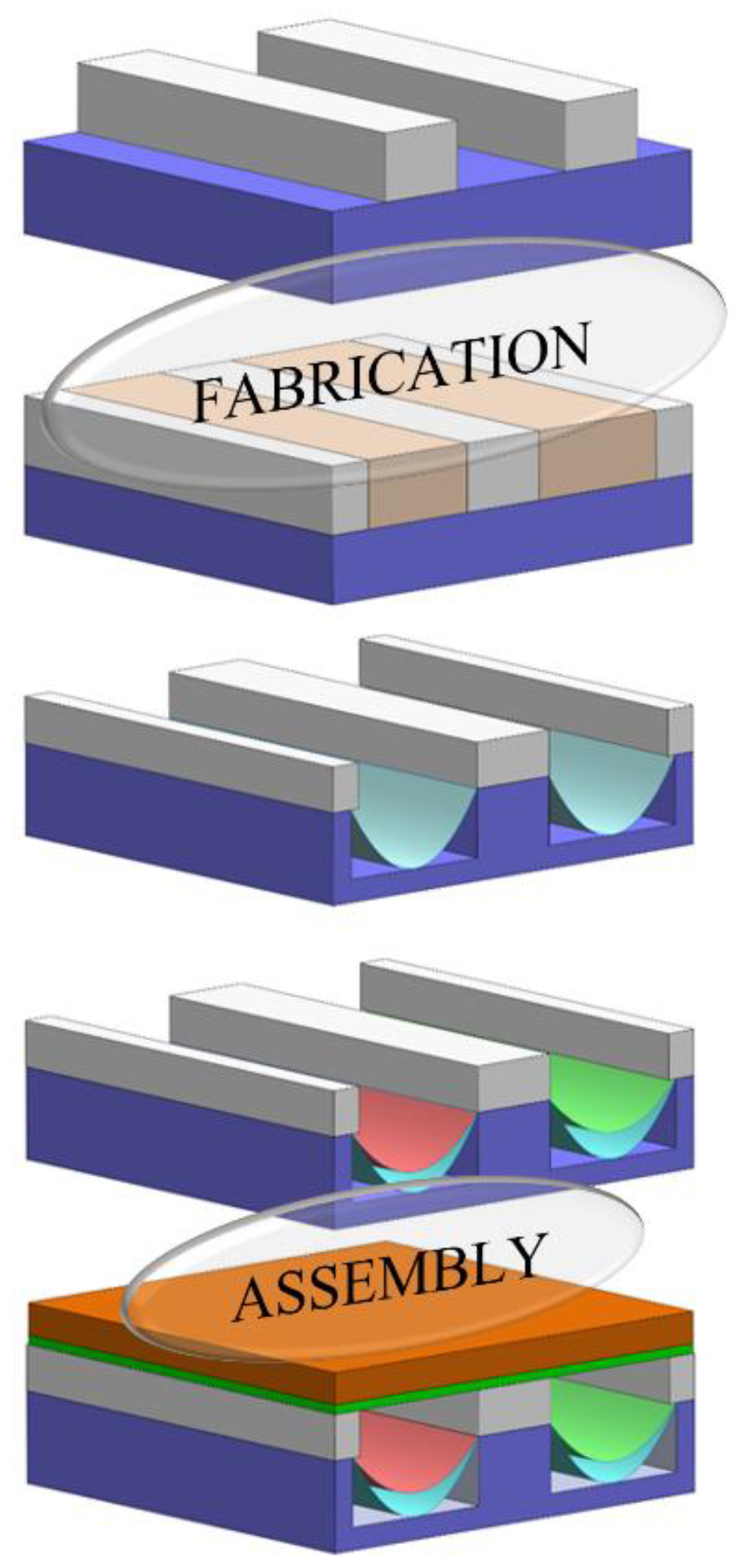
3. Methodology and Fabrication

Micro-DMFC devices are most commonly designed using micromachining, 3D printing, lithographic processes, and even hot embossing. Lithographic processes mainly include deep reactive ion etching, chemical vapor deposition, e-beam sputtering [12], radio frequency (RF) sputtering, etc. Other lithography techniques such as etching, micromachining, laser machining, and hot embossing also have been used in previous reports.
To date, researchers have mainly used graphite, though a few have also reported using stainless steel and silicon substrates. Wang et al. created a μDMFC using a silicon substrate as a stack, achieving about 2.52 mW power density [14,16]. Nowadays, researchers have started to use stainless steel as a substrate due to its conductivity and strength. Studies have recently focused on creating flexible DMFCs due to the appeal of DMFCs’ high energy density and the promotion of wearable technology. A study by Kamitani et al. (2009) investigates the use of a hydrophilic macroporous layer in microchannel direct methanol fuel cells (µDMFCs) to improve fuel utilization efficiency [17]. The addition of this macroporous layer enhances the distribution and diffusion of methanol within the microchannels, reducing the risk of fuel starvation and improving the overall fuel efficiency. The results show that the macroporous layer helps to maintain better contact between the methanol fuel and the catalyst, leading to more effective fuel oxidation and improved performance in µDMFCs. This design modification optimizes fuel use, thereby enhancing the efficiency of the system [17]. For example, Zhang et al. and Hsu et al. demonstrated flexible substrates including graphite, glass, plastic film, and metal to design and fabricate flexible anode structures for micro-DMFCs [18,19]. Other research teams focused on flexible electrodes and attempted to combine them with gold wire and polymer to create current collectors that hold slight contact resistance. A study by Chang et al. specified that there was lesser bonding between a Polydimethylsiloxane (PDMS) substrate and that the flexibility was also drained [20]. Tominaka et al. developed a flexible on-chip fuel cell using propylene materials and printed circuit techniques. However, most of the previous work has only focused on the flexible components of μDMFCs and the assembly method, which is given in Figure 3.
Heat transfer has been studied and found to be excellent and uniform in silicon and stainless steel compared with polymers, as shown in Table 1. In the case of polymers, the heat dissipation is not uniformly distributed. This might affect the system stability and efficiency.

4. Fuel Delivery System

In μDMFCs, the fuel supply is the major process, and is mainly performed by two flows, either an active flow or passive flow. An active flow needs an external source of energy to pump the fuel, such as a fan, blower, etc. Kamitani et al. (2008) designed a DMFC in a silicon substrate and obtained a maximum power of 275 mW/cm2 [24]. Passive systems exclude any external sources, and use capillary forces and diffusion. Hashim et al. designed both single and multiple passive stacks and obtained a maximum power of 12 mW/cm2 [25,26]. Self-breathing was performed by Liu et al. using stainless steel as a substrate, while Wang et al. used a silicon substrate, achieving power densities of about 24.7 mW/cm2 and 34.2 mW/cm2. The flow systems are compared in Table 2.

5. Flow Field Designs

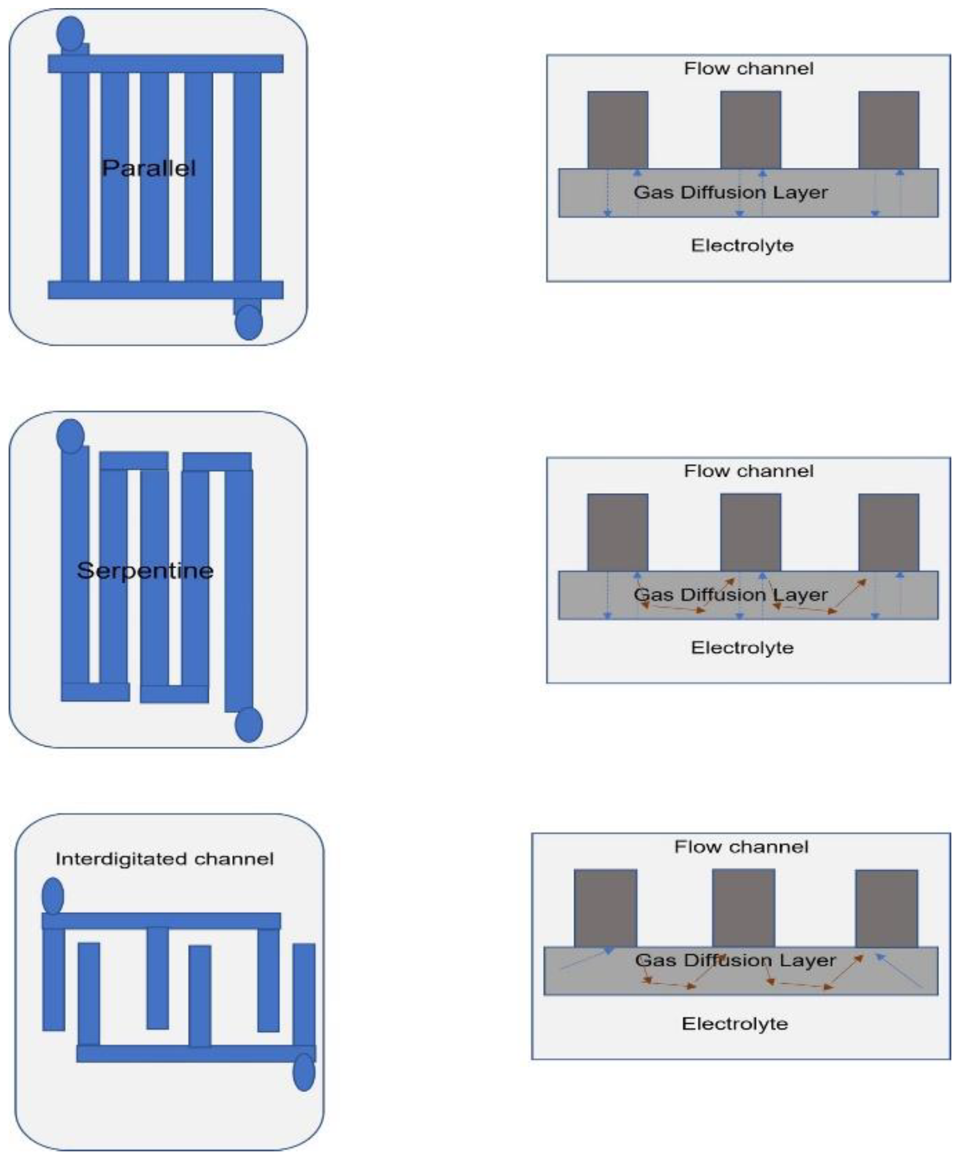
5.1. Planar and Bipolar Designs

Micro-DMFCs perform based on the flow plate incorporated with the membrane. The two designs that are still stabilized are bipolar and planar. Planar design usually works in one orientation. Bipolar plates usually connect, and they also separate the individual fuel cells in series to create a fuel stack with the required potential and facilitate the even distribution of gas and oxygen (Figure 4). Bipolar and planar plates are designed as follows:
Tominaka et al. demonstrated new structures for micro fuel cells in chip power source which are simple in design. Planar fuel cells are highly attractive due to their ease of prototyping and simplified design [12]. The flow field is designed as channels arranged in a specific pattern, covering the entire area, often incorporating porous erections. There are three types of flow fields: parallel, serpentine, and interdigitated (Figure 5).
Ho Chang et al. demonstrated the lithography used to print the flow field on a DMFC. In their study, they used a bipolar plate as a Printed Circuit Board (PCB) plate where the electrocatalyst was deposited directly on the PCB [36]. A lithography process was also used to fabricate serpentine flow fields on the PCB. Serpentine outlines (single or double) were used in most reports. Flow field designs play a crucial role in shaping polarization curves and overpotential losses. Their impact on mass transport, activation losses, and ohmic resistance has been further elaborated. Different configurations can either enhance or hinder electrochemical reactions. For example, interdigitated flow fields improve mass transport, reducing activation losses and enhancing voltage output.

5.1.1. Concentration Overpotential

Inefficient flow field designs can cause uneven reactant distribution, leading to concentration overpotentials. Parallel flow fields are particularly susceptible, as water accumulation can obstruct reactant flow, increasing losses and reducing efficiency. Uneven distribution prevents certain catalyst regions from functioning effectively, causing variations in current density. In parallel flow configurations, reactants move in the same direction along the channels. While simple in design, this layout often struggles with water buildup, which blocks methanol and oxygen flow, limiting reactant availability and cell performance.

5.1.2. Ohmic Resistance

This arises from charge transport resistance within fuel cell components and significantly affects DMFC efficiency. Serpentine flow fields (SFFs) tend to have higher internal resistance due to inefficient ionic transport and lower membrane hydration. In contrast, interdigitated flow fields (IFFs) enhance water transport, improving membrane hydration and reducing ionic resistance, thereby boosting overall performance.

5.2. Bioinspired Flow Fields

Hwang et al. investigated the serpentine flow field effect for a single DMFC performance, and this design delivered excellent performance compared to the parallel flow field. They improved the performance of a bipolar plate by optimizing the channel dimension and shape. When the channel depth declined, the cell performance remained constant [37]. The lesser channel depth was effective for elevating the direct velocity of reactants and products. Furthermore, the pressure drops and cell linear velocity were determined by using a computational fluid dynamics (CFD) technique.
To increase electrochemical performance, bioinspired flow fields have been explored. Murray’s Law determines the dimensions of the parental channel to the offspring channels. Guo et al. developed a series of flow fields inspired by the fractal structure of a tree leaf, using Murray’s Law to estimate the channel dimensions in their bioinspired designs. Similarly, Zografos et al. predicted the optimal proportional relationship between the diameters of parent and daughter vessels in networks characterized by circular cross-sections [38]. Kloess et al. presented two different novel structures: leaf and lung designs. These types of designs combine the advantages of the mixed serpentine and interdigitated patterns. They performed both experimental and simulation testing to study the effect of the novel flow channel patterns. The flow diffusion was found to be more uniform for the novel flow channel patterns. A fuel cell of about 25 cm2 was assembled and tested for different flow fields such as leaf, lung, serpentine, and interdigitated fields. The improvements in peak power density shown by both the leaf and lung designs were up to 30% [39].
A study by Ghadhban et al. explored the impact of bio-flow field configurations on Proton Exchange Membrane (PEM) fuel cells. The experiments were conducted using a PROTIUM-150-type PEM fuel cell, which has a total of six cells and a rated power output of 150 W (10 A @ 15 V), with a voltage range from 15 V to 23 V. The results showed that the leaf vein FF design outperformed both the single serpentine design and the tree shape design. Specifically, the leaf vein configuration enhanced the performance of the PEMFC by 5.12% compared to the serpentine design and 3.75% compared to the tree shape design. This study highlights how bioinspired flow field designs can improve the efficiency and overall performance of PEM fuel cells, potentially offering a more effective approach compared to traditional flow field configurations [40].

6. Parameters for Effective Systems

6.1. Methanol Concentration

The performance of DMFCs can be influenced by the concentration of methanol through two phenomena: (i) increments in methanol concentration, and (ii) increases in gradient concentration between the anode and the cathode side where methanol crosses over across the Nafion membrane, which can also indirectly enhance the performance of DMFCs. Researchers have evaluated cell performance with different concentrations of methanol [41]. The best performance was obtained for a 4 M methanol concentration, with excellent power density and better stability. In a study by Feng, Liu, and Yang (2017), a selective electrocatalyst-based DMFC was developed to operate effectively at high concentrations of methanol [42]. This research specifically addresses the challenges of methanol crossover and poor performance at higher concentrations by utilizing a highly selective electrocatalyst. The experiments showed that the DMFC achieved a peak power density of 85 mW/cm2 at 4 M methanol concentration. The cell maintained stable operation with a current density of 220 mA/cm2 under these high-concentration conditions, which is a significant improvement compared to traditional DMFCs that struggle with higher methanol concentrations. The study demonstrated that the use of selective electrocatalysts can enhance fuel cell performance and mitigate the effects of methanol crossover, ultimately improving the efficiency of DMFCs at high methanol concentrations [42].

6.2. Effect of Temperature

The major challenge of DMFC fabrication is the optimization of temperature and heat. Most DMFC applications are portable. As such, researchers are trying to create devices that operate at room temperature, but some previous reports show that an increase in temperature enhances the performance and the mass transfer rate [43,44]. Kamarudin et al. clearly state that the heat produced should be self-sustaining or accumulated. Hsieh et al. concluded that a uniform temperature can be obtained for straight channels [45]. So, the optimized temperature should be obtained and heat should be dissipated uniformly through the cell.

6.3. Effect of Gas Pressure

When oxygen gas pressure is increased, it directly improves oxygen diffusion to the catalyst layer, enhancing reaction kinetics. The pressure must be high enough to ensure uniform oxygen supply across the entire cathode. Ribs help channel the flow but also reduce flow in certain areas, maintaining pressure and ensuring uniform oxygen distribution. In DMFCs, the operating oxygen pressure varies depending on the system design, as they are more susceptible to methanol crossover. The cathode gas pressure in DMFCs is crucial for efficient oxygen supply and reducing methanol crossover. Typically, oxygen is supplied at pressures between 1.5 and 3 bar, which ensures uniform distribution under the ribs and enhances the oxygen reduction reaction. Higher pressure helps mitigate methanol crossover, improving overall performance. The optimal pressure depends on the fuel cell design and desired output.

6.4. Effect of Catalyst Loadings

Hashim et al. used an aqueous form of a methanol solution, nearly 4 M in concentration. In their study, all tests were conducted at room temperature in a passive cell mode, meaning no auxiliary equipment was attached to the PEM fuel cell during the experiments. The Open Circuit Voltage (OCV) and performance data were measured using an electronic load system (Prodigit 3315D), operating in constant current (CC) mode. Initially, a methanol solution was injected into the cell, and the OCV data were recorded as the voltage stabilized. Once the OCV became stable, the performance of the microcell was assessed by applying a current to the cell and measuring its response. This setup ensured that the impact of the different bioinspired FF configurations on the fuel cell’s performance was accurately captured under controlled conditions [26]. The performance of various anode and cathode catalysts with different loadings has been compared in Table 3.

6.5. Effect of Orientation

Wu et al. conducted experiments to analyze flexible μDMFCs in three different orientations: vertical, horizontal, and inverted horizontal. The tests were performed using 50% methanol solutions in passive mode. In the vertical orientation, the μDMFC achieved the highest power density of 15.3 mW/cm2. In this orientation, the methanol fuel flows from top to bottom, with the driving force being a combination of capillary force and gravity. In the horizontal orientation, when the μDMFC was oriented horizontally, the power density dropped to 14.1 mW/cm2. In this configuration, the capillary force and gravity both act in parallel, leading to a decrease in the fuel flow efficiency. In the inverted horizontal orientation, even with the fuel tank facing downwards, the μDMFC still managed to maintain a power density of 13.2 mW/cm2. In this case, the capillary-driven force opposes gravity, making the fuel flow more challenging, but the system still showed decent performance. These results indicate that the vertical orientation, where capillary forces and gravity work together, provides the highest performance, while the inverted horizontal orientation, which opposes these forces, still retains a reasonable power density despite the reduced efficiency [48].

7. Performance Analysis

The micro-DMFC reported is the Nafion 117. Though active fuel cells have good performance, most interestingly, passive fuel cells are used in portable applications. The best substrates are silicon and stainless steel based on the majority of reports, but for innovations in flexible electrodes, polymers are more feasible.

8. Cost Analysis

Despite the progress in novel materials and manufacturing techniques, μDMFCs have not yet been widely adopted as alternatives to battery technologies. A number of studies have addressed the global costs of DMFC or micro-DMFC systems in comparison to traditional power sources, like lithium-ion batteries. Hockaday et al. compared a micro-DMFC using a new design that incorporates vacuum deposition techniques for mass production with a lithium-ion battery. They noted that an acceptable cost for small power devices should be around USD 100/W. Based on their analysis, the cost of the micro-DMFC was found to be well below this level, making it a potentially cost-effective alternative. In another study, Apanel et al. reviewed the design of a DMFC engineering concept for mobile applications. Their analysis concluded that the cost of DMFCs for cell phones and small portable generators was lower than that of conventional power technologies. They emphasized that the competitive cost of DMFC technology was largely driven by the large market size and the economies of scale that could be realized with mass production. Overall, while μDMFC technology holds potential, particularly in mobile applications, its widespread adoption has been hindered by challenges in manufacturing scale, cost reduction, and market penetration. However, the competitive cost dynamics presented in these studies suggest that with further development and economies of scale, DMFC technology could become a viable alternative in certain niches [49,50,51,52]. A parametric study comparing the costs of a Li-ion battery and a DMFC system for powering a laptop, camcorder, and cell phone over a 4-year operational period found that the Li-ion battery is initially cheaper in the first year. However, by the end of the 4-year period, the DMFC system becomes more cost-effective. This is because while Li-ion batteries degrade over time and require more frequent replacements, DMFC systems have a longer lifespan and incur lower maintenance or replacement costs, making them more economical in the long run [53].

9. Advanced Applications

At the FC Expo 2009, Sony introduced a hybrid power system combining a battery and DMFC for power cordless speakers and mobile phone chargers. The fuel cell was slim, only 15 mm thick, with a 15 W output. In 2008, MTI Micro unveiled the Mobion external power pack, featuring a detachable cartridge that provided 25 Wh of portable power, offering nearly 25 h. These innovations showed potential for integrating DMFCs with portable devices for extended and efficient power solutions [54,55].

10. Numerical Analysis

PEMFC performance is greatly influenced by the design of the flow field and surface phenomena. It is crucial to comprehend the impact of the wettability and contact angle of the droplet in the flow field to increase the water balance and uniformity of the fuel distribution in the flow field. Numerical simulation is one of the effective methods for improving PEMFCs’ functional parameters to enhance the device performance. Recently, a few researchers have compared their unique channel design to the currently existing conventional design. A unique hydrophilic channel surface was employed to draw water away from the GDL’s hydrophobic surface using the volume of fluids (VOF) approach, and this was achieved with a very small contact angle [56]. The use of VOF is heavily prevalent in PEMFC simulations due to the restriction of the hydrophobic surface water-sliding properties by the no-slip condition in GDLs [57,58,59,60]. Surface wettability was improved in the VOF model by integrating sliding angle and static contact angles and demonstrated by including wall shear stress. The microstructure of the GDL, which is closely related to the surface roughness created by a sequence of rectangular ribs to simulate the surface roughness, has a greater effect on the behavior [61]. The intersectant flow field has been designed to determine the performance of FCs and study parameters such as current density, the distribution of oxygen at the reaction contact, and the distribution of water mass in the innovative flow field [62].
Maslan et al. [63] envisaged the dissemination of various behaviors to study DMFC performance. Their report clarifies the systematic and specified geometry and flow rate of air. Additionally, they made assumptions such as a laminar fluid flow, incompressible, isothermal, isotropic, and the completely hydrated state of the membrane. Their findings show that the addition of a tapered and sloped structure can enhance the efficacy of droplets in flow channel. This decreases the maximum droplet removal time of the new channel by 24.4% when compared to conventional flow channels [64]. A novel straight-zigzag flow was modeled to significantly boost the water expulsion rate at the cathode flow outlet, which in turn increased the proton conductivity across the membrane electrolyte [65]. Similarly, using a bionic flow field can enhance the uniformity of the flow field. The asymmetric bionic flow channel has the best PEMFC performance. The simulation’s results demonstrate that gravity significantly affects the movement and processing of liquid water in the bionic flow channel [66]. On the other hand, mechanical aspects such as clamping plate compression have improved power density by reducing contact resistance between PEMFC components, and at 4389 N the performance was decreased because of GDL deformation [67]. Figure 6 presents the schematics of the prominently used flow field designs.
Vasile et al. [68] have optimized the channel length, channel width, GDL porosity, and GDL permeability. Their study utilized a 3D Multiphysics, multi-component, single-phase, and isothermal model. The electrochemical behavior and fluid dynamics were performed using Maxwell–Stefan, Stokes–Brinkman, and Tafel equations. The 3D model was constructed by the Stokes–Brinkman porous equation. Shyu and Hung [69] have studied the performance of the flow field effect of a membraneless direct formic acid fuel cell. Their assumptions included steady-state, isothermal, laminar, incompressible, and homogenous electrodes, dilute and thoroughly mixed solutions, electromigration transfer, dissolved CO2, and diffusion. Formate ion migration was not considered due to the high concentration of the supporting electrolyte. They achieved a maximum power density of about 11.9 mW/cm2 and 11.5 mW/cm2 at air flow rates of 200 sccm and 500 sccm. The simulation results suggested that the Pin (0.8) air flow field could be the optimal design. Sharifi et al. [70] demonstrated the optimization of operational parameters for improving the performance of direct methanol fuel cells. Parameters such as power density, current density, cell temperature, methanol concentration, and oxygen flow rate were studied. The model investigated charge conservation, mass, momentum, methanol, and water and oxygen transport. Also, the concentration distributions of methanol and oxygen at the optimum operating conditions were studied. Jung et al. [71] developed a half-cell DMFC and demonstrated that in a parallel FF, the performance of the fuel cell was found to decline quickly; it was also found that the serpentine-type FF gave the best performance. Tang et al. [72] shaped a 3D, half-cell model to analyze four types of FFs (parallel, serpentine, parallel serpentine, and zigzag). Their results showed that the zigzag type of FF configuration generated the most significant concentration distribution.
Figure 6. Schematics of the prominent flow fields in PEFMCs. (a) Serpentine flow field [73], (b) constructable flow field [74], (c) pin structures [75], (d) biomimetic flow field [76], (e) 3D flow field [77], (f) parallel serpentine flow field [78], (g) tapered flow field [79], and (h) 3D fine mesh flow field [80].
Electrochem 06 00011 g006
Ramesh et al. [81] focused on the effect of channel width on micro fuel cell performance using 3D modeling. Vasile et al. [82] optimized the current density distribution on a single cell using layer-by-layer, progressive loadings for adjusting the anode catalyst. Also, their model evaluates electrochemical, fluid dynamics and thermal phenomena. Specifically, the Stokes–Brinkman equation describes the motions and hydrodynamic forces of the electrocatalyst. The model divulges the congruent and convergent data for a commercial 25 cm2 MEA which consists of Nafion®117, Pt/C at the cathode, and Pt:Ru at the anode. Also, they carried out the experiment at various temperatures and methanol concentrations to confirm. The obtained model was used to optimize the uniform current distribution over the catalytic layer and achieve a better cell performance. The cell was implemented in a 25 cm2 in-house three-layer MEA and tested for 26 h, showing better stability than a standard MEA. El-Zoheiry et al. [83] demonstrated a direct effect on the mass transport process of reactants from the flow channel toward the catalyst layer. They assumed high currents, low cell voltage, high reactant consumptions, and fast reactant supply. They solved it in four steps, examining current distributions, mass conservation and momentum conservation, flow velocities, and pressures. Govindavasu and Somasundaram [84] performed a numerical simulation and concluded that the optimal operating temperature of DMFCs is 333 K, for which maximum power density was obtained. They observed that the output voltage of the DMFCs increased steadily till the optimal cell temperature above which the voltage output is decreased due to the conditions in the cell drying out. Binyamin and Lim [85] studied the thermal contact resistance (TCR) and permeability of the GDL layer as a function of temperature distribution and current density. It was found that the maximum temperature distribution of 74.49 °C was recorded near the cathode catalysis layer, predominately due to the oxygen reduction process near the cathode [86,87].

11. Current Challenges and Future Direction

DMFCs face several challenges, including low efficiency, methanol crossover, high material costs, and limited durability. Methanol crossover reduces efficiency by allowing fuel to pass from the anode to the cathode, leading to unwanted reactions. Additionally, the use of platinum catalysts and the need for methanol storage infrastructure drive up costs. DMFCs also suffer from degradation due to catalyst poisoning and membrane wear, limiting their lifespan. Water management is another key concern for maintaining proton conductivity. Future advancements in DMFC technology include developing non-platinum catalysts, improving membranes to reduce methanol crossover, optimizing system performance and water management, and integrating methanol reforming to enhance fuel efficiency. Efforts are also being made to miniaturize and integrate DMFCs for portable electronics and explore alternative fuels, such as ethanol, to increase sustainability. Overcoming these challenges will be essential for DMFCs to become a more competitive and reliable power source.

12. Conclusions

Market trends for trans electronic devices indicate a substantial demand for portable power systems with high power density. To compete with lithium-based rechargeable batteries, DMFCs are currently dominating the portable power market. High-concentration methanol solutions, including pure methanol, should be stored in the fuel reservoir to leverage their high energy density. Micro-DMFC performance mainly depends on the flow field and oxidant and fuel delivery systems. So, there should be a thorough understanding of the design to make it efficient. Due to the involvement of flow fields, mathematical modeling is needed. Further, to design an efficient micro-DMFC, it is a must to develop internal conditions perfectly throughout the system. There is a necessity to obtain optimum conditions to achieve maximum efficiency and excellent power density.

Author Contributions

D.C.S.: Conceptualization; Methodology; Software; Writing—Original Draft. G.N.: Writing—Review and Editing. S.R.: Review and Editing. K.V.: Conceptualization; Methodology; Software; Writing—Review and Editing. S.S.: Methodology; Software. S.E.M.: Methodology; Software; Writing—Review and Editing. K.K.: Methodology; Software; Writing—Review and Editing; Funding Acquisition. All authors have read and agreed to the published version of the manuscript.

Funding

This research received no external funding.

Institutional Review Board Statement

Not applicable.

Informed Consent Statement

Not applicable.

Data Availability Statement

The original contributions presented in the study are included in the article; further inquiries can be directed to the first/corresponding author.

Acknowledgments

Divya Catherin Sesu (DSC) is grateful to Ariel University for offering a postdoctoral fellowship.

Conflicts of Interest

The authors declare no conflicts of interest.

References

  1. Choban, E.R.; Markoski, L.J.; Wieckowski, A.; Kenis, P.J. Microfluidic fuel cell based on laminar flow. J. Power Sources 2004, 128, 54–60. [Google Scholar] [CrossRef]
  2. Jung, D.H.; Lee, C.H.; Kim, C.S.; Shin, D.R. Performance of a direct methanol polymer electrolyte fuel cell. J. Power Sources 1998, 71, 169–173. [Google Scholar] [CrossRef]
  3. O’Hayre, R.; Fabian, T.; Litster, S.; Prinz, F.B.; Santiago, J.G. Engineering model of a passive planar air breathing fuel cell cathode. J. Power Sources 2007, 167, 118–129. [Google Scholar] [CrossRef]
  4. Falcão, D.S.; Oliveira, V.B.; Rangel, C.M.; Pinto, A.M.F.R. Review on micro-direct methanol fuel cells. Renew. Sustain. Energy Rev. 2014, 34, 58–70. [Google Scholar] [CrossRef]
  5. Fachini, E.R.; Diaz-Ayala, R.; Casado-Rivera, E.; File, S.; Cabrera, C.R. Surface coordination of ruthenium clusters on platinum nanoparticles for methanol oxidation catalysts. Langmuir 2003, 19, 8986–8993. [Google Scholar] [CrossRef]
  6. Chen, T.Y.; Lee, G.W.; Liu, Y.T.; Liao, Y.F.; Huang, C.C.; Lin, D.S.; Lin, T.L. Heterojunction confinement on the atomic structure evolution of near monolayer core–shell nanocatalysts in redox reactions of a direct methanol fuel cell. J. Mater. Chem. A 2015, 3, 1518–1529. [Google Scholar] [CrossRef]
  7. Yang, W.M.; Chou, S.K.; Shu, C. Effect of current-collector structure on performance of passive micro direct methanol fuel cell. J. Power Sources 2007, 164, 549–554. [Google Scholar] [CrossRef]
  8. Motokawa, S.; Mohamedi, M.; Momma, T.; Shoji, S.; Osaka, T. MEMS-based design and fabrication of a new concept micro direct methanol fuel cell (μ-DMFC). Electrochem. Commun. 2004, 6, 562–565. [Google Scholar] [CrossRef]
  9. Baldauf, M.; Preidel, W. Status of the development of a direct methanol fuel cell. J. Power Sources 1999, 84, 161–166. [Google Scholar] [CrossRef]
  10. Lu, G.Q.; Wang, C.Y.; Yen, T.J.; Zhang, X. Development and characterization of a silicon-based micro direct methanol fuel cell. Electrochim. Acta 2004, 49, 821–828. [Google Scholar] [CrossRef]
  11. Zhang, Q.; Wang, X.; Zhong, L.; Zhou, Y.A.; Qiu, X.; Liu, L. Design, optimization and microfabrication of a micro-direct methanol fuel cell with microblocks in anode structure. Sens. Actuators A 2009, 154, 247–254. [Google Scholar] [CrossRef]
  12. Tominaka, S.; Ohta, S.; Obata, H.; Momma, T.; Osaka, T. On-chip fuel cell: Micro direct methanol fuel cell of an air-breathing, membraneless, and monolithic design. J. Am. Chem. Soc. 2008, 130, 10456–10457. [Google Scholar] [CrossRef] [PubMed]
  13. Abrego-Martínez, J.C.; Moreno-Zuria, A.; Wang, Y.; Cuevas-Muñiz, F.M.; Arriaga, L.G.; Sun, S.; Mohamedi, M. Fabrication and evaluation of passive alkaline membraneless microfluidic DMFC. Int. J. Hydrogen Energy 2017, 42, 21969–21975. [Google Scholar] [CrossRef]
  14. Wang, X.; Zhang, Q.; Zhu, Y.; Liu, L. An air-breathing micro direct methanol fuel cell stack employing a single shared anode using silicon microfabrication technologies. J. Micromech. Microeng. 2009, 19, 094012. [Google Scholar] [CrossRef]
  15. Zhong, L.; Wang, X.; Jiang, Y.; Zhang, Q.; Qiu, X.; Zhou, Y.A.; Liu, L. A micro-direct methanol fuel cell stack with optimized design and microfabrication. Sens. Actuators A 2008, 143, 70–76. [Google Scholar] [CrossRef]
  16. Zhang, Q.; Wang, X.; Zhu, Y.; Zhou, Y.A.; Qiu, X.; Liu, L. Optimized temperature control system integrated into a micro direct methanol fuel cell for extreme environments. J. Power Sources 2009, 192, 494–501. [Google Scholar] [CrossRef]
  17. Kamitani, A.; Morishita, S.; Kotaki, H.; Arscott, S. Improved fuel use efficiency in microchannel direct methanol fuel cells using a hydrophilic macroporous layer. J. Power Sources 2009, 187, 148–155. [Google Scholar] [CrossRef]
  18. Zhang, H.; Hsing, I.M. Flexible graphite-based integrated anode plate for direct methanol fuel cells at high methanol feed concentration. J. Power Sources 2007, 167, 450–454. [Google Scholar] [CrossRef]
  19. Hsu, F.K.; Lee, M.S.; Lin, C.C.; Lin, Y.K.; Hsu, W.T. A flexible portable proton exchange membrane fuel cell. J. Power Sources 2012, 219, 180–187. [Google Scholar] [CrossRef]
  20. Chang, I.; Lee, M.H.; Lee, J.H.; Kim, Y.S.; Cha, S.W. Air-breathing flexible polydimethylsiloxane (PDMS)-based fuel cell. Int. J. Precis. Eng. Manuf. 2013, 14, 501–504. [Google Scholar] [CrossRef]
  21. Liu, X.; Zhang, B.; Zhang, Y.; He, H.; Li, J.; Wang, S.; Yuan, Z.; Deng, H. Development and characterization of a novel air-breathing micro direct methanol fuel cell stack for portable applications. J. Micromech. Microeng. 2010, 20, 104008. [Google Scholar] [CrossRef]
  22. Shen, M.; Walter, S.; Gijs, M.A.M. Monolithic micro-direct methanol fuel cell in polydimethylsiloxane with microfluidic channel-integrated Nafion strip. J. Power Sources 2009, 193, 761–765. [Google Scholar] [CrossRef]
  23. Sun, L.; Liu, C.; Liang, J.; Zhu, X.; Cui, T. A self-pumping and self-breathing micro direct methanol fuel cell with polymer bipolar plates. J. Power Sources 2011, 196, 7533–7540. [Google Scholar] [CrossRef]
  24. Kamitani, A.; Morishita, S.; Kotaki, H.; Arscott, S. Miniaturized microDMFC using silicon microsystems techniques: Performances at low fuel flow rates. J. Micromech. Microeng. 2008, 18, 125019. [Google Scholar] [CrossRef]
  25. Torres, N.; Santander, J.; Esquivel, J.P.; Sabaté, N.; Figueras, E.; Ivanov, P.; Fonseca, L.; Gràcia, I.; Cané, C. Performance optimization of a passive silicon-based micro-direct methanol fuel cell. Sens. Actuators B 2008, 132, 540–544. [Google Scholar] [CrossRef]
  26. Hashim, N.; Kamarudin, S.K.; Daud, W.R.W. Design, fabrication and testing of a PMMA-based passive single-cell and a multi-cell stack micro-DMFC. Int. J. Hydrogen Energy 2009, 34, 8263–8269. [Google Scholar] [CrossRef]
  27. Meng, D.D.; Kim, C.J. An active micro-direct methanol fuel cell with self-circulation of fuel and built-in removal of CO2 bubbles. J. Power Sources 2009, 194, 445–450. [Google Scholar] [CrossRef]
  28. Esquivel, J.P.; Sabaté, N.; Santander, J.; Torres, N.; Cané, C. Fabrication and characterization of a passive silicon-based direct methanol fuel cell. J. Microsyst. Technol. 2008, 14, 535–541. [Google Scholar] [CrossRef]
  29. Faria, L.; Barragán, V. Optimizing Methanol Flow Rate for Enhanced Semi-Passive Mini-Direct Methanol Fuel Cell Performance. Preprints 2025, 2025010827. [Google Scholar] [CrossRef]
  30. Ghayor, R.; Shakeri, M.; Sedighi, K.; Farhadi, M. Experimental and numerical investigation on passive and active μDMFC. Int. J. Hydrogen Energy 2010, 35, 9329–9337. [Google Scholar] [CrossRef]
  31. Esquivel, J.P.; Senn, T.; Hernández-Fernández, P.; Santander, J.; Lörgen, M.; Rojas, S.; Löchel, B.; Cané, C.; Sabaté, N. Towards a compact SU-8 micro-direct methanol fuel cell. J. Power Sources 2010, 195, 8110–8115. [Google Scholar] [CrossRef]
  32. Wang, S.J.; Huo, W.W.; Zou, Z.Q.; Qiao, Y.J.; Yang, H. Computational simulation and experimental evaluation on anodic flow field structures of micro direct methanol fuel cells. Appl. Therm. Eng. 2011, 31, 2877–2884. [Google Scholar] [CrossRef]
  33. Zhang, Y.; Zhang, P.; Yuan, Z.; He, H.; Zhao, Y.; Liu, X. A tapered serpentine flow field for the anode of micro direct methanol fuel cells. J. Power Sources 2011, 196, 3255–3259. [Google Scholar] [CrossRef]
  34. Zhang, Y.; Yuan, Z.; Li, Y.; Jia, Q.; Chen, S.; Liu, X. Design and fabrication of a silicon-based direct methanol fuel cell with a new cathode spoke structure. J. Power Sources 2011, 196, 3015–3025. [Google Scholar] [CrossRef]
  35. Nguyen, N.T.; Chan, S.H. Micromachined polymer electrolyte membrane and direct methanol fuel cells—A review. J. Micromech. Microeng. 2006, 16, R1. [Google Scholar] [CrossRef]
  36. Chang, H.; Kao, M.-J.; Chen, C.-H.; Cho, K.-C.; Hsu, C.-Y.; Chen, Z.-L. The Fabrication of Flow Field Plates for Direct Methanol Fuel Cell Using Lithography and Radio Frequency Sputtering. J. Nanosci. Nanotechnol. 2015, 15, 6172–6175. [Google Scholar] [CrossRef]
  37. Hwang, S.Y.; Joh, H.I.; Scibioh, M.A.; Lee, S.Y.; Kim, S.K.; Lee, T.G.; Ha, H.Y. Impact of cathode channel depth on performance of direct methanol fuel cells. J. Power Sources 2008, 183, 223–226. [Google Scholar] [CrossRef]
  38. Zografos, K.; Barber, R.W.; Emerson, D.R.; Oliveira, M.S. A design rule for constant depth microfluidic networks for power-law fluids. Microfluid. Nanofluidics 2015, 19, 737–749. [Google Scholar] [CrossRef]
  39. Kloess, J.P.; Wang, X.; Liu, J.; Shi, Z.; Guessous, L. Investigation of bio-inspired flow channel designs for bipolar plates in proton exchange membrane fuel cells. J. Power Sources 2009, 188, 132–140. [Google Scholar] [CrossRef]
  40. Ghadhban, S.A.; Alawee, W.H.; Dhahad, H.A. Study effects of bio-inspired flow filed design on Polymer Electrolyte Membrane fuel cell performance. Case Stud. Therm. Eng. 2021, 24, 100841. [Google Scholar] [CrossRef]
  41. Chen, C.Y.; Yang, P. Performance of an air-breathing direct methanol fuel cell. J. Power Sources 2003, 123, 37–42. [Google Scholar] [CrossRef]
  42. Feng, Y.; Liu, H.; Yang, J. A selective electrocatalyst–based direct methanol fuel cell operated at high concentrations of methanol. Sci. Adv. 2017, 3, e1700580. [Google Scholar] [CrossRef] [PubMed]
  43. Schulz, T.; Weinmüller, C.; Nabavi, M.; Poulikakos, D. Electrochemical impedance spectroscopy analysis of a thin polymer film-based micro-direct methanol fuel cell. J. Power Sources 2010, 195, 7548–7558. [Google Scholar] [CrossRef]
  44. Liu, J.G.; Zhao, T.S.; Liang, Z.X.; Chen, R. Effect of membrane thickness on the performance and efficiency of passive direct methanol fuel cells. J. Power Sources 2006, 153, 61–67. [Google Scholar] [CrossRef]
  45. Hsieh, S.S.; Her, B.S. Heat transfer and pressure drop in serpentine μDMFC flow channels. Int. J. Heat. Mass. Transf. 2007, 50, 5323–5327. [Google Scholar] [CrossRef]
  46. Tominaka, S.; Momma, T.; Osaka, T. Electrodeposited Pd-Co catalyst for direct methanol fuel cell electrodes: Preparation and characterization. Electrochim. Acta 2008, 53, 4679–4686. [Google Scholar] [CrossRef]
  47. Wu, Z.; Kuang, X.; Liu, L.; Wang, X. A flexible foldable tubular μDMFC for powering wearable devices. J. Microelectromech. Syst. 2017, 26, 1147–1154. [Google Scholar] [CrossRef]
  48. Rashidi, R.; Dincer, I.; Naterer, G.F.; Berg, P. Performance evaluation of direct methanol fuel cells for portable applications. J. Power Sources 2009, 187, 509–516. [Google Scholar] [CrossRef]
  49. Kamarudin, S.K.; Achmad, F.; Daud, W.R.W. Overview on the application of direct methanol fuel cell (DMFC) for portable electronic devices. Int. J. Hydrogen Energy 2009, 34, 6902–6916. [Google Scholar] [CrossRef]
  50. Apanel, G.; Johnson, E. Direct methanol fuel cells–ready to go commercial? Fuel Cells Bull. 2004, 2004, 12–17. [Google Scholar] [CrossRef]
  51. Xie, C.; Bostaph, J.; Pavio, J. Development of a 2 W direct methanol fuel cellpower source. J. Power Sources 2004, 136, 55–65. [Google Scholar] [CrossRef]
  52. Faghri, A.; Li, X.; Bahrami, H. Recent advances in passive and semi-passive direct methanol fuel cells. Int. J. Therm. Sci. 2012, 62, 12–18. [Google Scholar] [CrossRef]
  53. Chen, X.; Li, T.; Shen, J.; Hu, Z. From structures, packaging to application: A system-level review for micro direct methanol fuel cell. Renew. Sustain. Energy Rev. 2017, 80, 669–678. [Google Scholar] [CrossRef]
  54. Varcoe, J.R.; Beillard, M.; Halepoto, D.M.; Kizewski, J.P.; Poynton, S.; Slade, R.C. Membrane and electrode materials for alkaline membrane fuel cells. Ecs Trans. 2008, 16, 1819–1834. [Google Scholar] [CrossRef]
  55. Qin, Y.; Guo, Q.; Chen, R.; Zhuang, Y.; Wang, Y. Numerical investigation of water droplet impact on PEM fuel cell flow channel surface. Renewable 2021, 45, 29861–29873. [Google Scholar] [CrossRef]
  56. Ferreira, R.B.; Falcão, D.S.; Oliveira, V.B.; Pinto, A.M.F.R. Numerical simulations of two-phase flow in an anode gas channel of a proton exchange membrane fuel cell. Energy 2015, 82, 619–628. [Google Scholar] [CrossRef]
  57. Pugal Mani, S.; Kalaiyarasan, M.; Agilan, P.; Ravichandran, K.; Rajendran, N.; Meng, Y. Evaluation of anticorrosion and contact resistance behavior of poly(orthophenylenediamine)-coated 316L SS bipolar plate for proton exchange membrane fuel cell. Int. J. Hydrogen Energy 2022, 47, 41097–41110. [Google Scholar] [CrossRef]
  58. Guo, Q.; Qin, Y. Numerical investigation of water droplet removal characteristics in novel block channels of PEMFC using dynamic wettability model. Int. J. Hydrogen Energy 2021, 46, 36890–36902. [Google Scholar] [CrossRef]
  59. Carton, J.G.; Lawlor, V.; Olabi, A.G.; Hochenauer, C.; Zauner, G. Water droplet accumulation and motion in PEM (Proton Exchange Membrane) fuel cell mini-channels. Energy 2012, 39, 63–73. [Google Scholar] [CrossRef]
  60. Qin, Y.; Wang, X.; Chen, R.; Shangguan, X. Water transport and removal in PEMFC gas flow channel with various water droplet locations and channel surface wettability. Energies 2018, 11, 880. [Google Scholar] [CrossRef]
  61. He, G.; Yamazaki, Y.; Abudula, A. The effect of wall roughness on the liquid removal in micro-channels related to a proton exchange membrane fuel cell (PEMFC). J. Power Sources 2010, 195, 1561–1568. [Google Scholar] [CrossRef]
  62. Wen, D.H.; Yin, L.Z.; Piao, Z.Y.; Li, G.; Leng, Q.H. Performance investigation of proton exchange membrane fuel cell with intersectant flow field. Int. J. Heat. Mass. Transf. 2018, 121, 775–787. [Google Scholar] [CrossRef]
  63. Maslan, N.H.; Rosli, M.I.; Goh, C.W.; Masdar, M.S. Computational fluid dynamics simulation of the flow field of direct methanol fuel cells. Int. J. Mech. Mechatron. Eng. 2015, 15, 114–125. [Google Scholar]
  64. Lei, H.; Huang, H.; Li, C.; Pan, M.; Guo, X.; Chen, Y.; Liu, M.; Wang, T. Numerical simulation of water droplet transport characteristics in cathode channel of proton exchange membrane fuel cell with tapered slope structures. Int. J. Hydrogen Energy 2020, 45, 29331–29344. [Google Scholar] [CrossRef]
  65. Selvaraj, A.S.; Rajagopal, T.K.R. Numerical investigation on the effect of flow field and landing to channel ratio on the performance of PEMFC. Int. J. Energy Res. 2020, 44, 171–191. [Google Scholar] [CrossRef]
  66. Liu, S.; Chen, T.; Xie, Y.; Zhang, J.; Wu, C. Numerical simulation and experimental study on the effect of symmetric and asymmetric bionic flow channels on PEMFC performance under gravity. Int. J. Hydrogen Energy 2019, 44, 29618–29630. [Google Scholar] [CrossRef]
  67. Uzundurukan, A.; Bilgili, M.; Devrim, Y. Examination of compression effects on PEMFC performance by numerical and experimental analyses. Int. J. Hydrogen Energy 2020, 45, 35085–35096. [Google Scholar] [CrossRef]
  68. Vasile, N.S.; Videla, A.H.M.; Specchia, S. Effects of the current density distribution on a single-cell DMFC by tuning the anode catalyst in layers of gradual loadings: Modelling and experimental approach. Chem. Eng. J. 2017, 322, 722–741. [Google Scholar]
  69. Shyu, J.-C.; Hung, S.-H. Flow field effect on the performance of direct formic acid membraneless fuel cells: A numerical study. Processes 2021, 9, 746. [Google Scholar] [CrossRef]
  70. Sharifi, S.; Rahimi, R.; Mohebbi-Kalhori, D.; Colpan, C.O. Numerical investigation of methanol crossover through the membrane in a direct methanol fuel cell. Hydrog. Fuel Cell Energy Storage 2018, 5, 21–33. [Google Scholar]
  71. Jung, G.B.; Su, A.; Tu, C.H.; Lin, Y.T.; Weng, F.B.; Chan, S.H. Effects of cathode flow fields on direct methanol fuel cell-simulation study. J. Power Sources 2007, 171, 212–217. [Google Scholar] [CrossRef]
  72. Tang, Y.; Yuan, W.; Pan, M.; Wan, Z. Feasibility study of porous copper fiber sintered felt: A novel porous flow field in proton exchange membrane fuel cells. Int. J. Hydrogen Energy 2010, 35, 9661–9677. [Google Scholar] [CrossRef]
  73. Shang, K.; Han, C.; Jiang, T.; Chen, Z. Numerical study of PEMFC heat and mass transfer characteristics based on roughness interface thermal resistance model. Int. J. Hydrogen Energy 2023, 48, 7460–7475. [Google Scholar] [CrossRef]
  74. Tan, Q.; Lei, H.; Liu, Z. Numerical simulation analysis of the performance on the PEMFC with a new flow field designed based on constructal-theory. Int. J. Hydrogen Energy 2022, 47, 11975–11990. [Google Scholar] [CrossRef]
  75. Dang, D.K.; Zhou, B. Effects of pin shapes on gas-liquid transport behaviors in PEMFC cathode. J. Power Sources 2023, 557, 232584. [Google Scholar] [CrossRef]
  76. Huang, H.; Li, X.; Li, S.; Guo, X.; Liu, M.; Wang, T.; Lei, H. Evaluating the effect of refined flow channels in a developed biomimetic flow field on PEMFC performance. Energy 2023, 266, 126442. [Google Scholar] [CrossRef]
  77. Zhang, J.; Huang, P.; Ding, H.; Xin, D.; Sun, S. Investigation of the three-dimensional flow field for proton exchange membrane fuel cell with additive manufactured stainless steel bipolar plates: Numerical simulation and experiments. Energy 2023, 269, 126709. [Google Scholar] [CrossRef]
  78. Hamrang, A.; Abdollahzadeh, M.; Kermani, M.J.; Rahgoshay, S.M. Numerical simulation of the PEM fuel cell performance enhancement by various blockage arrangement of the cathode serpentine gas flow channel outlets/inlets. Int. J. Heat. Mass. Transf. 2022, 186, 122475. [Google Scholar] [CrossRef]
  79. Wang, Y.; Wang, X.; Fan, Y.; He, W.; Guan, J.; Wang, X. Numerical investigation of tapered flow field configurations for enhanced polymer electrolyte membrane fuel cell performance. Appl. Energy 2022, 306, 118021. [Google Scholar] [CrossRef]
  80. Bao, Z.; Niu, Z.; Jiao, K. Analysis of single-and two-phase flow characteristics of 3-D fine mesh flow field of proton exchange membrane fuel cells. J. Power Sources 2019, 438, 226995. [Google Scholar] [CrossRef]
  81. Ramesh, P.; Duttagupa, S.P. Effect of channel dimensions on micro-PEM fuel cell performance using 3D modeling. Int. J. Renew. Energy Res. 2013, 3, 353–358. [Google Scholar]
  82. Vasile, N.S.; Videla, A.H.M.; Simari, C.; Nicotera, I.; Specchia, S. Influence of membrane-type and flow field design on methanol crossover on a single-cell DMFC: An experimental and multi-physics modeling study. Int. J. Hydrogen Energy 2017, 42, 27995–28010. [Google Scholar] [CrossRef]
  83. El-Zoheiry, R.M.; Ookawara, S.; Ahmed, M. Efficient fuel utilization by enhancing the under-rib mass transport using new serpentine flow field designs of direct methanol fuel cells. Energy Convers. Manag. 2017, 144, 88–103. [Google Scholar] [CrossRef]
  84. Govindarasu, R.; Somasundaram, S. Studies on influence of cell temperature in direct methanol fuel cell operation. Processes 2020, 8, 353. [Google Scholar] [CrossRef]
  85. Binyamin, B.; Lim, O. Analyzing Temperature Distribution, Mass Transport, and Cell Performance in PEM Fuel Cells with Emphasis on GDL Face Permeability and Thermal Contact Resistance Parameters. ACS Omega 2023, 9, 1516–1534. [Google Scholar] [CrossRef] [PubMed]
  86. Kishore, S.C.; Perumal, S.; Atchudan, R.; Alagan, M.; Sundramoorthy, A.K.; Lee, Y.R. A Critical Review on Artificial Intelligence for Fuel Cell Diagnosis. Catalysts 2022, 12, 743. [Google Scholar] [CrossRef]
  87. Talukdar, A.; Chakrovorty, A.; Sarmah, P.; Paramasivam, P.; Kumar, V.; Yadav, S.K.; Manickkam, S. A Review on Solid Oxide Fuel Cell Technology: An Efficient Energy Conversion System. Int. J. Energy Res. 2024, 2024, 6443247. [Google Scholar] [CrossRef]
Figure 1. The reactions taking place at both sides of the fuel cell.
Electrochem 06 00011 g001
Figure 2. The design of (a) active and (b) passive DMFCs where the cathode end and the anode end are separated by the gasket and MEA membrane.
Electrochem 06 00011 g002
Figure 3. Fabrication and assembly of fuel cell by lithography.
Electrochem 06 00011 g003
Figure 4. Bipolar and planar designs [35].
Electrochem 06 00011 g004
Figure 5. The designs of different flow fields.
Electrochem 06 00011 g005
Table 1. Comparison with various substrates.
Substrate TypesFabrication TechniquesAdvantages DisadvantagesReferences
SiliconDRIE (deep reactive ion etching), CVD (chemical vapor deposition), and PVD (physical vapor deposition)High temperature resistanceFragility[14]
Stainless steelEtching and laser machiningHigh conductivityPossibility of corrosion[21]
PDMSHot embossing and soft lithographyLow cost and good chemical stabilityLow power density[22]
Acrylonitrile Butadiene Styrene (ABS) Double-side hot embossingLow cost and highly accurate batch processLow power density [23]
Table 2. Comparison of different active areas and delivery systems.
TypeActive Area (cm2)Flow FieldMethanol ConcentrationPower Density (mW/cm2)T (°C)References
Active0.3serpentine3 M12.420[24]
Active2.5-2 M1720[27]
Active-planar1 M320[22]
Active0.47serpentine2 M8.820[11]
Active0.47serpentine2 M5.5556[16]
Passive0.28-4 M1025[25]
Passive0.28-5 M11.425[28]
Semi passive 1.56--525[29]
Passive--2 M8560[30]
Passive0.25-4 M4.1540[31]
Self-breathing0.64parallel1 M24.7520[32]
Self-breathing0.64parallel1 M27.1120[33]
Self-breathing1.44double serpentine2 M34.225[34]
Self-breathing0.64tapered serpentine1 M15.420[35]
Self-breathing0.64serpentine1 M14.7920[36]
Table 3. Performance of anode and cathode catalysts.
ElectrocatalystPower Density (mW/cm2)Refs.
AnodeCathodeAnode Loading (mg/cm2)Cathode Loading
(mg/cm2)
PtPd-Co--0.8[46]
Pt/RuPt black5.04.015.3[47]
Pt/RuPt0.50.650[12]
Pt-based alloysPt1.01.050[16]
Disclaimer/Publisher’s Note: The statements, opinions and data contained in all publications are solely those of the individual author(s) and contributor(s) and not of MDPI and/or the editor(s). MDPI and/or the editor(s) disclaim responsibility for any injury to people or property resulting from any ideas, methods, instructions or products referred to in the content.

