1. Introduction
There are several types of PEMFCs on the market. For instance, solid oxide fuel cells (SOFCs), direct methanol fuel cells (DMFCs), proton exchange membrane fuel cells (PEMFCs), and others manage to meet some industrial issues. In [
1], the authors highlight the relevance of SOFCs for high power generation (>100 kW) and low pollution emission. The study deals with the SOFC tubular topology versus planar ones and concludes that the planar configuration has better efficiency, providing higher power densities and lower costs.
For DMFC systems, a recent study in [
2] focused on their introduction into small portable applications (<1 kW). The authors presented an overview of their possible applications as phone chargers, sensors, LEDs, or small fans. They conclude about the low relevance of the technology inside these small systems. However, they underline that DMFC should be generally managed with several auxiliaries such as pumps, blowers, and heat exchangers. Therefore, for a small application, it could be difficult to integrate several auxiliaries to maintain DMFC operations.
Another technology of fuel cells is the proton exchange membrane fuel cells (PEMFCs). In this fuel cell category, it is possible to distinguish three main technologies. First, the low-temperature hydrogen fuel cell (LT-PEMFC) as presented in [
3] operates between 60 and 80 °C and is used for a large span of power generation. In [
4], a thermo-economic analysis of a PEMFC stack for power generation is proposed. It is shown that using suitable auxiliaries, PEMFC systems manage to generate some hundreds of watts to 750 kW. For stationary or mobile applications, this technology is relevant when auxiliaries are embedded into the installation. Then, a high-temperature hydrogen fuel cell (HT-PEMFC), operates from 120 to 200 °C. The asset of this technology is highlighted in [
5] where HT-PEMFCs are described as more efficient than LT-PEMFCs due to their highest temperature operations. Indeed, an HT-PEMFC allows a better kinetics reaction rate, improves the simplification of the water and heat management, has a better tolerance to CO poisoning, and has a better fuel diffusivity than an LT-PEMFC.
Finally, the open cathode fuel cell (OPEMFC) is the third type of PEMFC. This technology, depicted in [
6], uses a minimal amount of auxiliaries. Indeed cooling, humidifiers, compressors, and others are eliminated from the system. The hydrogen tank with a mass flow controller is kept, and DC fans are used to feed the cathode with ambient air. Fans are also involved in fuel cell temperature and humidity regulation. Unlike LT and HT fuel cell technologies, the OPEMFC setup is unobtrusive. However, as the cathode flow comes from the ambient air, it can be subject to several abnormal conditions and degraded. For instance, as described in [
7], the storage of an OPEMFC under negative and positive temperatures leads to performance losses. Another work, presented in [
8], studied the performance and degradation of an open cathode fuel cell under long-term durability tests for actual operating conditions. Several operating modes were tested such as different driving cycles, several electrical solicitations, start-up, shut down, or environmental temperature conditions. The authors observed a loss of 10% of electrical performance after 5000 h running and stated that the optimal range of temperature is between +6 °C and 12 °C to ensure good self-humidification of the electrolyte membranes.
However, complex and highly coupled systems such as PEMFCs are generally subject to different scales of degradation due to abnormal operations. Degradations can be considered as irreversible or reversible phenomena. Irreversible degradation is depicted in [
9] and is described as a definitive loss of electrical performance attributed to the loss or migration of the fuel cell membrane electrolyte assembly (MEA) materials. In this study, performance degradations are considered as bad operating conditions that lead to performance decreases and are called faults. Indeed, fuel cells’ state of health is very hard to maintain. For this reason, several methods of health management and fault mitigation have been developed to improve their healthy operation. The literature points to three main methods of maintaining operating conditions. First, fault-robust controllers consist of implementing robust controllers on system functions that may be subject to a faulty condition. For instance, in [
10], the authors use an optimal robust control strategy applied on a solid oxide fuel cell. Their goal is to simultaneously manage the fuel cell temperature, hydrogen, and air excess ratio while guaranteeing the maximum efficiency of the system under load uncertainty variations. Indeed, their study manages to maintain the controlled variables at desired values, but to compensate for the variation in the uncertainty, a bypass valve ratio that generates an uninterrupted variation in the inlet flows is modified. The fuel operating conditions are therefore maintained even under system uncertainties.
Then it is possible to proceed to the system health monitoring by applying an iterative method based on a fault diagnosis tool. The iterative structure has been investigated, and several fuel cell diagnosis tools are proposed in the literature [
11,
12]. For instance, a recent work [
13] presents a model-based fault diagnosis that uses a Dulmage–Mendelsohn decomposition. The work leads to an incidence matrix where a set of equations that describe the relationship between variables is extracted. These equations are then used to estimate the fault. This result could then be implemented into a fault-tolerant control strategy for suitable fault mitigation.
The third method lies in the behavioral study of each part of the system. Indeed, as in [
14], a system can be summarized as a combination of thermal, fluidic, electrical, and sometimes electrochemical components. The study of the behavior of each part would lead to some better physical design and then improve the fault avoidance strategy.
Therefore, it is the issue of the abnormal conditions inside OPEMFCs that is dealt with in this paper. The OPEMFC literature provides a few diagnosis tools that have been tested and developed. A relevant work has been published in [
15] where an online fault diagnosis tool that operates in three steps was proposed. First, a measurement of the fuel cell voltage is carried out during an offline stage to extract diagnosis features with a t-distributed stochastic neighbor (t-SNE) method. Then, a classification model through an extreme gradient boosting (XGBoost) model is realized. Finally, they quantify the fault degree with a grey relational analysis (GRA) method. The authors conclude about the accuracy of their method with a diagnosis result of 0.1416 s. Regarding the fault degree, the authors have selected three warning zones that correspond to normal conditions, the need for fault-tolerant control, or condition-based maintenance.
However, other studies focus on the management of OPEMFC operating conditions and the optimization of OPEMFC topologies. For instance, in [
16] authors study OPEMFC performance regarding two criteria: the relationship between the number of cells in the stack and its bolt torque and the distribution of the temperature inside the stack compared to several bolt torques. The authors conclude their work by stating the optimal torque value which increases when the number of cells is increased. They highlight a nominal number of cells in the stack for better temperature management. Indeed, under 20 cells, the heat is quickly avoided, whereas up to 30 cells, the stack temperature becomes too high.
Another work that also deals with the OPEMFC structure improvement is depicted in [
17]. In this paper, the authors focus on the membrane hydration issue. Indeed, since the OPEMFC is open to ambient air, the water content of the membrane tends to be reduced. For that reason, they proposed passively controlling the membrane water content by studying its hygrothermal behavior. They conclude that optimal hygrothermal membrane monitoring leads to the reduction of 37% of the ohmic losses.
All works dealing with OPEMFCs only focus on offline optimization performance and optimal heat management to reduce losses and abnormal operating conditions as much as possible. The present work proposes the design of a diagnosis tool for OPEMFCs without any offline optimization considerations and is based on a self-clustering approach. The goal is to observe the evolution of the operating conditions of an OPEMFC with a time-domain diagnosis method. The proposed method is based on an assumption: the measured signal is influenced by the fault occurrence that allows its detection after a suitable data treatment. The used algorithm is a data-based approach and proceeds to an online data clustering without any anticipating system considerations. The relevance of the methodology lies in it being independent of the studied system and only needing some minor adjustments of the GDA that drastically improve the method’s genericity. Moreover, the few elementary mathematical operations of the algorithm are also relevant for online diagnosis and real-time adjustments.
For that purpose, the diagnosis algorithm is described in the next section. This new method focuses on a fuel cell fault and its magnitude. Then, experimental validation of the method is set on an OPEMFC. Finally, this paper ends with an analysis and a discussion of the results before the conclusion.
2. Presentation of the Time-Domain Generic Diagnosis Algorithm
Physical systems can be considered as a set of several sub-systems or as a single system. In the first case, the decomposition into sub-systems allows a reduction in complexity by separating the interactions between physical quantities. For instance, in [
15], authors proposed a fuel cell decomposition into four sub-systems to obtain a fluidic, a thermal, an electrochemical, and an electrical part. The sub-system point of view is very relevant to models of complex systems. However, several simplifying assumptions must be made that could lead to some divergence from the real system behavior. On the other hand, considering the system as a single block leads to the maintenance of its complexity for its monitoring but allows the real system behavior to be obtained. Thus, to characterize the operating conditions the choice of some relevant available tools is mandatory. For a sub-system strategy, it is necessary to use a large number of tools to cover the overall system behavior. When a single system is considered, the number of required tools can be reduced. Therefore, this paper proposes the consideration of the open cathode fuel cell as a single system and the use of only one tool to characterize its operating condition.
The goal of the diagnosis method is to proceed to a data self-clustering to isolate each piece of information contained in the signal. In this paper, the authors define the self-clustering approach as the ability of the algorithm to identify some subsets in the measured signal that are indicators of the operating conditions. Indeed, this work assumes that the measured signal is the superposition of several sub-signals, and the purpose is thus to isolate each of them to observe each dynamic. The evolution of the obtained sub-datasets is then observed under different operating conditions. In this way, each transient and permanent phenomenon can be observed. A transient phenomenon is a sporadic event that occurs and disappears spontaneously without any corrective actions. A permanent phenomenon is considered as the moving of the operating condition to another, after which the return to the previous condition requires corrective action.
With the aim of the health characterization of an OPEMFC, the study chooses the algorithm depicted in [
18], which is a data self-clustering-based diagnosis approach. It is called a generic fault diagnosis algorithm (GDA) and needs a single time-domain signal vector. It is configured by setting a limit value which is a threshold for the cutting of the signal, the input signal frequency, and three scale values of normalizations. The normalization value is used for the suitable representations of the diagnosis results. In this study, the GDA was applied to two different systems: a DC motor and a single-cell fuel cell. For both systems, the purpose was to highlight the change in the system behavior through the GDA. In the case of the DC motor, several tests were performed to highlight the GDA’s ability to distinguish each test mode. Indeed, a normal operating condition was compared to two faulty modes. In this way, it becomes possible to highlight the GDA’s ability to distinguish the different fault natures. Tests were performed at 500 ms of sampling time. GDAs were supplied with a 1 min sliding window and were refreshed as a first input, first output process. The results show a good differentiation of each mode and therefore highlight the GDA’s efficiency for this kind of application.
The GDA has also been tested on a single-cell fuel cell for two operating modes: normal and membrane drying-out conditions. For this application, two assumptions were made. First, the measurement was only performed on the fuel cell voltage, and we assume that it contains all information about modifications of the fuel cell state. Second, the acquisition window is a 1 min sliding window with a sampling period of 1 ms, which is assumed to be suitable for containing the fault dynamic. The GDA shows a different behavior of the single cell under the two modes.
To validate the GDA analysis on other fuel cells, the authors proposed the application of the strategy on a 13-cell stack. The chosen system was an open cathode fuel cell that is supplied with pure hydrogen and ambient air in a temperate lab. As for the single cell, the data acquisition was also carried out on the stack voltage, on a 1 min sliding window, and for a 1 ms sampling period. It is only the fault generation that has a different process since the study system is different.
The three systems are different but the same detection algorithm is applied. The GDA can take as input all variables which can be measured, and the output always shows the evolution of each class. No other comparisons are possible or relevant between these three systems.
In this work, the chosen signal is based on the fuel cell voltage as a suitable variable. Indeed, the voltage contains information on the overall fuel cell operation that allows a large clustering span for the diagnosis algorithm. The next section, therefore, consists of the health characterization of an OPEMFC through an experimental test on the Energy Lab-developed test bench.
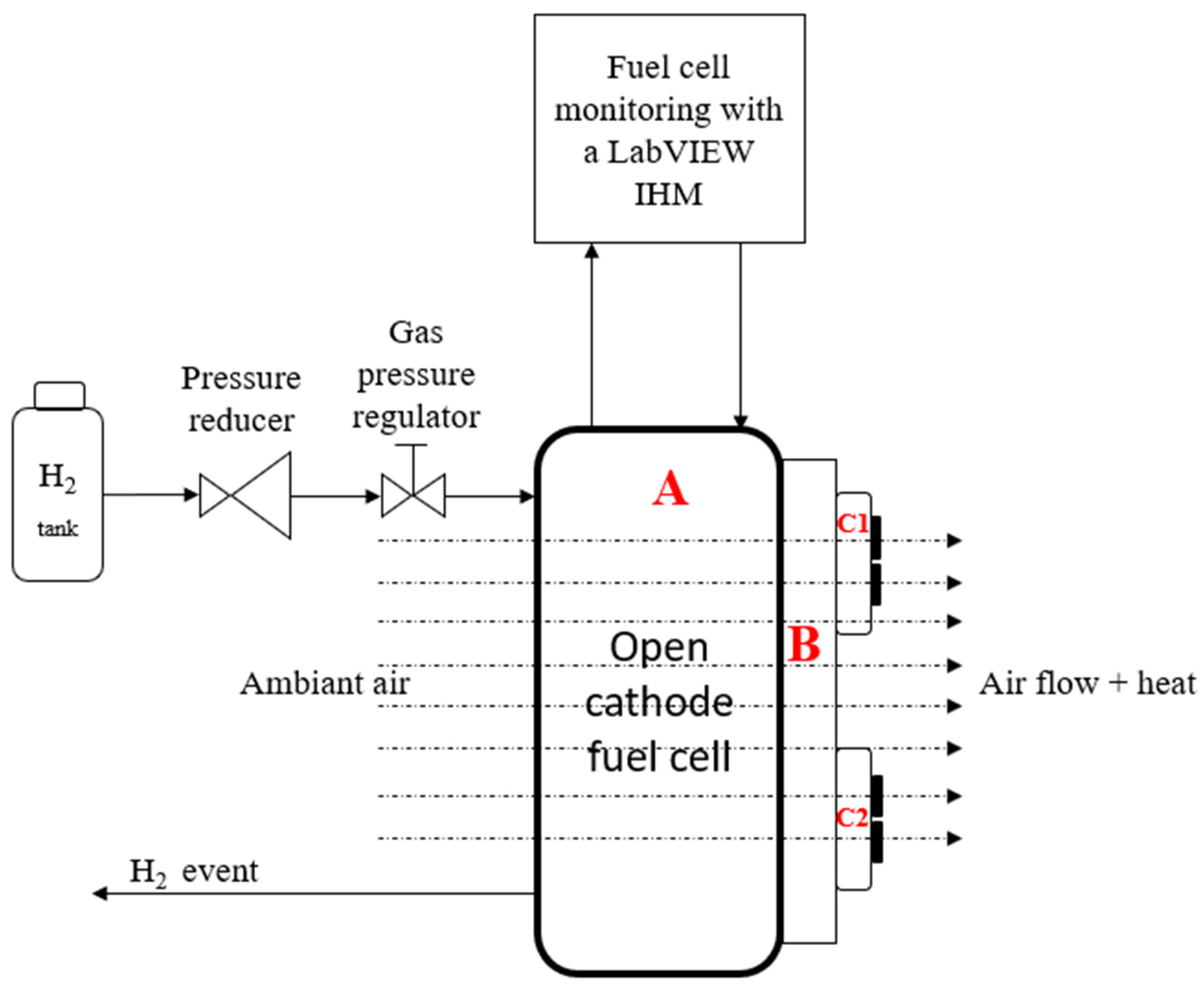
As presented in
Figure 1, the anode fuel cell is supplied with pure hydrogen from a tank. The cathode is fed by ambient air which is dragged into the fuel cell with two fans, C1 and C2, which are in the suction mode. Fans are also used to monitor the fuel cell temperature by controlling the input fan voltage. The test bench is then monitored by a LabVIEW Graphical User Interface (GUI) and a DAQ device which allows for changes in the fuel cell setting points and gathering all relevant variables for any developments. The used fuel cell is a stack of 13 cells. Each cell is a membrane electrode assembly (MEA) which has a surface of 100 cm². It is a Ballard Mark 1020 ACS [
19] fuel cell stack that allows a maximum power production of 77 amps and an optimal operating point of 65 amps.
3. Experimental Protocol for the Self-Clustering-Based Diagnosis
Since OPEMFCs are directly linked to the external environment, several kinds of unexpected events can appear during operations. For instance, as depicted in [
20], operating conditions such as the temperature or the air supply are major issues for fuel cell performance. For instance, the authors highlighted that heat management mainly depends on current density and the airflow that comes from the external environment. Therefore, the ambient air quality, humidity, and temperature directly influence the fuel cell operating conditions. In this section, the goal is therefore to use a generic diagnosis algorithm only applied to the fuel voltage by assuming that this variable contains all relevant information about the fuel cell state of health. The desired result is to show the ability of the GDA to extract information about the fuel cell operating condition without knowing in advance the evolution of the external fuel cell environment.
The proposed experimentations proceed to a brutal environmental modification on the fuel cell by partially blocking the cathode air supply. The experimentations are then carried out in two steps: first, characterizing the fuel cell behavior without cathode air obstruction; then, provoking a cathode air obstruction and observing the effects through the GDA diagnosis tool. The cathode obstruction consists of reducing the cathode-supplied surface from 200 cm² to 56.5 cm² and proceeding to the fuel cell characterization with GDA.
The experimental protocol for the normal operating condition characterization is given as follows:
Step 1: Normal operating conditions
- 1.
Set the OPEMFC at 16 amps operating point and let all parameters reach a steady state;
- 2.
Carry out the fuel cell voltage measurement at 1 kHz on a sliding window of 1 min;
- 3.
The sliding window should be refreshed as a first input, first output (FIFO) mode;
- 4.
Perform the voltage measurement for a minimum of 15 min under normal conditions.
Step 2: Fault F1
- 5.
Proceed to a first cathode obstruction for 25 min;
- 6.
Remove the obstruction and let the fuel cell operate under normal conditions for 85 min.
Step 3: Fault F2
- 7.
Proceed to a second cathode obstruction for 40 min;
- 8.
Remove the obstruction and let the fuel cell operate under normal conditions for 50 min.
Step 4: Fault F3
- 9.
Proceed to a third cathode obstruction for 40 min;
- 10.
Remove the obstruction and let the fuel cell operate under normal conditions.
End the test after 60 min.
Normal and Faulty Operating Mode Characterization by GDA under Steady-State Operation
The first protocol test was launched on the OPEMFC, and the operating conditions were measured to observe the steady state.
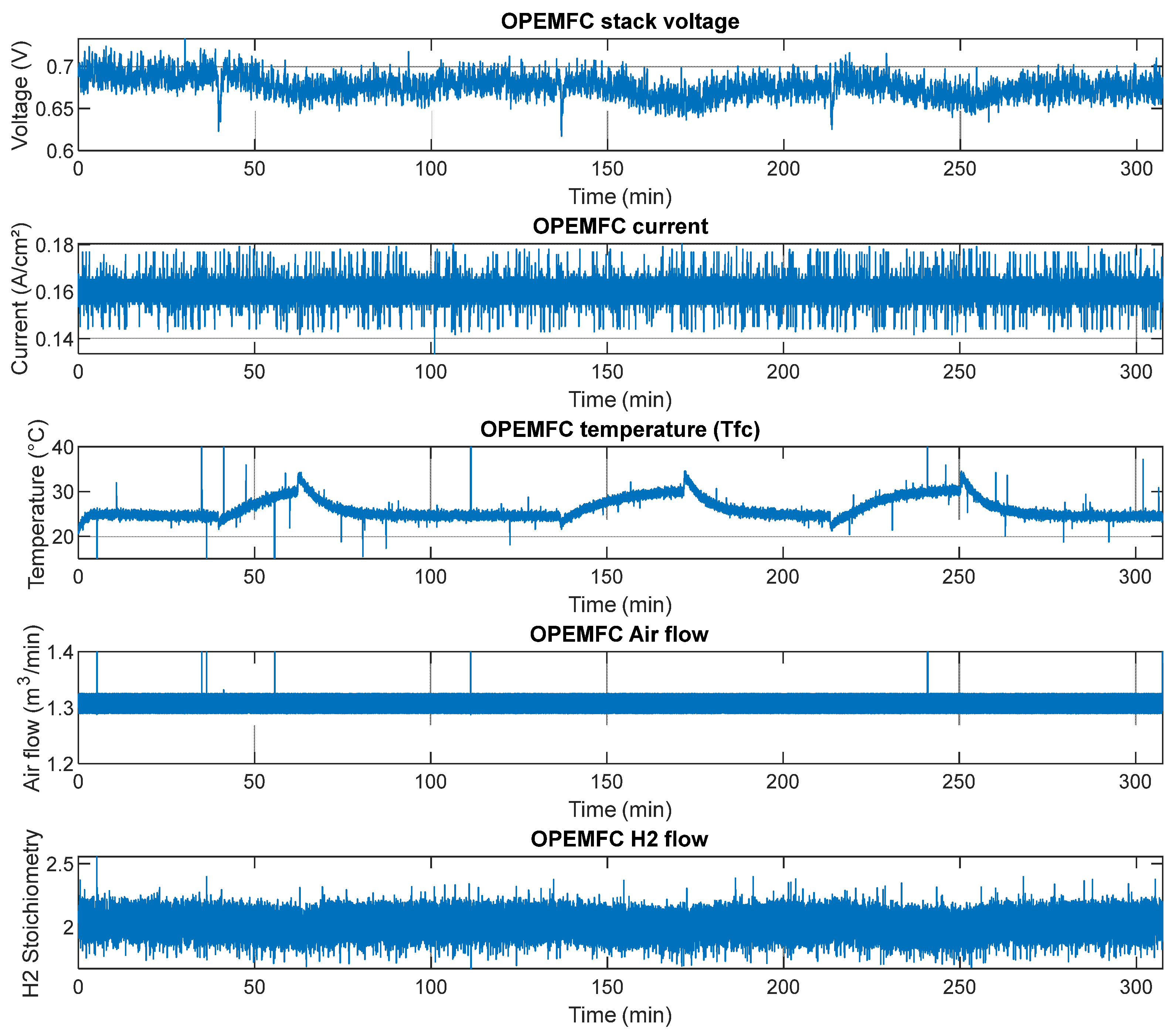
Figure 2 shows that the fuel cell is first set near 0.7 V for 0.16 A/cm². At this current density, the fuel cell temperature is stabilized at around 25 °C. Indeed, this operating point generates very low heat, and the fan speed has already reached its lowest set point value. Moreover, there is no heating system which is available which does not allow heating of the fuel cell. This setting corresponds to a plausible use case. However, when the fuel cell temperature setpoint is placed at higher values than the measured one, the temperature is not monitored under the setpoint and evolves in correlation with other quantities as plotted in
Figure 3. The airflow is sufficient to avoid any problem of cathode starvation or low stoichiometry issues. The hydrogen flow is set to a stoichiometry of 2.
Under the steady operating condition, a 1 kHz measurement of the fuel cell voltage is performed on a sliding window of 1 min. As explained in the first test protocol, the sliding window is updated as a first input, first output process.
The OPEMFC voltage measurement runs for 80 min. The GDA then scans the sliding window of 1 min, and the result is plotted in
Figure 3.
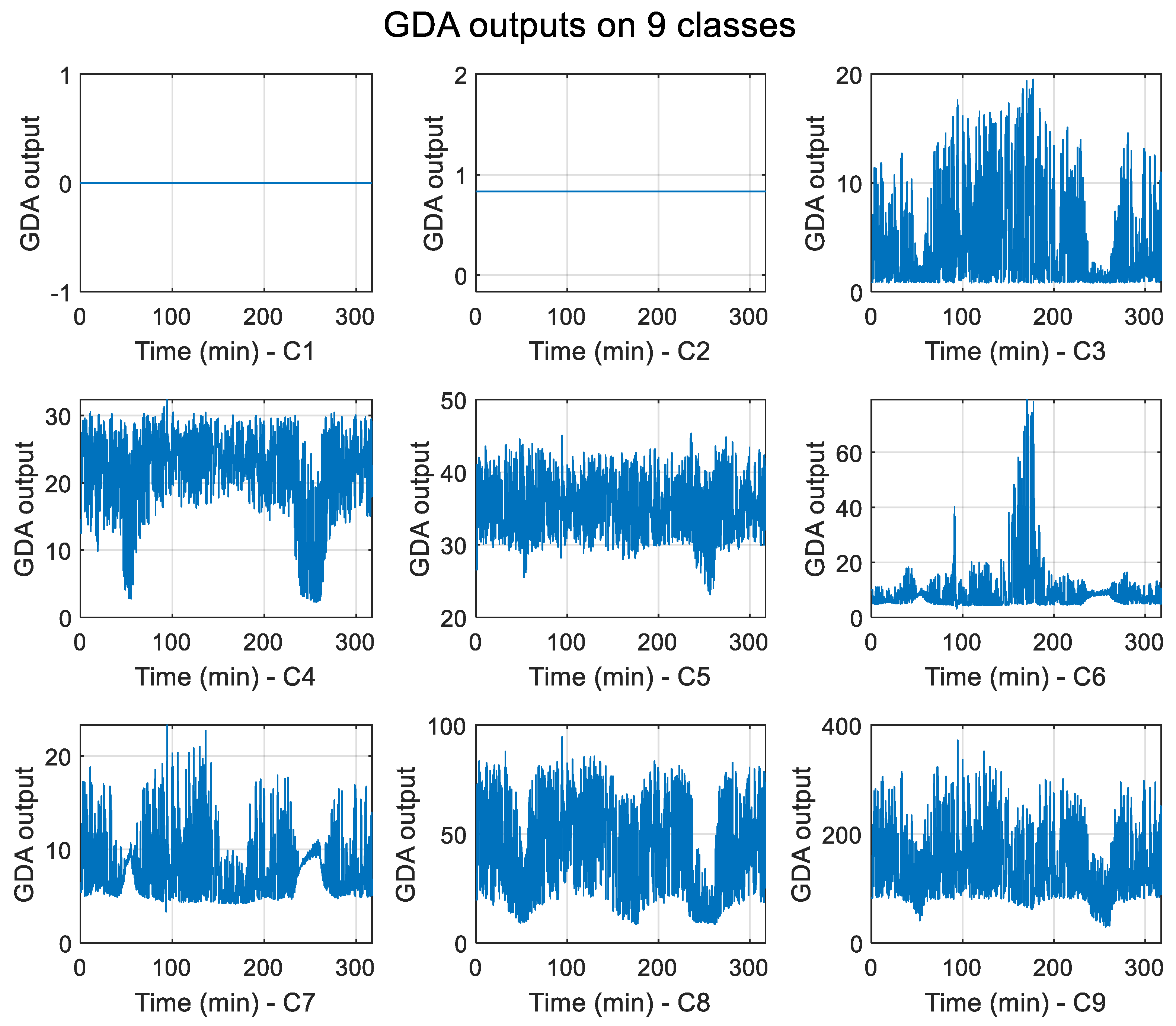
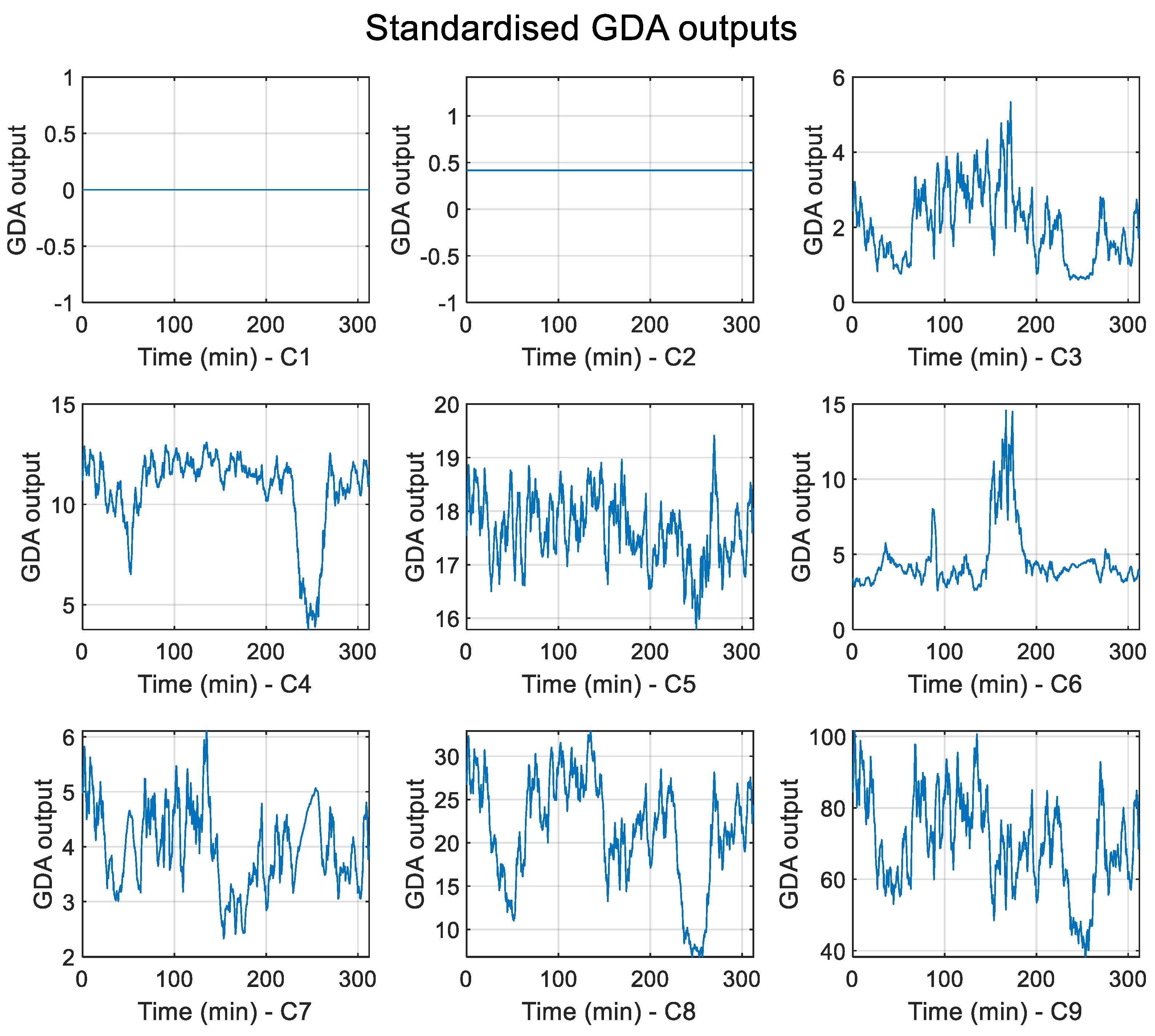
Figure 3 shows the decomposition by the GDA of the fuel cell voltage signal to nine classes. The GDA is applied on a 1 kHz 1 min fuel cell voltage measurement. The GDA leads to a nine-class representation of the measured window. As each class of the GDA shows the signal behavior at several levels,
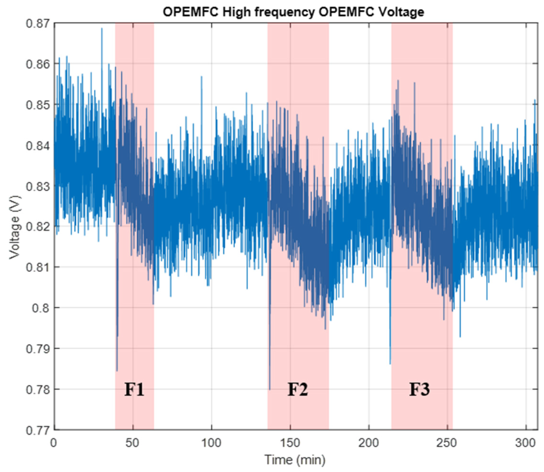
Figure 4 shows the contribution of each class in the signal to others. The goal is therefore to track the evolution of each class separately. In this way, when a fault occurs, the contribution of the fault to one or more classes is displayed.
The obstruction spans appear in
Figure 4, and the red areas F1 to F3 are the faulty areas.
The GDA is then launched on the overall test to detect fault obstruction occurrence. The algorithm uses a sliding window of 500 without overlapping and with data acquisition of 300 ms. The GDA outputs with the signal decomposition are represented in
Figure 5.
Each class is then integrated to extract each trend:
where the integration is set on a sliding window from
k to
N.
Ts is the sampling period, and
f is the GDA output.
The integration computation aims to track the signal behavior on the defined sliding window. The obtained signal is the system’s behavior history. The integration is plotted in
Figure 6.
Then,
Figure 6 shows several areas where
I has higher amplitudes. To isolate these amplitudes, each signal is normalized and derived as follows:
First, a Z-score normalization is performed:
where
M is the mean of the sliding window and
σ is the standard deviation:
where
n is the number of elements in the sliding window.
Then, a derivative is calculated:
Finally, to reduce low derivative values, an amplification of the
Sd of each class
k (
Sk) is performed to obtain
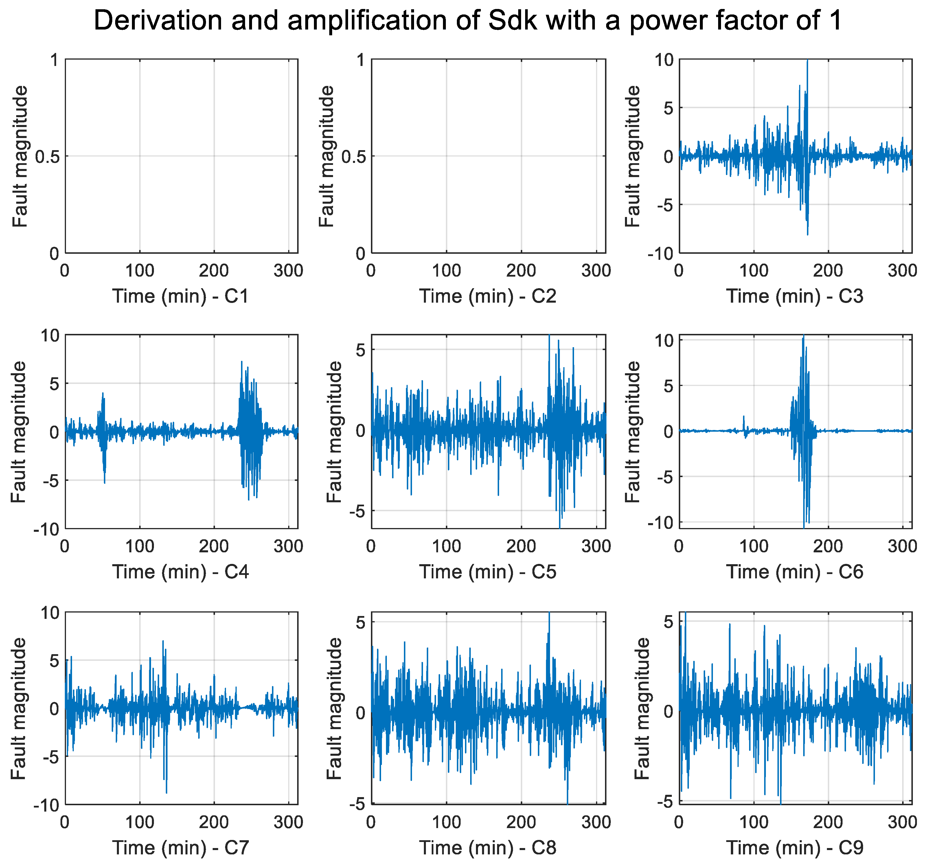
Sdk and avoid the trend. Then,
Sdk is amplified by the product of
Sk with
Sdk as follows:
Here, p is the power factor of the amplification.
These two operations provide the following
Figure 7 for an amplification factor of 1.
Then, a higher amplification factor gives a better result by reducing the noise, as shown in
Figure 8.
Finally, to obtain unique information for the diagnostic result, each amplified class is merged into a single vector.
Each class is then merged by the following process:
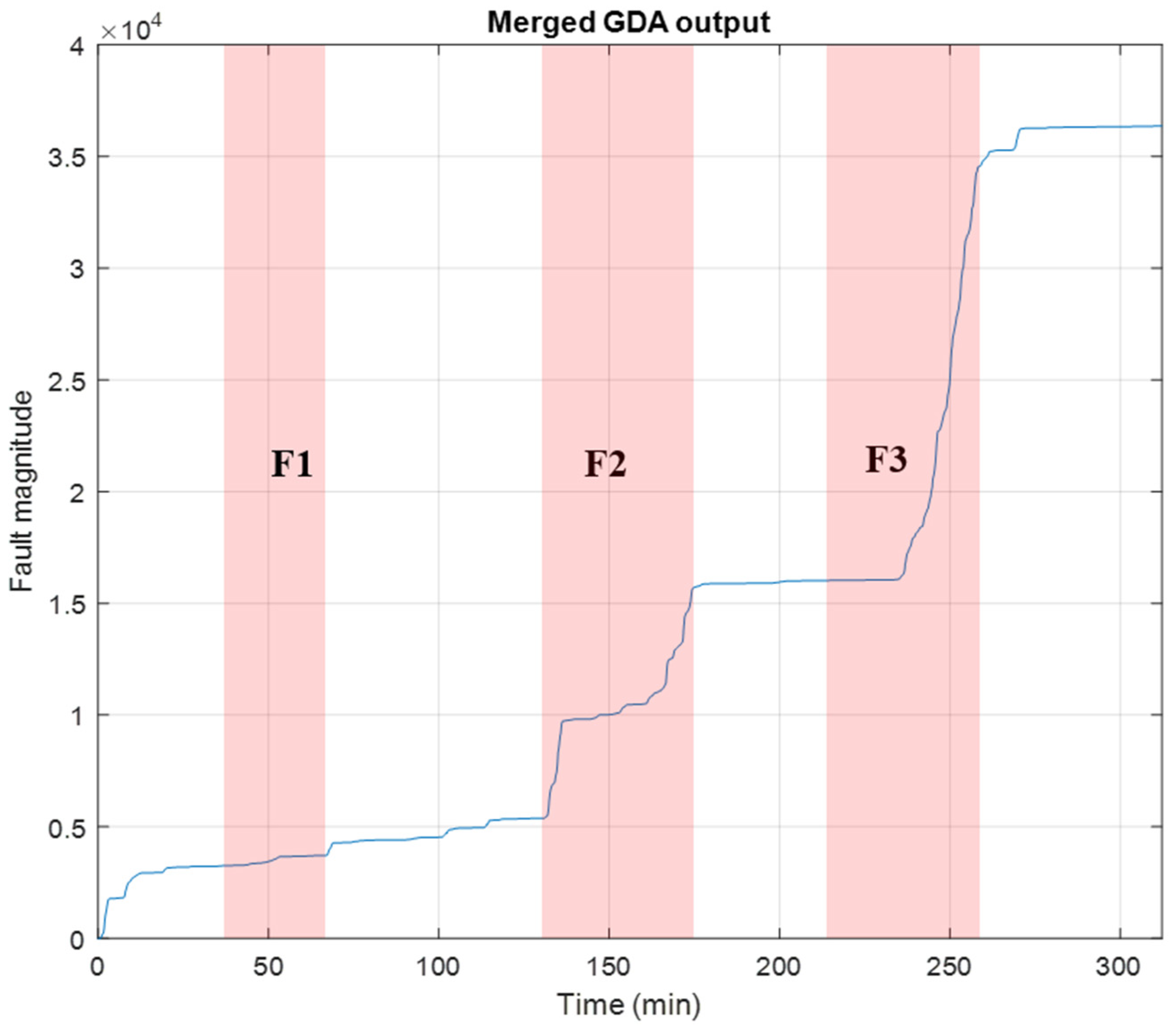
The merged GDA output, therefore, appears in the following
Figure 9.
Figure 9, therefore, shows red areas. F1 is the first fault generation process, F2 and F3 are the second and third fault generation processes, respectively. The blue line is the fault magnitude. Then, to allow the most suitable analysis of the merged outputs, a cumulative sum
Mc of
M is set:
That cumulative sum leads to the following
Figure 10.
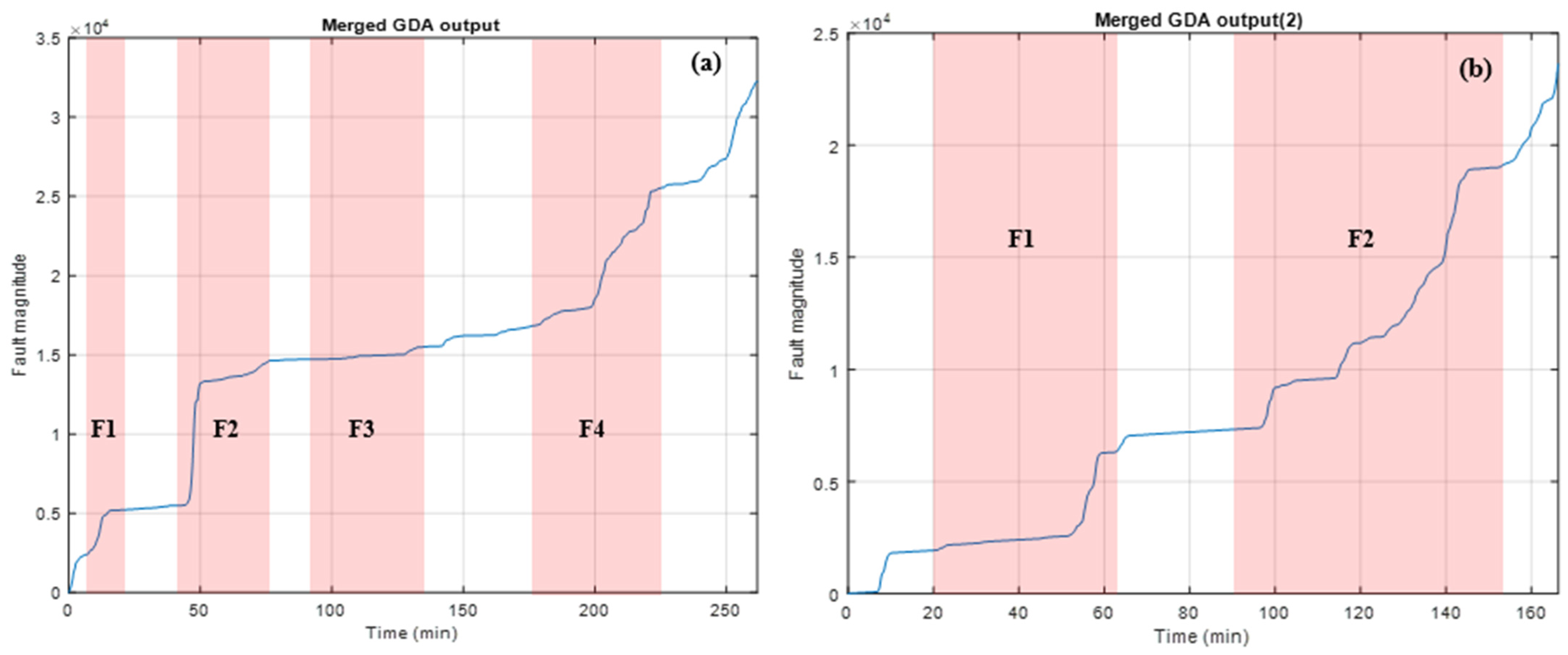
Figure 10 shows the cumulative sum of the GDA output. It appears that the slope has a significant progression under a faulty condition in the red areas. Besides red areas, slopes are very small, corresponding to a normal faulty operation.
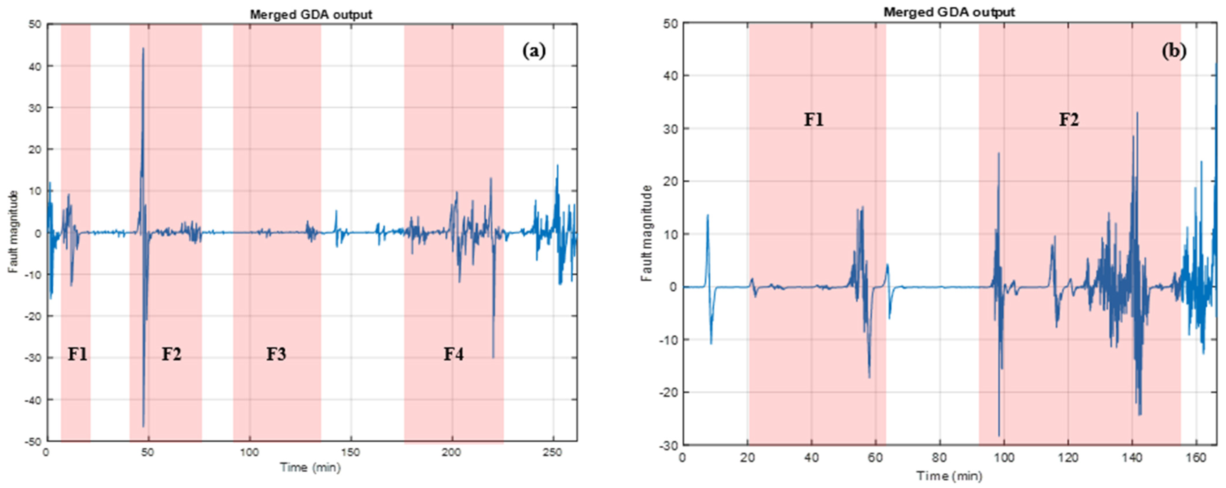
Then, the same data processing is applied to two new experiments of cathode obstruction. The results appear in
Figure 11 below.
As for the first experiment, the cumulative sum of the GDA outputs is set. The results are plotted below.
Figure 12 shows a significant progression of the slopes when a faulty condition occurred. At the end of experiments 2 and 3, it is, therefore, possible to observe a slope incrementation. The authors assume that the effect of the cathode obstruction also has an influence on the fuel cell even after the cathode obstruction removal.
The results thus show a good response to the GDA for the three experiments. The results are discussed in the next section.
4. Result Analysis and Discussion
The proposed fault diagnosis method aims to diagnose an OPEMFC fault condition by staying in the time-domain representation. Indeed, the GDA is used for an autonomous operation to classify a time-domain signal into several classes. It is the temporal evolution of each class that is the relevant information for the fuel cell state of health characterization.
The experimental results are gathered from the nine classes of the GDA output. The first abnormal experimental operating condition in
Figure 4 consists of the obstruction of the air input gas flow. In this way, the fuel cell voltage signal is decomposed by the GDA, and nine classes are created. After the first cathode obstruction, fault detection is observed and appears differently on classes. Regarding experiment 1, the fuel cell obstruction is set three times: first between 45 and 70 mn (I1), then between 135 and 180 mn (I2), and finally between 215 and 260 mn (I3). On the first interval I1, the fault can be observed on C8 and C9. For the second obstruction, the faulty condition can mostly be observed on C3, C6, C7, and C9. Regarding the last obstruction, the faulty operation mode has a major influence on C3, C4, C5, C8, and C9.
This information contained in the nine classes is then merged into a single graph as plotted in
Figure 10. After the cathode obstruction removal, the faulty condition is mitigated, and the slope has a low value. However, experiments 2 and 3 plotted in
Figure 12 show that after the last cathode obstruction, operation remains after the obstruction removal. Two possible reasons could be proposed for that phenomenon. First, the mitigation time is too short for efficient fault mitigation. The second possibility is a cumulative effect of cathode obstruction along the experiment that leads to a long-term fuel cell disruption.
The GDA efficiency can be highlighted with a suitable comparison with other tools available in the literature. For instance, in [
20], the authors proposed a SVM algorithm with diagnosis rules to diagnose a PEMFC’s state of health. The performance of their algorithm is summarized in
Table 1. Another more advanced tool called discrete hidden Markov model fault diagnosis based on k-means clustering in [
21] (DHMM-K) is also relevant for GDA efficiency comparison. As for SVM, the results appear in
Table 1. For that purpose, some metrics are defined as follows:
- -
Result accuracy;
- -
Complexity: number of signal transformations.
The DHMM-K algorithm needs three steps before clustering, also called key problems to be solved. First, a forward–backward algorithm is applied to the signal. Then, a Viterbi algorithm is used, and finally, it is the Baum–Welch algorithm that is used. After these steps, a K-means clustering is launched. The computation time is reduced compared to SVM because there is no training step.
The SVM method needs two steps. First, training is carried out, and then a performing step is realized.
GDA needs four steps. First, the signal is modified to amplify slopes. Then, several classes are created and merged to reduce the number of classes. Finally, each class becomes a new time series which is filtered to highlight changes in the system behavior. These algorithms are compared considering the following:
- -
Availability of the algorithm;
- -
Number of diagnosable states.
GDA has the fastest response time compared to DHMM-K and SVM. This can be explained by the smallest number of diagnosable states. However, in further work, it could be possible to extract other states through GDA and then compute the new computation time.
Finally, this paper proposed a novel self-clustering algorithm merged with the GDA approach for fuel cell fault detection. The major strength of the method lies in the filtering of the wrong measurement based on a sliding window integration. Therefore, a very low wrong fault diagnosis is possible. However, due to the amount of data used and the diagnosis setting chosen, some system behaviors could not be observable. For that reason, a suitable data window should be found for a more accurate analysis of the signal.
The diagnosis method does not provide fault identification. That issue remains under study.
