
Synthesis of ZnO Nanorods and Its Application in Zinc-Silver Secondary Batteries

Abstract
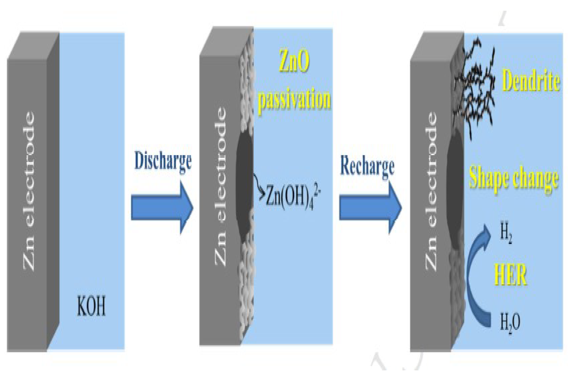
:1. Introduction
2. Materials and Methods
2.1. Preparation Materials
2.2. Characterization
2.3. Assessment of Prepared ZnO Nanoparticles for Electrochemical Testing
3. Results and Discussion
3.1. Factors Affecting Morphology and Surface Structure of ZnO Nanoparticles
3.1.1. SEM Image Analysis
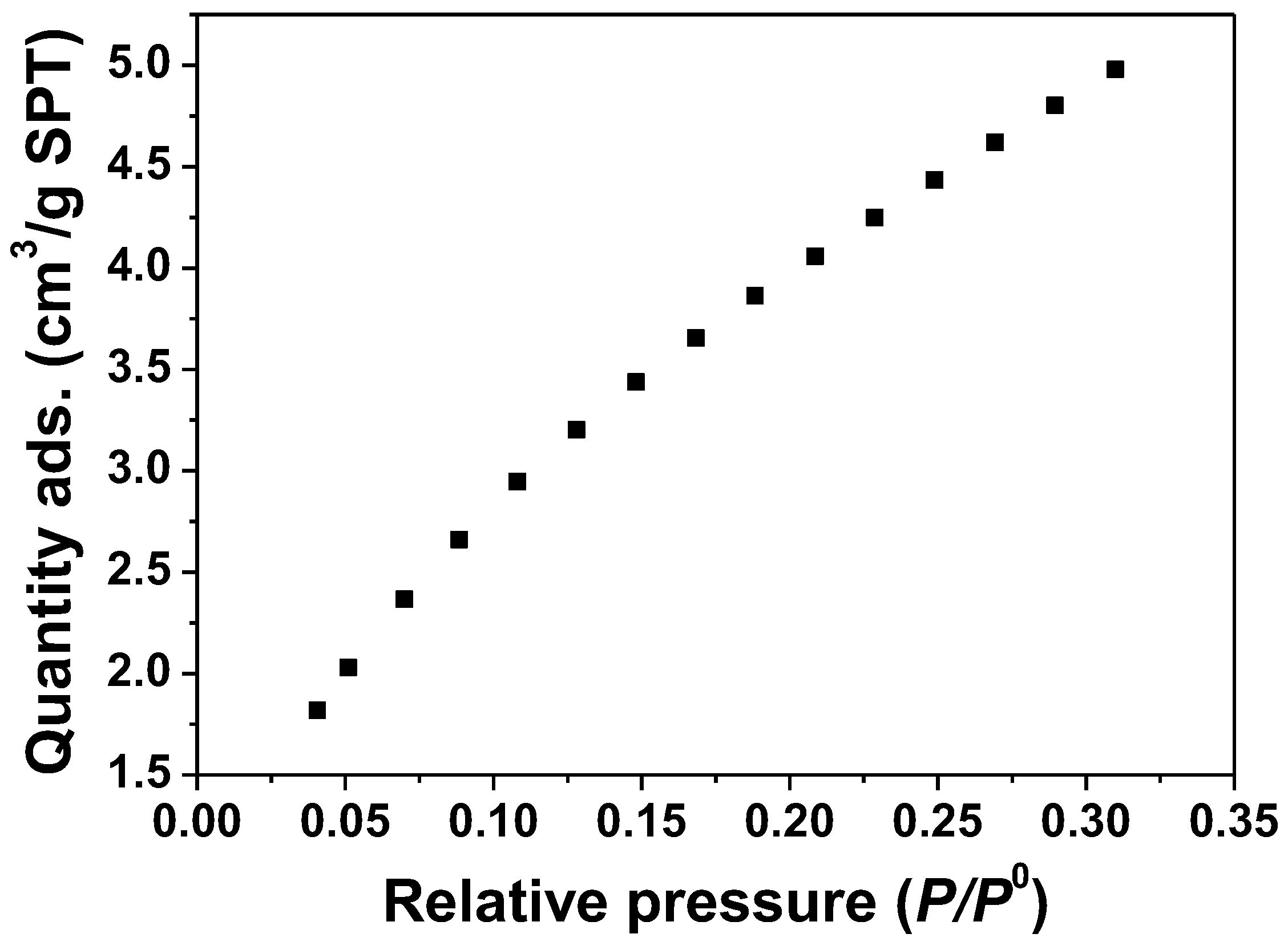
3.1.2. Determination of Surface Area by the BET Method
3.2. Structure and Morphology
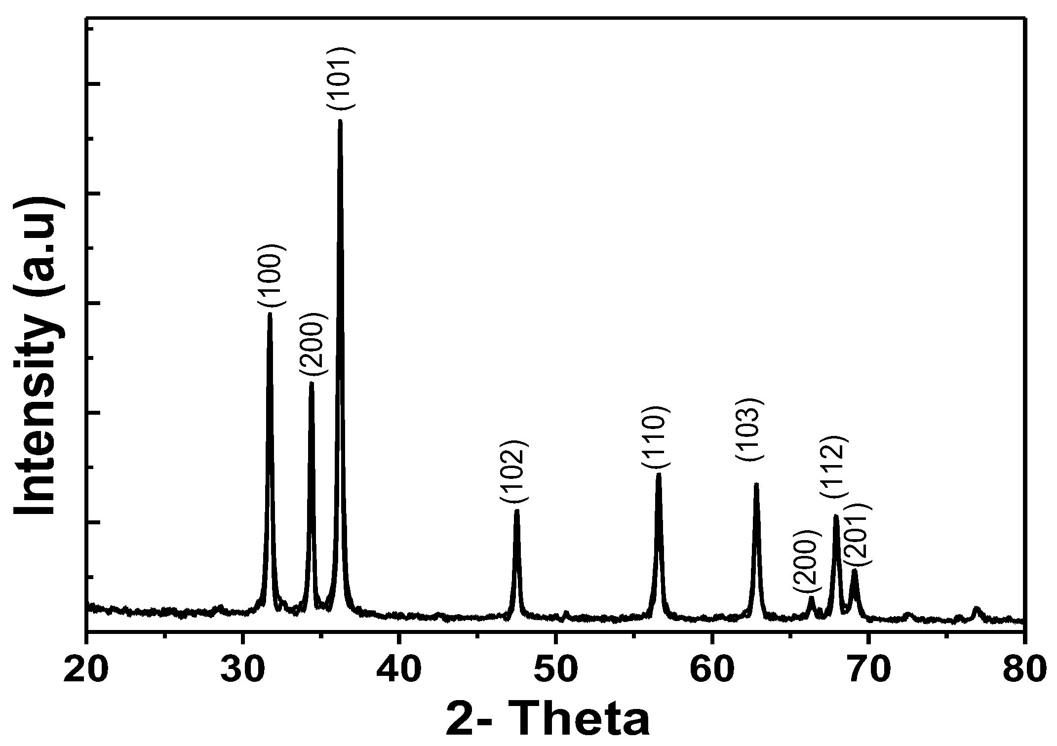
3.2.1. XRD Analysis
3.2.2. EDS Analysis
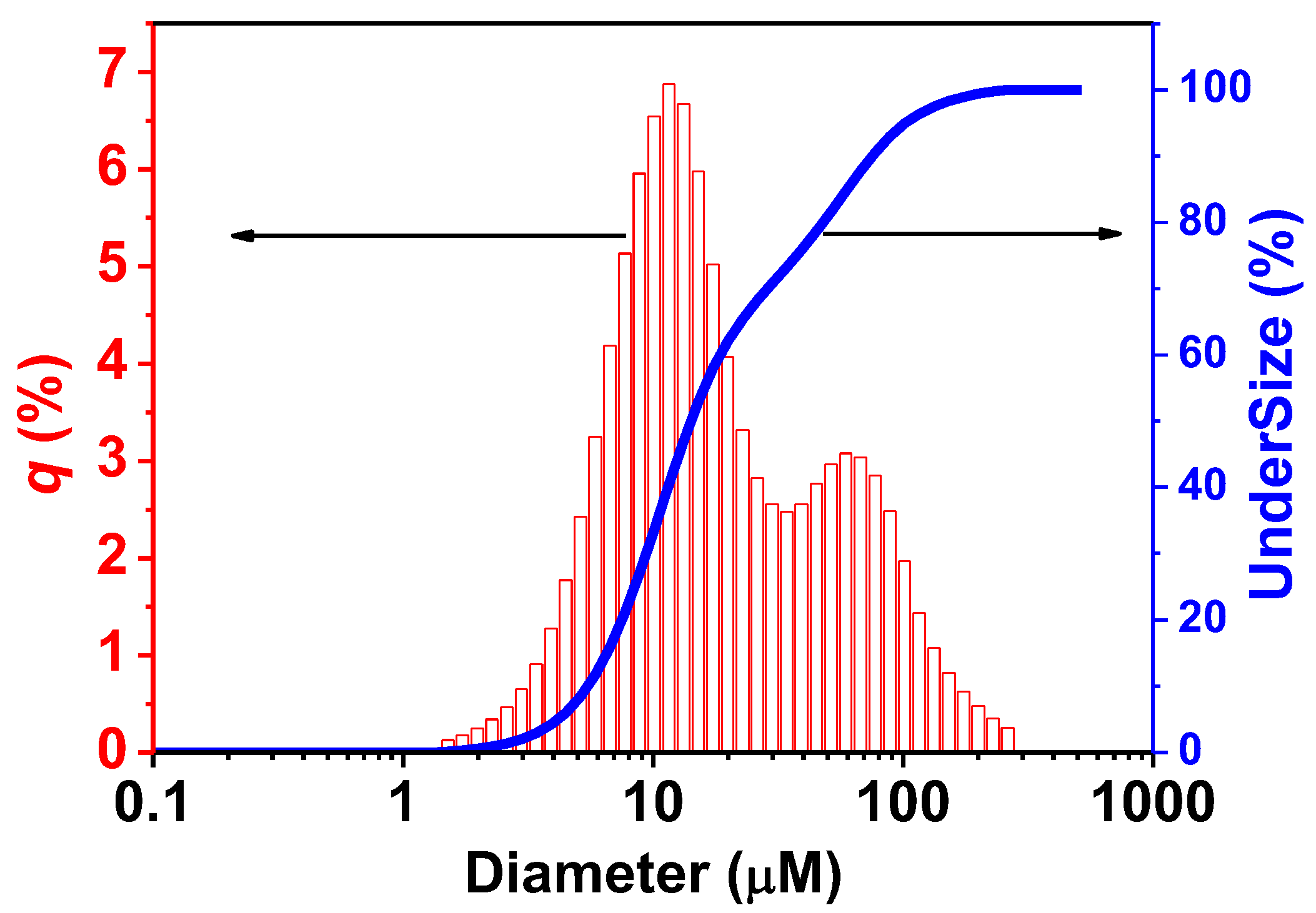
3.2.3. Particle-Size Distribution by Laser Diffraction
3.3. Electrochemical Testing
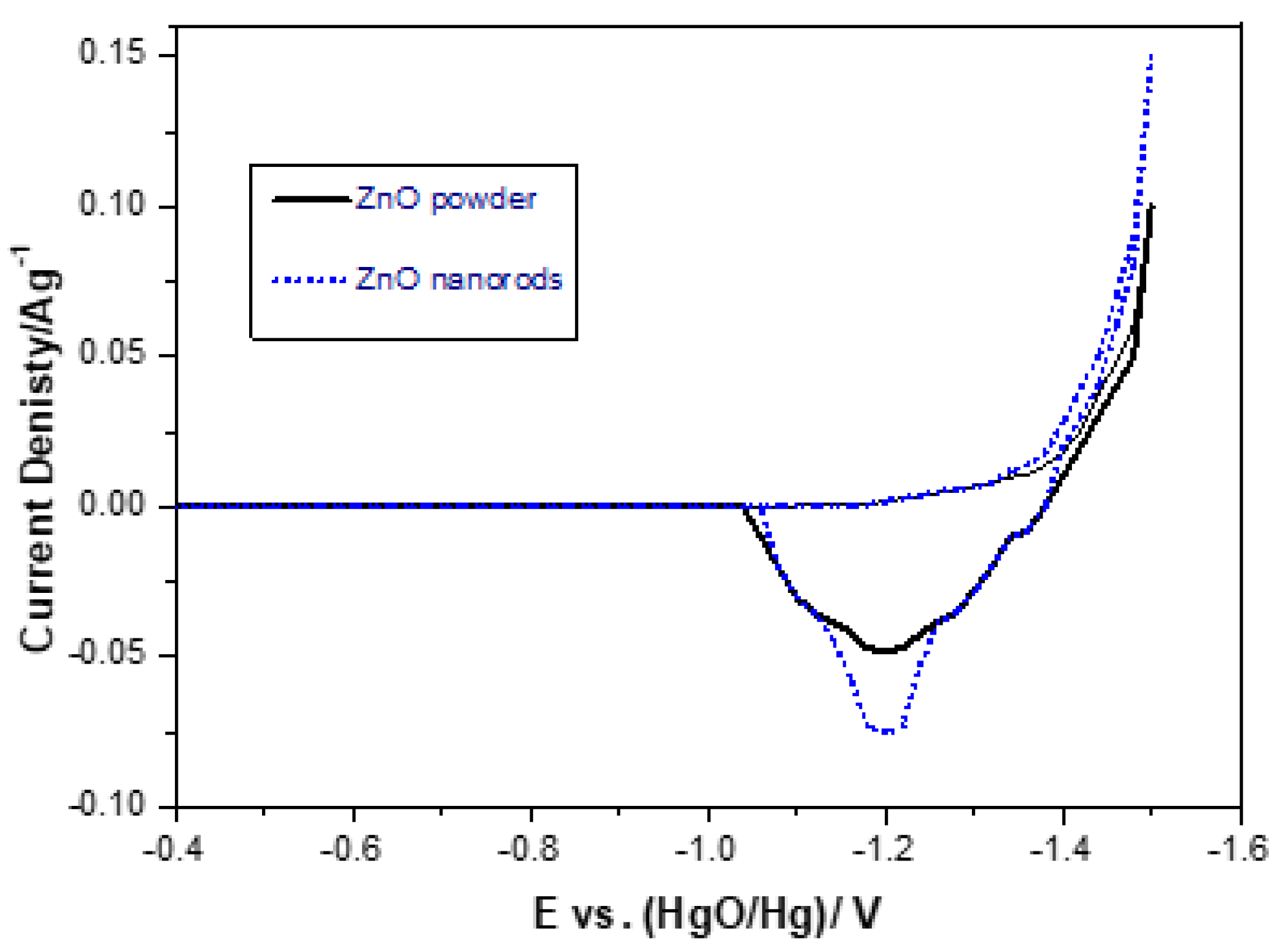
3.3.1. Cyclic Voltammetry (CV) Curves for Zinc Electrodes

| Samples | Ea(V) | Ec(V) | △Ea,c(V) |
|---|---|---|---|
| ZnO powder | −1.181 | −1.563 | 0.372 |
| ZnO nanorods | −1.186 | −1.546 | 0.340 |
3.3.2. Tafel Plots
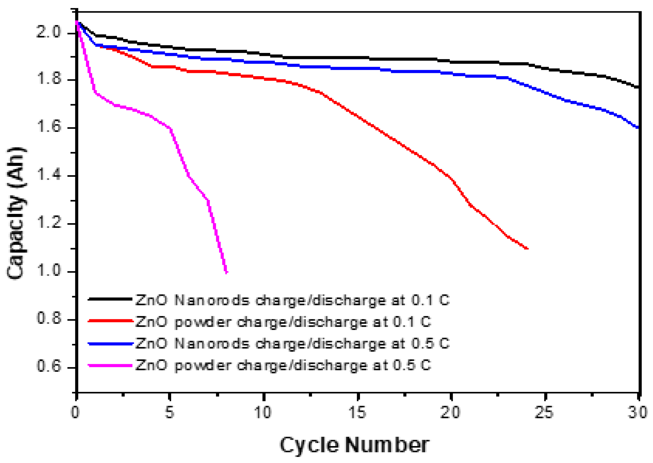
3.3.3. Properties of Charge/Discharge
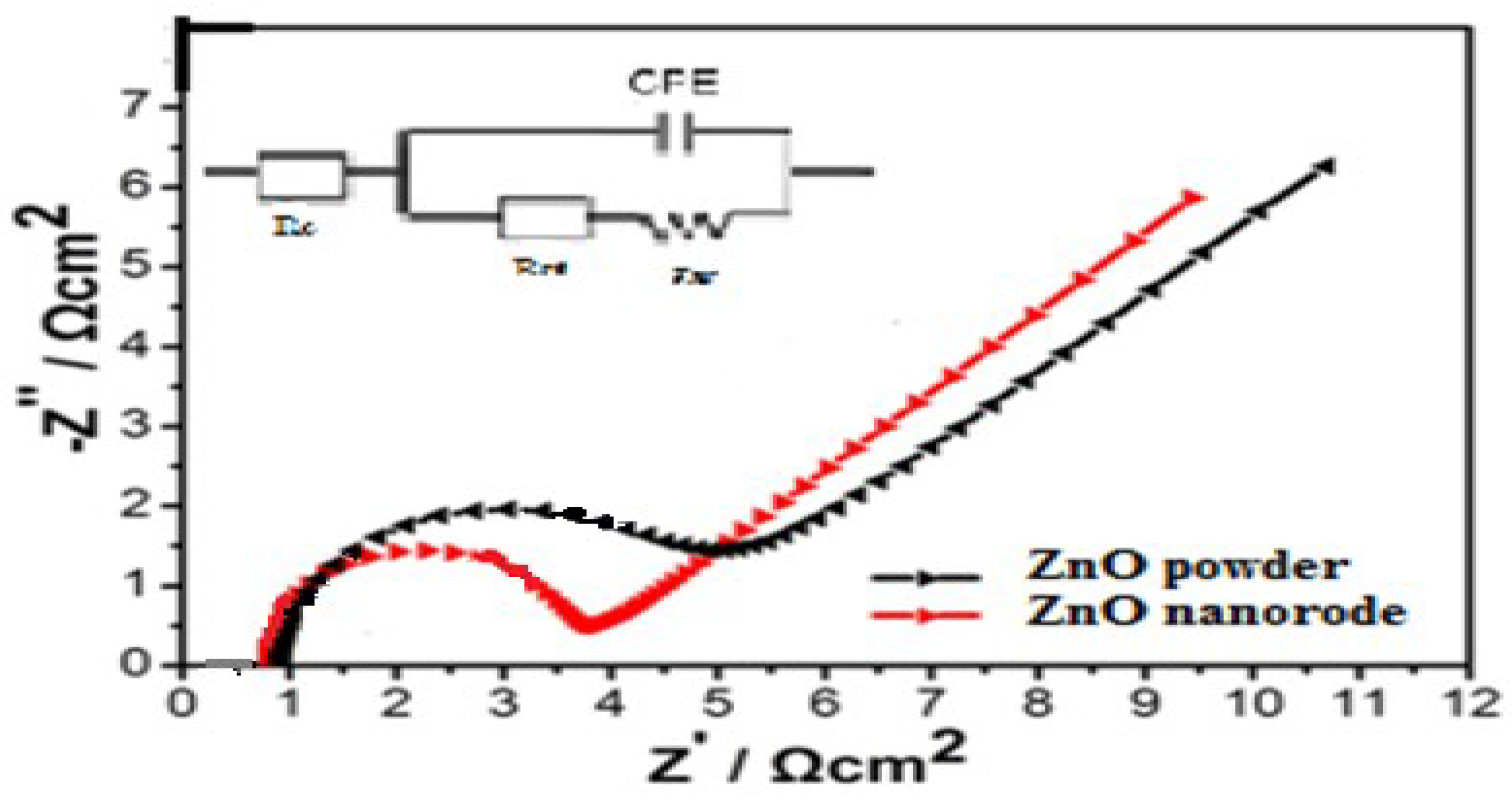
3.3.4. Electrochemical Impedance Spectroscopy (EIS)
4. Conclusions
Author Contributions
Funding
Institutional Review Board Statement
Informed Consent Statement
Data Availability Statement
Conflicts of Interest
References
- Mishra, Y.K.; Adelung, R. ZnO tetrapod materials for functional applications. Mater. Today 2018, 21, 632–651. [Google Scholar] [CrossRef]
- Moezzi, A.; McDonagh, A.M.; Cortie, M.B. ZnO particles: Synthesis, properties and applications. Chem. Eng. J. 2012, 185–186, 1–22. [Google Scholar] [CrossRef]
- Mashkoor, A.; Shi, Y.; Amjad, N.; Hongyu, S.; Wanci, S. Synthesis of hierarchical flower-like ZnO nanostructures and their functionalization by Au nanoparticles for improved photocatalytic and high performance Li-ion battery anodes. J. Mater. Chem. 2011, 21, 7723–7729. [Google Scholar]
- Jian-Hong, L.; Min-Hsiung, H.; Yi-Wen, C.; Ing Chi, L. The effect of TiO2 coating on the electrochemical performance of ZnO nanorod as the anode material for lithium-ion battery. Appl. Phys. A 2011, 102, 545–550. [Google Scholar]
- Wang, Z.L. ZnO nanostructures: Growth, properties and application. J. Phys. Condens. Matter 2004, 16, R829–R858. [Google Scholar] [CrossRef]
- Abdi, S.; Dorranian, D. Effect of CTAB concentration on the properties of ZnO nanoparticles produced by laser ablation method in CTAB solution. Opt. Laser Technol. 2018, 108, 372–377. [Google Scholar] [CrossRef]
- Huong, D.T.; Van Tu, N.; Dung, N.Q.; Nhuong, C.M.; Quyen, N.T.C.; Van Tan, L. Equilibrium, Kinetic and Thermodynamic Studies for Sorption of Phosphate from Aqueous Solution Using ZnO Nanoparticles. Processes 2020, 8, 1397. [Google Scholar]
- Dong, L.; Jiao, J.; Tuggle, D.W.; Petty, J.M.; Elliff, S.A.; Coulter, M. ZnO nanowires formed on tungsten substrates and their electron field emission properties. Appl. Phys. Lett. 2003, 82, 1096–1098. [Google Scholar] [CrossRef]
- Tian, Z.R.; Voigt, J.A.; Liu, J.; Mckenzie, B.; Mcdermott, M.J. Biomimetic Arrays of Oriented Helical ZnO Nanorods and Columns. J. Am. Chem. Soc. 2002, 124, 12954–12955. [Google Scholar] [CrossRef]
- Ge, C.; Xie, C.; Hu, M.; Gui, Y.; Bai, Z.; Zeng, D. Structural characteristics and UV-light enhanced gas sensitivity of La-doped ZnO nanoparticles. Mater. Sci. Eng B 2007, 141, 43–48. [Google Scholar] [CrossRef]
- Zhang, H.; Yang, D.; Li, S.; Ma, X.; Ji, Y.; Xu, J.; Que, D. Controllable growth of ZnO nanostructures by citric acid assisted hydrothermal process. Mater. Lett. 2005, 59, 1696–1700. [Google Scholar] [CrossRef]
- Ji, Y.; Wei, B.; Wang, L.; Zhang, Y.-F. Electrical characterization of ZnO nanowires contacted to tungsten electrodes. J. Beijing Univ. Technol. 2009, 35, 1235–1240. [Google Scholar]
- Boeckler, C.; Feldhoff, A.; Oekermann, T. Electrodeposited ZnO/Phthalocyanine Films—An Inorganic/Organic Hybrid System with Highly Variable Composition. Adv. Funct. Mater. 2007, 17, 3864–3869. [Google Scholar] [CrossRef]
- Quartarone, E.; Dall Asta, V.; Resmini, A.; Tealdi, C.; Tredici, I.G.; Tamburini, U.A.; Mustarelli, P. Graphite-coated ZnO nanosheets as high-capacity, highly stable, and binder-free anodes for lithium-ion batteries. J. Power Sources 2016, 320, 314–321. [Google Scholar] [CrossRef]
- Ni, Y.-H.; Wei, X.-W.; Ma, X.; Hong, J.-M. CTAB assisted one-pot hydrothermal synthesis of columnar hexagonal-shaped ZnO crystals. J. Cryst. Growth 2005, 283, 48–56. [Google Scholar] [CrossRef]
- Jian, S.; Tian, Z.; Hu, J.; Zhang, K.; Zhang, L.; Duan, G.; Yang, W.; Jiang, S. Enhanced visible light photocatalytic efficiency of La-doped ZnO nanofibers via electrospinning-calcination technology. Adv. Powder Mater. 2022, 1, 100004. [Google Scholar] [CrossRef]
- Huang, L.Y.; Wang, X.; Yin, F.X.; Zhang, Y.G.; Gao, J.W.; Liu, J.M.; Zhou, G.F.; Bakenov, Z. ZnO nanorods grown directly oncopper foil substrate as a binder-free anode for high performance lithium-ion batteries. Int. J. Electrochem. Sci. 2016, 11, 8439–8446. [Google Scholar] [CrossRef]
- Linden, D.; Reddy, T.B. Handbook of Batteries, 3rd ed.; McGraw-Hill: New York, NY, USA, 2002; pp. 1–16. [Google Scholar]
- Jinping, L.; Yuanyuan, L.; Ruimin, D.; Jian, J.; Yingying, H. Carbon/ZnO Nanorod Array Electrode with Significantly Improved Lithium Storage Capability. J. Phys. Chem. C 2009, 113, 5336–5339. [Google Scholar]
- Guo, R.; Yue, W.; An, Y.; Ren, Y.; Yan, X. Graphene-encapsulated porous carbon-ZnO composites as high-performance anode materials for Li-ion batteries. Electrochim. Acta 2014, 135, 161–167. [Google Scholar] [CrossRef]
- Li, L.; Pan, S.; Dou, X.; Zhu, Y.; Huang, X.; Yang, Y.; Li, G.; Zhang, L. Direct Electrodeposition of ZnO Nanotube Arrays in Anodic Alumina Membranes. J. Phys. Chem. C 2007, 111, 7288–7291. [Google Scholar] [CrossRef]
- Ullah, S.; Badshah, A.; Ahmed, F.; Raza, R. Electrodeposited Zinc Electrodes for High Current Zn/AgO Bipolar Batteries. Int. J. Electrochem. Sci. 2011, 6, 3801–3811. [Google Scholar]
- Wu, Z.S.; Zhou, G.M.; Yin, L.C.; Ren, W.R.; Li, F.; Cheng, H.M. Graphene/metal oxide composite electrode materials for energy storage. Nano Energy 2012, 1, 107–131. [Google Scholar] [CrossRef]
- Yuan, G.; Wang, G.; Wang, B.J. Synthesis and electrochemical investigation of radial ZnO microparticles as anode materials for lithium-ion batteries. Ionics 2015, 21, 365–371. [Google Scholar] [CrossRef]
- Wang, L.; Yang, Z.; Chen, X.; Qin, H.; Yan, P. Formation of porous ZnO microspheres and its application as anode material with superior cycle stability in zinc-nickel secondary batteries. J. Power Sources 2018, 396, 615–620. [Google Scholar] [CrossRef]
- Karpinski, A.P.; Makovetski, B.; Russel, S.J.; Serenyi, J.R.; Williams, D.C. Silver- Zinc: Status of Technology and Applications. J. Power Sources 1999, 80, 53–60. [Google Scholar] [CrossRef]
- Hsieh, C.T.; Lin, C.Y.; Chen, Y.F.; Lin, J.S. Synthesis of ZnO@graphene composites as anode materials for lithium-ion batteries. Electrochim. Acta 2013, 111, 359–365. [Google Scholar] [CrossRef]
- Braam, K.T.; Volkman, S.K.; Subramanian, V. Characterization and Optimization of printed, primary zinc-silver battery. J. Power Sources 2012, 199, 367–372. [Google Scholar] [CrossRef]
- Li, S.; Xiao, Y.; Wang, X.; Cao, M. A ZnO–graphene hybrid with remarkably enhanced lithium storage capability. Phys. Chem. Chem. Phys. 2014, 16, 25846–25853. [Google Scholar] [CrossRef]
- Zhang, H.; Zhu, L.; Li, W.; Liu, H. Effect of Y(OH)3 microparticles on the electrochemical performance of alkaline zinc electrodes. J. Rare Earth 2009, 27, 980–985. [Google Scholar] [CrossRef]
- Salkind, A.J.; McLarnon, F.; Sergeevich, V.; Bagotzky, V.S. Proceeding of the Symposium on Rechargeable Zinc Batteries. Electrochem. Soc. Proced. 1996, 95, 101. [Google Scholar]
- Lewis, H.; Jackson, P.; Salkind, A.; Danko, T.; Bell, R. Advanced membranes for alkaline primary and rechargeable alkaline cells with zinc anodes. J. Power Sources 2001, 96, 128–132. [Google Scholar] [CrossRef]
- Shivkumar, R.; Paruthimal, G.; Kalaignan Vasudevan, T. Effect of additives on zinc electrodes in alkaline battery systems. J. Power Sources 1995, 55, 53–62. [Google Scholar] [CrossRef]
- Smith, D.F.; Gucinsk, I.J. Synthetic silver oxide and mercury free zinc electrodes for zinc-silver reserve batteries. J. Power Sources 1999, 80, 66–71. [Google Scholar] [CrossRef]
- Shivkumar, R.; Paruthimal, G.K.; Vasudevan, T. Studies with porous zinc electrodes with additives for secondary alkaline batteries. J. Power Sources 1998, 75, 90–100. [Google Scholar] [CrossRef]
- Zhu, L.; Zhang, H.; Li, W.; Liu, H. New modification procedure of zinc powder in neodymium nitrate solution for improving the electrochemical performance of alkaline zinc electrodes. J. Phys. Chem. Solids 2009, 70, 45–54. [Google Scholar] [CrossRef]
- Mainar, A.R.; Iruin, E.; Bl’azquez, J.A. High performance secondary zinc-air/silver hybrid battery. J. Energy Storage 2021, 33, 102103. [Google Scholar] [CrossRef]
- Lyu, L.; Gao, Y.; Wang, Y.; Xiao, L.; Lu, J.; Zhuang, L. Improving the cycling performance of silver-zinc battery by introducing PEG-200 as electrolyte additive. Chem. Phys. Lett. 2019, 723, 102–110. [Google Scholar] [CrossRef]
- Shang, W.; Yu, W.; Liu, Y.; Li, R.; Dai, Y.; Cheng, C.; Tan, P.; Ni, M. Rechargeable alkaline zinc batteries: Progress and challenges. Energy Storage Mater. 2020, 31, 44–57. [Google Scholar] [CrossRef]
- Bharatiya, D.; Parhi, B.; Swain, S.K. Characterization and dielectric properties of GO based ZnO embedded mixed metal oxides ternary nanostructured composites. J. Alloys Compd. 2021, 869, 159274. [Google Scholar] [CrossRef]
- Zhao, Z.; Liu, B.; Shen, Y.; Wu, T.; Zang, X.; Zhao, Y.; Zhong, C.; Ma, F.; Hu, W. Comparative study of intrinsically safe zinc-nickel batteries and lead-acid batteries for energy storage. J. Power Sources 2021, 510, 230393. [Google Scholar] [CrossRef]
- Mojtahedi, M.; Goodarzi, M.; Sharifi, B.; Khaki, J.V. Effect of electrolysis condition of zinc powder production on zinc–silver oxide battery operation. Energy Convers. Manag. 2011, 52, 1876–1880. [Google Scholar] [CrossRef]
- Jeong, J.; Lee, J.-W.; Shin, H.-C. Unique electrochemical behavior of a silver–zinc secondary battery at high rates and low temperatures. Electrochim. Acta 2021, 396, 139256. [Google Scholar] [CrossRef]
- Le, S.; Zhang, L.; Song, X.; He, S.; Yuan, Z.; Liu, F.; Zhang, N.; Sun, K.; Feng, Y. Review-status of zinc-silver battery. J. Electrochem. Soc. 2019, 166, A2980–A2989. [Google Scholar] [CrossRef]
- Wang, Y.; Luo, J.; Zhou, L.; Lu, X. Highly reversible anode with Bi and ZnO dual chemistry for aqueous alkaline battery. J. Power Sources 2022, 554, 231903. [Google Scholar] [CrossRef]
- Liu, X.; Wang, Q.; Hu, W. Facile synthesis of uniformly coated ZnO@Bi2O3 composites anode for long-cycle-life zinc–nickel battery. J. Energy Storage 2022, 58, 106350. [Google Scholar] [CrossRef]
- Yuan, L.; Cai, J.; Wang, J. In situ growth of ZnO nanosheets on Ti3C2Tx MXene for Superior-Performance Zinc-Nickel secondary battery. Chem. Eng. J. 2023, 451, 19073. [Google Scholar] [CrossRef]


| Element | Theory | Result |
|---|---|---|
| Zn | 80.34 | 80.32 |
| O | 19.66 | 19.67 |
| Total | 100.00 | 99.99 |
| Samples | ECorr(V) | Jcorr(mA.cm−2) |
|---|---|---|
| ZnO powder | −1.4265 | 4.95 × 10⁻² |
| ZnO nanorods | −1.4180 | 3.86 × 10⁻² |
| Samples | Re/Ω | Rf/Ω | Rct/Ω |
|---|---|---|---|
| ZnO powder | 10.55 | 120.86 | 265.60 |
| ZnO nanorods | 9.45 | 60.81 | 98.78 |
Disclaimer/Publisher’s Note: The statements, opinions and data contained in all publications are solely those of the individual author(s) and contributor(s) and not of MDPI and/or the editor(s). MDPI and/or the editor(s) disclaim responsibility for any injury to people or property resulting from any ideas, methods, instructions or products referred to in the content. |
© 2023 by the authors. Licensee MDPI, Basel, Switzerland. This article is an open access article distributed under the terms and conditions of the Creative Commons Attribution (CC BY) license (https://creativecommons.org/licenses/by/4.0/).
Share and Cite
Nguyen, V.T.; Nguyen, H.T.; Tran, N.H. Synthesis of ZnO Nanorods and Its Application in Zinc-Silver Secondary Batteries. Electrochem 2023, 4, 70-83. https://doi.org/10.3390/electrochem4010008
Nguyen VT, Nguyen HT, Tran NH. Synthesis of ZnO Nanorods and Its Application in Zinc-Silver Secondary Batteries. Electrochem. 2023; 4(1):70-83. https://doi.org/10.3390/electrochem4010008
Chicago/Turabian StyleNguyen, Van Tu, Hung Tran Nguyen, and Nu Huong Tran. 2023. "Synthesis of ZnO Nanorods and Its Application in Zinc-Silver Secondary Batteries" Electrochem 4, no. 1: 70-83. https://doi.org/10.3390/electrochem4010008
APA StyleNguyen, V. T., Nguyen, H. T., & Tran, N. H. (2023). Synthesis of ZnO Nanorods and Its Application in Zinc-Silver Secondary Batteries. Electrochem, 4(1), 70-83. https://doi.org/10.3390/electrochem4010008