Article

Battery Energy Consumption Analysis of Automated Vehicles Based on MPC Trajectory Tracking Control

1
School of Information Science and Electrical Engineering, Shandong Jiaotong University, Jinan 250357, China
2
School of Control Science and Engineering, Shandong University, Jinan 250061, China
3
State Key Laboratory of Automotive Simulation and Control, Jilin University, Changchun 130022, China
*
Authors to whom correspondence should be addressed.
Electrochem 2022, 3(3), 337-346; https://doi.org/10.3390/electrochem3030023
Submission received: 13 May 2022 / Revised: 17 June 2022 / Accepted: 24 June 2022 / Published: 28 June 2022

Abstract

:
In the field of automated technology research and development, trajectory tracking plays a crucial role in the energy consumption of the vehicle’s power battery. Reducing the deviation between the actual trajectory and the reference trajectory is the focus of trajectory tracking research. This paper proposes the use of the model predictive control (MPC) method to reduce the deviation of lateral and longitudinal position between the actual driving trajectory and the reference trajectory. First, the driving conditions of the vehicle are reflected by establishing the vehicle dynamics model. Then, the MPC trajectory tracking controller is built by designing the objective function with constraints; Finally, the feasibility of this approach was verified by a joint Carsim-Simulink simulation. The simulation results show that the MPC controller designed in this paper can track the trajectory better, and reduce the lateral and longitudinal position deviation. To a certain extent, the battery energy consumption is reduced and the accuracy of the tracking trajectory and the safety of vehicle driving are improved.

1. Introduction

In recent years, power batteries have become more and more widely used in the field of automated vehicles. For the study of electric vehicles and automated vehicles, the service life and cruising range of batteries are the most urgent problems to be solved at present. By building a prediction model, predicting the cruising range of electric vehicles and calculating the power consumption required by various equipment, and using the transient simulation model to calculate the degree of influence of external factors during the driving of the vehicle, so as to relieve the driver’s cruising range anxiety [1]. One can design a dedicated control system to increase the range of electric vehicles and automated vehicles by extending the discharge time of the battery [2]. Part of the aging in the battery pack determines the performance of the entire battery pack, using distributed feasibility methods to detect the maximum range of balance current, and then predicting the battery life through model prediction [3]. In order to reduce the space occupied by the battery, a long cylindrical lithium battery can be used. Compared with the traditional battery, this long cylindrical battery has better heat dissipation capacity and longer cruising range [4,5]. Leverage machine learning methods can be used to simulate battery consumption and reduce uncertainty in the forecasting process. This approach gives the driver a more complete grasp of the battery pack’s performance, reducing range anxiety [6]. One can design an electric vehicle model, and calculate the average energy consumption per kilometer and the remaining cruising range of the vehicle through the prediction of various indicators of the battery pack [7]. At different operating temperatures, an insulating material and a heater are designed to reduce the heat loss of the battery in the environment by analyzing the performance of the battery pack [8,9]. In an EV’s battery management module, accurate prediction of battery state of charge and usage can improve battery life and cruising range [10]. The above methods are all improvements to the power battery. For unmanned vehicles, the vehicle will be affected by many uncertain factors, and the energy consumption of the power battery cannot be guaranteed. At this time, the high-efficiency and precise tracking trajectory can exert the maximum performance of the power battery.
In the trajectory tracking control method of automated vehicles, the commonly used control theories include PID control, fuzzy control, sliding mode control, model predictive control, and others. PID control, fuzzy control, and sliding mode control are widely used. In vehicle trajectory tracking control, combining PID control with the genetic algorithm as well as designing a fuzzy controller based on interval type-3 can improve the stability of lateral control for vehicles [11,12]. The trajectory tracking accuracy can be improved by optimizing the controller parameters and adding data-driven control [13,14]. PID-based DDPG control method and fuzzy control combined with the MPC method can improve the tracking stability and comfort of the vehicle under different operating conditions [15,16]. Adding visual search to fuzzy control makes steering more accurate [17]. Improved hybrid fuzzy controller for active vehicle suspension system optimizes vehicle ride smoothness and road holding [18]. The backstep sliding mode control can overcome the external interference, and the use of feedforward and backward combined with synovial control can effectively improve the vehicle tracking performance [19]. The required control signal is obtained by adding self-adaptation in the sliding mode control. In the bottom layer control, dynamic regulation is used to give each wheel an appropriate torque, so that the entire closed-loop system can be stabilized [20]. In the vehicle formation, using sliding mode control theory and adding a multi-speed difference model, this method can shorten the formation time and improve the stability in the simulation environment [21]. Based on the Lyapunov theory, a twisted sliding mode control algorithm is designed, and the stability of the control system is proved by applying the backstepping technique, which can also improve the robustness of the vehicle tracking path [22]. Non-singular terminal sliding mode control can accurately track the reference path in the presence of uncertain controller parameters and disturbances in the environment [23]. The trajectory tracking comparison analysis of geometry-based, preview path, LQR, linear MPC, and observer-based integral action controllers under various perturbations such as road friction coefficient drop and GPS positioning error shows that the observer-based integral action controller still has good tracking [24]. This method has higher requirements on the model and may not work if the model is inaccurate. When the vehicle is moving, or disturbed by external factors, PID control and sliding mode control cannot meet the wide range of regulations, and the theoretical nature of fuzzy control cannot be verified.
Model predictive control has a powerful constraint handling capability. It can predict the future output of the system according to the historical information of the controlled object and future input. Incorporating MPC in vehicle obstacle avoidance and steering control can improve obstacle avoidance efficiency [25,26]. The vehicle is driven safely at high speed by building a coupled nonlinear tire model [27] and adding sigmoid safety constraints to the MPC controller [28]. The MPC controller with linear time variation can improve the flexibility and stability of vehicle steering through multi-module allocation processing [29,30]. Adding adaptive to MPC can control the stability of vehicle tracking trajectory under complex operating conditions [31,32]. MPC combined with Gaussian function [33] and predictive following theory (PFT), respectively [34], such can improve vehicle driving comfort. A cost function is added to the MPC controller, and the yaw angle, lateral position and longitudinal position are used as constraints to ensure that the vehicle can effectively track the path [35]. In the human-vehicle interaction, the optimal torque of the wheels is calculated in the model predictive control framework to complete the steering [36]. Adding PID speed control to the MPC controller optimizes the controller and realizes the tracking of the speed [37]. The road factor is added into the MPC controller, and the vehicle tracking trajectory is realized by combining the road inclination angle and the roll angle [38]. Using the MPC theory, the trajectory planning and control are combined, and the vehicle can be safely driven through the lateral and longitudinal control of the vehicle [39]. The above method improves the stability and comfort of vehicle driving, but does not really reduce the deviation between the real driving trajectory and the reference trajectory. If this deviation is too large, it will greatly waste the electricity of the power battery and shorten the cruising range.
The main contribution of this paper is to propose a method to reduce the deviation of the tracking reference trajectory of automated vehicles to reduce the energy consumption of the vehicle power battery. In order to reduce the lateral and longitudinal deviations of the automated vehicle tracking reference trajectory, this paper designs an automated vehicle trajectory tracking controller with constraints based on model predictive control theory. The feasibility of the controller was verified by adding a reference trajectory to the controller and co-simulating it on Carsim-Simulink. After the simulation and comparison analysis of electricity consumption, it shows that the actual electricity consumption is almost the same as the reference electricity consumption under the premise that the vehicle accurately tracks the reference trajectory, thus further saving power.
The structure of this paper is as follows. Section 2 introduces the vehicle dynamics model, the design of the MPC controller, and the definition of the power battery energy consumption. Section 3 presents the simulation results and analysis. Section 4 draws the conclusion.

2. Materials and Methods

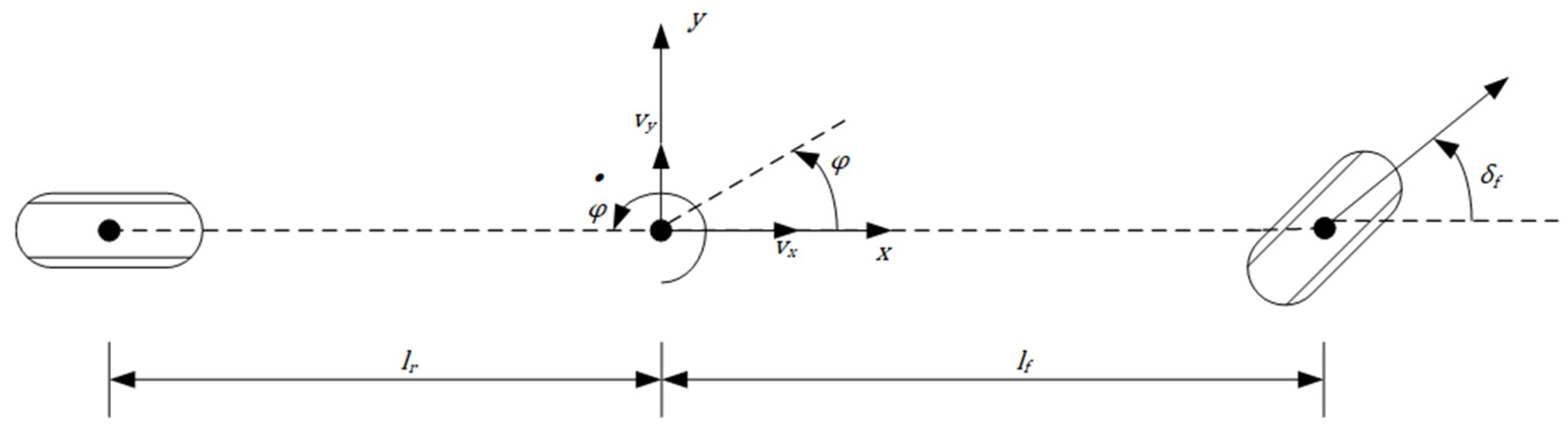
2.1. Vehicle Dynamics Model

In vehicle motion, building an accurate vehicle model can improve vehicle tracking control. The coupling between lateral and longitudinal control is added to the vehicle model, and the tire slip is considered, which can effectively control the vehicle to track the reference trajectory [40]. Therefore, a vehicle dynamics model considering tire slip is established in this paper [41], as shown in Figure 1.
The force analysis of the above vehicle model can obtain the expression of the nonlinear dynamic model of the vehicle:
{ m v y ˙ = m v x φ ˙ + 2 [ C c f ( δ f v y + l f φ ˙ v x ) + C c r l r φ ˙ v y v x ] m v x ˙ = m v y φ ˙ + 2 [ C l f s f C c f ( δ f v y + l f φ ˙ v x ) δ f + C l r s r ] I z φ ¨ = 2 [ l f C c f ( δ f v y + l f φ ˙ v x ) l r C c r l r φ ˙ v y v x ] Y ˙ = v x sin φ + v y cos φ X ˙ = v x cos φ v y sin φ
where m is the vehicle mass, v x and v y are the longitudinal and lateral speeds of the center of mass in the body coordinate system, I z is the moment of inertia around the Z axis, φ is the yaw angle, l f and l r are the distances from the center of mass of the vehicle to the front and rear axles, δ f is the front wheel steering angle, C l f and C l r are the longitudinal slip stiffness of the front and rear tires, C c f and C c r are the lateral slip stiffness of the front and rear tires, s f and s r are the slip ratios of the left and right front wheels.
Since all of the state points on the predicted trajectory cannot be obtained, the nonlinear dynamic model should be linearized. In this paper, ξ ˙ = F ( ξ ( t ) , u ( t ) ) is taken and a system operating point is selected as [ ξ 0 , u 0 ] , the first-order Taylor formula is expanded at the operating point to obtain the linear time-varying equation:
ξ ˙ = A t ξ ( t ) + B t u ( t )
Among them, A t = F ξ ; B t = F u .
The Formula (2) is discretized to obtain the discrete state expression:
ξ ( k + 1 ) = A k ξ ( k ) + B k u ( k ) + ξ 0 ( k + 1 ) A k ξ 0 ( k ) B k u 0 ( k )
η ( k ) = C ξ ( k )
Among them, A k = I + A t × T , B k = B t × T , I is the identity matrix, T is the sampling period of the system.

2.2. Design Objective Function

In this paper, the model state quantity is [ Y ˙ , X ˙ , φ , φ ˙ , Y , X ] and the control quantity is the front wheel steering angle δ f . In order to reduce the amount of calculation and ensure that the controller can effectively track the trajectory, the following objective function with constraints is specially adopted:
J = 1 2 [ Δ u ε ] T H [ Δ u     ε ] + f T [ Δ u ε ] + E T Q ˜ E s . t .   u m i n u t + A I u u m a x Y m i n Y Y m a x
Among them, H = [ 2 ( Θ T Q Θ + R ) 0 0 2 ρ ] , f = [ 2 E T Q Θ 0 ] , E = Y r e f ψ ε T ϕ , Q ˜ = d i a g ( Q , Q , Q ,   ... ) , E is the tracking error between the desired path in the predicted time domain and the free response of the system, ε is the relaxation factor, Δ u is the control increment, ψ is a N p × 1   linear time-varying matrix, ϕ is the deviation augmentation matrix.
In lateral tracking capability, the constraint condition of the front wheel steering angle δ f is set as: 25 ° δ f + 25 ° .

2.3. Power Battery Energy Consumption
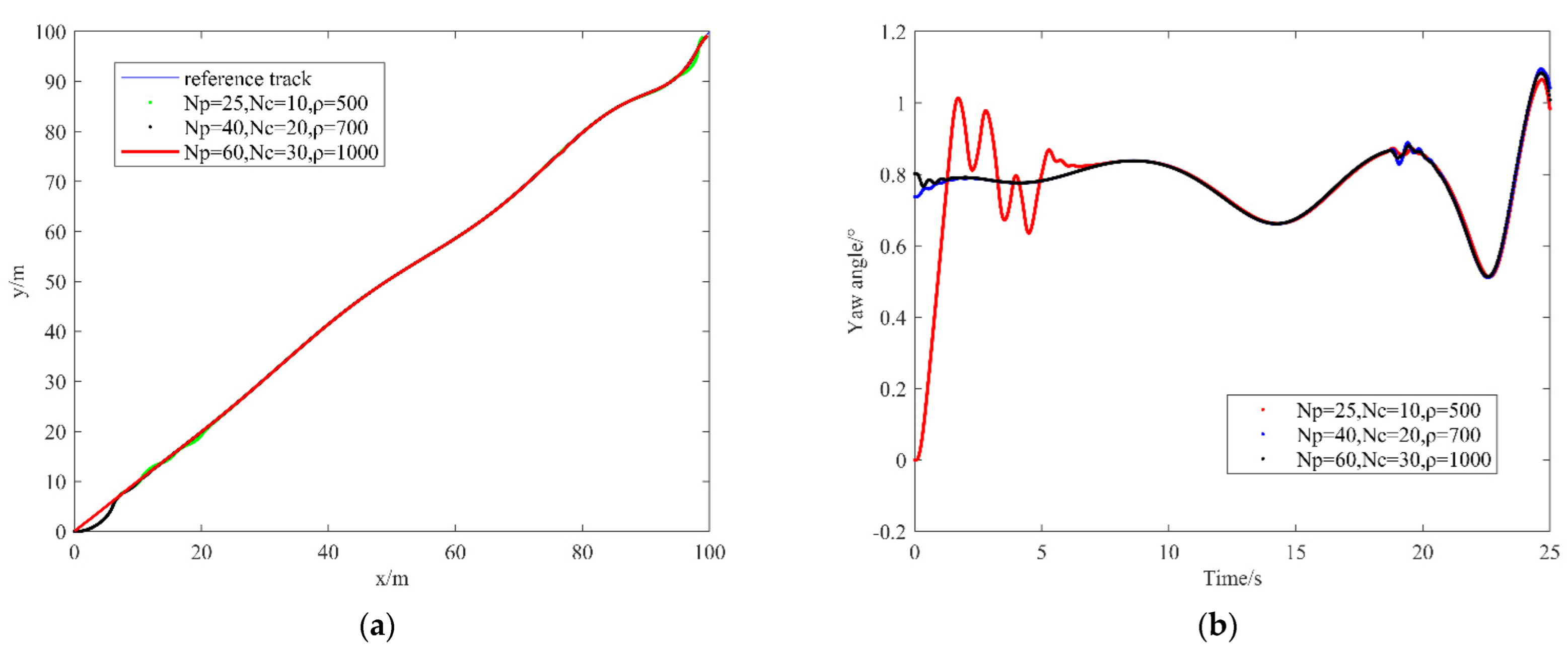
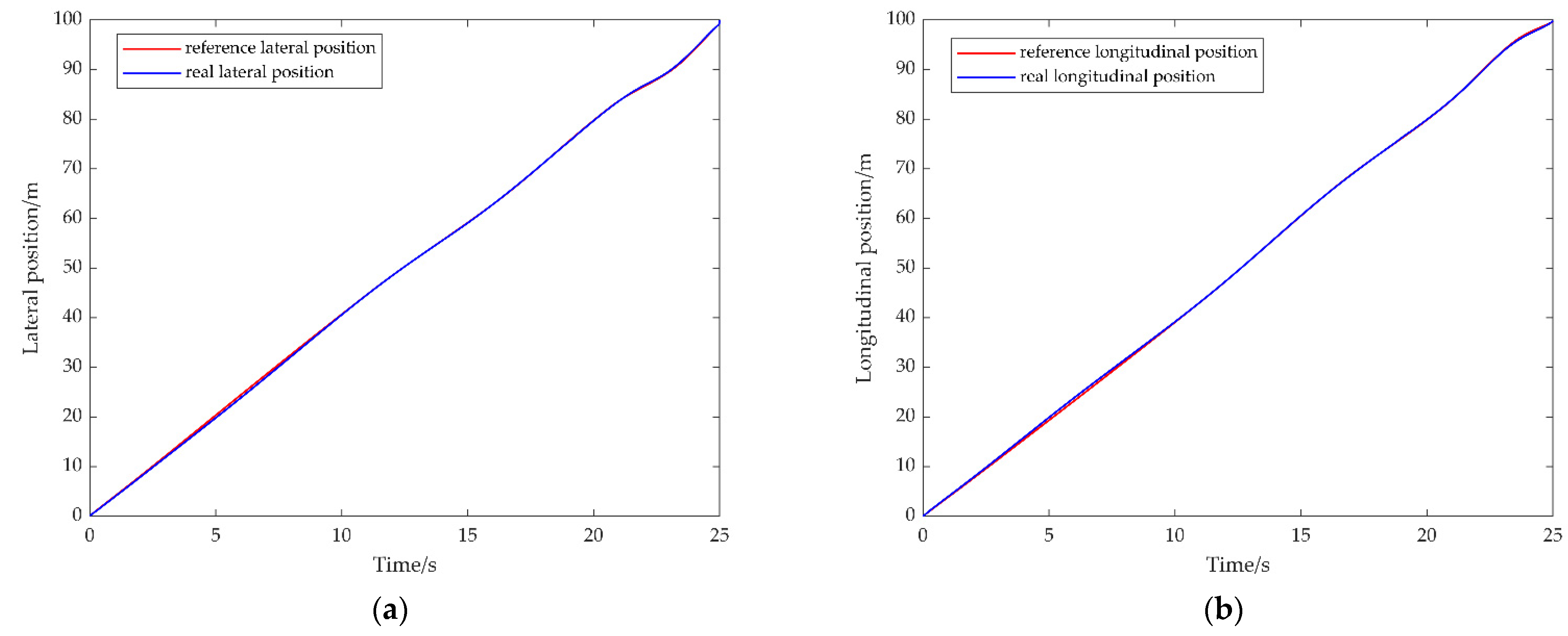
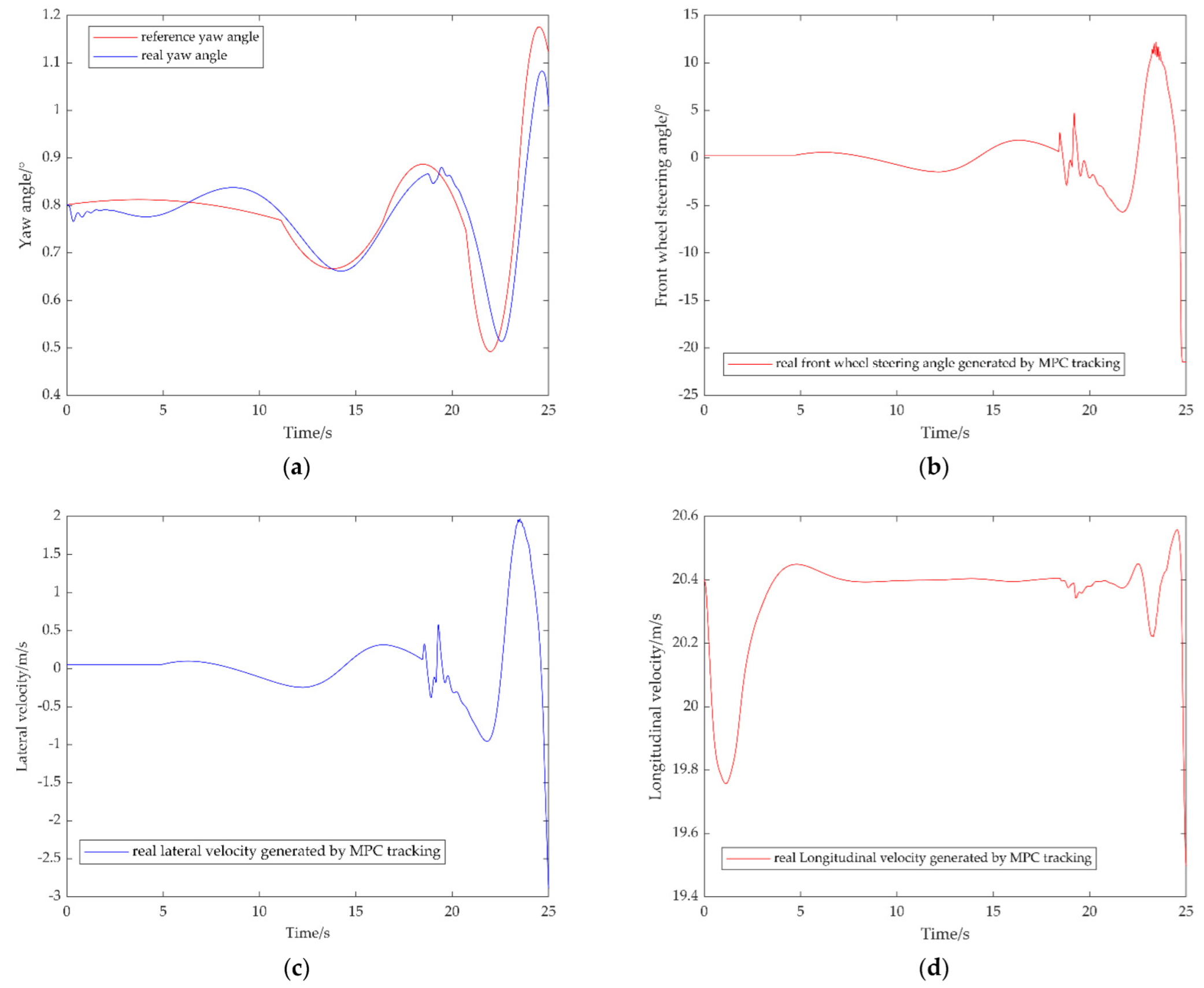
In order to better verify the electricity consumption of the MPC trajectory tracking controller to control the automated vehicle during the driving mileage. In this paper, the actual driving distance of the vehicle is divided into several segments, and each segment of the actual driving distance is multiplied by a fixed battery electricity consumption rate to get the actual battery power consumption of the vehicle in that segment. For this purpose, this paper adopts the following electricity consumption expression:
Q = d i w
Among them, i   = 1, 2, 3, …, d   is the actual driving distance of the vehicle, w   is electricity consumption rate ( w = 0.22   kWh / km ) [42].

3. Results

This paper uses the co-simulation of Carsim and Simulink, builds the vehicle dynamics module and determines the input and output ports in Carsim, and builds the trajectory tracking control module in Simulink. The main parameters of the trajectory tracking controller are shown in Table 1.
The accuracy and stability of trajectory tracking are affected by the prediction time domain and the control time domain to a certain extent. Based on the constant sampling time of the system, in order to verify the effects of different weight coefficients, prediction time domain and control time domain on the vehicle tracking trajectory, this paper uses the automated vehicles trajectory planned by the artificial potential field method as the reference trajectory [43] and selects three different sets of data to test the efficiency of the vehicle tracking trajectory.
It can be seen from Figure 2a,b that when N p = 25 , N c = 10 , and ρ = 500 , the vehicle cannot accurately track the reference trajectory in the interval of 0–20 and a lot of fluctuations occur. The yaw angle generated by the actual driving of the vehicle also has a lot of fluctuations, and the vehicle stability is poor. When N p = 40 , N c = 20 , and ρ = 700 , the tracking accuracy and stability of the controller are only slightly improved, and it still cannot satisfy the normal driving of the vehicle. When N p = 60 , N c = 30 , and ρ = 1000 , the vehicle can accurately track the reference trajectory from the starting position and reach the target position smoothly. During the whole tracking process, the actual driving trajectory of the vehicle has no fluctuation and the actual driving trajectory has a high degree of coincidence with the reference trajectory, it can also track well at the turning of the reference trajectory. Through the comparison and analysis of the above three sets of data, when the sampling time of the system remains unchanged, the relaxation factor weight coefficient, prediction time domain and control time domain parameters in the MPC controller designed in this paper are selected as N p = 60 , N c = 30 , and ρ = 1000 .
Figure 3a,b shows the comparison between the reference trajectory and the real trajectory in the lateral and longitudinal positions respectively. Figure 3a compares the lateral positions of the reference trajectory and the real trajectory, it can be seen that deviations occur in the 0–10 s and 20–25 s intervals. Figure 3b compares the longitudinal positions of the reference trajectory and the real trajectory, it can be seen that deviations occur in the 0–10 s interval. The deviations in the above comparisons are extremely small and are within the controllable range, which does not affect the overall tracking effect, which shows that the controller has very good robustness.
Figure 4a shows the comparison between the reference yaw angle and the actual gen− erated yaw angle, there are slight fluctuations in the actual generated yaw angle. The de− viation between the reference yaw angle and the actual generated yaw angle is less than 0.2° during the whole simulation time, which indicates the high accuracy of the MPC con− troller. Figure 4b represents the front wheel steering angle generated by the actual driving of the vehicle. According to the set of constraints, the front wheel steering angle: 25 ° δ f + 25 ° . As can be seen from the figure, the actual generated front wheel steering angle fluctuation range is in accordance with the set constraints. The lateral and longitudinal velocity curves actually generated by the vehicle in Figure 4c,d fluctuate slightly, but the range of fluctuation is extremely small and within a controllable range. Combining the lateral speed curve and the wheel angle curve, it can be seen that when the lateral speed fluctuates, the front wheel angle generated by the vehicle is still within the controllable range. Combining the lateral velocity curve and the actually generated yaw angle curve, it can be seen that when the lateral velocity fluctuates, the vehicle can keep up with the reference trajectory in time after deviating from the heading. This further illustrates that the designed controller can effectively control the steering of the vehicle and improve the accuracy of the vehicle when tracking the reference trajectory.
Figure 5 shows the comparison between the reference electricity consumption and the actual electricity consumption of the vehicle during the specified driving mileage. In the entire driving mileage, the actual electricity consumption is almost the same as the reference electricity consumption, and the error between the two is very small. This shows that the battery energy consumption is also within the reference range, and the loss is extremely small. The above results show that the vehicle’s accurate tracking of the trajec− tory is beneficial to save electricity and improve the battery cruising range.

4. Conclusions

Based on the vehicle dynamics model, this paper uses model predictive control theory to design an automated vehicle trajectory tracking controller, in which appropriate constraints are added to ensure that the vehicle can accurately track the reference trajectory. After simulation and comparison the automated vehicle trajectory tracking controller designed in this paper can quickly complete the trajectory tracking task and substantially reduce the deviation between the real trajectory and the reference trajectory in the lateral and longitudinal positions. The reduction of this deviation is conducive to reducing the energy consumption of the power battery of the automated vehicle and improving the cruising rang of the power battery and the energy utilization rate of the vehicle. The controller has a quite high accuracy during trajectory tracking.

Author Contributions

Conceptualization, H.M., W.P. and Q.Z.; methodology, H.M. and W.P.; software, H.M.; validation, H.M., W.P. and Q.Z.; formal analysis, H.M., W.P. and Q.Z.; investigation, H.M. and W.P.; resources, H.M.; data curation, H.M., W.P. and Q.Z.; writing—original draft preparation, H.M.; writing—review and editing, W.P. and Q.Z.; visualization, H.M. and W.P.; supervision, W.P. and Q.Z.; project administration, W.P. and Q.Z.; funding acquisition, W.P. and Q.Z. All authors have read and agreed to the published version of the manuscript.

Funding

This research was funded by Shandong Provincial Natural Science Foundation, grant number ZR2020QF059, ZR2021MF131; Foundation of State Key Laboratory of Automotive Simulation and Control, grant number 20181119.

Institutional Review Board Statement

Not applicable.

Informed Consent Statement

Not applicable.

Data Availability Statement

Not applicable.

Conflicts of Interest

The authors declare no conflict of interest.

References

  1. Hariharan, C.; Gunadevan, D.; Prakash, S.A. Simulation of battery energy consumption in an electric car with traction and HVAC model for a given source and destination for reducing the range anxiety of the driver. Energy 2022, 249, 123657. [Google Scholar] [CrossRef]
  2. Cetin, M.S.; Güler, H.; Gençoğlu, M.T. Fuzzy Logic Based Battery Control System Design for Electric Vehicles. In Proceedings of the Innovations in Intelligent Systems and Applications Conference (ASYU), Elazig, Turkey, 6–8 October 2021; pp. 1–4. [Google Scholar]
  3. Hoekstra, F.S.J.; Bergveld, H.J.; Donkers, M.C.F. Optimal Control of Active Cell Balancing: Extending the Range and Useful Lifetime of a Battery Pack. IEEE Trans. Control. Syst. Technol. 2022, 1–8. [Google Scholar] [CrossRef]
  4. He, C.; Li, M.; Wang, F. Simulation study of a cylindrical battery module. J. Energy Storage 2022, 48, 104000. [Google Scholar] [CrossRef]
  5. Ruhani, B.; Abidi, A.; Hussein, A.K. Numerical simulation of the effect of battery distance and inlet and outlet length on the cooling of cylindrical lithium-ion batteries and overall performance of thermal management system. J. Energy Storage 2022, 45, 103714. [Google Scholar] [CrossRef]
  6. Khiari, J.; Olaverri-Monreal, C. Uncertainty-Aware Prediction of Battery Energy Consumption for Hybrid Electric Vehicles. arXiv 2022, arXiv:2204.12825. [Google Scholar]
  7. Sagaria, S.; Neto, R.C.; Baptista, P. Modelling approach for assessing influential factors for EV energy performance. Sustain. Energy Technol. Assess. 2021, 44, 100984. [Google Scholar] [CrossRef]
  8. Babu, A.R.; Minovski, B.; Sebben, S. Thermal encapsulation of large battery packs for electric vehicles operating in cold climate. Appl. Therm. Eng. 2022, 212, 118548. [Google Scholar] [CrossRef]
  9. Ma, Y.; Ding, H.; Liu, Y. Battery thermal management of intelligent-connected electric vehicles at low temperature based on NMPC. Energy 2022, 244, 122571. [Google Scholar] [CrossRef]
  10. Singirikonda, S.; Obulesu, Y.P. Battery modelling and state of charge estimation methods for Energy Management in Electric Vehicle-A review. IOP Conf. Ser. Mater. Sci. Eng. 2020, 937, 012046. [Google Scholar] [CrossRef]
  11. Kebbati, Y.; Ait-Oufroukh, N.; Vigneron, V.; Ichalal, D. Optimized self-adaptive PID speed control for autonomous vehicles. In Proceedings of the International Conference on Automation and Computing, Portsmouth, UK, 2–4 September 2021; pp. 1–6. [Google Scholar]
  12. Tian, M.W.; Yan, S.R.; Mohammadzadeh, A. Stability of Interval Type-3 Fuzzy Controllers for Autonomous Vehicles. Mathematics 2021, 9, 2742. [Google Scholar] [CrossRef]
  13. Dong, X.P.; Pei, H.Y.; Gan, M. Autonomous Vehicle Lateral Control Based on Fractional-order PID. In Proceedings of the Information Technology, Networking, Electronic and Automation Control Conference, Xi’an, China, 15–17 October 2021; Volume 5, pp. 830–835. [Google Scholar]
  14. Zuñiga-Peña, S.; Hernández-Romero, N.; Seck-Tuoh-Mora, C. Improving 3D Path Tracking of Unmanned Aerial Vehicles through Optimization of Compensated PD and PID Controllers. Appl. Sci. 2021, 12, 99. [Google Scholar] [CrossRef]
  15. Mao, J.; Yang, L.; Hu, Y.B.; Liu, K.; Du, J.F. Research on Vehicle Adaptive Cruise Control Method Based on Fuzzy Model Predictive Control. Machines 2021, 9, 160. [Google Scholar] [CrossRef]
  16. Yang, J.R.; Peng, W.F.; Sun, C. A Learning Control Method of Automated Vehicle Platoon at Straight Path with DDPG-Based PID. Electronics 2021, 11, 617. [Google Scholar] [CrossRef]
  17. Ma, Y.; Zhang, W.Q.; Qureshi, W.S. Autonomous navigation for a wolfberry picking robot using visual cues and fuzzy control. Inf. Process. Agric. 2021, 8, 15–26. [Google Scholar] [CrossRef]
  18. Yatak, M.Ö.; Şahin, F. Ride Comfort-Road Holding Trade-off Improvement of Full Vehicle Active Suspension System by Interval Type-2 Fuzzy Control. Eng. Sci. Technol. Int. J. 2021, 24, 259–270. [Google Scholar] [CrossRef]
  19. Lei, Y.L.; Wen, G.; Fu, Y.; Li, X.; Hou, B.; Geng, X. Trajectory-following of a 4WID-4WIS vehicle via feedforward–backstepping sliding-mode control. Proc. Inst. Mech. Eng. Part D J. Automob. Eng. 2022, 236, 322–333. [Google Scholar] [CrossRef]
  20. Subroto, R.K.; Wang, C.Z.; Lian, K.L. Four-wheel independent drive electric vehicle stability control using novel adaptive sliding mode control. IEEE Trans. Ind. Appl. 2020, 56, 5995–6006. [Google Scholar] [CrossRef]
  21. Peng, B.; Yu, D.; Zhou, H.; Xiao, X.; Fang, Y. A platoon control strategy for autonomous vehicles based on sliding-mode control theory. IEEE Access 2020, 8, 81776–81788. [Google Scholar] [CrossRef]
  22. Ao, D.; Huang, W.; Wong, P.K.; Li, J. Robust Backstepping Super-Twisting Sliding Mode Control for Autonomous Vehicle Path Following. IEEE Access 2021, 9, 123165–123177. [Google Scholar] [CrossRef]
  23. Abooee, A.; Hayeri Mehrizi, M.; Arefi, M.M.; Yin, S. Finite-time sliding mode control for a 3-DOF fully actuated autonomous surface vehicle. Trans. Inst. Meas. Control. 2021, 43, 371–389. [Google Scholar] [CrossRef]
  24. Lu, Z.; Shyrokau, B.; Boulkroune, B.; Van Aalst, S.; Happee, R. Performance benchmark of state-of-the-art lateral path-following controllers. In Proceedings of the 2018 IEEE 15th International Workshop on Advanced Motion Control (AMC), Tokyo, Japan, 9–11 March 2018; pp. 541–546. [Google Scholar]
  25. Nebeluk, R.; Ławryńczuk, M. Computationally Simple Nonlinear MPC Algorithm for Vehicle Obstacle Avoidance with Minimization of Fuel Utilization. IEEE Access 2021, 9, 17296–17311. [Google Scholar] [CrossRef]
  26. Cheng, S.; Li, L.; Chen, X.; Wu, J.; Wang, H.D. Model-Predictive-Control-Based Path Tracking Controller of Autonomous Vehicle Considering Parametric Uncertainties and Velocity-Varying. IEEE Trans. Ind. Electron. 2021, 68, 8698–8707. [Google Scholar] [CrossRef]
  27. Li, Z.H.; Wang, P.; Liu, H.H.; Hu, Y.F.; Chen, H. Coordinated longitudinal and lateral vehicle stability control based on the combined-slip tire model in the MPC framework. Mech. Syst. Signal Process. 2021, 161, 107947. [Google Scholar] [CrossRef]
  28. Ammour, M.; Orjuela, R.; Basset, M. Collision avoidance for autonomous vehicle using MPC and time varying Sigmoid safety constraints. IFAC-PapersOnLine 2021, 54, 39–44. [Google Scholar] [CrossRef]
  29. Pang, H.; Liu, N.; Hu, C.; Xu, Z.J. A practical trajectory tracking control of autonomous vehicles using linear time-varying MPC method. Proc. Inst. Mech. Eng. Part D J. Automob. Eng. 2022, 236, 709–723. [Google Scholar] [CrossRef]
  30. Jeong, Y.h.; Yim, S.J. Model Predictive Control-Based Integrated Path Tracking and Velocity Control for Autonomous Vehicle with Four-Wheel Independent Steering and Driving. Electronics 2021, 10, 2812. [Google Scholar] [CrossRef]
  31. Chen, C.P.; Guo, J.H.; Guo, C.; Chen, C.Y.; Zhang, Y.; Wang, J.W. Adaptive Cruise Control for Cut-In Scenarios Based on Model Predictive Control Algorithm. Appl. Sci. 2021, 11, 5293. [Google Scholar] [CrossRef]
  32. Zhang, K.W.; Sun, Q.; Shi, Y. Trajectory tracking control of autonomous ground vehicles using adaptive learning MPC. IEEE Trans. Neural Netw. Learn. Syst. 2021, 32, 5554–5564. [Google Scholar] [CrossRef]
  33. Pae, D.S.; Kim, G.H.; Kang, T.K.; Lim, M.T. Path planning based on obstacle-dependent gaussian model predictive control for autonomous driving. Appl. Sci. 2021, 11, 3703. [Google Scholar] [CrossRef]
  34. Xu, Y.; Tang, W.T.; Chen, B.Y.; Qiu, L.; Yang, R. A model predictive control with preview-follower theory algorithm for trajectory tracking control in autonomous vehicles. Symmetry 2021, 13, 381. [Google Scholar] [CrossRef]
  35. Chen, S.; Chen, H.; Negrut, D. Implementation of MPC-Based Trajectory Tracking Considering Different Fidelity Vehicle Models. J. Beijing Inst. Technol. 2020, 29, 303–316. [Google Scholar]
  36. Lazcano, A.M.R.; Niu, T.; Akutain, X.C.; Cole, D.; Shyrokau, B. MPC-Based Haptic Shared Steering System: A Driver Modeling Approach for Symbiotic Driving. IEEE/ASME Trans. Mechatron. 2021, 26, 1201–1211. [Google Scholar] [CrossRef]
  37. Chen, S.; Chen, H. MPC-based path tracking with PID speed control for autonomous vehicles. IOP Conf. Ser. Mater. Sci. Eng. 2020, 892, 012034. [Google Scholar] [CrossRef]
  38. Xu, J.; Zhang, B.; Zhu, X.; Su, Y. Linear Time-Varying MPC Vehicle Trajectory Tracking Controller Considering Driving Road Surface Factors. In Proceedings of the International Conference on Control Science and Electric Power Systems (CSEPS), Shanghai, China, 28–30 May 2021; pp. 83–88. [Google Scholar]
  39. Liang, Y.; Li, Y.; Khajepour, A.; Huang, Y.; Qin, Y.; Zheng, L. A Novel Combined Decision and Control Scheme for Autonomous Vehicle in Structured Road Based on Adaptive Model Predictive Control. IEEE Trans. Intell. Transp. Syst. 2022, 1–15. [Google Scholar] [CrossRef]
  40. Chowdhri, N.; Ferranti, L.; Iribarren, F.S.; Shyrokau, B. Integrated nonlinear model predictive control for automated driving. Control. Eng. Pract. 2021, 106, 104654. [Google Scholar] [CrossRef]
  41. Gong, J.W. Model Predictive Control of Unmanned Vehicles, 2nd ed.; Beijing Institute of Technology Press: Beijing, China, 2020; pp. 38–39. [Google Scholar]
  42. Liu, Q.; Liu, J.H.; Le, W.W.; Guo, Z.X.; He, Z.G. Data-driven intelligent location of public charging stations for electric vehicles. J. Clean. Prod. 2019, 232, 531–541. [Google Scholar] [CrossRef]
  43. Liu, B.Y.; Ye, X.B.; Wang, X.B. Path Avoidance Algorithm for Unmanned Ground Vehicles Based on Improved Artificial Potential Field. Chin. J. Inert. Technol. 2020, 28, 769–777. [Google Scholar]
Figure 1. Vehicle dynamics model.
Electrochem 03 00023 g001
Figure 2. (a) Simulation of vehicle tracking reference trajectory with different controller parameters; (b) The yaw angle generated by the vehicle tracking the reference trajectory when the controller parameters are different.
Electrochem 03 00023 g002
Figure 3. (a) Comparison of the lateral position of the reference track and the real track; (b) comparison of the longitudinal position of the reference track and the real track.
Electrochem 03 00023 g003
Figure 4. (a) Comparison of reference yaw angle and real yaw angle; (b) generated front wheel steering angle; (c) generated lateral velocity; (d) generated longitudinal velocity.
Electrochem 03 00023 g004
Figure 5. Battery power consumption while the vehicle is running.
Electrochem 03 00023 g005
Table 1. Controller parameters.
VariableName and UnitNumerical Value
N p Prediction time domain60
N c Control time domain30
T Sampling period/s0.02
ρ Relaxation factor weight coefficient1000
m Vehicle mass/kg1723
l f Front wheelbase/m1.232
l r Rear wheelbase/m1.468
I z Moment   of   inertia / kg · m 2 4175
C c f Front wheel lateral cornering stiffness66,900
C c r Rear wheel lateral cornering stiffness62,700
C l f Front wheel longitudinal cornering stiffness66,900
C l r Rear wheel longitudinal cornering stiffness62,700
Publisher’s Note: MDPI stays neutral with regard to jurisdictional claims in published maps and institutional affiliations.

