Article

Synthesis of Nickel Fumarate and Its Electrochemical Properties for Li-Ion Batteries

1
Department of Applied Chemistry, Tokyo University of Science, Tokyo 162-8601, Japan
2
Graphene Labs, Istituto Italiano di Tecnologia, Via Morego 30, 16163 Genova, Italy
3
Department of Chemistry and Earth Sciences, Qatar University, Doha P.O. Box 2713, Qatar
4
Department of Mining and Materials Engineering, McGill University, Wong Building, 3610 University Street, Montreal, QC H3A OC5, Canada
5
Centre of Excellence in Transportation Electrification and Energy Storage (CETEES), Institute of Research Hydro-Québec, 1806, Lionel-Boulet Blvd., Varennes, QC J3X 1S1, Canada
*
Authors to whom correspondence should be addressed.
Electrochem 2021, 2(3), 439-451; https://doi.org/10.3390/electrochem2030029
Submission received: 28 June 2021 / Revised: 15 July 2021 / Accepted: 19 July 2021 / Published: 27 July 2021
(This article belongs to the Collection Feature Papers in Electrochemistry)

Abstract

:
Metal–organic frameworks (MOFs) have found a potential application in various domains such as gas storage/separation, drug delivery, catalysis, etc. Recently, they have found considerable attention for energy storage applications such as Li- and Na-ion batteries. However, the development of MOFs is plagued by their limited energy density that arises from high molecular weight and low volumetric density. The choice of ligand plays a crucial role in determining the performance of the MOFs. Here, we report a nickel-based one-dimensional metal-organic framework, NiC4H2O4, built from bidentate fumarate ligands for anode application in Li-ion batteries. The material was obtained by a simple chimie douce precipitation method using nickel acetate and fumaric acid. Moreover, a composite material of the MOF with reduced graphene oxide (rGO) was prepared to enhance the lithium storage performance as the rGO can enhance the electronic conductivity. Electrochemical lithium storage in the framework and the effect of rGO on the performance have been investigated by cyclic voltammetry, galvanostatic charge–discharge measurements, and EIS studies. The pristine nickel formate encounters serious capacity fading while the rGO composite offers good cycling stability with high reversible capacities of over 800 mAh g1.

1. Introduction

The advancement of Li-ion batteries (LIBs) has revolutionised the portable electronics industry as LIBs ensure compact and lightweight power sources owing to their high energy density. Current commercial LIBs predominantly use graphite as an anode material with a limited theoretical capacity of 372 mAh g−1. This generates immense interest to increase the capacity of electrode materials [1,2,3]. For example, an alloying-based electrode such as Si can deliver a very high capacity of 4000 mAh g−1 [4,5,6,7,8]. Other high-capacity materials of interest are conversion-based anode materials such as oxides and metal-organic materials. Recently, Metal oxides and its carbon composites, metal–organic frameworks (MOFs) [9,10,11,12,13,14,15,16,17,18,19,20,21,22,23,24,25,26,27,28,29,30,31,32] have gained a considerable attraction as electrode materials for LIBs. These MOFs or coordination polymers (CPs) are crystalline materials with important properties such as high porosity/surface area, good chemical stability, and tunable functionality. Ferey et al. reported an iron-based MOF, Fe(O2C-C6H4-CO2)(OH)0.8F0.2 (MIL-53) as a cathode material for LIBs [33]. It could reversibly intercalate 0.6 moles of Li per formula owing to the Fe2+/3+ redox couple without any destruction of the crystal structure, demonstrating that MOF can be used for energy storage. Maiti et al. demonstrated reversible lithium cycling in different BTC (1,3,5-benzenetricarboxylate)-based MOFs. High reversible capacities of 694 and 740 mAh g−1 were obtained for Mn and Cu MOFs, respectively [34,35]. Hu et al. showed that an Mn-BDC MOF exhibits high anodic capability for LIBs, with a reversible capacity of 870 mAh g−1 at a current density of 100 mA g−1 [36]. Saravanan et al. investigated simple formate bridged MOFs with diamondoid topology for LIB anodes [37]. It was reported that the MOF undergoes reversible lithium storage via the conversion mechanism with the formation of lithium formate. Gou et al. reported a CNT composite of nickel formate, which exhibits enhanced lithium storage with a capacity of over 900 mAh g−1 [38]. Tirado et al. introduced metal oxalates as novel anode materials for LIBs. Different metal oxalates, MC2O4 (M = Fe, Mn, Co, Ni, Cu, Sn) have been reported [39,40,41]. Conversion of metal oxalate to lithium oxalate and respective metals was suggested as the possible mechanism of reversible lithium storage in these oxalates. Metal oxalates have a higher molecular weight, compared to the corresponding metal oxides and hence have a lesser theoretical capacity. However, they were found to exhibit higher capacities of over 800 mAh g−1, though the reasons are not clear. It was noticed that capacitive effects contribute substantially to these materials, in addition to the faradaic capacity resulting from the conversion reaction [39,40]. In a recent report, Wang et al. investigated aluminium fumarate as an anode for LIBs, which exhibited a reversible capacity of 392 mAh g−1 at a current density of 37.5 mA g−1 [42].
In this study, we demonstrate the lithium storage characteristics of a nickel-based one-dimensional metal-organic framework (1D-MOF). Nickel fumarate tetrahydrate and its composite with rGO were prepared by a simple precipitation method. Investigation of the electrochemical properties of the dehydrated samples reveals that the rGO composite exhibits a reversible capacity of ~800 mAh g−1 at 0.2 C current rate after 60 cycles.

2. Experimental

2.1. Materials and Methods

Nickel (II) acetate tetrahydrate (99%, Fluka, Munich, Germany), fumaric acid (98%, Sigma-Aldrich, Burlington, MA, USA), and methanol (99.8%, Sigma-Aldrich, Burlington, MA, USA) were used for the synthesis. For the synthesis of graphene oxide (GO), graphite powder (Sigma-Aldrich, Burlington, MA, USA, 99%), sulphuric acid (98%, Sigma-Aldrich, Burlington, MA, USA), sodium nitrate (BDH, Poole, UK, 98%), phosphoric acid (BDH, Poole, UK, 99%), potassium permanganate (Sigma-Aldrich, Burlington, MA, USA, 99%) were used.
Nickel fumarate tetrahydrate was prepared by a precipitation reaction at room temperature using nickel acetate and fumaric acid. Firstly, a solution of nickel acetate (0.2 M) and a solution of fumaric acid (0.2 M) were prepared separately in methanol. Then, 50 mL of metal acetate solution was added slowly to 100 mL of fumaric acid (1:2 molar ratio of metal:ligand) with continuous stirring. After the complete addition of nickel acetate, the solution turned cloudy. Further stirring for one hour resulted in a bluish-green precipitate of nickel fumarate tetrahydrate. The precipitate was collected by centrifugation and washed a few times with methanol to remove any unreacted fumaric acid present in the product. The powder was dried at 40 °C in the air and used for further studies. An anhydrous phase was obtained by dehydration at 180 °C, which was used for battery testing and for clarity, referred to as NiFum.
A composite of nickel fumarate with rGO was prepared as follows: Graphene oxide was prepared according to the reported procedure, with some modifications [43]. The as-synthesised nickel fumarate powder (500 mg) was dispersed in 20 mL of deionised water by sonication using a small amount of PVP (10 mg). Then, graphene oxide (0.2 wt%) solution was added and homogenised by magnetic stirring for an hour. Then, 100 mL of methanol was added to the mixture and subjected to microwave irradiation (100 °C for 5 min) which resulted in a black precipitate. It was washed using methanol and dried at 40 °C in the air. An anhydrous composite, for clarity referred to as G-NiFum, was obtained by dehydration at 180 °C. The content of rGO in the composite has been calculated to be ~2 wt% from CHNS analysis.

2.2. Materials Characterisation

Powder X-ray Diffraction (PXRD), Fourier transform infrared spectroscopy (FT-IR), Raman spectroscopy, and thermogravimetric analysis (TGA) were used. PXRD patterns were recorded on a Bruker D8 Advance diffractometer using a Cu-Kα source. TGA experiments were performed in a nitrogen atmosphere at a ramping rate of 10 °C min−1 using PerkinElmer’s TGA 4000 thermogravimetric analyser.
The microstructure of the samples was analysed using scanning electron microscopy (SEM), transmission electron microscopy (TEM), and adsorption studies. The surface area of the samples preheated to 150 °C was determined from nitrogen adsorption isotherms at 77 K using a Micromeritics Tristar instrument. SEM micrographs of platinum-coated samples were captured using JEOL JSM-6700F field emission scanning electron microscope (FESEM) operated at 5 kV and 10 µA. JEOL JEM 2010 transmission electron microscope was used to record the TEM images of the materials.

Electrochemical Characterisation

Electrochemical properties of the samples were investigated in coin cells (type 2016) with Li metal (Kyokuto Metal Co., Tokyo, Japan) as a counter electrode, Celgard polypropylene membrane as the separator, and 1 M LiPF6 dissolved in ethylene carbonate (EC) and diethyl carbonate (DEC) (1:1 v/v, Merck) as the electrolyte. The active materials (70 wt%) were mixed with a conducting additive, super P carbon (15 wt%), and 15 wt% of polyvinylidene difluoride (PVDF) binder (Kynar 2801). A slurry was prepared in N-methyl pyrrolidinone (NMP) solvent and was uniformly coated onto an etched copper foil of 10 µm thickness. It was dried overnight and cut into circular discs of 16 mm diameter. The electrodes were used to make Li-half cells in an Ar-filled glove box (MBraun, Stratham, NH, USA) by crimp sealing. Cyclic voltammetry was carried out using the Solartron cell test system, and Bitrode multiple battery tester was used for galvanostatic charge–discharge studies [44]. The Solartron 1260 A impedance analyser was used to carry out electrochemical impedance spectroscopy (EIS) studies of the cells in a frequency range of 350 kHz to 0.001 Hz, Ac amplitude: 10 mV.

3. Results and Discussion

3.1. Structure and Morphology

The nickel fumarate was precipitated in a one-dimensional polymeric structure, as confirmed from its powder X-ray diffraction (PXRD) pattern (Figure 1a). All the diffraction peaks are in good agreement with the simulated pattern of a nickel fumarate tetrahydrate, Ni(C4H2O4)(H2O)4, reported in the literature [45]. It crystallises in the monoclinic space group (P21/c). In the material, each nickel atom exhibits octahedral coordination, with the oxygen of four water molecules and two different fumarate ligands in trans position, resulting in the 1D framework. The crystallographic representation of the polymeric structure of nickel fumarate tetrahydrate is depicted in Figure 1a. The rGO composite was characterised by a similar set of peaks (Figure 1a) as the pristine sample, indicating that there is no phase change during the preparation of the composite. It is notable that both samples exhibit good crystallinity, evident from the sharp peaks.
The thermogravimetric analysis profiles of NiFum are shown in Figure 1b. The pristine material shows a weight loss of 26.2% in the temperature range of 90–230 °C corresponding to the loss of water molecules which are coordinated to Ni. As can be seen from the figure, dehydration occurs in two steps. As the PXRD patterns confirmed the formation of a tetrahydrate, the calculated weight loss for the removal of 1b water molecules from the material should be 29.4%. However, the observed weight loss was 26.2%, indicating that partial dehydration occurred during the process of drying. The subsequent weight loss of ~40% in 330–420 °C can be attributed to the decomposition of the organic ligand. The presence of rGO in the composite is also confirmed from its Raman spectrum (Figure 1c. It can be used as a tool to analyse the degree of reduction of GO. The D and G bands appeared at 1331 and 1588 cm−1, respectively, for G-NiFum. The ID/IG ratio of the composite increases considerably, compared to GO which indicates the in situ reduction of GO to amorphous carbon/few layer graphene like carbon during the synthesis [44,46,47,48]. Microwave-assisted heating has been reported as a technique for the reduction of GO, and it is expected that the nickel fumarate particles are first anchored onto the GO sheets, and during the microwave irradiation, the GO sheets were reduced to rGO.
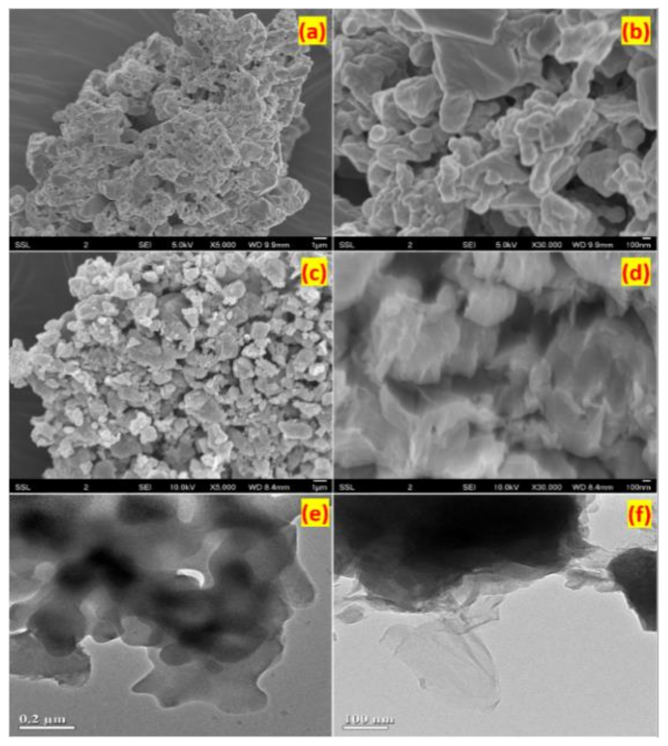
SEM and TEM images of NiFum are shown in Figure 2. The images indicate that the sample consists of submicron-sized particles of size around 100–500 nm that are fused together to form bigger particles (Figure 2a,b). The particle size is further confirmed from the TEM image (Figure 2e). The rGO composite contains nickel fumarate particles of the same size but which are anchored on reduced graphene oxide sheets, as confirmed by the curly surfaces seen in Figure 2d. The rGO sheets can be seen clearly from the TEM image (Figure 2f).

3.2. Electrochemical Studies

Electrochemical lithium insertion in NiFum and G-NiFum were investigated by galvanostatic charge–discharge cycling in a voltage window of 0.005–3.0 V vs. Li/Li+. The tests were carried out in Li-half cells at a current density of 60 mA g−1. Voltage profiles of NiFum and G-NiFum for selected cycles are shown in Figure 3a,b, respectively. The initial discharge process shows a plateau at a potential of ~1.5 V in both samples which was absent in the subsequent cycles. This indicates the formation of a passivation layer such as solid electrolyte interphase (SEI). Followed by the SEI formation, further discharge leads to a sloping voltage region which corresponds to the reaction of nickel fumarate with lithium metal. During this step, destruction of the crystal structure occurs with the formation of Ni nanoparticles embedded in lithium fumarate, as shown in Equation (1). A similar conversion reaction has been reported in different anodes such as metal oxides, metal oxalates, aluminium fumarate, and some MOFs [3,16,30,31,41,42]. The initial discharge capacities delivered by G-NiFum and NiFum were 1320 and 1066 mAh g−1, respectively.
Ni(C4H2O4) + 2 Li+ + 2 e ↔ Ni + 2 LiC4H2O4
The first charge profile of both samples was similar, with capacities of 658 and 620 mAh g−1 for G-NiFum and NiFum, respectively. The charge process involves the recombination of Ni and lithium fumarate to NiFum. Due to the high irreversible capacity loss due to SEI formation, the samples exhibited low coulombic efficiencies of 50 and 46%. Such low coulombic efficiency of the first cycle was also reported in metal oxalates [49]. From Figure 3c, it can be seen that the specific capacity of NiFum and G-NiFum decreases slightly during the initial few cycles. However, the capacity increased steadily afterward, as shown in Figure 3c. At the end of 60 cycles, G-NiFum delivered high charge and discharge capacities of 797 and 805 mAh g−1, respectively. However, NiFum shows higher-capacity fading and a lower charge capacity of 485 mAh g−1 for the 60th cycle. The synergistic effect of rGO in the composite ensures high electrochemical performance over continuous cycling than the pristine material which suffers serious capacity fading (Figure 3c). The enhanced lithium storage performance of G-NiFum can be ascribed to its better electrical conductivity as high electronic conducting rGO sheets wrap the nickel fumarate particles. The theoretical capacity of nickel fumarate is 310 mAh g−1 based on the insertion of two Li per formula unit. However, NiFum electrodes delivered much higher capacities than the theoretical capacity and a similar behavior has been reported in metal oxalates [49,50]. Apart from the capacity obtained through faradaic reaction, there is a substantial contribution from capacitive storage.
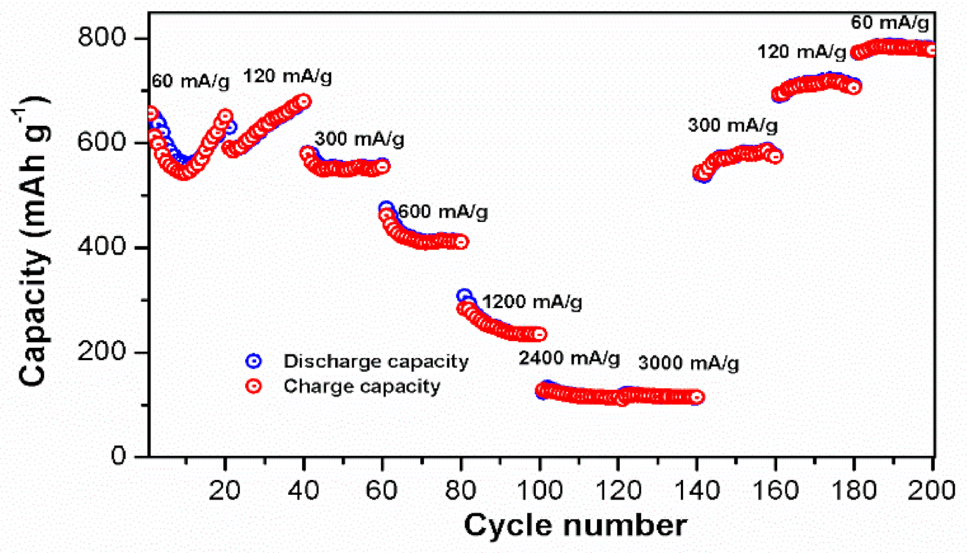
The rate capability of G-NiFum was demonstrated by subjecting the material to galvanostatic cycling at different current densities (discharge and charge at the same current densities) such as 60, 120, 300, 600, 1200, 2400, and 3600 mA g−1, where 1C represents 310 mA g−1 (Figure 4). It was observed that the capacity of G-Fum was decreasing during the initial 10 cycles, and then it increased to 40 cycles. The charge capacities obtained at 60, 120, 300, 600, 1200, and 3600 mA g−1 were 643, 678, 552, 411, 234, and 113 mAh g−1, respectively. When the current rate was decreased, the capacity of the material was found to be higher than that obtained initially. At 300, 120, and 60 mA g−1, the capacities returned to 577, 710, and 780 mAh g−1, respectively.

3.3. Electrochemical Impedance Spectroscopy (EIS)

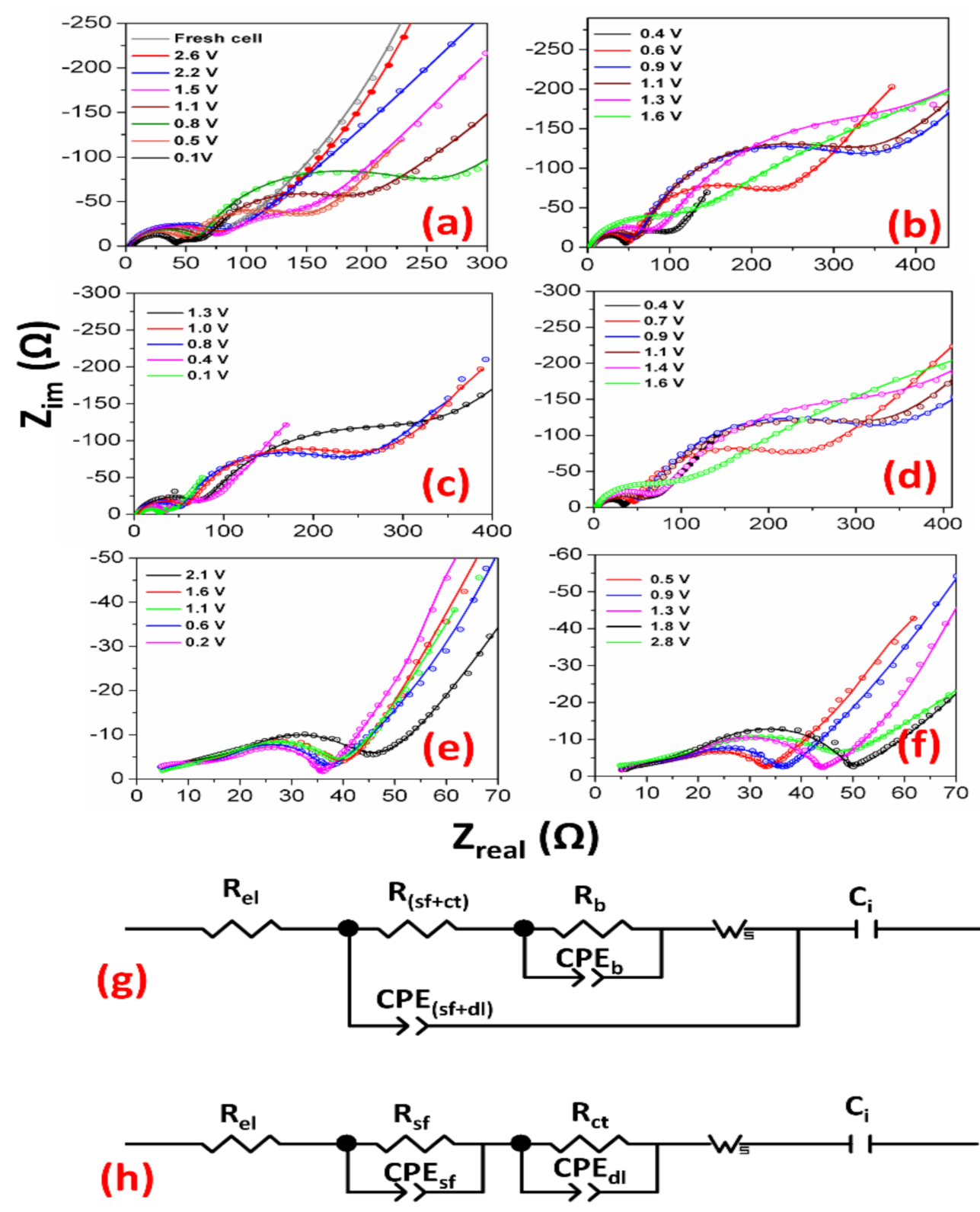
To gain further insight into the electrochemical lithium storage in the material, EIS measurements of G-NiFum were performed at different voltages during 1st, 2nd, and 200th cycles. The cells were subjected to charge and discharge at a constant current density of 200 mA g−1, and they were relaxed in open circuit conditions for 30 min before the data collection. The results are shown as Nyquist plots where the real part of impedance (Zreal) is plotted against the imaginary part of impedance (Zim). Equivalent circuits were constructed with series and parallel combinations of resistors and capacitors (constant phase elements) to understand the mechanism of lithium storage and to evaluate the contribution of individual processes leading to the overall impedance of the cell.
Nyquist plots of G-NiFum for the initial discharge and initial charge cycles are shown in Figure 5a,b, respectively. An equivalent circuit (shown in Figure 5g) consisting of intrinsic resistance (Rel), a combined resistance of surface film and charge transfer resistance (Rsf+ct) and the associated surface-film and double-layer capacitance (CPEsf+dl), bulk resistance (Rb), and the associated capacitance (CPEb), Warburg impedance (Ws), and intercalation capacitance (Ci) was used to fit the experimental data [46]. The angle of distortion for the two semicircles are denoted as α and α’, respectively (Table 1). A fresh cell which was equilibrated for 12 h showed a single semicircle in the high-frequency region of 360 kHz to 5 mHz, indicating that the major contribution is from the surface film resistance. The resistance (Rsf+ct) was calculated to be 66 Ω, and the values are tabulated in Table 2. There was a negligible difference in the intrinsic resistance (~5 Ω) at different voltages. Upon decreasing the voltage, impedance remains almost invariable till 1.5 V (Table 2). The growth of the passivation layer decreases once the cell reaches 1.1 V, as observed from the slight reduction in the impedance. In addition, the initial redox reaction necessitates the conduction of ions between the electrodes, and it involves the initial destruction of the solid−electrolyte interface (SEI). At 1.1 V, there was a second semicircle (Figure 5a) which can be attributed to bulk resistance as it was observed in the low-frequency region. The overall cell impedance was lowest at the completely discharged state as the formation of highly conducting Ni metal upon conversion of nickel fumarate helps in improved conductivity.
During the first charge cycle, two semicircles were obtained similar to the initial discharge process. From Table 2, it can be inferred that the surface film and charge transfer resistance and capacitance are similar to the discharge cycle. However, the contribution from bulk resistance was found to be significantly higher leading to an overall increase in the impedance of the cell. This is also reflected in the galvanostatic cycling studies in which the initial coulombic efficiencies are low. Similar values were observed for the second charge and discharge cycle, as shown in Figure 5c,d. After the cell was subjected to 200 cycles in the galvanostatic process, EIS measurements were carried out. As inferred from Figure 5e,f, the impedance of the cell was considerably lower, indicating improved lithium storage. During the galvanostatic cycling, the capacity was found to increase during cycling which can be supported by the decrease in the impedance. Distinct from the first and second cycles, the bulk resistance was negligible. The different equivalent circuit was necessary to fit the Nyquist plots of 201st cycle, owing to change in the morphology, creation of new lithium storage sites, etc. [46]. Moreover, the surface film and charge transfer kinetics appeared as individual processes, while they were found to overlap during the initial cycle. The individual resistances and capacitances obtained from fitting are provided in Table 3. The capacitance of the cell also increased supporting the fact that the capacitive process partially contributed to the lithium storage in the cell. The fully discharged state has a low impedance of 35 Ω which shows good conductivity of the G-NiFum electrodes.

4. Conclusions

Nickel fumarate tetrahydrate was prepared with a one-dimensional polymeric structure, and a composite of the material with reduced graphene oxide was achieved. The dehydrated materials were tested as novel LIB anode materials. FESEM and TEM characterisations indicated the formation of submicron-sized particles anchored on rGO sheets. The cell prepared with rGO composite (G-NiFum) showed excellent capacity and cycling stability, compared with pristine material. At the end of 60 cycles, a reversible capacity of ~800 mAh g−1 was obtained for the G-NiFum composite.

Author Contributions

S.A.H.—Experimental work, Formal analysis, Writing—original draft. M.V.R.—supervision, Formal analysis, Writing—review & editing, Z.K.—Writing—review & editing, N.S.H. & S.Y.A.-Q.—funding acquisition to S.A.H., S.P.—experimental work and analysis Writing. All authors have read and agreed to the published version of the manuscript.

Funding

No external funding.

Institutional Review Board Statement

Not applicable.

Informed Consent Statement

Not applicable.

Data Availability Statement

Not applicable.

Acknowledgments

Authors (Nusyba S. Hassan and Siham Y. Al-Qaradawi) thanks NPRP 7-302-2-126 from the Qatar National Research Fund (a member of the Qatar Foundation). Authors thank V. Harini River School Board, Quebec, Canada for her help with English corrections and editing. M V R thank to David Murray, Vice president, Hydro Quebec for his support and encouragement.

Conflicts of Interest

The authors declare no conflict of interest.

References

  1. Choi, N.-S.; Chen, Z.; Freunberger, S.A.; Ji, X.; Sun, Y.-K.; Amine, K.; Yushin, G.; Nazar, L.F.; Cho, J.; Bruce, P.G. Challenges Facing Lithium Batteries and Electrical Double-Layer Capacitors. Angew. Chem. Int. Ed. 2012, 51, 9994–10024. [Google Scholar] [CrossRef] [PubMed]
  2. Goriparti, S.; Miele, E.; De Angelis, F.; Di Fabrizio, E.; Zaccaria, R.P.; Capiglia, C. Review on recent progress of nanostructured anode materials for Li-ion batteries. J. Power Sources 2014, 257, 421–443. [Google Scholar] [CrossRef] [Green Version]
  3. Reddy, M.V.; Subba Rao, G.V.; Chowdari, B.V.R. Metal Oxides and Oxysalts as Anode Materials for Li Ion Batteries. Chem. Rev. 2013, 113, 5364–5457. [Google Scholar] [PubMed]
  4. Obrovac, M.N.; Chevrier, V.L. Alloy Negative Electrodes for Li-Ion Batteries. Chem. Rev. 2014, 114, 11444–11502. [Google Scholar] [CrossRef]
  5. Li, J.-Y.; Xu, Q.; Li, G.; Yin, Y.-X.; Wan, L.-J.; Guo, Y.-G. Research progress regarding Si-based anode materials towards practical application in high energy density Li-ion batteries. Mater. Chem. Front. 2017, 1, 1691–1708. [Google Scholar] [CrossRef]
  6. Chan, C.K.; Peng, H.; Liu, G.; McIlwrath, K.; Zhang, X.F.; Huggins, R.A.; Cui, Y. High-performance lithium battery anodes using silicon nanowires. Nat. Nanotechnol. 2008, 3, 31–35. [Google Scholar] [CrossRef] [PubMed]
  7. Hu, X.; Zeng, G.; Chen, J.; Lu, C.; Wen, Z. 3D graphene network encapsulating SnO2 hollow spheres as a high-performance anode material for lithium-ion batteries. J. Mater. Chem. A 2017, 5, 4535–4542. [Google Scholar] [CrossRef]
  8. Chan, C.K.; Zhang, X.F.; Cui, Y. High Capacity Li Ion Battery Anodes Using Ge Nanowires. Nano Lett. 2008, 8, 307–309. [Google Scholar] [CrossRef]
  9. Scrosati, B.; Garche, J. Lithium batteries: Status, prospects, and future. J. Power Sources 2010, 195, 2419–2430. [Google Scholar] [CrossRef]
  10. Su, X.; Wu, Q.; Li, J.; Xiao, X.; Lott, A.; Lu, W.; Sheldon, B.W.; Wu, J. Silicon-Based Nanomaterials for Lithium-Ion Batteries: A Review. Adv. Energy Mater. 2014, 4, 1300882. [Google Scholar] [CrossRef]
  11. Reddy, M.V.; Yu, T.; Sow, C.-H.; Shen, Z.X.; Lim, C.T.; Subba Rao, G.V.; Chowdari, B.V.R. α-Fe2O3 nanoflakes as an anode material for Li-ion batteries. Adv. Funct. Mater. 2007, 17, 2792–2799. [Google Scholar] [CrossRef]
  12. Han, C.-G.; Zhu, C.; Sheng, N.; Aoki, Y.; Habazaki, H.; Akiyama, T. A facile one-pot synthesis of FeOx/carbon/graphene composites as superior anode materials for lithium-ion batteries. Electrochim. Acta 2017, 235, 88–97. [Google Scholar] [CrossRef]
  13. Jiao, F.; Bruce, P.G. Mesoporous crystalline β-MnO2—A reversible positive electrode for rechargeable lithium batteries. Adv. Mater. 2007, 19, 657–660. [Google Scholar] [CrossRef]
  14. Lu, B.; Liu, J.; Hu, R.; Wang, H.; Liu, J.; Zhu, M. Facile synthesis of self-supported Mn3O4@C nanotube arrays constituting an ultrastable and high-rate anode for flexible Li-ion batteries. J. Mater. Chem. A 2017, 5, 8555–8565. [Google Scholar] [CrossRef]
  15. Hameed, A.S.; Reddy, M.V.; Chowdari, B.V.R.; Vittal, J.J. Preparation of rGO-wrapped magnetite nanocomposites and their energy storage properties. RSC Adv. 2014, 4, 64142–64150. [Google Scholar] [CrossRef]
  16. Li, L.; Cheah, Y.; Ko, Y.; Teh, P.; Wee, G.; Wong, C.; Peng, S.; Srinivasan, M. The facile synthesis of hierarchical porous flower-like NiCo2O4 with superior lithium storage properties. J. Mater. Chem. A 2013, 1, 10935–10941. [Google Scholar] [CrossRef]
  17. Hameed, A.S.; Bahiraei, H.; Reddy, M.V.; Shoushtari, M.Z.; Vittal, J.J.; Ong, C.K.; Chowdari, B.V.R. Lithium Storage Properties of Pristine and (Mg, Cu) Codoped ZnFe2O4 Nanoparticles. ACS Appl. Mater. Interfaces 2014, 6, 10744–10753. [Google Scholar] [CrossRef] [PubMed]
  18. Cabana, J.; Monconduit, L.; Larcher, D.; Palacin, M.R. Beyond Intercalation-Based Li-Ion Batteries: The State of the Art and Challenges of Electrode Materials Reacting through Conversion Reactions. Adv. Mater. 2010, 22, E170–E192. [Google Scholar] [CrossRef] [PubMed]
  19. Kucinskis, G.; Bajars, G.; Kleperis, J. Graphene in lithium ion battery cathode materials: A review. J. Power Sources 2013, 240, 66–79. [Google Scholar] [CrossRef]
  20. Xin, S.; Guo, Y.-G.; Wan, L.-J. Nanocarbon Networks for Advanced Rechargeable Lithium Batteries. Acc. Chem. Res. 2012, 45, 1759–1769. [Google Scholar] [CrossRef]
  21. Wu, Z.-S.; Zhou, G.; Yin, L.-C.; Ren, W.; Li, F.; Cheng, H.-M. Graphene/metal oxide composite electrode materials for energy storage. Nano Energy 2012, 1, 107–131. [Google Scholar] [CrossRef]
  22. Inagaki, M. Carbon coating for enhancing the functionalities of materials. Carbon 2012, 50, 3247–3266. [Google Scholar] [CrossRef]
  23. Fedele, L.; Sauvage, F.; Gottis, S.; Davoisne, C.; Salager, E.; Chotard, J.-N.; Becuwe, M. 2D-Layered Lithium Carboxylate Based on Biphenyl Core as Negative Electrode for Organic Lithium-Ion Batteries. Chem. Mater. 2017, 29, 546–554. [Google Scholar] [CrossRef]
  24. Liang, Y.; Tao, Z.; Chen, J. Organic electrode materials for rechargeable lithium batteries. Adv. Energy Mater. 2012, 2, 742–769. [Google Scholar] [CrossRef]
  25. Walker, W.; Grugeon, S.; Mentre, O.; Laruelle, S.; Tarascon, J.-M.; Wudl, F. Ethoxycarbonyl-Based Organic Electrode for Li-Batteries. J. Am. Chem. Soc. 2010, 132, 6517–6523. [Google Scholar] [CrossRef] [PubMed]
  26. Wang, S.; Wang, L.; Zhang, K.; Zhu, Z.; Tao, Z.; Chen, J. Organic Li4C8H2O6 Nanosheets for Lithium-Ion Batteries. Nano Lett. 2013, 13, 4404–4409. [Google Scholar] [CrossRef] [PubMed]
  27. He, S.; Li, Z.; Ma, L.; Wang, J.; Yang, S. Graphene oxide-templated growth of MOFs with enhanced lithium-storage properties. New J. Chem. 2017, 41, 14209–14216. [Google Scholar] [CrossRef]
  28. He, S.; Zhou, X.; Li, Z.; Wang, J.; Ma, L.; Yang, S. Fluorine Doping Strengthens the Lithium-Storage Properties of the Mn-Based Metal-Organic Framework. ACS Appl. Mater. Interfaces 2017, 9, 26907–26914. [Google Scholar] [CrossRef]
  29. Li, X.; Cheng, F.; Zhang, S.; Chen, J. Shape-controlled synthesis and lithium-storage study of metal-organic frameworks Zn4O(1,3,5-benzenetribenzoate)2. J. Power Sources 2006, 160, 542–547. [Google Scholar] [CrossRef]
  30. Thakur, A.K.; Majumder, M.; Patole, S.P.; Zaghib, K.; Reddy, M.V. Metal–organic framework-based materials: Advances, exploits, and challenges in promoting post Li-ion battery technologies. Mater. Adv. 2021, 2, 2457–2482. [Google Scholar] [CrossRef]
  31. Wang, L.; Han, Y.; Feng, X.; Zhou, J.; Qi, P.; Wang, B. Metal-organic frameworks for energy storage: Batteries and supercapacitors. Coord. Chem. Rev. 2016, 307, 361–381. [Google Scholar] [CrossRef]
  32. Long, J.R.; Yaghi, O.M. The pervasive chemistry of metal-organic frameworks. Chem. Soc. Rev. 2009, 38, 1213–1214. [Google Scholar] [CrossRef] [PubMed]
  33. Férey, G.; Millange, F.; Morcrette, M.; Serre, C.; Doublet, M.-L.; Grenèche, J.-M.; Tarascon, J.-M. Mixed-Valence Li/Fe-Based Metal–Organic Frameworks with Both Reversible Redox and Sorption Properties. Angew. Chem. Int. Ed. 2007, 46, 3259–3263. [Google Scholar] [CrossRef]
  34. Maiti, S.; Pramanik, A.; Manju, U.; Mahanty, S. Reversible Lithium Storage in Manganese 1,3,5-Benzenetricarboxylate Metal–Organic Framework with High Capacity and Rate Performance. ACS Appl. Mater. Interfaces 2015, 7, 16357–16363. [Google Scholar] [CrossRef]
  35. Maiti, S.; Pramanik, A.; Unnikrishnan, M.; Mahanty, S. Cu3(1,3,5-benzenetricarboxylate)2 Metal-Organic Framework: A Promising Anode Material for Lithium-ion Battery. J. Microporous Mesoporous Mater. 2016, 226, 353–359. [Google Scholar] [CrossRef]
  36. Hu, H.; Lou, X.; Li, C.; Hu, X.; Li, T.; Chen, Q.; Shen, M.; Hu, B. A thermally activated manganese 1,4-benzenedicarboxylate metal organic framework with high anodic capability for Li-ion batteries. New J. Chem. 2016, 40, 9746–9752. [Google Scholar] [CrossRef]
  37. Saravanan, K.; Nagarathinam, M.; Balaya, P.; Vittal, J.J. Lithium storage in a metal organic framework with diamondoid topology—A case study on metal formats. J. Mater. Chem. 2010, 20, 8329–8335. [Google Scholar] [CrossRef]
  38. Gou, L.; Liu, P.-G.; Liu, D.; Wang, C.-Y.; Lei, H.-Y.; Li, Z.-Y.; Fan, X.-Y.; Li, D.-L. Rational synthesis of Ni3(HCOO)6/CNT ellipsoids with enhanced lithium storage performance: Inspired by the time evolution of the growth process of a nickel formate framework. Dalton Trans. 2017, 46, 6473–6482. [Google Scholar] [CrossRef]
  39. Oh, H.-J.; Jo, C.-H.; Yoon, C.S.; Yashiro, H.; Kim, S.-J.; Passerini, S.; Sun, Y.-K.; Myung, S.-T. Nickel oxalate dihydrate nanorods attached to reduced graphene oxide sheets as a high-capacity anode for rechargeable lithium batteries. NPG Asia Mater. 2016, 8, e270. [Google Scholar] [CrossRef] [Green Version]
  40. López, M.C.; Tirado, J.L.; Pérez Vicente, C. Structural and comparative electrochemical study of M(II) oxalates, M = Mn, Fe, Co, Ni, Cu, Zn. J. Power Sources 2013, 227, 65–71. [Google Scholar] [CrossRef]
  41. Park, J.-S.; Jo, J.-H.; Yashiro, H.; Kim, S.-S.; Kim, S.-J.; Sun, Y.-K.; Myung, S.-T. Synthesis and Electrochemical Reaction of Tin Oxalate-Reduced Graphene Oxide Composite Anode for Rechargeable Lithium Batteries. ACS Appl. Mater. Interfaces 2017, 9, 25941–25951. [Google Scholar] [CrossRef] [PubMed]
  42. Wang, Y.; Qu, Q.; Liu, G.; Battaglia, V.S.; Zheng, H. Aluminum fumarate-based metal organic frameworks with tremella-like structure as ultrafast and stable anode for lithium-ion batteries. Nano Energy 2017, 39, 200–210. [Google Scholar] [CrossRef]
  43. Hummers, W.S.; Offeman, R.E. Preparation of Graphitic Oxide. J. Am. Chem. Soc. 1958, 80, 1339. [Google Scholar] [CrossRef]
  44. Yaghtin, A.; Masoudpanah, S.M.; Hasheminiasari, M.; Salehi, A.; Safanama, D.; Ong, C.K.; Adams, S.; Reddy, M.V. Effect of Reducing Agent on Solution Synthesis of Li3V2(PO4)3 Cathode Material for Lithium Ion Batteries. Molecules 2020, 25, 3746. [Google Scholar] [CrossRef] [PubMed]
  45. Xie, H.Z.; Zheng, Y.Q.; Wu, Q.S. Crystal structure of tetraaquafumaratonickel(II), Ni(H2O)4(C4H2O4). Z. Krist. New Cryst. Struct. 2003, 218, 111–112. [Google Scholar]
  46. Petnikota, S.; Marka, S.K.; Banerjee, A.; Reddy, M.V.; Srikanth, V.V.S.S.; Chowdari, B.V.R. Graphenothermal reduction synthesis of ‘exfoliated graphene oxide/iron (II) oxide’ composite for anode application in lithium ion batteries. J. Power Sources 2015, 293, 253–263. [Google Scholar] [CrossRef]
  47. Hameed, A.S.; Reddy, M.V.; Nagarathinam, M.; Runčevski, T.; Dinnebier, R.E.; Adams, S.; Chowdari, B.; Vittal, J.J. Room temperature large-scale synthesis of layered frameworks as low-cost 4 V cathode materials for lithium ion batteries. Sci. Rep. 2015, 5, 16270. [Google Scholar] [CrossRef] [Green Version]
  48. Petnikota, S.; Maseed, H.; Srikanth, V.V.S.S.; Reddy, M.V.; Adams, S.; Srinivasan, M.; Chowdari, B.V.R. Experimental Elucidation of a Graphenothermal Reduction Mechanism of Fe2O3: An Enhanced Anodic Behavior of an Exfoliated Reduced Graphene Oxide/Fe3O4 Composite in Li-Ion Batteries. J. Phys. Chem. C 2017, 121, 3778–3789. [Google Scholar] [CrossRef]
  49. Aragón, M.J.; León, B.; Pérez Vicente, C.; Tirado, J.L. Synthesis and Electrochemical Reaction with Lithium of Mesoporous Iron Oxalate Nanoribbons. Inorg. Chem. 2008, 47, 10366–10371. [Google Scholar] [CrossRef]
  50. Ang, W.A.; Gupta, N.; Prasanth, R.; Madhavi, S. High-Performing Mesoporous Iron Oxalate Anodes for Lithium-Ion Batteries. ACS Appl. Mater. Interfaces 2012, 4, 7011–7019. [Google Scholar] [CrossRef] [PubMed]
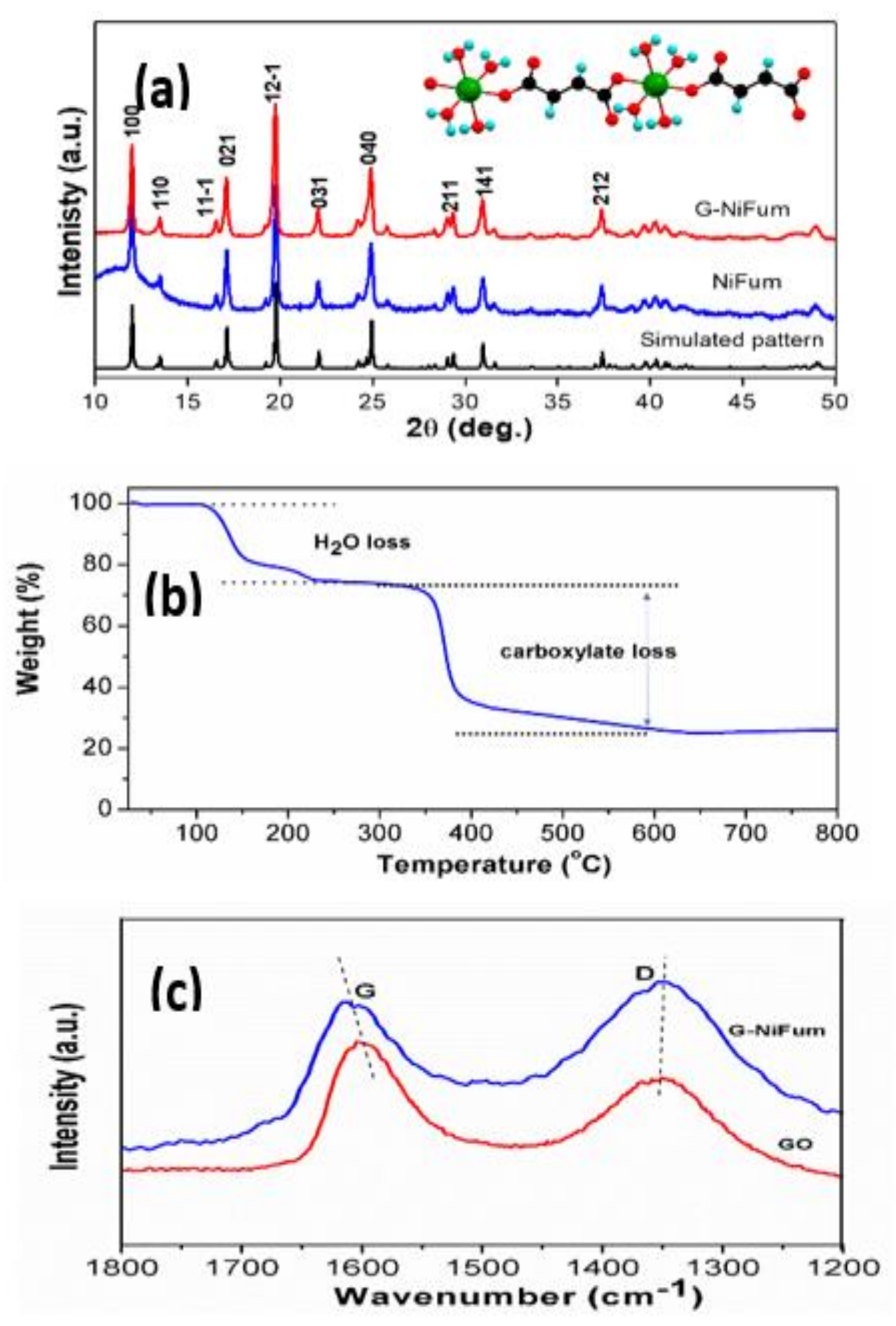
Figure 1. (a) Powder X-ray diffraction patterns of NiFum and G-NiFum compared with its simulated pattern. Crystallographic representation of the one-dimensional polymeric structure of Ni(C4H2O4)(H2O)4. is shown in the inset of Figure 1a. The green, black-, red-, and blue-coloured balls represent nickel, carbon, oxygen, and hydrogen atoms, respectively; (b) thermogravimetric profiles of NiFum in a nitrogen atmosphere at 5 °C min−1; (c) comparison of Raman spectra of G-NiFum with that of graphene oxide (GO). The reduction of GO during the synthesis is demonstrated by the increase in the ID/IG ratio.
Electrochem 02 00029 g001
Figure 2. (a,b) SEM micrographs of NiFum at magnifications of 5000 and 30,000, respectively; (c,d) SEM micrographs of G-NiFum at magnifications of 5000 and 30,000, respectively; (e,f) TEM images of NiFum and G-NiFum, respectively.
Electrochem 02 00029 g002
Figure 3. (a) Galvanostatic charge–discharge curves of G-NiFum for selected cycles at a current density of 60 mA g−1 in the potential window of 0.005–3.0 V. The formation step is shown in red; (b) comparison of charge–discharge profiles of NiFum and G-NiFum for the third cycle; (c) capacity vs. cycle number plots of NiFum and G-NiFum.
Electrochem 02 00029 g003
Figure 4. Rate capability studies of G-Nifum composite at different current densities such as 60, 120, 300, 600, 1200, 2400, and 3600 mA g−1.
Electrochem 02 00029 g004
Figure 5. EIS spectra (Nyquist plots) of G-NiFum at various voltages during (a) 1st discharge cycle, (b) 1st charge cycle, (c) 2nd discharge cycle, (d) 2nd charge cycle, (e) 200th discharge cycle, (f) 201st charge cycle, and (g,h) equivalent circuits used for fitting the experimental Nyquist plots.
Electrochem 02 00029 g005
Table 1. Comparison of capacities obtained for 1st, 2nd, and 60th cycles of NiFum and G-NiFum at a current density of 60 mA g−1.
Cycle NoNiFumG-NiFum
Charge Capacity (mAh g−1)Discharge Capacity (mAh g−1)Coulombic Efficiency (%)Charge Capacity (mAh g−1)Discharge Capacity (mAh g−1)Coulombic Efficiency (%)
1st cycle620106658658132050
2nd cycle5876279461165793
50th cycle4854919979780599
Table 2. EIS fitting results of G-NiFum at different voltages for the first cycle.
VoltageR(sf+ct) (Ω)CPE(sf+dl) (μF)αRb (Ω)CPEb (mF)α’Ci (F)
First discharge cycle
Fresh cell66370.67---0.01
2.6 V72330.68---0.01
2.2 V84460.64---0.06
1.5 V70510.64---0.12
1.1 V63400.70971.90.890.09
0.8 V57380.731741.90.830.08
0.5 V48360.76833.50.830.11
0.1 V38630.7215140.770.14
First charge cycle
0.4 V43430.75445.60.820.23
0.6 V47360.771432.60.870.19
0.9 V53360.752241.80.870.36
1.1 V59530.702281.60.880.28
1.3 V73480.712401.90.620.29
1.6 V127710.633601.90.550.78
Table 3. EIS fitting results of G-NiFum at different voltages for the 201st cycle.
VoltageRsf (Ω)CPEsf (μF)αRct (Ω)CPEdl (μF)α’Ci (F)
201st discharge cycle
2.1 V421910.28121520.910.85
1.6 V311600.30121900.870.47
1.1 V215120.40141800.870.52
0.6 V213430.42141620.860.45
0.2 V201220.36122000.870.20
201st charge cycle
0.5 V214100.4324690.911.51
0.9 V194230.4620940.880.75
1.3 V194090.43141470.860.68
1.8 V163810.47131800.840.46
2.8 V278120.36191820.810.21
Publisher’s Note: MDPI stays neutral with regard to jurisdictional claims in published maps and institutional affiliations.