Abstract
This work presents a contribution to the study of a new Ni-rich spinel cathode material, LiNiMnO4, for Li-ion batteries operating in the 5-V region. The LiNiMnO4 compound was synthesized by a sol-gel method assisted by ethylene diamine tetra-acetic acid (EDTA) as a chelator. Structural analyses carried out by Rietveld refinements and Raman spectroscopy, selected area electron diffraction (SAED) and X-ray photoelectron (XPS) spectroscopy reveal that the product is a composite (LNM@NMO), including non-stoichiometric LiNiMnO4-δ spinel and a secondary Ni6MnO8 cubic phase. Cyclic voltammetry and galvanostatic charge-discharge profiles show similar features to those of LiNi0.5Mn1.5O4 bare. A comparison of the electrochemical performances of 4-V spinel LiMn2O4 and 5-V spinel LiNi0.5Mn1.5O4 with those of LNM@NMO composite demonstrates the long-term cycling stability of this new Ni-rich spinel cathode. Due to the presence of the secondary phase, the LNM@NMO electrode exhibits an initial specific capacity as low as 57 mAh g−1 but shows an excellent electrochemical stability at 1C rate for 1000 cycles with a capacity decay of 2.7 × 10⁻³ mAh g−1 per cycle.
1. Introduction
Major efforts have been made to develop Li-ion batteries (LIBs) in order to provide clean and friendly transportation to the environment, such as plug-in hybrid electric vehicles (PHEVs) and pure electric vehicles (EVs) [1,2,3]. For large-scale applications, the electrochemical rechargeable cells must offer high performance such as high energy density, good structural stability upon cycling, high-rate capability and sufficient safety. In this context, the positive electrode (cathode) materials have to satisfy and maintain the above requirements [4,5]. The standard LiCoO2 (LCO) cathode material (costly and toxic) should be replaced by inexpensive and environment friendly compounds. Among the reported cathodes, spinel LiMn2O4 (LMO) is considered as one of the most attractive materials for LIBs due to its low toxicity, good thermal stability, low production cost and abundant manganese resources [6]. This electrode material operating at ca. 4 V vs. Li+/Li is a three-dimensional (3D) Li-insertion framework providing 3D channels for high-rate Li+ conduction and delivering a theoretical specific capacity of 148 mAh g−1, which makes its energy density comparable with that of the LCO electrode-prototype [7]. Although safer than LCO (due to the energetic position of the redox couple Mn3+/Mn4+), LMO suffers from capacity fading with long cycling, which limits its practical usage [8]. This decay in capacity is associated with the Mn3+ dissolution in the acidic electrolyte [9] and with the structural instability due to Jahn–Teller (JT) distortion of high-spin Mn3+ at deep state of discharge (SOD) [10].
The drawbacks of spinel LMO can be overcome by different methods, including doping/partial substitution of the Mn3+ JT ions, control of the particle morphology, the coating on the surface of particle with metal oxides (Al2O3, TiO2, ZrO2) or lithiated compounds (Li2TiO3, Li3PO4) [11]. A variety of M-dopant (M = Cr, Ni, Co, Ti, Mg, Al, etc.) has been shown to stabilize the LMO spinel framework due to the formation of the stronger Ni-O bonds than Mn-O [12,13,14,15]. Thus, doped-LMO compounds are able to operate at high voltage (>4.7 V vs. Li+/Li) [16]. In this regard, LiNiyMn2-yO4 cathode materials (i.e., called as 5-V spinel electrode) have been intensively investigated. Among them, LiNi0.5Mn1.5O4 (LNM) is of particular interest given its theoretical specific capacity (147 mAh g−1), high energy density (>650 Wh kg−1), good cycling performance and good rate capability. Unlike LMO, the electrochemical features of LNM is due to the presence of Ni cations in the oxidation state +2, while Mn ions remain in the +4 state in the ideal spinel lattice [17,18,19,20,21,22,23,24,25,26,27,28,29,30,31,32,33,34,35,36,37,38,39,40,41,42,43,44,45,46,47,48,49,50,51,52,53,54,55,56,57,58,59,60,61,62,63,64,65,66,67,68,69,70,71,72,73,74,75,76,77]. Moreover, Mn4+ ion of LNM lowers the Ni3+/Ni2+ couple to 4.7 V and the top of the O-2p bands to 4.8 V vs. Li+/Li; both features provide a high-operating voltage cathode. Moreover, the electrochemical activity takes place as Ni2+/Ni3+ and Ni3+/Ni4+ redox couples with no significant voltage step between them, including the transfer of 1e- for the fully delithiated LNM electrode.
The electrochemical response of LNM cathode materials synthesized with some impurities has been reported by several papers [47,68,73,74]. Wang et coworkers [47] showed that the presence of LixNi1−xO results in a slight increase of the difference between anodic and cathodic peak potentials, as well as a loss of specific discharge capacity of ~15 mAh g−1 upon 100 cycles. Börner et al. [73] demonstrated the severe impact of a small amount of an inactive LixNi1−xO rock-salt phase on the electrochemical performance. The initial discharge capacity of 38 mAh g−1 was maintained on 250 cycles at 0.1C rate. Liu et al. [68] investigated the effect of the impurity LixNi1−xO on the electrochemical performance of LNM electrodes. A comparison of material containing 1.6 and 8.5 wt.% Li0.26Ni0.72O shows that a specific capacity of 100 mAh g−1 can be delivered at 4C rate. The authors concluded that the secondary phase reduces the specific capacity but does not adversely affect the cycle performance of the electrode. The same trend was observed by Yoon et al. [74]. The fast-cooled sample (5 °C min−1) exhibits higher quantity of LixNi1−xO impurities than that of the slow-cooled (0.5 °C min−1) material but exhibits higher discharge capacity after 100 cycles (110 vs. 85 mAh g−1). Lee et al. [65] reported that the cyclability of LNM tested at 0.4 mA cm−2 between 5.2 and 3.5 V is not affected by impurities of nickel oxide except the occurrence of a small 4.1 V plateau (12 mAh g−1 wide). The quantitative analysis of the composition of LNM powders synthesized by the hydrothermal method using different ratios of H2O/ethylene glycol solvent shows the presence of 2.07–3.60% Ni6MnO8 as impurity phase [31]. Even with 2.7% Ni6MnO8, the LNM electrode delivers a specific capacity of 129 mAh g−1 at 0.2C rate and, among all samples, exhibits a low value of charge transfer resistance (Rct), which makes the smallest electrochemical polarization and highest electrochemical reactivity. It seems that increasing the oxygen non-stoichiometry can also improve the rate capability of LiNi0.5Mn1.5O4+δ electrode. Jin et al. [75] reported that the disordered structure (Fdm) and increased Mn3+ content when δ increases from 0.015 to 0.033 result in 47% increase in discharge capacity.
In this study, we aim to fundamentally understand the effect of increasing Ni content on the structure, morphology, electrical and electrochemical properties of spinel LiNiyMn2−yO4 with y = 1. To the best of our knowledge, this is the first attempt to investigate the Ni-rich spinel-type LiNiMnO4. This compound was formed with a large amount of Ni impurities, which form an efficient composite electrode. The effect of the Ni6MnO8 impurity is investigated and the LiNiMnO4@Ni6MnO8 composite is used as a 5-volt cathode material for LIBs. A comparison with its parents (i.e., the 4-V spinel LMO and the 5-V spinel LNM) confirms the long-term cycling stability of this new Ni-rich spinel cathode. These materials are prepared by a sol-gel method assisted by ethylene diamine tetra-acetic acid (EDTA) as a chelating agent and characterized by X-ray diffraction (XRD), high-resolution transmission electron microscopy (HRTEM), selected area electron diffraction (SAED), X-ray photoemission spectroscopy (XPS) and Raman scattering (RS) spectroscopy. Electrochemical performances are examined using cyclic voltammetry (CV) and galvanostatic charge-discharge (GCD) tests. Electrochemical impedance spectroscopy (EIS) and area-specific impedance (ASI) evidence the Li ions kinetics and the change in the overall cell potential with the depth-of-discharge (DOD) of each electrode.
2. Materials and Methods
2.1. Preparation of LiNiyMn1−yO4 Samples
LiNiyMn1−yO4 (y = 0.0, 0.5 and 1.0) powders were synthesized by a sol-gel method using ethylenediaminetetraacetic acid (EDTA) as a chelating agent. This preparation route was described in previous work [20]. Li, Mn and Ni acetates (99.99% grade, Merck KGaA, Darmstadt, Germany) were used as starting materials. According to the desired stoichiometry, proper amounts of these starting materials were dissolved in de-ionized water to form an aqueous solution of 0.165 mol of lithium acetate and 0.33 mol of nickel and manganese acetate, (where Ni:Mn ratio = 0.0:2.0, 0.5:1.5 and 1.0:1.0 for y = 0.0, 0.5 and 1.0 respectively). The dissolved solutions were added stepwise into a stirred aqueous solution of EDTA with a 1:1 metal:chelator ratio. The solution was stirred for 3 h to form a homogenous mixture of the reaction reagents and favor complex reaction between metal ions and EDTA. Ammonium hydroxide was added to adjust the pH of the solution at ~7. The transparent gel was formed after slow evaporation of the solution. The resulting precursor was heated and decomposed at 450 °C for 5 h in the air to eliminate the organic substances and convert the metal carboxylate to oxides, then cooled to room temperature. Finally, the decomposed powders were slightly ground using a mortar and recalcined at 600 °C for 12 h at heating rate of 5 °C min−1 in air. A schematic representation of the spinel growth process is shown in Figure S1 in Supporting Information.
2.2. Material Characterization
The crystalline structure and phase identification were investigated by X-ray diffraction using Philips X’Pert apparatus equipped with a CuKα radiation source (λ = 1.54056 Å). The diffractograms were recorded at room temperature in the 2θ-range 10–80° at a scanning rate of 0.02° min−1. The obtained XRD patterns were refined using the FULLPROF software (Toolbar Fullprof suit program (3.00), version June-2015) [21]. The morphology of the specimens was investigated using a JEOL transmission electron microscope (TEM, JEOL model JEM-2100, Tokyo, Japan) including a SAED mode. Elemental composition was analyzed by X-ray photoelectron spectroscopy using an ESCALAB 250Xi apparatus (Thermo Fisher Scientific, Les Ulis, France) equipped with a Mg Kα source (λ = 1253.6 eV). BET surface area and pore size distribution of synthesized samples were determined from N2-adsorption experiments using (Belsorp max version 2.3.2). Raman spectra were collected with a micro-Raman spectrometer (model inVia, Renishaw Inc. West Dundee, IL, USA) using the laser excitation wavelength λ = 532 nm. Low laser power (0.5%, 0.25 mW) was utilized to preserve the sample surface. A silicon crystal was used as a reference for the wavenumber calibration regularly verified with the phonon peak at 520 cm−1.
Electrochemical cells were configured as CR2032-type coin cells with lithium metal foil as the counter electrode, Celgard 2400 as separator and 1 mol L−1 LiPF6 in ethylene carbonate:diethyl carbonate (EC:DEC, 1:1 in volume) as the electrolyte (see Figure S2 in Supporting Information). The positive electrode composite was fabricated using a 50:30:20 (weight%) mixture of active material, carbon black and polyvinylidene difluoride (PVdF). The mixture was added into the NMP solution and mixed homogeneously for 12 h. The produced slurries were coated onto a thin Al foil and dried at 100 °C in a vacuum oven for 12 h. The size of the electrode disc is 12 mm in diameter with a mass loading of 1.5 mg cm−2. Based on the SEM images (Figure S3 in Supporting Information), we could barely find any morphological differences between the LiNiyMn2−yO4 materials. The cyclic voltammograms (CV) were recorded at a sweep rate of 0.02 mV s−1 in the voltage range between 3.5 and 4.9 V. Galvanostatic charge-discharge tests were performed at 1C-rate (full charge in 1 h, 1C = 148 mA g−1) using a battery cycler Arbin Instruments (model BT-2043 with 20 channels) between 3.5 and 4.9 V at room temperature. EIS experiments were carried out in the frequency range from 0.1 to 500 kHz using a Biologic workstation (model VSP with 3 channels). A sinusoidal signal of amplitude 5 mV was applied and data were the average of two measurements per frequency.
3. Results and Discussion
3.1. Structure and Morphology
The phase identification was performed by XRD, SAED (long-range order) and Raman spectroscopy (local environment), whereas the morphology was investigated using SEM and HRTEM imaging. Figure 1a represents the typical XRD diagram of the as-synthesized Ni-rich LiNiMnO4 spinel powders, along with those of its parents LiNi0.5Mn1.5O4 and LiMn2O4. The XRD patterns of parent LMO and LNM powders can be indexed to the single phase of the spinel cubic structure (Fdm space group); they match well with standard data (i.e., JCPDS card No. 88-1749 for LMO and No. 80-2162 for LNM). Note that, with disordered Ni2+ and Mn4+ on the octahedral sites, Fdm LNM powders crystallize as a non-stoichiometric face-centered cubic phase, which contains trace amounts of Mn3+ ions generated by the loss of oxygen during synthesis, while the ordering of Ni2+ and Mn4+ gives the P4332 structure. Although Fdm disordered and P4332 ordered phases of LNM show similar XRD patterns, we opt for the former based on the analyses from Raman spectroscopy and cyclic voltammetry, as described below.
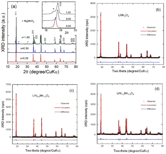
Figure 1.
(a) XRD patterns of the as-prepared LiNiyMn2−yO4 (y = 0.0, 0.5 and 1.0) spinel samples. The insert shows the reflections at ca. 2θ = 18.8°. Stars (*) indicate reflections of Ni6MnO8 impurity. (b) Rietveld refinement of Ni-rich LiNiMnO4. (c) Rietveld refinement of the 4-V spinel LiMn2O4. (d) Rietveld refinement of the 5-V LiNi0.5Mn1.5O4. Cross marks are experimental data and solid lines (in red) are calculated diagrams. The curve at the bottom (in blue) is the difference between the calculated and observed intensities.
The XRD spectrum of LiNiMnO4 displays narrow and sharp diffraction peaks indicating high crystallinity, which can be indexed using the cubic structure of spinel framework with Fdm space group. The predominant reflection at 2θ angle of ca. 18.81° with dhkl of 0.471 nm is ascribed to the (111) planes along with diffraction peaks of lower intensity at 36.50°, 38.17°, 44.34°; 48.55°, 58.69°, 64.53°, 76.17° and 77.45° corresponding to the crystal planes of (311), (222), (400), (311), (511), (440), (531), (533) and (622), with dhkl of 0.245, 0.236, 0.204, 0.187, 0.157, 0.144, 0.126, and 0.123 nm, respectively. Note that, at high 2θ angles, the pair of (533)/(622) reflections is well resolved. Besides the XRD patterns of the spinel phase, extra reflections at 2θ = 18.52°, 21.45°, 30.49°, 37.57°, 43.65° and 67.86° can be ascribed to the XRD patterns of a secondary cubic phase such as LixNi1−xO and/or Ni6MnO8. Therefore, the Ni-rich sample shows the same pattern as the parent compounds with the most intense peaks (111), (311) and (400) characteristic of the spinel phase. This means that Li ions occupy the tetrahedral 8a Wyckoff sites and Mn cations are distributed at octahedral 16d sites, oxygen anions being located at the 32e sites [22]. The ideal cation distribution in Ni-substituted Li-Mn spinel oxide is [Li+]8a[Ni2+0.5Mn4+1.5]16dO4 [23]. By zooming into the 2θ region around 18° (inset of Figure 1a), the slight shift of the Bragg peak of the (111) plane, toward the higher 2θ angle side, is evidenced by an increase in the amount of Ni introduced into the spinel framework. The diffraction peaks noticeably shift to higher angles and the cubic lattice parameter decreases with the large substitution of Ni2+ for Mn3+. With the presence of Ni2+ in the substituted LiMn2O4 phase, the crystal structure is shrunken for two reasons: (i) The Ni-O bond is stronger (1029 kJ·mol−1) than the Mn-O bond (946 kJ·mol−1) and the replacement of Ni for Mn decreases the average atomic distance [24]; and (ii) the partial substitution of Ni2+ for Mn3+ can increase the content of Mn4+ to keep the charge balance, which induces a reduced elementary cell volume because the ionic radius of Mn4+ (r(Mn4+) = 0.53 Å) is smaller than that of Mn3+ (r(Mn3+) = 0.58 Å) [25].
The full structural identification of as-prepared samples was performed by Rietveld refinements, in order to characterize the phase composition and nature of the impurity in Ni-rich LNM, as well as quantify the Li/Ni exchange between the 8a lithium site and the 16d transition-metal site occurring for the Ni/Mn cation substitution in the spinel phase. Rietveld refinement profiles are presented in Figure 1b–d. Cross marks are experimental data and solid lines (in red) are calculated diagrams. The curve at the bottom (in blue) is the difference between the calculated and observed intensities. The corresponding results are summarized in Table 1. The small values of the residual and reliable parameters (Rp, Rw and ꭓ2) of the Rietveld refinement indicate the successful identification of the spinel samples even in the presence of impurity phase in the case of Ni-rich LNM.

Table 1.
Results of the Rietveld refinements for Ni-rich LiNiMnO4 and its parent LiMn2O4 and LiNi0.5Mn1.5O4 synthesized by EDTA-assisted sol-gel method.
The lattice parameters of the as-prepared samples obtained through Rietveld refinements (Table 1) match well with a simple ionic model taking into account that the cubic “a” parameter is dependent on the Ni2+ content. The value a = 8.234(0) Å for pristine LMO is close to the standard one (a = 8.247 Å). When the spinel material is substituted with Ni, the unit cell parameter becomes lower than that of stoichiometric LiMn2O4. The cubic parameter of LiNiyMn2−yO4 samples decreases to a = 8.172(6) Å (standard value a = 8.170 Å) for LNM (y(Ni) = 0.5) and to a = 8.168(1) Å for Ni-rich LNM (y(Ni) = 1.0) powders. Consequently, the unit cell volume reduces by 2.4% as the Ni substitution content reaches y = 1.0. It has been reported that the cation substitution (doping) could increase the peak intensity ratio of I(311)/I(400) [26,27]. In our case, this ratio slightly increases from 1.005 for LMO sample to 1.046 for LNM sample, whereas I(311)/I(400) decreases significantly to 0.887 for Ni-rich sample (LiNiMnO4). A careful examination of the X-ray diagrams of LNM samples reveals a noticeable peak at 2θ = 30.94° assigned to the (220) crystal plane of the cubic Fdm phase, which arises from the diffraction of tetrahedral 8a sites. Normally unobservable for the pure spinel where only Li+ ions are sitting, it indicates that the tetrahedral 8a sites are partly occupied by Ni2+ ions due the ionic radius of Ni2+ (r(Ni2+) = 0.69 Å) smaller than that of Li+ (r(Li+) = 0.76 Å) [28]. Note that the amount of Li/Ni anti-sites (≈2.4%) remains relatively unchanged when the Ni2+ content increases from 0.5 to 1.0 in the spinel network (Ni/Mn ratio of 1:1), which could indicate that a large amount of extra Ni atoms is not integrated in the spinel phase. Therefore, the LiMnNiO4 lattice can be represented as [Li0.976Ni0.024]8a[Li0.024Ni0.976Mn]16d[O4]32e. Rietveld results confirm that the impurity phase is only Ni6MnO8 (NMO) rather than the mixture LixNi1−xO + Ni6MnO8. A big amount of Ni6MnO8 is found (37.2 mol%) in Ni-rich LiNiMnO4. The fcc murdochite-type Ni6MnO8 phase crystallizes with a rock-salt lattice of Fm3m space group (JCPDS card No. 49-1295; a = 8.306 Å), the predominant peak at 2θ = 43.65° corresponding to the (400) crystal plane. Ni and Mn ions are located in the 24d and 4a sites, respectively, and oxygen ions occupy both 8c and 24e sites. It is a common impurity phase in LiNiyMn2−yO4 compounds appearing via an excess of nickel that cannot be accommodated in the spinel lattice and forms a separate secondary phase [29,30,31]. Rietveld analysis reveals the lattice parameter a = 8.29(2) Å of the secondary Ni6MnO8 phase (unit cell volume V = 571,14 Å3), which is close to that of the NMO bulk. Thus, when 0.5 Ni is introduced in the LiNi0.5Mn1.5O4 lattice, only 15.5% Ni2+ ions participate to the Fdm spinel phase. The composition of the final composite material can be written as (1-z)LiNiMnO4·zNi6MnO8 with z = 37.2.
The crystallite size (coherent length Lc) of as-prepared spinel samples was calculated using the Scherrer equation. Values are in the narrow range 62.8 ≤ Lc ≤ 67.9 nm (Figure 2a). Almost identical Lc values evidence the uniformity of the synthesis process using EDTA that well preserves the spinel framework upon introduction of Ni2+ ions. In the LNM@NMO composite, the crystallite sizes of LNM and NMO domains were found to be 67.9 and 80.6 nm, respectively.
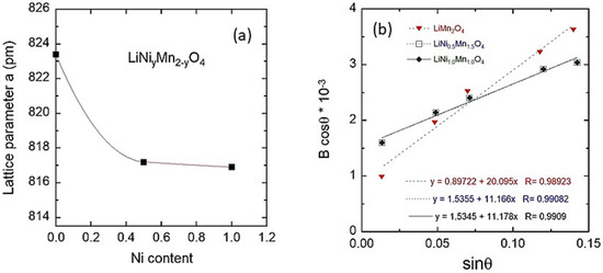
Figure 2.
(a) Evolution of the refined lattice parameters a and crystal volume V as a function of Ni content in LiNiyMn2−yO4 (0 ≤ x ≤ 1). (b) Analysis of the full-width B at half-maximum of XRD peaks according to Equation (1). B is expressed in radian (b).
Further information on structural properties can be obtained from the broadening of diffraction peaks that is considered as an indicator not only of the crystallinity of the spinel powder but also of the homogeneous distribution of cations within the structure. The microstrain (ε) of the particles was determined using the Williamson–Hall equation [32]:
where λ is the X-ray wavelength, K is the shape factor, Bhkl is the line broadening of a Bragg reflection (hkl) and Lc is the effective crystallite size. The microstrain is estimated from the slope of the plot Bhkl cos θhkl vs. (4 sin θhkl) and the intersection with the vertical axis provide the crystallite size. Bhkl value used here is the instrumental corrected one. From Figure 2b, the microstrain of 5.04 × 10⁻³ rd for LiMn2O4 decreases considerably to 2.79 × 10⁻³ rd for LiNi0.5Mn1.5O4 and LiNiMnO4@NMO samples, indicating the reduced local deformation of the structure in which the Ni2+ ions are substituting the Mn3+ Jahn–Teller ions. These values are consistent with those reported by Arrebola et al. [33].
Bhkl cos θhkl = (Kλ/Lc) + 4ε sin θhkl,
The surface area of an electrochemically active material is an important parameter for the determination of the exchange-current at the electrolyte–electrode interface and kinetics of Li+ ions in electrode. As shown in Table 2, the BET specific surface area of LMO is 1.79 m2g−1, which increases to 2.04 and 2.31 m2g−1 for LNM and LNM@NMO, respectively. The typical N2 adsorption-desorption isotherms are shown in Figure S4 (Supporting Information). The isotherm curves of the three samples display hysteresis loops indicating the hierarchical mesoporous structure of nanopowders. The mesopores (~13 nm in size) calculated using the Barrett–Joyner–Halenda (BJH) model correspond to the interconnecting voids existing between randomly packed nanoparticles. All isotherms increase with increasing P/P0 and forms a H3-hysteresis loop up to P/P0 ≈ 0.9 [78].
Table 2.
BET parameters of the LMO, LNM and LNM@NMO spinel samples.
Figure 3 presents the SEM images of spinel powders prepared by EDTA-assisted sol-gel method. Clearly, particles of submicron size with heterogeneous morphology have been formed with subsequent annealing at 600 °C for 12 h in air. LiMn2O4 (Figure 3a) and LiNiMnO4@NMO (Figure 3c) exhibit big and well-crystallized grains (>1 µm), whereas LiNi0.5Mn1.5O4 (Figure 3b) displays a more homogeneous size distribution of grains. A relative porosity is observed. According to the synthesis process, the formation of mesoporous structure partially originates from the releasing gases during firing the acetate precursors. The corresponding SEM images of electrodes fabricated using a slurry composed of the active material obtained via an additional grounding, conducting Super-P carbon black and PVdF binder are shown in Figure S3 in the Supporting Information.
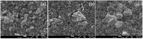
Figure 3.
SEM images of spinel powders prepared by EDTA-assisted sol-gel method. (a) LiMn2O4, (b) LiNi0.5Mn1.5O4 and (c) LiNiMnO4@NMO. The scale bar is 1 µm.
The structure and morphology of as-prepared spinel powders were further characterized using transmission electron microscopy (Figure 4a–i). For each compound, TEM image (200 nm scale), HRTEM image and SAED diagram are presented. TEM patterns show a significant difference in the particle shape upon substitution of Ni for Mn in the spinel framework. TEM images 4a and 4d show that most of the LMO and LNM particles are faceted with a regular octahedral shape. These nanoparticles adopted a well-defined polyhedral morphology with size in the range 100–200 nm. It implies that the low calcination temperature (600 °C) has an effect not only on the shape but also on the size of the particles [34]. In the TEM pattern of the LiNiMnO4@NMO composite (Figure 4g), primary particles have irregular shapes and are agglomerated, such a morphology being attributed to the presence of the secondary Ni6MnO8 phase. This implies that the coexistence of the LNM spinel and the secondary Ni6MnO8 phase results in a polycrystalline sample with a large proportion of irregularly shaped particles [35]. HRTEM images (Figure 4) enlarged from the selected area show lattice fringes with interplanar distance of 0.469, 0.471 and 0.465 nm for the LMO, LNM and LiNiMnO4@NMO samples, respectively. They match well with the (111) plane of the Fdm spinel phase. This is quite consistent with the low microstrain values obtained from X-ray broadening analysis [33]. In addition, a careful examination of HRTEM images of LNM and Ni-rich LNM reveals the presence of islands corresponding to the cubic Ni6MnO8 phase (Figure 4e,h). The good accommodation of LNM with NMO is due to their close cubic parameters (8.17 vs. 8.29 Å). The SAED patterns of LMO and LNM recorded on the selected area, show the characteristic diffraction spots of the Fdm spinel structure. The SAED pattern (Figure 4c) confirms that the LiMn2O4 powder is a single crystal. Similar features are observed for the LNM sample, whereas rings in the SAED image of Ni-rich LNM indicate a structural disorder with the presence of NMO islands in the spinel lattice.
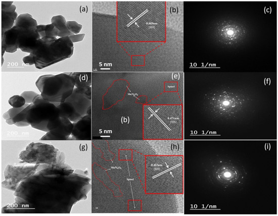
Figure 4.
HRTEM images and SAED patterns of LiMn2O4 (a–c), LiNi0.5Mn1.5O4 (d–f) and LiNiMnO4@Ni6MnO8 (g–i) powders synthesized by sol-gel method. Insets show fringes from selected well-crystallized zones.
Raman scattering (RS) spectra were recorded in the spectral range 120–800 cm−1 to identify the structure and probe the short-range environment within lattices, and the surface state of particles. The internal and external modes of vibration of the spinel phase are observed in this region. Raman patterns of LMO and LNM are shown in Figure S5 in the Supporting Information along with the vibrational mode attribution in Table S1. Raman patterns of the LNM@NMO composite were recorded at different locations on the surface of the sample. Figure 5 shows the typical spectrum obtained in many places of the surface and another spectrum from a Ni-rich region. Compared with the Raman pattern of LMO, the introduction of Ni2+ ions in the spinel lattice (Fdm S.G.) has modified the Raman features in a complicated manner. The Raman spectrum of the LNM@NMO composite displays 10 peaks appearing at 164, 220, 341, 403, 499, 520, 599, 612, 637 and 667 cm−1, which are the fingerprints of the Ni-doped spinel phase (see attribution in Table S1 in Supporting Information). These features match well with those of previous reports [14,17,36]. The strong band at 637 cm−1 band is associated with the symmetric Mn-O stretching vibration of MnIVO6 octahedra. The peaks at 403 cm−1 of medium intensity and 499 cm−1 of high intensity are unequivocally assigned to the Ni2+-O stretching mode. The A1g mode of the spinel appears as a broad bump with two components at 597 and 610 cm−1. The split of this A1g mode is assigned to the fingerprint of the P4332 ordered phase, which means a mixture of the Fdm disordered and P4332 ordered phases in sample annealed at 600 °C for 12 h. The peak splitting between bands at 386 and 473 cm−1 for LMO is reduced between the bands at 341 and 403 cm−1 for LNM due to the polyhedral distortion. The Raman spectrum of the Ni-rich spot of LiNiMnO4@Ni6MnO8 resembles to that of its parent LiNi0.5Mn1.5O4 except for the band at 579 cm−1, which is higher in intensity. Thus, the presence of Ni6MnO8 is detected in the spectrum of the Ni-rich spot. The vibrational activity of Ni6MnO8 originates from one-phonon mode appearing as a Raman peak at ~575 cm−1 (see inset in Figure 5) [37]. The presence of localized Ni6MnO8 domains in the composite sample evidenced by the strong Raman pattern at 579 cm−1 is consistent with the XRD data.
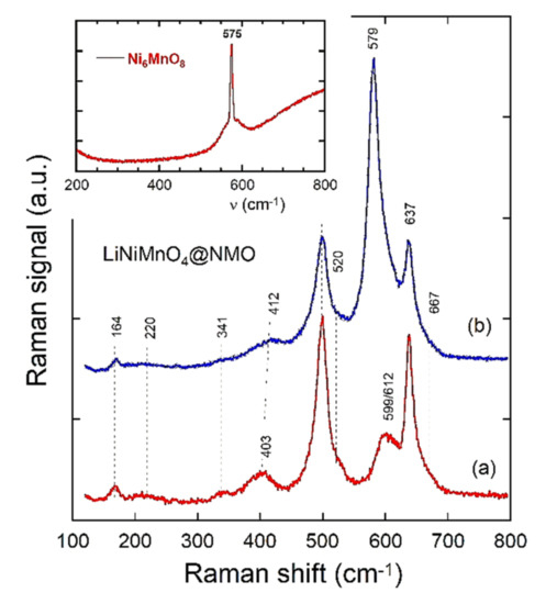
Figure 5.
Raman spectra of the LNM-NMO composite recorded on different places using a spectral resolution of 1 cm−1 and the excitation source at 532 nm. (a) Domain of pure LNM and (b) Ni-rich domain with Ni6MnO8 clusters.
X-ray photoelectron spectroscopy was used to identify the surface of spinel particles and the content of Mn3+ ions located on the crystal surface. The XPS survey spectra of the three spinel samples are shown in Figure S4a in Supporting Information. Figure 6 presents the related XPS spectra in the binding energy region of O 1s, Mn 2p and Ni 2p for LiNiMnO4 synthesized by EDTA-assisted sol-gel method. The binding energies (BEs) compared with those of LMO and LNM are presented in Table 3. The XPS spectrum of O 1s is mainly composed of two peaks: A sharp feature at 529.4 eV, which originates from the oxygen atoms in the LiNiMnO4 crystalline network; and the other peak at 531.3 eV, which can be ascribed to the oxygen in carbonate species (i.e., C=O bonds; Figure 6a). These BEs match well with the values of literature [38,39,40]. Mn 2p and Ni 2p core levels give a weak signal. In the spectrum of Mn 2p (Figure 6b), there are two main characteristic peaks assigned to Mn 2p3/2 (642.2 eV) and Mn 2p1/2 (653.9 eV) with a spin-orbit energy separation of 11.7 eV, which is in good agreement with the values of the literature [41,42,43,44]. Figure 6c presents the XPS spectrum in the Ni 2p region, which displays two main peaks with their respective satellite. The Ni 2p3/2 and its satellite are located at 854.4 and 860.2 eV, respectively, whereas those of Ni 2p1/2 are at 871.1 and 876.7 eV, respectively. Results are listed in Table 3 along with those obtained from LMO and LNM samples. The XPS valence band spectra of the three spinel samples are presented in Figure S4b in the Supporting Information. All spectra show a similar two-region structure: A sharp peak located at ~3.3 eV close to the Fermi level and a less intense broad band at ~7 eV. This band is mainly due to the O 2p states, which are hybridized with the Mn 3d states.
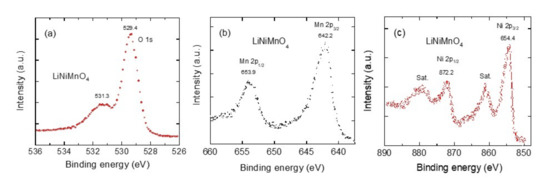
Figure 6.
XPS analysis of LiNiMnO4 spinel powder synthesized by sol-gel method. (a) XPS spectrum of the O 1s region. (b) XPS spectrum of the Mn 2p region. (c) XPS spectrum of the Ni 2p region. Satellite peaks are marked by “Sat”.
Table 3.
Binding energies of Mn and Ni core levels for the spinel compounds.
3.2. Electrochemical Properties
3.2.1. Cyclic Voltammetry and Charge-Discharge Profiles
The electrochemical intercalation/deintercalation behavior of the synthesized LNM@NMO nanocomposite materials was examined through cyclic voltammetry and galvanostatic charge/discharge cycling using CR2032-type coin cells (Figure 7) and compared with the performance of LNM and LNM parents (Figures S6 and S7 in Supporting Information). Figure 7a presents the first to fifth cyclic voltammograms of the LNM@NMO electrode carried out in the potential between 4.4 and 4.9 V at a low scan rate of 0.02 mV s−1. The first CV curve displays well-resolved and reversible anodic current peaks observed at 4.71 and 4.78 V (charge reaction) and cathodic current peaks at 4.64 and 4.68 V corresponding to the discharge process. Whereas the Li-ion extraction/insertion takes place with the redox reaction of Mn3+/Mn4+ at 4 V (very weak current peak intensity) in the LMO spinel lattice, the process occurring at ca. 4.7 V in the LNM spinel network is due to the Ni2+/Ni3+ and Ni3+/Ni4+ redox reactions [16]. A careful examination of the electrochemical response at ca. 4 V shows weak anodic/cathodic peaks due to the Mn3+/Mn4+ redox reaction, which implies the presence of a small amount of manganese in the +3 state. These electrochemical patterns confirm the non-stoichiometric nature (Fdm spinel phase) of the LMN@NMO composite, while the ordered LNM phase (P4332 S.G.) shows only a strong peak around 4.75 V vs. Li+/Li [45,46,47]. Both LiNiMnO4@Ni6MnO8 and LiNi0.5Mn 1.5O4 show almost the same redox peaks location, considering the Ni6MnO8 phase as electrochemical inactive in the investigated potential range. As shown in Figure 7b, the LNM@NMO composite electrode is unstable during the first five cycles. A slight shift of ~60 mV occurs due to the cell formation, which can originate from the growth of a cathode electrolyte interphase (CEI) layer at the electrode surface [79,80,81,82]. It is known that the CEI layer plays an essential role in determining the electrochemical performance of Li-ion batteries. Recently, Li et al. [82] investigated the fundamental process of cathode electrolyte interphase formation in high-voltage cathodes and demonstrated that the spinel cathode exhibits the most stable CEI layer throughout the battery cycle. The complex CEI behavior can be assigned to a series of entangled processes including CEI component dissociation and dissociated CEI species redeposition. The polarization degree can be evaluated by the potential difference (ΔΦ) between the anodic (Φa) and cathodic (Φc) peaks. Results listed in Table 4 show that the LNM@NMO electrode is more resistive than the LNM one.
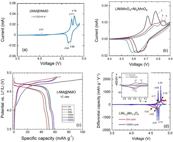
Figure 7.
Electrochemical performance of the LiNiMnO4@Ni6MnO8 composite electrode. (a) Cyclic voltammograms recorded at the slow scan rate 0.02 mV s−1 in the voltage range 3.5–4.9 V. (b) First to fifth detailed CV responses in high voltage region. (c) GCD profiles carried out at 1C rate in the voltage between 3.5 and 4.9 V upon 1000 cycles. (d) Differential capacity analysis (−dQ/dV) vs. voltage for the second and 1000th cycles.
Table 4.
Values of the CV peaks (Φanodic and Φcathodic in V) and the potential difference (ΔΦ in mV) for LNM@NMO and LNM electrode materials prepared by EDTA-assisted sol-gel method.
Figure 7c presents the GCD profiles for LNM@NMO//Li cells. The cells were cycled 1000 times at 1C rate (1C = 148 mA g−1) in the potential range 3.5–4.9 V vs. Li+/Li, whereas the GCD responses of parents LMO and LNM are presented in Figures S6 and S7, respectively. All charge-discharge curves of the LNM@NMO electrode display two voltage plateaus at high potential of 4.65 and 4.70 V, and at ~4.0 V consistent with the CV diagrams corresponding to the Ni2+/3+, Ni3+/4+ and Mn3+/4+ redox reactions, respectively. The initial discharge capacity is 52 mAh g−1 with a Coulombic efficiency of 92%, which increases to 59 mAh g−1 in the subsequent several cycles after the cell formation and electrode activation processes (until 50 cycles) and remains almost at 57 mAh g−1 (with a Coulombic efficiency of 99.2%) over 1000 cycles. These values are very low in comparison with those delivered by the pristine LNM material because of the presence of the secondary Ni6MnO8 inactive phase. The existence of this phase would lead to a lower specific capacity of the prepared sample, as it was also included in the calculation of the total mass of the active material [48]. The capacity in the 4-V region is ~10% of the total capacity delivered by the LNM@NMO composite electrode, that means a sufficient amount of Mn3+ cations in the bulk, which can increase the conductivity and favors the migration of Li+ in the lattice [49]. Such as Raman spectroscopy and cyclic voltammetry, the differential capacity analysis (−dQ/dV) vs. V is not only used to analyze the lithiation/delithiation processes (i.e., study of redox potentials at low and high potentials) in LMO electrodes but is also a tool of choice to discriminate between the Fdm and P4323 LNM polymorphs. In this analysis, one differentiates the charge/discharge capacity (Q = ∫ Idt) from data in GCD curves (Figure 7c) with respect to the cell voltage. The (−dQ/dV) vs. V curves transform voltage plateaus on the V-Q curves into peaks, which further characterize the electrochemical reactions and identify the gradual changes (if any) after the subsequent lithiation/delithiation process [50,51].
In Figure 7d, we present the (−dQ/dV) vs. V plots recorded during the second and the 1000th cycles for the LNM@NMO composite cathode material. The structural instability of the electrode during the second cycle is confirmed by the shift of the redox peak toward higher potential after the formation process. After 1000 cycles, the electrode reaches stability and the differential capacity pattern exhibits pairs of sharp peaks (i.e., two anodic peaks at 4.69 and 4.76 V plus two cathodic peaks at 4.67 and 4.72 V), which is in good agreement with the voltage pseudo-plateaus fingerprints of the Ni2+/3+ and Ni3+/4+ redox reactions in the disordered LMN lattice (Fdm phase). These plots reveal the presence of redox peaks at 4 V, which are caused by the Mn3+ content. Note the significant decrease of the difference between oxidation and reduction potentials ΔV = Vox − Vred from 150 mV (second cycle) to 40 mV (1000th cycle), which is due to the change in cell polarization occurring after the electrode formation (i.e., surface modification, growth of CEI). The lithiation of the Ni6MnO8 domains is also possible [83].
Rate capability tests of the three spinel samples were performed at a constant charge rate (1C) and different discharge rates (0.1, 0.5, 1, 2 and 5C) in voltage window 3.5–4.9 V vs. Li+/Li. Figure 8a displays the results for LMO, LNM and LNM@NMO electrodes. The LMO electrode exhibits the typical behavior of the pristine spinel structure with a continuous decrease of the discharge capacity with the increasing current rate, retaining 56 mAh g−1 when cycled at a high rate of 5C (700 A g−1). In contrast, LNM and LNM@NMO electrodes show a good retaining rate of discharge capacity for the current rate 0.1C–2C. For the LNM@NMO electrode, we observe an increase of capacity from 0.1C to 1C, which indicates an activation process at a high current rate. The LNM@NMO electrode maintains an almost constant capacity of 60 mAh g−1 up to 2C rate, which decreases to ~35 mAh g−1 at 5C rate. These electrochemical features match well with those reported by several researchers [52,53]. Spence et al. [53] attributed this increased discharge capacity behavior to the oxygen deficiency and the presence of Mn3+ content in the LNM lattice induced at different synthesis temperatures. As shown in Table S2 in Supporting Information, the long-term electrochemical performance of the as-prepared LNM electrode, with δ(Mn3+) = 0.035, compares well with those of literature. A capacity retention of 34% remains after 1000 cycles at 1C current rate (i.e., decay of 0.04 mAh g−1 per cycle).
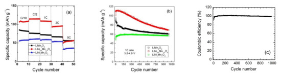
Figure 8.
(a) Rate capability with discharging at various C rates for spinel electrodes prepared by EDTA-assisted sol-gel method. (b) Cyclability performance of electrodes cycled at 1C rate in voltage window 3.5–4.9 V vs. Li+/Li. (c) Coulombic efficiency of the LNM@NMO composite electrode.
The cyclability performances of the spinel electrodes cycled at the rate of 1C in the potential range 3.5–4.9 V vs. Li+/Li are presented in Figure 8b. After 1000 cycles, the LMO electrode retains ~63% of its first discharge capacity, while LNM provides 61.3%. On the contrary, the Ni-rich composite restores 119 % of the initial discharge capacity. As shown in Figure 8b, the Ni-rich material exhibits an initial specific capacity of 49 mAh g−1 and a coulombic efficiency of 92%, which increase to 59.7 mAh g−1 and 99.2%, respectively, after 120 cycles due to the activation of the material (Figure 8c). An excellent stabilization of the lithium insertion/deinsertion process with a very small capacity decay (2.5 mAh g−1 over 900 cycles) after the activation observed in the first 100 cycles. The specific capacity remains almost at 57.2 mAh g−1 over 1000 cycles, showing a remarkable small decay of 2.7 × 10⁻³ mAh g−1 per cycle. Thus, the presence of 37.2% Ni6MnO8 in the composite reduces considerably its initial discharge capacity (~50%) by almost the same percentage (51.7%) of the weight of the inactive component but seems to be beneficial in terms of electrode stability. The increase of capacity until the 100th cycle may be attributed to the decreasing electrode impedance as verified in the next section.
3.2.2. Electrochemical Impedance Spectroscopy (EIS)
To further investigate the electrochemical kinetics and understand the improved electrochemical properties of LiNiyMn2−yO4 (0.0 ≤ y ≤ 1.0) electrode materials, the electrochemical impedance spectroscopy (EIS) was carried out on a fresh cell and after 1000 cycles at 1C rate. Figure 9a–e shows the Nyquist plots for LMO, LNM and LNM@NMO electrodes and the analysis of the low-frequency region (diffusional part). The equivalent circuit model used to analyze the Nyquist plots is shown in Figure 9c. According to a usual assignment, components of the equivalent circuit are composed of a series of four elements: The cell resistance Rs, a resistance in parallel with a constant phase element corresponding to the solid electrolyte interphase (SEI) layer, a second R-CPE parallel component, which figures out the charge transfer process and finally the diffusion Warburg component (W). All Nyquist plots in Figure 9a,b, can be decomposed according to the equivalent circuit described above: (i) The intercept at high frequency with the Z’-axis is related to the uncompensated ohmic resistance of the cell (Rs); (ii) in the high-frequency region, the first depressed semicircle is associated with the SEI (RSEI, CPESEI); (iii) a second depressed semicircle in the medium-frequency region is ascribed to the charge transfer impedance and interfacial capacitance at the electrode/electrolyte interface (Rct, CPEdl); and (iv) in the low-frequency range, the inclined line is ascribed to the Li+-ion diffusion-controlled process characterized by the Warburg impedance ZW(ω) = σw (1 − j) ω−1/2, where σw is the Warburg factor, ω is the frequency and j = √−1 [54]. From Nyquist plots, it can be seen that the general trend is a decrease of the total impedance after 1000 cycles at 1C rate for all spinel electrodes. The internal resistances (Rs) of the fresh cells are below 10 Ω and remain almost unchanged during the cycling process. However, Rs of Ni-rich electrode is smaller than that of bare spinel because the partial substitution of Ni for Mn3+ in LNMO leads to a significant increase in electronic conductivity. The other electrical parameters of the spinel electrodes, such as RSEI and Rct, show a significant increase upon cycling, which provokes, as shown in GCD curves, the increases of the cell polarization after long-term cycling. Moreover, the increase of RSEI and Rct impedes the Li-ion kinetics (i.e., lowering the diffusion coefficient). EIS fitting parameters are reported in Table 5.
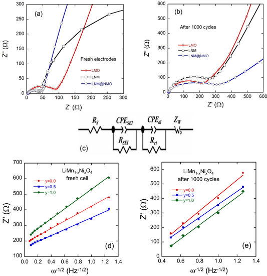
Figure 9.
EIS measurements (Z” vs. Z’ plots) of LiNiyMn2−yO4 (y = 0, 0.5 and 1.0) electrodes: (a) Fresh electrodes, (b) after 1000 cycles at 1C. (c) Plots of the real part of the impedance vs. ꞷ−1/2 for (d) fresh electrodes and (e) after 1000 cycles. The inset presents the equivalent circuit.
Table 5.
Fitting results of Nyquist plots for the LiNiyMn2−yO4 (y = 0, 0.5 and 1.0) electrodes before cycling and after the 1000th cycle: cell resistance Rs, SEI resistance RSEI, charge-transfer resistance Rct and diffusion coefficient DLi+.
The real part Z’(ω) of the total impedance of the cell is the sum of the real part of the four components:
Z’(ω) = Rs + RSEI + Rct + σw ω−1/2.
Figure 9d,e presents the plots of Z’(ω) vs. ω−1/2 for the spinel electrodes, from which the slope σw can be determined for the calculation of the apparent diffusion coefficient DLi according to the following relation [55]:
in which R is the gas constant, T the absolute temperature, F the Faraday’s constant, n the number of electrons transferred, CLi is the concentration of Li+-ion inside the electrode, and A the effective surface area of the electrode. Values of the apparent diffusion coefficient DLi in spinel electrode before and after cycling are listed in Table 5. DLi has the same magnitude for the three spinel electrodes (~10−12 cm2 s−1). A slight decrease is observed after a long-term cycling (less than one order of magnitude), which is consistent with the increased values of RSEI and Rct. According to the literature data, the apparent DLi for fresh LNM spinel cathode material is varied in the range from 10−12 to 10−13 cm2 s−1 [56,57].
3.2.3. Area-Specific Impedance (ASI)
More information on the change in the overall cell potential as a function of the depth-of-discharge (DOD) can be obtained by evaluating the area-specific impedance (ASI expressed in Ω cm2) given by the relation [51,58]:
where A is the cross-sectional area of the electrode, ΔV = OCV − Vcell is the potential change during current interruption for 60 s at each DOD and I is the current passed throughout the cell. Various factors can affect the area-specific impedance including ohmic drop, Li-ion transport through the electrolyte and solid-state diffusion within the electrode. Moreover, ASI does not need to reach equilibrium conditions, as in the case of EIS, which makes this technique more representative for the total internal resistance evaluation during cycling.
Figure 10a,b displays the variation of ASI for the LiNiyMn2−yO4 (y = 0.0, 0.5 and 1.0) electrodes before and after 1000 cycles at 1C rate, respectively. At 90% DOD, ASI values of 55, 64 and 81 Ω cm2 are measured for LMO, LNM and LNM@NMO fresh cell (first cycle), respectively, which become 80, 65 and 43 Ω cm2 after long-term cycling (1000th cycle). These results indicate that charge-transfer resistance is dependent on DOD and also the aging of the electrode. However, the LNM@NMO electrode seems to have a better performance after long-term cycling. We believe that the decrease in ASI associated with the increase of specific capacity after 50 cycles could be ascribed to the intrinsic activation of the Ni-rich material, in which the secondary NMO phase works as an interfacial stabilizer. These results match well with the work by Amine et al. [58], who reported an ASI of 25 Ω·cm2 for a LiMn2O4 electrode. Kim et al. [59] reported ASI values of 55 and 75 Ω·cm2 for LiMn1.5Ni0.5O4 (Fdm) and LiMn1.5Ni0.5O4 (P4332) phase, respectively.
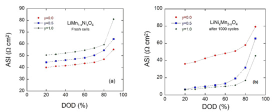
Figure 10.
Area specific impedance (ASI) of parent and Ni-doped LiMn2O4 as a function of depth of discharge (DOD) (a) before and (b) after 1000 cycles.
4. Discussion
Our aim of this work was to ascertain what would happen if we increase the amount of Ni in LiNixMn2−xO4 with x > 0.5. To the best of our knowledge, the composition LiNiMnO4 has never been reported as a cathode material. As experimental results, there was significant stabilization in the cycling with negligible capacity fading, as we reported also. This means that there was excellent capacity retention over 1000 cycles at the expanse of the initial capacity. This low initial capacity is not practical as a cathode material in a high power battery. However, the LiNiMnO4 could be used in some applications requesting long-term electrochemical stability. Here, we concentrate on the fundamental scientific point of view. It is well known that all electrode materials show low initial coulombic efficiency in the first cycles, which then increases with repeating cycles. For the Ni-rich material, we found an initial specific capacity of 49 mAh g−1 and a coulombic efficiency of 92%, which increase to 59.7 mAh g−1 and 99.2%, respectively, after 120 cycles, due to the activation of the material. The specific capacity remains almost at 57.2 mAh g−1 over 1000 cycles, showing a remarkable small decay of 0.0027 mAh g−1 per cycle, while the LiNi0.5Mn1.5O4 cathode displays a decay of 0.04 mAh g−1 per cycle. Recently, the Karlsruhe Institute of Technology (KIT)’s group stated that the introduction of a small quantity of Fe in LNM led to improvements in electrochemical performance owing to the suppression of Ni6MnO8, but the Fe doping did not significantly improve the capacity decay [84].
In this work, the nanostructured Ni-rich spinel materials were prepared through a wet-chemical process assisted by a chelator (EDTA), which acted as fuel and reducing agent for the metal acetates precursors. Unlike the conventional solid-state method, sol-gel is a facile, time-saving, cost-effective and low-temperature route to obtain nanostructured particles with a narrow particle size distribution that improves Li-ion transport and promotes high rate capability. Zhang et al. [60] studied the effect of chelators on the properties of sol-gel synthesized materials and confirmed the choice of a chelator that directly affects the electrochemical performance of electrode materials. Similar trends were found for the high-efficiency LiCoO2 and LiMn2O4 cathodes [20,61]. In comparison, the citric acid (or tartaric acid) used alone for the fabrication of cathode materials under the same conditions has shown less performance. Recently, Abdel-Ghany et al. [62] showed that, among various weak acids, EDTA is an excellent complexing agent to synthesized Li-rich Li1.2Ni0.13Co0.13Mn0.54O2 cathode materials.
It is well known that two LNM crystallographic forms exist—the nonstoichiometric LiNi0.5Mn1.5O4−δ (so-called disordered phase) and the stoichiometric LiNi0.5Mn1.5O4 (ordered phase)—which crystallize in the face-centered spinel Fdm structure and the simple cubic P4332 lattice, respectively, which exbibit similar XRD patterns. Different techniques are used to distinguish these forms including Raman spectroscopy, selected-area electron diffraction (SAED) study, cyclic voltammetry, and differential capacity measurements. It has unambiguously shown that the large voltage gaps between redox peaks in the (−dQ/dV) vs. V plots and the well-defined plateau in the voltage profile are the signatures of the LNM Fdm phase, in contrast with the P4332 form, which displays narrower voltage gaps at ~4.75 V and results in a flatter voltage profile. Note that the Fdm polymorph is always accompanied with a rock-salt impurity phase, such as NixO, LixNi1−xO, (LiMnNi)xO and Ni6MnO8, which appears concomitantly with oxygen deficiency in the spinel framework [63,64].
Rietveld refinements have confirmed the presence of the Ni6MnO8 phase as impurities in the Ni-doped LiMn2O4 spinel. A low concentration of 2.7% was found in the LMN sample, whereas the NMO contains 37.2% of Ni6MnO8. It is well known that the high temperature process causes the formation of the impurity phase by the formation of oxygen deficiency and partial reduction of Mn4+ to Mn3+. Many studies have found that NiO [64,65,66], LixNi1−xO [67,68,69,70] and Ni6MnO8 [30,31,35,71,72] are common impurity phases in LiNiyMn2−yO4 (0.1 ≤ y ≤ 0.5) materials. Many researchers believed that impurities are lowering the capacity and blocking Li+ mobility in the electrode material; however, in several reports, these conclusions are not obvious. The early work by the Dahn’s group [63] shows that the formation of Li0.2Ni0.8O (or NiO) results from the Ni deficiency in the LNM structure. This means that extra amounts of Ni remain in the powder synthesized by either solid-state or sol-gel method. Xue and coworkers showed that an inhomogeneous atoms migration may introduce Mn3+ and LixNi1−xO impurity phases in the spinel [70]. Samples were prepared with the content of LixNi1−xO impurity from 10.4% to 28.1%. They revealed that the difference in the Mn3+ and impurity contents do not originate from a loss of oxygen at high-temperature conditions but are rather related to some difference of their precursor particles microstructures.
Except for the modest value of the delivered discharge capacity (57 mAh g−1 at 1C rate) due to the large amount of impurity NMO phase, the as-prepared LNM@NMO composite shows non-conventional electrochemical behaviors: (a) An initial increase of discharge capacity during the regime of formation (~40 cycles); (b) a decrease of the cell polarization; and (c) a quasi-constant capacity retention of 97% after 1000 cycles (i.e., very low capacity fading of 0.002 mAh g−1 per cycle). Despite the low discharge capacity around 60 mAh g−1 at 1C rate, the oxygen non-stoichiometry δ =0.04 (calculated from XPS measurements) in LNM@NMO composite yields enhanced electrochemical performance and an excellent stability over 1000 cycles. While the electron transfer is dominated by the Ni2+/3+ Ni3+/4+ hopping in the ordered P4332 phase, additional hopping paths Ni2+/3+ Mn4+ Mn3+ Ni3+/4+ contribute to the electronic conduction in the disordered Fdm phase.
The capacity ratio between the 4.0 V region and the 4.7 V region (Q4.0/Q4.7 = 0.12), measured after a discharge rate of 1C. corresponds to the amount of 0.035 Mn3+ per formula unit of LNM prepared by the EDTA-assisted sol-gel method, with subsequent annealing at 600 °C. In 2012, the Goodenough’s group [76] compared the structural and electrochemical properties of LNM spinels with various Mn3+ (δ) contents and reported Q4.0/Q4.7 ratios of 0.21 (δ = 0.16) and 0.11 (δ = 0.09) for fast-cooled and slow-cooled LNM samples, respectively. In these samples, the disordered structure is characterized by an increase of the “a” lattice parameter from 8.1789 to 8.1827 Å, respectively. Liu et al. [77] reported similar trend with a ratio Q4.0/Q4.7 = 0.23 for 0.14 Mn3+ content. Thus, our results of Q4.0/Q4.7 = 0.10, δ = 0.04 and a = 8.176(2) Å for a pristine LMN sample prepared at slow-cooling rate are consistent with previous data.
EIS measurements of the LNM@NMO composite are consistent with the patterns observed in GCD profiles, and reveal that both the oxygen deficiency and the Ni/Mn disordering contribute to different rate performances and play a key role in electronic conduction in LiNi0.5Mn1.5O4−δ cathode materials. It is worthy to note that the variation of the cell resistance is associated with the electrode activation up to the 100th cycle. A significant decrease in cell polarization is observed after 1000 cycles, which is also revealed by the ASI vs. DOD measurements.
5. Conclusions
In this work, for the first time, we investigated the physical and electrochemical properties of the Ni-rich 5-V spinel with high degree y = 1 of Ni2+ substituted for Mn4+ in LiNiyMn2−yO4. For a better understanding of the material, we prepared a LiMn2O4 and LiNi0.5Mn1.5O4 bare spinel and compared all patterns with the new compound. When synthesized by the EDTA-assisted sol-gel method, the Ni-rich material crystallized in the form of a composite, which consists of two phases: the non-stoichiometric LiNiMnO4−δ (Fdm) spinel phase and the secondary Ni6MnO8 (Fm3m) phase (i.e., LNM@NMO composite). Rietveld refinements reveal the composition (1-z)LiNiMnO4·zNi6MnO8 with z = 37.2. Thus, when 0.5Ni is introduced in the LiNi0.5Mn1.5O4 lattice, only 15.5% Ni2+ ions participate in the Fdm spinel phase. The LNM@NMO composite exhibits a mesoporous structure with average pore width of ~13 nm, which corresponds to the interconnecting voids existing between randomly packed nanoparticles. Raman spectroscopy confirms the presence of the secondary phase by a strong active mode at ~579 cm−1, which originates from the one-phonon mode of the Ni6MnO8 crystal. The analyses of structural disorder carried out by XRD and XPS measurements show the amount of Mn3+ ions of δ = 0.04 and 2.6% Ni2+ ions in 8a sites (antisite defects) in the LMN@NMO sample. The LiNiMnO4@Ni6MnO8 composite electrode exhibits electrochemical behavior identical to LiNi0.5Mn1.5O4. Cyclic voltammetry displays the two sets of anodic and cathodic peaks (corresponding to the voltage plateaus in GCD curves at ca. 4.7 V), which are due to the Ni2+/Ni3+ and Ni3+/Ni4+ redox reactions, whereas the redox couple at ~4 V (with very weak current peak intensity) originates from the Mn3+/Mn4+ reaction (i.e., fingerprint of the oxygen deficiency in the “disordered” spinel structure). Despite its low initial specific capacity due to the presence of the electrochemically inactive secondary phase, the LMN@NMO cathode material displays a remarkable stable cyclability behavior (~57 mAh g−1) with a capacity loss of only 2 × 10⁻³ mAh g−1 per cycle after 1000 cycles at 1C rate. The decrease in ASI associated with the increase of specific capacity after 50 cycles could be ascribed to intrinsic activation of the Ni-rich material, in which the secondary NMO phase works as an interfacial stabilizer. Another important aspect of this work was evidenced by the combination of EIS and ASI characterizations: As an experimental result, the origin of the high electrochemical stability of the LNM@NMO composite. The variation of the cell resistance is associated with the electrode activation up to the 100th cycle and the significant decrease in cell polarization is attributed to the initial electrode activation and to the formation of the most stable CEI layer throughout the cell cycle.
Supplementary Materials
The following are available online at https://www.mdpi.com/2673-3293/2/1/9/s1, Figure S1: Schematic representation of the synthesis of Li-Ni-Mn-O spinel materials using the EDTA-assisted sol-gel method with subsequent annealing at moderate temperature; Figure S2: Schematic representation of the coin-cell assembly; Figure S3: SEM images of electrodes fabricated using the slurry composed of active material, conducting Super-P carbon black and PVdF binder. (a) LiMn2O4, (b) LiNi0.5Mn1.5O4 and (c) LiNiMnO4@NMO. The scale bar is 1 µm; Figure S4. Nitrogen adsorption/desorption isotherms for (a) LiMn2O4, (b) LiNi0.5Mn1.5O4 and (c) LiNiMnO4@NMO; Figure S5: Raman spectra recorded with the excitation line at λ = 532 nm of (a) LiMn2O4 and (b) LiNi0.5Mn1.5O4 spinels; Table S1: Raman mode attribution for LiMn2O4, LiNi0.5Mn1.5O4 LiNiMnO4@NMO. w—weak, m—medium, s—strong, vs—very strong, b—broad; Figure S6: XPS characterization of LMP, LNM and LNM@NMO spinel powders synthesized by sol-gel method: (a) Survey spectra, (b) XPS valence band spectra. Figure S7: Electrochemical performance of LiMn2O4. (a) Cyclic voltammograms (three cycles) recorded at the scan rate of 0.02 mV s−1. (a) Galvanostatic charge-discharge profiles carried out at 148 mA g−1 current rate in the potential window 3.5–4.9 V. (c) Differential capacity (−dQ/dV) vs. potential of the LiNi0.5Mn1.5O4 electrode in 1 mol L−1 LiPF6 in EC:DEC (1:1) electrolyte; Figure S8: Electrochemical performance of LiNi0.5Mn1.5O4. (a) Cyclic voltammograms (three cycles) recorded at the scan rate of 0.02 mV s−1. (a) Galvanostatic charge-discharge profiles carried out at 148 mA g−1 current rate in the potential window 3.5–4.9 V. (c) Differential capacity (−dQ/dV) vs. potential of the LiNi0.5Mn1.5O4 electrode in 1 mol L−1 LiPF6 in EC:DEC (1:1) electrolyte; Table S2: Electrochemical performance upon long-term cycling of LNM cathode materials synthesized by different methods. The discharge capacity of fresh LNM//Li cells and that after cycling is documented. The relevant cycle number is given in brackets; References.
Author Contributions
Conceptualization, L.Z. and A.M.H.; formal analysis, A.E.A.-G., R.S.E.-T., T.L. and K.C.; investigation, A.E.A.-G., R.S.E.-T., T.L., K.C. and H.W.; writing—original draft preparation, A.M.H., A.E.A.-G., and R.S.E.-T.; writing—review and editing, C.M.J., H.E.-M., A.T., L.Z. and A.M.H.; supervision, L.Z. and A.M.H., project administration L.Z. and A.M.H., funding acquisition, L.Z. and A.M.H. All authors have read and agreed to the published version of the manuscript.
Funding
This article is derived from the Subject Data funded in part by USAID and NAS through Subaward 2000010562, and that any opinions, findings, conclusions, or recommendations expressed in such article are those of the authors alone, and do not necessarily reflect the views of USAID or NAS.
Institutional Review Board Statement
Not applicable.
Informed Consent Statement
Not applicable.
Data Availability Statement
Data is contained within the article or supplementary material.
Acknowledgments
Egyptian authors are grateful to financial support from Science, Technology and Innovation Funding Authority (STIFA, STDF previously) through project number 42691 entitled (Microstructure-based, multi-physics simulation and optimization to improve battery performance). The authors would like to thank Professor Shixiong Zhang and Amanda Coughlin of the Department of Physics at Indiana University-Bloomington for their assistance with Raman spectroscopy analysis. Access to XPS at the Nanoscale Characterization Facility at Indiana University is acknowledged.
Conflicts of Interest
The authors declare no conflict of interest.
References
- Zaghib, K.; Dontigny, M.; Guerfi, A.; Charest, P.; Rodrigues, I.; Mauger, A.; Julien, C.M. Safe and fast-charging Li-ion battery with long shelf life for power applications. J. Power Sources 2011, 196, 3949–3954. [Google Scholar] [CrossRef]
- Berckmans, G.; Messagie, M.; Smekens, J.; Omar, N.; Vanhaverbeke, L.; Van Mierlo, J. Cost projection of state of the art lithium-ion batteries for electric vehicles up to 2030. Energies 2017, 10, 1314. [Google Scholar] [CrossRef]
- Perner, A.; Vetter, J. Lithium-ion batteries for hybrid electric vehicles and battery electric vehicles. In Advances in Battery Technology for Electric Vehicles; Scrosati, B., Garche, J., Tillmetz, W., Eds.; Woodhead Publishing: Oxford, UK, 2015; pp. 173–190. [Google Scholar]
- Julien, C.M.; Mauger, A. Review of 5-V electrodes for Li-ion batteries: Status and trends. Ionics 2013, 19, 951–988. [Google Scholar] [CrossRef]
- Julien, C.M.; Mauger, A.; Zaghib, K.; Groult, H. Comparative issues of cathode materials for Li-ion batteries. Inorganics 2014, 2, 132–154. [Google Scholar] [CrossRef]
- Gummow, R.J.; De Kock, A.; Thackeray, M.M. Improved capacity retention in rechargeable 4 V lithium/lithium manganese oxide (spinel) cells. Solid State Ion. 1994, 69, 59–67. [Google Scholar] [CrossRef]
- Lu, J.; Zhou, C.; Liu, Z.; Lee, K.S.; Lu, L. LiMn2O4 cathode materials with large porous structure and radial interior channels for lithium ion batteries. Electrochim. Acta 2016, 212, 553–560. [Google Scholar] [CrossRef]
- Ebin, B.; Battaglia, V.; Gürmen, S. Comparison of 4 V and 3 V electrochemical properties of nanocrystalline LiMn2O4 cathode particles in lithium ion batteries prepared by ultrasonic spray pyrolysis. Ceram. Int. 2014, 40, 7029–7035. [Google Scholar] [CrossRef]
- Zhan, C.; Lu, J.; Kropf, A.J.; Wu, T.; Jansen, A.N.; Sun, Y.; Qiu, X.; Amine, K. Mn(II) deposition on anodes and its effects on capacity fade in spinel lithium manganate–carbon systems. Nat. Commun. 2013, 4, 2437. [Google Scholar] [CrossRef]
- Li, X.; Xu, Y.; Wang, C. Suppression of Jahn-Teller distortion of spinel LiMn2O4 cathode. J. Alloys Compd. 2009, 479, 310–313. [Google Scholar] [CrossRef]
- Xu, G.J.; Liu, Z.H.; Zhang, C.J.; Cui, G.L.; Chen, L.Q. Strategies for improving the cyclability and thermo-stability of LiMn2O4-based batteries at elevated temperatures. J. Mater. Chem. A 2015, 3, 4092–4123. [Google Scholar] [CrossRef]
- Yi, T.F.; Mei, J.; Zhu, Y.R. Key strategies for enhancing the cycling stability and rate capacity of LiNi0.5Mn1.5O4 as high-voltage cathode materials for high power lithium-ion batteries. J. Power Sources 2016, 316, 85–105. [Google Scholar] [CrossRef]
- Amarilla, J.M.; Petrov, K.; Picó, F.; Avdeev, G.; Rojo, J.M.; Rojas, R.M. Sucrose-aided combustion synthesis of nanosized LiMn1.99-yLiyM0.01O4 (M = Al3+, Ni2+, Cr3+, Co3+, y = 0.01 and 0.06) spinels: Characterization and electrochemical behavior at 25 and 55 °C in rechargeable lithium cells. J. Power Sources 2009, 191, 591–600. [Google Scholar] [CrossRef]
- Zhu, W.; Liu, D.; Trottier, J.; Gagnon, C.; Howe, J.; Mauger, A.; Julien, C.M.; Zaghib, K. In-situ Raman spectroscopic investigation of LiMn1.45Ni0.45M0.1O4 (M = Cr, Co) 5-V cathode materials. J. Power Sources 2015, 298, 341–348. [Google Scholar] [CrossRef]
- Cai, Z.; Ma, Y.; Huang, X.; Yan, X.; Yu, Z.; Zhang, S.; Song, G.; Xu, Y.; Wen, C.; Yang, W. High electrochemical stability Al-doped spinel LiMn2O4 cathode material for Li-ion batteries. J. Energy Storage 2020, 27, 101036. [Google Scholar] [CrossRef]
- Ohzuku, T.; Takeda, S.; Iwanaga, M. Solid-state redox potentials for Li[Me1/2Mn3/2]O4 (Me: 3d-transition metal) having spinel-framework structures: A series of 5 volt materials for advanced lithium-ion batteries. J. Power Sources 1999, 81–82, 90–94. [Google Scholar] [CrossRef]
- Amdouni, N.; Zaghib, K.; Gendron, F.; Mauger, A.; Julien, C.M. Structure and insertion properties of disordered and ordered LiNi0.5Mn1.5O4 spinels prepared by wet chemistry. Ionics 2006, 12, 117–126. [Google Scholar] [CrossRef]
- Amdouni, N.; Zaghib, K.; Gendron, F.; Mauger, A.; Julien, C.M. Magnetic properties of LiNi0.5Mn1.5O4 spinels prepared by wet-chemical methods. J. Magn. Magn. Mater. 2007, 309, 100–105. [Google Scholar] [CrossRef]
- Liu, D.; Zhu, W.; Trottier, J.; Gagnon, C.; Barray, F.; Guerfi, A.; Mauger, A.; Groult, H.; Julien, C.M.; Goodenough, J.B.; et al. Spinel materials for high-voltage cathodes in Li-ion batteries. RSC Adv. 2014, 4, 154–167. [Google Scholar] [CrossRef]
- Hashem, A.M.; Abdel-Ghany, A.E.; Abuzeid, H.M.; El-Tawil, R.S.; Indris, S.; Ehrenberg, H.; Mauger, A.; Julien, C.M. EDTA as chelating agent for sol-gel synthesis of spinel LiMn2O4 cathode material for lithium batteries. J. Alloys Compd. 2018, 737, 758–766. [Google Scholar] [CrossRef]
- Rodriguez-Carjaval, J. Recent developments of the program FULLPROF. Commission on Powder Diffraction (IUCr). Newsletter 2001, 26, 12–19. [Google Scholar]
- Park, S.H.; Oh, S.-W.; Kang, S.H.; Belharouak, I.; Amine, K.; Sun, Y.-K. Comparative study of different crystallographic structure of LiNi0.5Mn1.5O4-d cathodes with wide operation voltage (2.0–5.0 V). Electrochim. Acta 2007, 52, 7226–7230. [Google Scholar] [CrossRef]
- Nakamura, T.; Yamada, Y.; Tabuchi, M. Magnetic and electrochemical studies on Ni2+-substituted Li-Mn spinel oxides. J. Appl. Phys. 2005, 98, 093905. [Google Scholar] [CrossRef]
- Shao-Horn, Y.; Middaugh, R.L. Redox reactions of cobalt, aluminum and titanium substituted lithium manganese spinel compounds in lithium cells. Solid State Ion. 2001, 139, 13–25. [Google Scholar] [CrossRef]
- Raja, M.W.; Mahanty, S.; Basu, R.N. Influence of S and Ni co-doping on structure, band gap and electrochemical properties of lithium manganese oxide synthesized by soft chemical method. J. Power Sources 2009, 192, 618–626. [Google Scholar] [CrossRef]
- Xiong, L.; Xua, Y.; Taoa, T.; Goodenough, J.B. Synthesis and electrochemical characterization of multi-cations doped spinel LiMn2O4 used for lithium ion batteries. J. Power Sources 2012, 199, 214–219. [Google Scholar] [CrossRef]
- Lee, Y.-S.; Kumada, N.; Yoshio, M. Synthesis and characterization of lithium aluminum-doped spinel (LiAlxMn2-xO4) for lithium secondary battery. J. Power Sources 2001, 96, 376–384. [Google Scholar] [CrossRef]
- Shannon, R.D. Revised effective ionic radii and systematic studies of interatomic distances in halides and chalcogenides. Acta Crystallogr. Sect. A 1976, 32, 751–767. [Google Scholar] [CrossRef]
- McCalla, E.; Dahn, J.R. The spinel and cubic rocksalt solid-solutions in the Li–Mn–Ni oxide pseudo-ternary system. Solid State Ion. 2013, 242, 1–9. [Google Scholar] [CrossRef]
- Li, Y.; Gu, Y.-J.; Chen, Y.-B.; Liu, H.-Q.; Ding, J.-X.; Wang, Y.-M. Phase transformation during synthesis of LiNi0.5Mn1.5O4 by oxalate co-precipitation. Mater. Lett. 2016, 180, 105–108. [Google Scholar] [CrossRef]
- Qin, X.; Gong, J.; Guo, J.; Zhou, B.; Zhou, M.; Wang, L.; Liang, G. Synthesis and performance of LiNi0.5Mn1.5O4 cathode materials with different particle morphologies and sizes for lithium-ion battery. J. Alloys Compd. 2019, 786, 240–249. [Google Scholar] [CrossRef]
- Williamson, G.K.; Hall, W.H. X-ray line broadening from filed aluminium and wolfram. Acta Metall. 1953, 1, 22–31. [Google Scholar] [CrossRef]
- Arrebola, J.C.; Caballero, A.; Cruz, M.; Hernán, L.; Morales, J.; Castellón, E.R. Crystallinity control of a nanostructured LiNi0.5Mn1.5O4 spinel via polymer-assisted synthesis: A method for improving Its rate capability and performance in 5 V lithium batteries. Adv. Funct. Mater. 2006, 16, 1904–1912. [Google Scholar] [CrossRef]
- Hashem, A.M.; Abbas, S.M.; Hou, X.; Eid, A.E.; Abdel-Ghany, A.E. Facile one step synthesis method of spinel LiMn2O4 cathode material for lithium batteries. Heliyon 2019, 5, e02027. [Google Scholar] [CrossRef]
- Yang, S.; Schmidt, D.O.; Khetan, A.; Schrader, F.; Jakobi, S.; Homberger, M.; Noyong, M.; Paulus, A.; Kungl, H.; Eichel, R.-A.; et al. Electrochemical and electronic charge transport properties of Ni-doped LiMn2O4 spinel obtained from polyol-mediated synthesis. Materials 2018, 11, 806. [Google Scholar] [CrossRef]
- Zhang, X.; Cheng, F.; Zhang, K.; Liang, Y.; Yang, S.; Liang, J.; Chen, J. Facile polymer-assisted synthesis of LiNi0.5Mn1.5O4 with a hierarchical micro–nano structure and high rate capability. RSC Adv. 2012, 2, 5669–5675. [Google Scholar] [CrossRef]
- Zhang, J.; Hu, R.; Dai, P.; Bai, Z.; Yu, X.; Wu, M.; Li, G. Synthesis of 3D porous flower-like NiO/Ni6MnO8 composites for supercapacitor with enhanced performance. J. Mater. Sci. Mater. Electron. 2018, 29, 7510–7518. [Google Scholar] [CrossRef]
- Edstrom, K.; Gustafsson, T.; Thomas, J.O. The cathode-electrolyte interface in the Li-ion battery. Electrochim. Acta 2004, 50, 397–403. [Google Scholar] [CrossRef]
- Xu, M.Q.; Lu, D.S.; Garsuch, A.; Lucht, B.L. Improved performance of LiNi0.5Mn1.5O4 cathodes with electrolytes containing dimethylmethylphosphonate (DMMP). J. Electrochem. Soc. 2012, 159, A2130–A2134. [Google Scholar] [CrossRef]
- Li, L.; Sui, J.; Chen, J.; Lu, Y. LiNi0.5Mn1.5O4 microrod with ultrahigh Mn3+ content: A high performance cathode material for lithium ion battery. Electrochim. Acta 2019, 305, 433–442. [Google Scholar] [CrossRef]
- Yang, S.; Chen, J.; Liu, Y.; Yi, B. Preparing LiNi0.5Mn1.5O4 nanoplates with superior properties in lithium-ion batteries using bimetal– organic coordination-polymers as precursors. J. Mater. Chem. A 2014, 2, 9322–9330. [Google Scholar] [CrossRef]
- Wan, L.N.; Deng, Y.F.; Yang, C.X.; Xu, H.; Qin, X.S.; Chen, G.H. Ni/Mn ratio and morphology-dependent crystallographic facet structure and electrochemical properties of the high-voltage spinel LiNi0.5Mn1.5O4 cathode material. RSC Adv. 2015, 5, 25988–25997. [Google Scholar] [CrossRef]
- Cai, Y.; Huang, S.-Z.; She, F.-S.; Liu, J.; Zhang, R.-L.; Huang, Z.-H.; Wang, F.-Y.; Wang, H.-E. Facile synthesis of well-shaped spinel LiNi0.5Mn1.5O4 nanoparticles as cathode materials for lithium ion batteries. RSC Adv. 2016, 6, 2785–2792. [Google Scholar] [CrossRef]
- Liu, Y.; Lu, Z.; Deng, C.; Xu, W.; Hu, T.; Yan, B.; Yang, G. Preparation and electrochemical properties of high-voltage spinel LiNi0.5Mn1.5O4 synthesized by using different manganese sources. ChemElectroChem 2017, 4, 1205–1213. [Google Scholar] [CrossRef]
- Chen, Z.; Qiu, S.; Cao, Y.; Ai, X.; Xie, K.; Hong, X.; Yang, H. Surface-oriented and nanoflake-stacked LiNi0.5Mn 1.5O4 spinel for high-rate and long-cycle-life lithium ion batteries. J. Mater. Chem. 2012, 22, 17768–17772. [Google Scholar] [CrossRef]
- Zhang, X.; Cheng, F.; Yang, J.; Chen, J. LiNi0.5Mn 1.5O4 porous nanorods as high-rate and long-life cathodes for Li-ion batteries. Nano Lett. 2013, 13, 2822–2825. [Google Scholar] [CrossRef]
- Wang, L.; Chen, D.; Wang, J.; Liu, G.; Wu, W.; Liang, G. Synthesis of LiNi0.5Mn 1.5O4 cathode material with improved electrochemical performances through a modified solid-state method. Powder Technol. 2016, 292, 203–209. [Google Scholar] [CrossRef]
- Julien, C.; Mauger, A.; Zaghib, K.; Groult, H. Optimization of layered cathode materials for lithium-ion batteries. Materials 2016, 9, 595. [Google Scholar] [CrossRef]
- Qiao, R.M.; Wang, Y.S.; Olalde-Velasco, P.; Li, H.; Hu, Y.S.; Yang, W.L. Direct evidence of gradient Mn(II) evolution at charged states in LiNi0.5Mn1.5O4 electrodes with capacity fading. J. Power Sources 2015, 273, 1120–1126. [Google Scholar] [CrossRef]
- Zhang, X.; Jiang, W.J.; Mauger, A.; Gendron, F.; Julien, C.M.; Qilu, R. Minimization of the cation mixing in Li1+x(NMC)1-xO2 as cathode material. J. Power Sources 2010, 195, 1292–1301. [Google Scholar] [CrossRef]
- Abbas, S.M.; Hashem, A.M.; Abdel-Ghany, A.E.; Ismail, E.H.; Kotlar, M.; Winter, M.; Li, J.; Julien, C.M. Ag-modified LiMn2O4 cathode for lithium-ion batteries: Coating functionalization. Energies 2020, 13, 5194. [Google Scholar] [CrossRef]
- Li, L.; Zhao, R.; Xu, T.; Wang, D.; Pan, D.; Zhang, K.; Yu, C.; Lu, X.; He, G.; Bai, Y. Stabilizing a high-voltage LiNi0.5Mn1.5O4 cathode towards all solid state batteries: A Li–Al–Ti–P–O solid electrolyte nano-shell with a host material. Nanoscale 2019, 11, 8967–8977. [Google Scholar] [CrossRef]
- Spence, S.L.; Xu, Z.; Sainio, S.; Nordlund, D.; Lin, F. Tuning the morphology and electronic properties of single-crystal LiNi0.5Mn1.5O4−δ: Exploring the influence of LiCl−KCl molten salt flux composition and synthesis temperature. Inorg. Chem. 2020, 59, 10591–10603. [Google Scholar] [CrossRef]
- Ho, C.; Raistrick, I.D.; Huggins, R.A. Application of a-c techniques to the study of lithium diffusion in tungsten trioxide thin films. J. Electrochem. Soc. 1980, 127, 343–350. [Google Scholar] [CrossRef]
- Bard, A.J.; Faulkner, L.R. Electrochemical Methods: Fundamentals and Applications; Wiley & Sons, Inc.: New York, NY, USA, 2001; pp. 226–260. [Google Scholar]
- Raju, K.; Nkosi, F.P.; Viswanathan, E.; Mathe, M.K.; Damodaran, K.; Ozoemena, K.I. Microwave-enhanced electrochemical cycling performance of the LiNi0.2Mn1.8O4 spinel cathode material at elevated temperature. Phys. Chem. Chem. Phys. 2016, 18, 13074–13083. [Google Scholar] [CrossRef] [PubMed]
- Duan, Y.; Guo, J.; Xiang, M.; Zhu, J.; Su, C.; Bai, H.; Liu, X.; Bai, W.; Wang, R. Single crystalline polyhedral LiNixM 2-xO4 as high-performance cathodes for ultralong cycling lithium-ion batteries. Solid State Ion. 2018, 326, 100–109. [Google Scholar] [CrossRef]
- Amine, K.; Liu, J.; Kang, S.; Belharouak, I.; Hyung, Y.; Vissers, D.; Henriksen, G. Improved lithium manganese oxide spinel/graphite Li-ion cells for high-power applications. J. Power Sources 2004, 129, 14–19. [Google Scholar] [CrossRef]
- Kim, J.-H.; Myung, S.-T.; Yoon, C.S.; Kang, S.G.; Sun, Y.-K. Comparative study of LiNi0.5Mn1.5O4-d and LiNi0.5Mn1.5O4 cathodes having two crystallographic structures: Fd-3m and P4332. Chem. Mater. 2004, 16, 906–914. [Google Scholar] [CrossRef]
- Zhang, X.; Porras-Gutierrez, A.-G.; Mauger, A.; Groult, H.; Julien, C.M. Nanotechnology of positive electrodes for Li-ion batteries. Inorganics 2017, 5, 25. [Google Scholar] [CrossRef]
- Liu, J.; Wen, Z.; Gu, Z.; Wu, M.; Lin, Z. Synthesis by an EDTA-based soft-chemistry route and characterization of nanosized LiCoO2 cathode materials. J. Electrochem. Soc. 2002, 149, A1405–A1408. [Google Scholar] [CrossRef]
- Abdel-Ghany, A.E.; Hashem, A.M.; Mauger, A.; Julien, C.M. Effects of chelators on the structure and electrochemical properties of Li-rich Li1.2Ni0.13Co0.13Mn0.54O2 cathode materials. J. Solid State Electrochem. 2020, 24, 3157–3172. [Google Scholar] [CrossRef]
- Zhong, Q.; Bonakdarpour, A.; Zhang, M.; Gao, Y.; Dahn, J.R. Synthesis and electrochemistry of LiNixMn2-xO4. J. Electrochem. Soc. 1997, 144, 205–213. [Google Scholar] [CrossRef]
- Patoux, S.; Daniel, L.; Bourbon, C.; Lignier, H.; Pagano, C.; Le Cras, F.; Jouanneau, S.; Martinet, S. High voltage spinel oxides for Li-ion batteries: From the material research to the application. J. Power Sources 2009, 189, 344–352. [Google Scholar] [CrossRef]
- Lee, Y.S.; Sun, Y.K.; Ota, S.; Miyashita, T.; Yoshio, M. Preparation and characterization of nano-crystalline LiNi0.5Mn1.5O4 for 5 V cathode material by composite carbonate process. Electrochem. Commun. 2002, 4, 989–994. [Google Scholar] [CrossRef]
- Oh, S.H.; Chung, K.Y.; Jeon, S.H.; Kim, C.S.; Cho, W.I.; Cho, B.W. Structural and electrochemical investigations on the LiNi0.5−xMn1.5−yMx+yO4 (M = Cr, Al, Zr) compound for 5 V cathode material. J. Alloys Compd. 2009, 469, 244–250. [Google Scholar] [CrossRef]
- Wu, H.M.; Rao, C.V.; Rambabu, B. Electrochemical performance of LiNi0.5Mn1.5O4 prepared by improved solid state method as cathode in hybrid supercapacitor. Mater. Chem. Phys. 2009, 116, 532–535. [Google Scholar] [CrossRef]
- Liu, G.Q.; Wen, L.; Wang, X.; Ma, B.Y. Effect of the impurity LixNi1-xO on the electrochemical properties of 5 V cathode material LiNi0.5Mn1.5O4. J. Alloys Compd. 2011, 509, 9377–9381. [Google Scholar] [CrossRef]
- Xiao, J.; Chen, X.; Sushko, P.V.; Sushko, M.L.; Kovarik, L.; Feng, J.; Deng, Z.; Zheng, J.; Graff, G.L.; Nie, Z.; et al. High-performance LiNi0.5Mn1.5O4 spinel controlled by Mn3+ concentration and site disorder. Adv. Mater. 2012, 24, 2109–2116. [Google Scholar] [CrossRef]
- Xue, Y.; Wang, Z.; Zheng, L.; Yu, F.; Liu, B.; Zhang, Y.; Ke, K. Investigation on preparation and performance of spinel LiNi0.5Mn1.5O4 with different microstructures for lithium-ion batteries. Sci. Rep. 2015, 5, 13299. [Google Scholar] [CrossRef]
- Duncan, H.; Abu-Lebdeh, Y.; Davidson, I.J. Study of the cathode–electrolyte interface of LiNi0.5Mn1.5O4 synthesized by a sol–gel Method for Li-ion batteries. J. Electrochem. Soc. 2010, 157, A528–A535. [Google Scholar] [CrossRef]
- Duncan, H.; Duguay, D.; Abu-Lebdeh, Y.; Davidson, I.J. Study of the LiNi0.5Mn1.5O4/electrolyte interface at room temperature and 60 °C. J. Electrochem. Soc. 2011, 158, A537–A545. [Google Scholar] [CrossRef]
- Börner, M.; Niehoff, P.; Vortmann, B.; Nowak, S.; Winter, M.; Schappacher, F.M. Comparison of different synthesis methods for LiNi0.5Mn1.5O4—Influence on battery cycling performance, degradation, and aging. Energy Technol. 2016, 4, 1631–1640. [Google Scholar]
- Yoon, J.; Kim, D.; Um, J.H.; Jeong, M.; Oh, W.; Yoon, W.-S. Effect of local structural changes on rate capability of LiNi0.5Mn1.5O4-δ cathode material for lithium ion batteries. J. Alloys Compd. 2016, 686, 593–600. [Google Scholar] [CrossRef]
- Jin, Y.-C.; Lin, C.-Y.; Duh, J.-G. Improving rate capability of high potential LiNi0.5Mn1.5O4−x cathode materials via increasing oxygen non-stoichiometries. Electrochim. Acta 2012, 69, 45–50. [Google Scholar] [CrossRef]
- Song, J.; Shin, D.W.; Lu, Y.H.; Amos, C.D.; Manthiram, A.; Goodenough, J.B. Role of oxygen vacancies on the performance of Li[Ni0.5-xMn1.5+x]O4 (x = 0, 0.05, and 0.08) spinel cathodes for lithium-ion batteries. Chem. Mater. 2012, 24, 3101–3109. [Google Scholar] [CrossRef]
- Liu, G.; Li, Y.; Ma, B.; Li, Y. Study of the intrinsic electrochemical properties of spinel LiNi0.5Mn1.5O4. Electrochim. Acta 2013, 112, 557–561. [Google Scholar] [CrossRef]
- Poyraz, A.S.; Kuo, C.-H.; Biswas, S.; King’ondu, C.K.; Suib, S.L. A general approach to crystalline and monomodal pore size mesoporous materials. Nat. Commun. 2013, 4, 2952. [Google Scholar] [CrossRef]
- Jiang, M.; Key, B.; Meng, Y.S.; Grey, C.P. Electrochemical and structural study of the layered, “Li-excess” lithium-ion battery electrode material Li[Li1/9Ni1/3Mn5/9]O2. Chem. Mater. 2009, 21, 2733–2745. [Google Scholar] [CrossRef]
- Fell, C.R.; Carroll, K.J.; Chi, M.; Meng, Y.S. Synthesis−structure−property relations in layered, “Li-excess” oxides electrode materials Li[Li1/3−2x/3NixMn2/3−x/3]O2 (x = 1/3, 1/4, and 1/5). J. Electrochem. Soc. 2010, 157, A1202–A1211. [Google Scholar] [CrossRef]
- Gao, Y.; Patel, R.L.; Shen, K.-Y.; Wang, X.; Axelbaum, R.L.; Liang, X. Boosting the electrochemical performance of Li1.2Mn 0.54Ni0.13Co0.13O2 by atomic layer-deposited CeO2 coating. ACS Omega 2018, 3, 906–916. [Google Scholar] [CrossRef]
- Li, Q.; Wang, Y.; Wang, X.; Sun, X.; Zhang, J.-N.; Yu, X.; Li, H. Investigations on the fundamental process of cathode electrolyte interphase formation and evolution of high-voltage cathodes. ACS Appl. Mater. Interfaces 2020, 12, 2319–2326. [Google Scholar] [CrossRef]
- Zhao, D.; Yu, P.; Wang, L.; Sun, F.; Zhao, L.; Tian, C.; Zhou, W.; Fu, H. Self-supported Ni6MnO8 3D mesoporous nanosheet arrays with ultrahigh lithium storage properties and conversion mechanism by in-situ XAFS. Nano Res. 2016, 10, 1–13. [Google Scholar] [CrossRef]
- Sharma, P.; Das, C.; Indris, S.; Bergfeldt, T.; Mereacre, L.; Knapp, M.; Gekle, U.; Ehrenberg, H.; Dewi Darma, M.S. Synthesis and characterization of a multication doped Mn spinel, LiNi0.3Cu0.1Fe0.2Mn1.4O4, as 5 V positive electrode material. ACS Omega 2020, 5, 22861–22873. [Google Scholar] [CrossRef] [PubMed]


Publisher’s Note: MDPI stays neutral with regard to jurisdictional claims in published maps and institutional affiliations. |
© 2021 by the authors. Licensee MDPI, Basel, Switzerland. This article is an open access article distributed under the terms and conditions of the Creative Commons Attribution (CC BY) license (http://creativecommons.org/licenses/by/4.0/).