Review

Review of the Design of Current Collectors for Improving the Battery Performance in Lithium-Ion and Post-Lithium-Ion Batteries

1
Department of Materials and Life Chemistry, Kanagawa University, 3-27-1, Rokkakubashi, Kanagawa-ku, Yokohama, Kanagawa 221-8686, Japan
2
Research Institute for Engineering, Kanagawa University, 3-27-1, Rokkakubashi, Kanagawa-ku, Yokohama, Kanagawa 221-8686, Japan
3
Qingdao Industrial Energy Storage Research Institute, Qingdao Institute of Bioenergy and Bioprocess Technology, Chinese Academy of Sciences, No. 189 Songling Road, Qingdao 266101, China
*
Author to whom correspondence should be addressed.
Electrochem 2020, 1(2), 124-159; https://doi.org/10.3390/electrochem1020011
Submission received: 13 April 2020 / Revised: 6 May 2020 / Accepted: 14 May 2020 / Published: 15 May 2020

Abstract

:
Current collectors (CCs) are an important and indispensable constituent of lithium-ion batteries (LIBs) and other batteries. CCs serve a vital bridge function in supporting active materials such as cathode and anode materials, binders, and conductive additives, as well as electrochemically connecting the overall structure of anodes and cathodes with an external circuit. Recently, various factors of CCs such as the thickness, hardness, compositions, coating layers, and structures have been modified to improve aspects of battery performance such as the charge/discharge cyclability, energy density, and the rate performance of a cell. In this paper, the details of interesting and useful attempts of preparing CCs for high battery performance in lithium-ion and post-lithium-ion batteries are reviewed. The advantages and disadvantages of these attempts are discussed.

1. Introduction

Recently, a substantial century-defining change in power sources from engines to batteries has occurred in the automobile industry [1]. Lithium-ion batteries (LIBs) play a central role as power sources [2], and post-LIBs have become of great interest as alternatives to LIBs [3]. The rapid development of LIBs and post-LIBs with high performance parameters, such as a high charge/discharge cyclability, a high energy density, a high rate performance, and a high safety of cells, is being strongly demanded. Many researchers and engineers are working to meet the needs of high-performance LIBs [4]. Among these efforts, there are many developments involving anode [5], cathode [6], separator [7], and solid-state electrolyte [8] materials that play major roles in improving battery performance. On the other hand, binders [9] for combining anode and cathode material particles, conductive additives [10] that are mixed in anode and cathode layers, additives [11] that are added to electrolyte solutions, and current collectors (CCs) are also needed to improve battery performance. Binders, additives, and CCs that have an improved matching to high-performance anode, cathode, separator, and electrolyte materials can enable the implementation of high-performance anode, cathode, separator, and electrolyte materials.
CCs play an important role in the charge/discharge process of batteries. CCs support active material layers for the anode and cathode, and they collect and distribute electrons to/from the active layers that are supported. To accelerate the electron transfer to/from the active layers, contact between the CC and active layer should be maintained during the charge/discharge process for thousands of cycles. The active layers should have a structure in which pathways for fast electron transport are spread over the active layer and Li+ ions can easily diffuse into the active layer. The CC structure should be designed to maintain the function of the active layer structure. At present, in commercially available LIBs, CCs have thicknesses of 10–12 µm and are flat planes. Copper (Cu) and aluminum (Al) foils are used as CCs for anodes and cathodes, respectively [12]. In anodes and cathodes, Li+ ions and electrons should rapidly move to and from the anode and cathode particle surfaces to charge and discharge the cell, respectively, with a high current density. Therefore, in the anode and cathode layers, effective conductive paths for Li+ and electrons should be designed on planar CCs. In the present LIB preparation processes, a slurry composed of anode or cathode material particles, a binder, a conductive additive, and a solvent is cast on the planar CC surface, and then the solvent in the slurry is evaporated to dry the anode and cathode layers formed on the CCs. Anode and cathode material particles are filled into the prepared anode and cathode layers. Binder and conductive additives are located in the spaces between the active material particles to bind the particles and to make electrical contact between the active materials particles (Figure 1). Electrolyte solutions containing Li+ ions permeate through the spaces. Li+ ions travel through the spaces permeated by the electrolyte solution to the anode and cathode active material particle surfaces. To increase battery performance, improved paths for the Li+ and electrons should be constructed in the anode and cathode layers. In addition, CCs should have high mechanical strength, chemical and electrochemical stability, and adhesion between the active material layer and the CC surface. To realize these requirements, the optimization of materials for CCs, the structural modification of CCs, and the formation of a surface layer on CCs have been performed. Improvements in battery performance, such as the charge/discharge capacity, energy density, and capacity retention at a high current density and their stabilization could be obtained by a contribution from these factors. In this paper, topics from the basic function of CCs to the cutting-edge technologies of CCs for LIBs and post-LIBs are reviewed.

2. Selection of Materials for CCs

During charge/discharge processes in LIBs, CCs collect electrons from the anode and cathode layers or supply electrons to those layers. Therefore, CCs should have a high electrical conductivity. Considering the weight and cost of an LIB, light metals are preferred as CCs because the normalized capacity according to the overall battery mass, including that of CCs, is considered when comparing batteries. In addition, the electrochemical stability of CCs within the range of operating voltages should be established for an LIB’s performance stability and safety. Cu metal, which is presently being used in LIB anodes, has a standard redox potential of 3.38 V (vs. Li/Li+) [13]. Cu metal can be applied as a CC in anodes because the operating potential range of the anodes is 0–2 V (vs. Li/Li+) and Cu metal is stable in this potential range. However, Cu metal cannot be applied as a CC in cathodes because Cu metal electrochemically dissolves within a cathode operating potential of 3.5–4.5 V (vs. Li/Li+). Even when Cu metal is used in anode CCs, the Cu surfaces are damaged by electrochemical corrosion [14]. Hydrogen fluoride (HF) caused by the decomposition of lithium hexafluorophosphate (LiPF6) in the presence of trace amounts of water in electrolytes composed of ethylene carbonate (EC) and/or dimethyl carbonate (DMC) causes pitting corrosion on the surface of Cu (Equations (1)–(6)) [15]:
Cu + xH2O → CuOx + 2xH+ + 2xe
EC + 2e + 2Li+ → LiCH2CH2OCO2Li
DMC + e + Li+ → CH3 + CH3OCO2Li
LiPF → LiF + PF5
PF5 + H2O → 2HF + PF3O
CuOx + 2xHF → CuF + xH2O
An extreme over-discharge can also lead to the electrochemical anodic dissolution of Cu from an anode CC, which can lead to severe capacity loss and the deposition of metallic Cu on the surface of the cathode, anode, and cathode-facing separator surfaces [16]. In commercially available LIBs, to prevent undesirable side reactions from occurring in the cell, the voltages of LIBs are strictly monitored and controlled.
Though Al metal has a standard redox potential of 1.37 V (vs. Li/Li+) [13], Al is used as a CC on cathodes. Because of the standard potential of Al metal, it electrochemically dissolves in the operating potential range of cathodes. However, Al metal is presently used as a CC in LIBs. The surface layers of Al metal become passivated when it contacts certain organic solvents containing Li salts. The passive Al2O3 layers formed on the Al surfaces prohibit the Al metal from continuously dissolving in the potential range from 3 to 4.5 V. It is possible that the protective Al2O3 layer might become an electron-resistant layer because of its high resistance. However, the contact between the cathode active material particles and the passive surface of Al CCs does not have a high contact resistance because the contact resistance is decreased due to the mediation of carbon additives that are mixed in the cathode active layers [17,18]. The ability of carbon additives to effectively reduce the contact resistance between active materials and Al CCs also occurs in carbon-coated Al CCs, as mentioned below [19]. For the contact between Al CCs and electrolytes containing various Li salts and additives, different types of surface layers are formed on the Al CCs depending on the salts, additives, and solvents. The oxidative stability of these surface layers in an electrolyte is a determining factor for the overall stability of a CC. Myung et al. reviewed the electrochemical behavior and surface layer formation processes of CCs in representative LIB electrolytes [20]. Though Al surfaces have good electrical conductivity, cost effectiveness, and native passivation behavior, under the high potentials and currents at which high-performance LIBs and post-LIBs are operated, the anodic dissolution of the Al surface should be carefully considered [21,22]. Along with the stability of the Al surface under higher potentials and currents, Al CCs should have a good high-temperature stability [23].
Recently, the use of other metals as CCs has been examined. For example, nickel (Ni) metal with a standard potential of 2.783 V (vs. Li/Li+) [13], where Ni is electrochemically stable, can be used as a CC for anodes [24]. Ni alloys [25,26] and Ni deposited on substrate surfaces [27] have also been examined to improve the anticorrosion properties and reduce the cost of CCs. In addition, an Ni CC was examined in a sulfur cathode in an Li/S battery and was found to provide excellent electrochemical properties [28]. On the cathode, stainless steels, which are iron (Fe)-based alloys that contain chromium (Cr), Ni, and carbon, are the most likely candidates for CCs. Stainless steels also form passive layers when in contact with certain organic solvents that contain Li salts. Many researchers and engineers have reported the resulting anodic passivation behavior of stainless steels used as cathode CCs [29,30]. Recently, a nitrided Ni-free stainless steel as a CC for the cathode in a 5 V Li-ion secondary battery was also proposed [31]. Additionally, carbon-based nanomaterials [32,33] have been examined as CCs for anodes and cathodes because of their high electrical and thermal conductivities and chemical stability. In particular, the three-dimensional (3D) interconnected architecture of carbon nanotubes (CNTs) and fibers as CCs has attracted a substantial amount of attention because they provide a high surface area for contact with the active materials, leading to increased interfacial interactions, as mentioned below. Many studies have reported the effectiveness and preparation methods of 3D carbon CCs [34,35,36]. In addition, another study reported the use of Al and Cu coatings on CNT sheets as CCs to improve the sheet resistance of carbon-based nanomaterials and to reduce the weight of CCs [37]. In the preparation of 3D carbon CCs, CNTs, carbon fibers, and graphene sheets were used as frameworks for CCs. The carbonaceous materials were dispersed in solution by stirring, ultrasonication, or with the addition of a surfactant, and then the dispersion/suspension was filtered or deposited to produce a homogeneous carbonaceous CC. Based on the interactions among the tubes and fibers, sheets could be formed [34,35,36,37]. Between the 1990s and early 2000s, the results on the electrochemical characterization of various metal foils as CCs for cathodes were published [38,39]. The stability of metal foils in electrolytes containing various Li salts was evaluated with electrochemical measurements, such as anodic polarization experiments and electrochemical impedance spectroscopy. A comparison of the properties of several metals as CCs was completed. Schematic drawings regarding the passivation of several metals in a nonaqueous alkyl carbonate solution containing LiPF6 are shown in Figure 2 [12]. When the cathodes are operated at approximately 4 V (vs. Li/Li+), all metal surfaces are dissolved or/and form a high resistive layer on the oxide layers. Titanium nitride (TiN) was also reported as a promising CC candidate and was prepared by magnetron sputtering using a Ti target under a nitrogen-argon atmosphere. The authors mentioned that TiN is a compelling cathode CC for high-voltage Li-ion batteries and exhibited a higher oxidative stability in LiPF6 and lithium bis(fluorosulfonyl)imide electrolytes than Al or stainless steel CCs [40]. The fabrication of flexible CCs by coating TiN on stainless steel or flexible polyimide substrates by low-cost, rapid, and scalable methods was examined in nonaqueous aluminum chloride-graphite batteries [41]. In that paper, the cyclic voltammetry curves for CCs of Cr, stainless steel, Al, gold (Au), molybdenum (Mo), glassy carbon (GC), tungsten (W), titanium (Ti), chromium nitride (Cr2N), and TiN were measured in an ionic liquid of aluminum chloride (AlCl3)/1-ethyl-3-methylimidazolium chloride (EMIC) at a rate of 10 mV s−1. The onset potentials of electrochemical oxidation on the CCs were compared. Electrochemical oxidation occurred at 0.62, 0.92, 1, and 1.1 V vs. Al3+/Al for Cr, SS, Al, and Ti metals, respectively. The oxidative stability of TiN in an AlCl3-EMIC ionic liquid exceeded those of Au, Mo, W, and GC. The onset potential was 2.6 V and the highest among the CCs [41].

3. Surface Modification of CCs for Improving and Maintaining Battery Performance

3.1. Surface Morphology Modification to Improve the Adhesion of the Active Material Layer to the CC

As mentioned above, CC surfaces must have a high surface area to improve the adhesion of the anode and cathode active materials to the CCs and increase the contact area with the active material layers. The CC surfaces should not be planar and should be modified to increase their surface area. To increase the surface area of CCs, surface treatments that change the surface morphology have been developed. Embossed surfaces on Al CCs, which have been prepared via an anodization process followed by a chromate–phosphate treatment, could increase the surface area of CCs, improve the adhesion of the active material layer to the CC surfaces, and produce a stable cycle life at high current densities [42]. An increased surface roughness prepared by chemical etching was also found to produce better results for the treated CCs than for pristine CCs [43,44]. Conversely, Ni micro-nanocone hierarchical structures were electrochemically deposited on Cu CCs for thick silicon (Si) anodes (Figure 3). The Si composite structures buffered the volume change during the lithium insertion/extraction process. The large volume changes degraded the charge/discharge Coulombic efficiency. The Si composite structures achieved reversible capacities of 1239 and 800 mAhg−1 for the first and 100th cycles, respectively, and they delivered a good retention rate of 99.6% per cycle [45]. A simple method for preparing protuberances on Cu foils by sintering them with Cu particles was also proposed [46]. In another example, an expensive microscale lithographic technology was employed to prepare Al trench-type patterns with an average width of 20 µm and an average depth of 12 µm on Al CC surfaces [47].

3.2. Inhibition of CC Corrosion for Chemical Stability of CCs: Selection of Li Salts, Solvents and Additives

The corrosion of CCs due to the contact between the CC surfaces and electrolytes causes a chemical instability in the CCs, resulting in the delamination of the active materials from the CCs and a degraded battery performance. For example, when an Al CC surface contacts an electrolyte solution containing Li salts, including LiBF4 and LiPF6, the surface is corroded, and the pitting of Al occurs [48]. Anodic Al dissolution occurs due to many factors, as summarized in Figure 4 [49]. To protect CCs from corrosion while in contact with electrolytes, inhibitors have been added to the electrolytes that become adsorbed on the CC surfaces and form a protective layer. For example, instead of LiPF6/ethylene carbonate and dimethyl carbonate, a combination of lithium bis(trifluoromethylsulfonyl)imide (LiN(SO2CF3)2, LiTFSI) [50] and the organic solvent methyl difluoroacetate (CHF2COOCH3, MFA) has been proposed to protect an Al CC surface from corrosion. The LiTFSI electrolyte has a good conductivity and resistance to moisture and temperature [51,52,53]. In a similar example, adiponitrile (ADN) and its trifluoromethylated derivative 3-(trifluoromethyl)adiponitrile (ADNCF3) as a single solvent or cosolvent with propylene carbonate (PC) were examined with the conducting salt LiTFSI to protect an Al CC surface [54]. The spontaneous formation of organic passivation films on the Al CC surface was confirmed by X-ray photoelectron spectroscopy (XPS) after treating the Al CCs with the LiTFSI/MFA electrolyte. The formation of insoluble coordination polymers of Al(TFSI)3 that prevent further anodic Al dissolution and Al corrosion has been proposed [55]. Under certain circumstances, imide electrolyte salts can be used without causing the corrosion of Al CCs. Placke et al. examined the influence of the solvent, operating temperature, and thickness of the native oxide layer of Al on the pit formation of an Al CC surface in room-temperature ionic liquids and in ethyl methyl sulfone containing LiTFSI and lithium fluorosulfonyl-(trifluoromethanesulfonyl)imide (LiFTFSI) [49]. Upon comparing both imide salts, they found that the TFSI anions had a higher ability to suppress aluminum dissolution than the FTFSI anions because no (or only minor) pit formation occurred; they also found that the operating temperature played a crucial role and remarkably affected the anodic dissolution behavior. As an example of Li salts being added to protect Al CC surfaces, lithium difluoro(oxalato)borate (LiDFOB) was added to electrolyte solutions as a mixed salt with lithium bis(fluorosulfonyl)imide (LiFSI). The excellent inhibition ability of LiDFOB was attributed to the formation of a passive layer composed of Al–F, Al2O3, and B–O species, as confirmed by XPS measurements [56]. Concentrated electrolytes based on dual salts of LiFSI and LiDFOB suppressed more Al corrosion than other salt combinations [57]. Another paper reported the suppression of Al corrosion by adding the ionic liquid N-butyl-N-methylpyrrolidinium bis(trifluoromethanesulfonyl)imide (PYR14TFSI) to a PC-LiTFSI electrolyte. It was concluded that the suppression of the corrosion process by PYR14TFSI was related to the low solubility of Al(TFSI)3 in PYR14TFSI/LiTFSI/PC and that Al(TFSI)3 adsorbed on the Al surface and formed a stable protective layer [58]. The addition of fumed silica nanoparticles into a liquid composed of poly(ethylene glycol)dimethyl ether (Mw 250) and LiTFSI (Li:O ratio of 1:20) attenuated Al CC corrosion [59]. In a review paper on electrolyte additives for LIBs, Al corrosion inhibitors were categorized as one of the functions of additives in LIBs [60]. Many attempts reviewed here could achieve the original purposes. However, the durability of CCs against corrosion was tested by several charge/discharge cycles and should be examined at a practical level. The data obtained from at least several hundred cycles should be used to judge whether the approach was good or bad.

3.3. Primer Layer Coatings on CCs to Inhibit Their Corrosion and to Decrease the Contact Resistance

Surface coatings on CCs were examined to protect the CC surfaces from corrosion. When compared with the addition of additives to electrolytes for corrosion inhibition, the primer layer was found to certainly protect the CC surfaces because very thick layers could be formed on CC surfaces by controlling the deposition and composition to a certain degree. However, the primer layers were likely to increase the contact resistance between the anode and cathode active materials and the CC surfaces. Primer layers should have the abilities to both inhibit the corrosion and the hinder an increase in the contact resistance; ideally, the layers would improve the contact resistance. In recent years, carbon-coated Al foils have been widely applied to commercial cathodes to reduce contact resistance [19]. The carbon coating improved not only the rate capability and internal resistance but also the long-term cycling capacity retention [61]. Moreover, the application of a carbon coating on Al CCs can prevent the need to add conductive carbon additives to cathode layers formed on Al CCs. That is, the carbon coating enables a drastic reduction in the carbon additive content in cathode layers to zero [62]. Carbon-coated Al CCs can be prepared by simply casting a slurry of carbon black dispersed in water and drying the thin slurry films on the Al foils [61] or by heat treating the Al CCs with CH4 gas at 600 °C [19]. Recently, conducting polymers [63] were also examined as coatings on Al CCs. The reason that the contact resistance with carbon layers on carbon-coated Al CCs is reduced has been discussed by several researchers [64,65]. Sudakar et al. reported the Raman analysis results of carbo modes in many cathodes and CCs and revealed that a large contribution from sp2-bonded carbon provided improved electrochemical properties due to a low contact resistance. On the other hand, increasing the content of sp3-like disordered carbon at the C–C interface led to large polarization effects during the charge and discharge cycles [64]. Wu et al. compared the effects of graphene nanosheets (GNs), CNTs, and activated carbons (ACs) as coating layers on Al CCs on the rate performance of carbon-coated cathodes. The rate performance showed the following order: GNs > CNTs > ACs (Figure 5) [65]. In addition, one example of an advanced carbon coating involves the establishment of a carboxymethyl cellulose (CMC)-based network in the carbon-coated layer to cross-link the electrode coating layer to the underlying Al CC [66]. As a second example, a carbon-coated porous Al CC anode was fabricated with direct current etching of an Al foil, and the Al foil was covered with polyacrylonitrile (PAN) that was solidified by heating it in a tube furnace at 600 °C for 3 h to form a stable polymer film layer on the porous Al CC [67]. The carbon-coated porous Al CC anode played the roles of both an anode and a CC, and it exhibited a good rate performance, with reversible capacities of 104 mAh g−1 at 2 C and 85 mAh g−1 at 20 C. The carbon layer was beneficial for electron and ion transport and helped to buffer the large volume expansion of the Al anode.
Carbon-coating layers can also protect Al CC surfaces from corrosion. In Li−S batteries and high-voltage Li-ion batteries, a graphene-like carbon coating could meet the requirements of an increased chemical stability for high voltage, long-cycle-life batteries with different electrolyte systems; the layers could also improve the electrical conductivity and adhesion of active materials [68]. The carbon coating can prevent the direct contact of corrosive slurries with Al CCs. A slurry containing LiNi1/3Mn1/3Co1/3O2 (NMC) as the active cathode material, sodium CMC as a binder, and water as a solvent increased the pH of the slurry due to elution of the Li, Ni, and Mn ions from the NMC surfaces, and then the slurry became corrosive against the Al CC surfaces [69]. The anticorrosion property of a carbon coating on CCs can help facilitate water-based cathode fabrication processes.
Other materials have also been used as coating layers to protect Al CC surfaces. Protective ceramic coatings of CrxN prepared by magnetron sputter deposition on Al CCs could improve the anodic stability of the protected Al CCs. CrxN has high electronic conductivity and relatively low Young’s modulus [70]. Before depositing CrxN, to improve the adhesion of the CrxN layer on the Al CCs, an interlayer of metallic Cr was deposited on the Al surface.
Carbon-coated CCs are currently used in the mass production of LIBs because of their high performance and low cost. The properties of carbon-coated CCs should increasingly support battery performance in the future. However, carbon-coated CCs are limited to planar foils in currently available commercial products. As mentioned above, the carbon coating of 3D CCs should be increasingly developed, and carbon-coated 3D CCs should be sold commercially because 3D anodes and cathodes are becoming increasingly important factors to improve battery performance for next-generation batteries.

4. 3D CCs

During the operation of batteries, Li+ ions and electrons move towards the anode or cathode. Reducing the distance for transportation of Li+ ions and electrons improves the high rate performance of batteries. The control of the pathway of Li+ ions and electrons can also prevent the degradation of battery performance caused by Li dendrite formation. Therefore, 3D space in a cell should be constructed for Li+ ions and electrons to move, as designed by researchers and engineers. In the following subsection, representative examples of 3D CCs for the inhibition of Li dendrite formation and thick active layers to improve the energy density of a cell are reviewed. In addition, CCs for the development of bendable LIBs are reviewed from the point of view of the 3D structure of CCs.

4.1. CC Structures that Inhibit the Formation of Li Dendrites

Li metal is considered to be a promising anode candidate due to its high gravimetric and volumetric energy densities. This metal possesses a high theoretical specific capacity of 3860 mAh g−1 at a redox potential of −3.04 V vs. a standard hydrogen electrode (SHE). However, the employment of Li metal as an anode has safety risks. Li metal dendrites are formed uniformly on CC surfaces. The Li dendrites can induce an internal short and subsequently accelerate exothermic reactions between the electrodes and the flammable organic electrolytes; as a result, LIBs can catch on fire and explode [71]. The growth of Li dendrites has been effectively suppressed by the use of 3D CCs. To hinder the uncontrollable growth of Li dendrites, the 3D structures of the CCs provide a “cage” for the redeposition of “hostless” lithium and accommodate the volume expansion of the anode during cycling [72]. A 3D porous Cu CC/Li-metal composite [72], porous 3D carbon paper [73], and Cu–CuO–Ni hybrid structure [74] have been proposed. An interesting review paper on the suppression of Li dendrites with 3D CCs has also been published [75]. That review summarized studies of the control of Li nucleation sites and Li growth pathways and directions, for example.

4.2. 3D Structures for Volumetric High Energy Density in a Cell

To increase the volumetric high energy density in LIBs, a thick anode and cathode material layer should be formed on CC surfaces. By using thick electrodes, the numbers of CCs and separators that cannot store electricity can be reduced in an LIB cell, and the volumetric energy density of a cell can be increased by filling the active materials in open spaces that are available due to the removal of the CC and separator from a cell. However, the thick active layer formed on CCs produces a large resistance for electron and Li+ ion transfer. The performance of LIBs degrades at a high charge/discharge rate due to high resistance. To reduce the high resistance, a modification of the CCs has been recently proposed, as 3D CCs were designed to reduce the distance between active material particles and CCs, i.e., to reduce the electronic resistance in the active layers. Porcher et al. prepared thick 3D electrodes (Figure 6) with CCs that were pierced using a mold and metallic punch needles. The pierced CCs were placed on a filter. A slurry containing active material particles, a conductive additive, and a binder was cast by a filtration method, and a filtration cake was formed on the CCs. The polymer binder was impregnated by immersing the cake formed on the CCs in the binder solution to finish the formation of a robust cathode layer. The thick 3D cathodes exhibited a high and stable performance [76]. There are many examples of the use of metal foams, metal frameworks, and porous metals as CCs to contain active materials [77,78,79,80]. In those papers, the optimization of the thickness and mass loading of the electrodes [77,78], the characterization of the safety and mechanical properties of the thick electrodes [79], and measurements of the impact of the calendering effect of the thick electrode on the electrochemical performance [80] were conducted. The porous structures were prepared by the selective chemical dissolution of one or more electrochemically active components within the alloy (Figure 7A). The prepared nanopores had a buffering effect on the accumulation of volume changes (Figure 7B) of the active materials that occurred during the charge/discharge processes, and they created pathways for electron transport. In addition, Li+ ions from the electrolyte easily diffused into the pores (Figure 7C), while the rigid metal framework provided effective electron transport routes (Figure 7) [81]. The 3D printing method was also applied to fabricate an architecture composed of highly dispersed SnO2 quantum dots (QDs) as an anode material on graphene as CC sheets (Figure 8) [82]. The SnO2 QDs were fabricated via a controllable sol–gel approach with SnCl4 as the Sn source. A homogeneous slurry containing SnO2 QDs and graphene oxide was used to form a series of elaborate architectures with periodic microlattices and high aspect ratios by 3D printing onto a substrate. Finally, the as-prepared architectures were freeze-dried and chemically reduced. The 3D printed SnO2 QD-based microelectrode exhibited an ultrahigh specific capacity of 991.6 mA h g−1, a high areal capacity, and a good rate capability. Matsumoto et al. developed 3D cathodes prepared by drilling the cathode layer and CCs with a picosecond pulsed laser to make through-holes on the cathodes [83]. The through-holes accelerated Li+ ion transfer in the cathodes.

4.3. Flexible and Free-Standing CCs

Thin, light weight, and flexible LIBs have attracted a substantial amount of attention to meet consumer demand for a variety of products, such as interactive packaging, radio frequency sensing, implantable medical device roll-up displays, touch screens, and consumer products [84,85]. A flexible Grafoil®1 graphite sheet and perforated mesh were used as CCs [86]. Free-standing CNT porous layers on which cathode materials were coated were examined [85]. A chemically modified flexible stainless steel mesh with Fe2N was prepared without a substrate as a CC [87]. A chemically deposited nickel film was also prepared with a nickel precursor multiprinting method [88].
Though silver–zinc wire batteries are not LIBs or post-LIBs, their fabrication process (Figure 9) and battery performance (Figure 10) have been reported [89]. Wire-shaped batteries based on helical band springs exhibited good electrochemical performance over 17,000 flexure cycles at a 0.5 cm bending radius. A review paper on the recent research progress of flexible LIBs was published [90].
In this section, we reviewed 3D CCs from the point of view of Li dendrite inhibition, thick active layers, and bendable 3D CCs. Other important topics for 3D CCs include an improvement in the high-rate performance of anodes and cathodes with 3D CCs [25,26]. Complicated fabrication processes for 3D CCs and the employment of existing inexpensive foam-type metals and carbon cloths were proposed in this section. Which CC will be used in next-generation batteries depends on the balance between the contribution of 3D CCs to the improvement in battery performance and their cost. Three-dimensional CCs that can meet both requirements have not yet been found and should be developed.

5. Improvement of Durability of CCs against Mechanical Stress and Corrosion Caused by Contact with Water

The application of Si as an anode material and the development of water processing in LIB fabrication have high probabilities of realization and are urgent matters to improve battery performance and reduce the cost of batteries. These realizations are related to mechanical and chemical properties of CCs. The improvements of mechanical and chemical properties of CCs are also prerequisites for the realization of next generation batteries.

5.1. CCs for Si Anodes

In anodes, Si is the most promising candidate to replace carbon anodes because an Si anode has a much higher theoretical gravimetric capacity (3600 mAh g−1) than a graphite anode (372 mAh g−1). However, Si anodes cause a massive change in volume during repeated lithiation and delithiation processes to/from Si particles in charge/discharge processes because of an alloy reaction with Li+ ions in the charging process. The large volume change generates the structural instability and serious degradation of anode performance [91]. Group IV and V elements such as Sn, Ge, Pb, Sb, and Bi also exhibit the same behavior in the charge/discharge processes of the anode [92]. To buffer the volume change of Si, nanoparticles, nanotubes, and other nanomaterials of Si that can help to release the stress and prevent the cracking of Si during Li insertion have been developed [93,94,95]. CCs can also contribute to stopping the degradation of the high capacity of Si during many charge/discharge cycles. CCs are subjected to mechanical strain and stress during repeated charge/discharge processes, which break anode CCs and stop anode function. Accordingly, CCs have been designed to exhibit mechanical strength against mechanical strain and stress and to ease those forces. Strong Fe-based metal foils with a tensile strength of 850 N mm−2 were employed as CCs for Si anodes [96]. A surface-roughened clad CC (a core Ni-alloy layer sandwiched with copper layers) was applied to give rigidity against strain and stress and to enhance the adhesion between the active material layer and the CC [97]. On the other hand, flexible structures have been applied to CCs to eliminate mechanical strain and stress. One typical example is the use of a flexible carbon fiber CC to ease strain and stress [98]. A lamellar graphene/nanocellulose/Si (GN/NC/Si) film assembled by interpenetrated GN nanosheets, which was synthesized via a facile vacuum-assisted filtration approach accompanied by the covalent cross-linking effect of glutaraldehyde, established a flexible structure to buffer the volume change of Si particles, resulting in a high reversible capacity of 1251 mAh g−1 at 100 mA g−1 after 100 cycles; it also resulted in a superior rate capability [99].
As another strategy to buffer the volume change of Si in anodes, thus providing spaces for raised lithiated Si, is important to avoid the breaking of electron pathways in anode layers. Line-patterned Si film anodes containing trench-structured Cu CCs were prepared using a standard laser printer and electrochemical etching [100]. Integrated microporous Si film as an anode was prepared by the electrochemical etching of Si material and then the electrodeposition of Cu on the etched Si material surfaces (Figure 11) [101]. On the Cu CC, the microporous Si film had sufficiently opened spaces to expand the volume of the Si film in the charging process.
As another factor to improve the anode performance of Si nanomaterials, adhesive interlayers between Si nanomaterials and CCs are vitally important. The adhesive interlayers fasten expanded Si to CCs to maintain electron-conductive pathways between Si and the CC. Si particles can be strongly bonded to CCs with the aid of a polymeric adhesive interlayer of Li-substituted poly acrylic acid (LiPAA). To introduce LiPAA adhesive interlayers, a solution of LiPAA was coated on a Cu CC and dried. Then, a slurry containing Si and graphite nanoparticles and LiPAA as a binder were again coated on the LiPAA-coated Cu CC [102].

5.2. CCs for Water Processing in Anode and Cathode Fabrication and Aqueous LIBs

In the pursuit of improving the battery performance of LIBs, low-cost LIBs produced by environmentally friendly processes would surely be desired in the next step. From these points, water-soluble and aqueous polymers (water-based polymers) have attracted as much attention as binders for LIBs [103,104]. The properties of CCs should be matched to the water process for anode and cathode fabrication. Water-based slurries for manufacturing anodes and cathodes can lead to the general and pitting corrosion of Al CCs [105]. In particular, when Ni-rich cathode materials with a higher capacity than conventional LiCoO2, LiFePO4, and LiNixMnyCozO2 (MNC, x + y + z = 1) and promising candidates for cathode materials in subsequent LIBs are exposed to water to prepare the water-based slurry, and the pH of the slurry is increased due to the elution of LiOH and Li2CO3 residues on the as-prepared particles to the slurry solution. The highly basic slurry dissolves the particle surface and corrodes the surface of Al CCs (Equation (7)) [106,107]:
Al + H2O + OH → AlO2 + 3/2 H2
Stainless steel foils with anticorrosion properties in a strong alkaline slurry have been developed by the Japanese company Nippon Steel [96]. When water-based slurries are cast on a CC surface in the fabrication processes of anodes and cathodes, these slurries are repelled by the CC surfaces because water cannot contact well with metal surfaces. To cast uniformly on CC surfaces, the surfaces are modified. As one example, Matsumoto et al. reported that chemically treated Al foils could be prepared as cathode CCs to prevent the repulsion of a water-based cathode slurry, and measuring the contact angle between water and the Al foils prepared via deep chemical treatment proved difficult because the water that dropped onto the Al foil could not form a measurable droplet and spread evenly across the Al surface. The uniform cathode films prepared with a water-based slurry composed of LiFePO4, CMC, and conductive carbon exhibited stable charge/discharge cycling behavior and a good rate performance that was comparable to that of an LiFePO4 cathode film prepared with a polyvinylidene difluoride (PVdF) binder [108]. Carbon coating on Al CC surfaces is also effective for the uniform coating of a water-based slurry on Al CCs [69].
From the points of view of safety and a low environmental impact, the development of high-performance aqueous LIBs will become increasingly important as stationary power sources for sustainable energy [109]. As with LIBs using organic solvents, Li+ ions are intercalated into and deintercalated from anode and cathode materials during charge/discharge processes in aqueous LIBs [110]. Many researchers and engineers have made efforts to develop stable cathode and anode materials compatible with aqueous electrolytes [110] and to extend the operating potential window of electrolyte solutions used in aqueous LIBs to obtain higher cell voltages from aqueous LIBs [111]. The property of CCs is also one of the topics to be carefully examined because CCs are prone to corrosion in aqueous environments, especially under an applied potential. Al foils that have been used as CCs in LIBs using organic solvents have also been employed as CCs in aqueous LIBs due to their much lower density, higher electronic conductivity, and low-cost. However, because Al also easily corrodes in aqueous environments, many methods to prevent the corrosion of the Al CC surface have been developed. As one example, there has been a report on the successful use of a chromate conversion coated (CCC) Al foil [112]. CCC Al foils can be prepared by the following reaction (Equation (8)):
2Al + Cr2O72− + 2H+ + H2O → 2CrOOH↓ + 2AlOOH↓
The extremely corrosion-resistant films on Al foils are composed of hydrated mixed Cr(III) and Al(III) oxides. It is considered that the CCC layer acts as (i) a physical barrier to aggressive ions and (ii) a reservoir of chromate ions that can diffuse to corrosion sites to form protective insoluble Cr(III) compounds, thereby enhancing the corrosion resistance of Al foil [112]. As a second example, highly concentrated electrolytes were found to allow for the employment of Al foils as CCs for aqueous LIBs. In 21 M LiTFSI aqueous solutions, hydrogen evolution and oxygen evolution reactions on Al surfaces were minimized, and the current due to anodic dissolution of the Al CC surface was not observed, indicating the stability of the Al surface in the electrolyte solution [113]. Carbon-coated stainless steel with corrosion-resistant properties in an aqueous solution was proposed and exhibited better rate capability and cycling stability than those fabricated on traditional stainless steel [114].
Various CC materials have been proposed to solve the problem on Si anodes and water process for LIB fabrication. However, it is considered that conventional Al, Cu, and Ni CCs cannot solve the problems and that stainless steels and alloys should be employed as CCs instead of conventional CCs because conventional CCs cannot have high mechanical and water-resistance properties. The fabrication process of thin foils of stainless steels and alloys should be developed. The induction of thin foils to production lines in existing facilities should be examined.

6. Structure of CCs to Ensure the Safety of LIBs

Recently, in addition to an improvement in the battery performance, the safety and robustness of LIBs has become a critical issue. Above 80 °C, thermal runaway of LIBs can spontaneously occur and result in a fire or explosion. The thermal runaway of LIBs is caused by exothermic reactions between the electrolyte, anode, and cathode, and as the temperature and pressure increase in a battery, it ultimately ruptures [115]. The development of noncombustible materials for LIBs, including cathodes, anodes, electrolytes, and separators, as well as fireproof treatment methods for conventional materials in LIBs, are actively progressing worldwide [116]. Together with the development of materials, the optimization of the cell design in LIBs also has a significant influence on their safety performance [116]. There have been studies on mitigating advanced thermal-runaway techniques by modifying CCs. Wang and Qiao proposed CCs that are constructed as a continuous piece [117]. The pattern on the CCs consists of straight perpendicular lines with a line width and spacing of ~100 µm (Figure 12). When LIBs are mechanically impacted, they fracture into discontinuous pieces [117]. The site where internal shorting occurs in LIBs is completely isolated from the other pieces in an electrode. Hence, the internal impedance can be significantly increased by separating the pieces, leading to a decreased heat generation rate and the mitigation of thermal runaway. Figure 13 shows photographs of a referenced plain CC, smooth CC, and modified CC, on which the pattern consists of two sets of straight lines perpendicular to each other [117]. After a mechanical impact to the surface of the modified CC, the point of impact was entirely separated from the surrounding pieces, as designed for thermal-runaway mitigation. The authors reported the experimental results for CCs with the following surface designs: a triangular unit with straight edges, a square unit with straight edges, a hexagonal unit with straight edges, a triangular unit with double-curved edges, a square unit with double-curved edges, and a hexagonal unit with double-curved edges. They concluded that among these CCs, the square unit with double-curved edges was most efficient, and it had a negligible temperature increase associated with internal shorting [118,119]. A similar idea was proposed by Dudney et al. [120].
CCs are deeply involved in the thermal runaway of LIBs. When LIBs are exposed to a strong impact, the cells become deformed, and the separators between the anodes and cathodes are ruptured. Internal shorting between the anodes and cathodes occurs. The flow of current between the anodes and cathodes occurs infinitely and increases the temperature during the first step of thermal runaway. CCs experience an infinite electron flow. For the safety of LIBs, CCs should not remain whole and should be broken into many pieces. As mentioned, CCs should also be robust enough to maintain the contact between the CCs and active layers. Thus, there are conflicting requirements for CCs to improve both battery performance and battery safety. The development of CCs will therefore be very challenging.

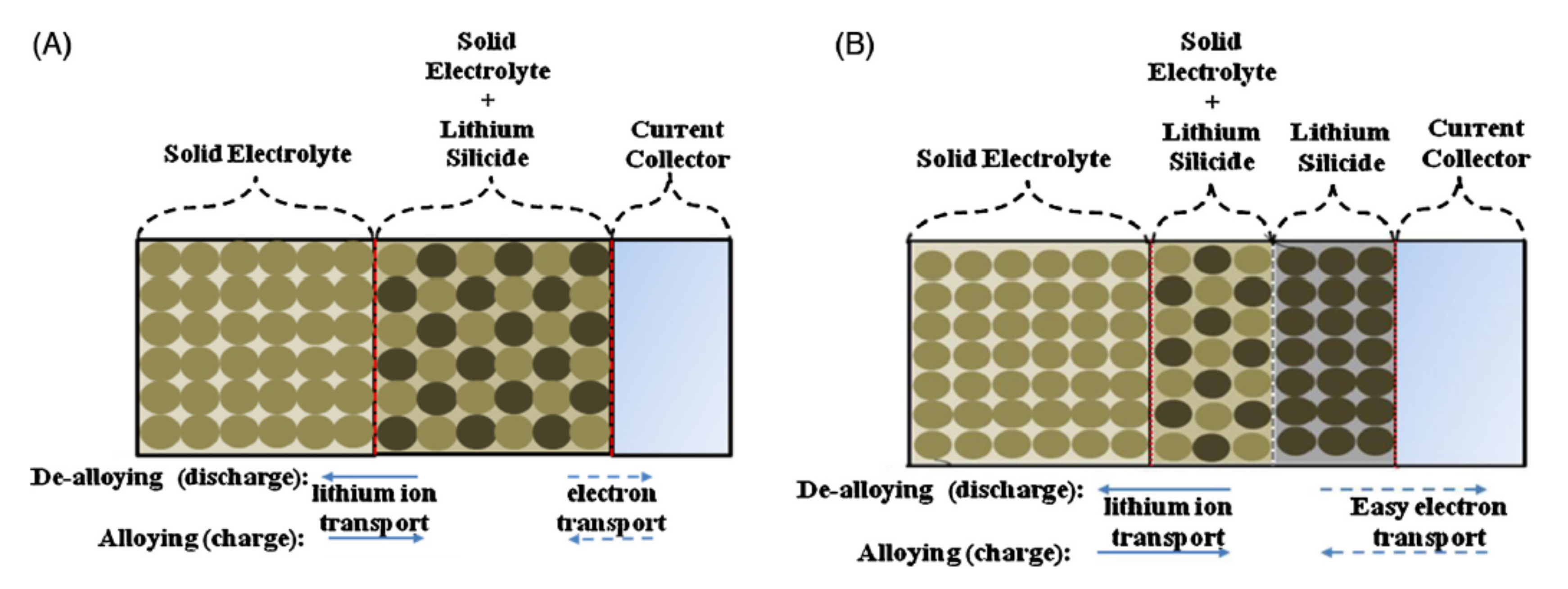
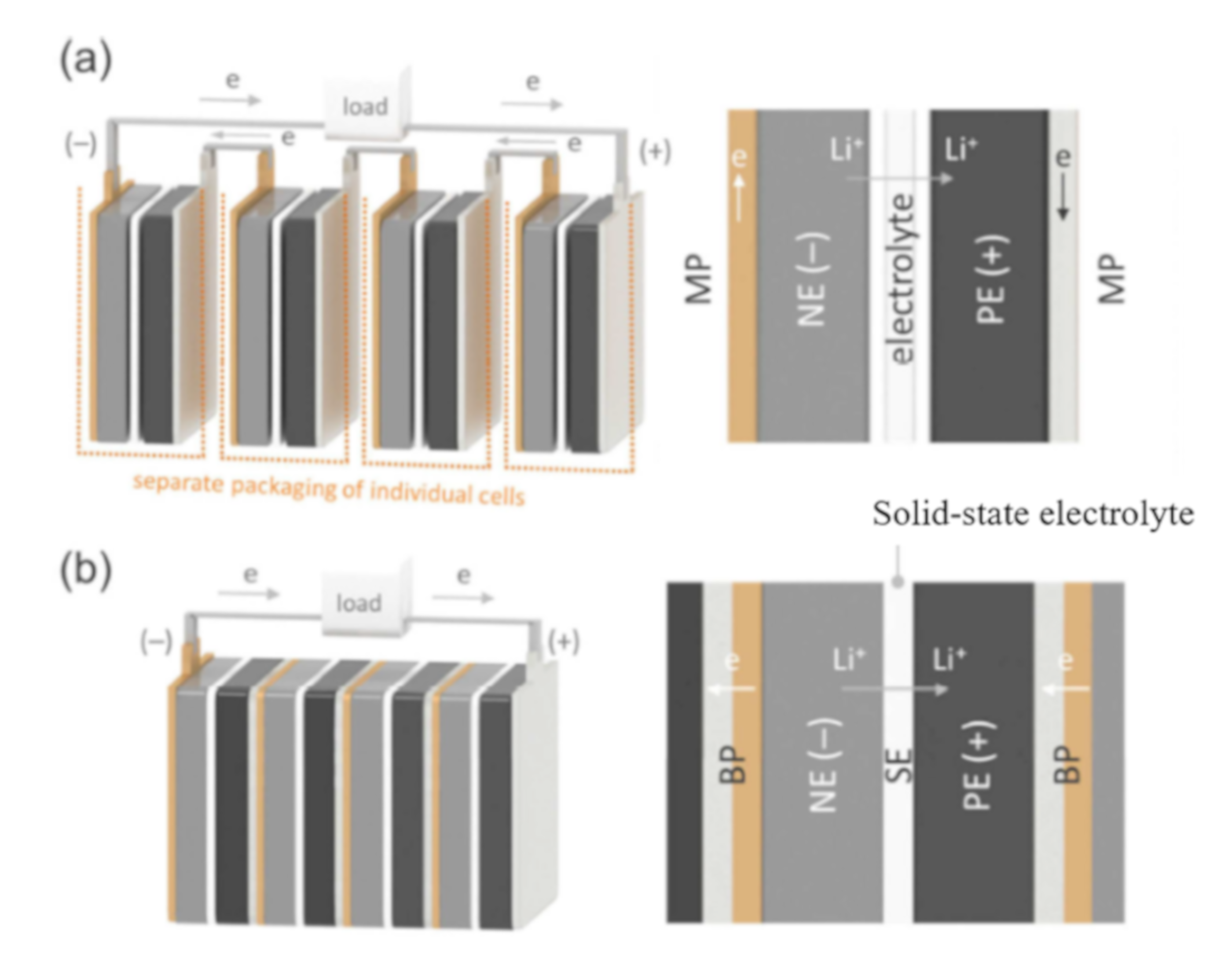
7. CCs for All Solid-State LIBs

Owing to the safety issues of LIBs, geometric restrictions related to the electrolyte and inhibition of the formation of Li dendrites, which are solid-state electrolytes, have been extensively examined. Kanno reported the development of high-power all-solid-state batteries using sulfide-based solid electrolytes [8]. Since his results were reported, research in this area has developed rapidly [121,122,123]. The possibility of realizing high-power, all-solid-state batteries by 2030 has been raised [124]. The application of solid-state electrolytes to sodium batteries has also been reported in many papers [125,126,127,128].
The properties needed for CCs in all-solid-state LIBs are dependent on the materials and preparation methods used. In the case of the simplest type of solid-state LIB, an active material powder, a solid electrolyte powder, and a conductive powder are pressed together to make active material layers for the anode or cathode, and then a solid-electrolyte layer is formed with the powder. Finally, the active material powder, solid electrolyte powder, and conductive powder are pressed together again to make active material layers for the anode or cathode. The process is performed with a dry mixing and pressing method. Planar Al and Cu foils used in conventional liquid LIBs are used as CCs for cathodes and anodes [121]. On the other hand, to decrease the contact resistance between the CC and cathode or anode active materials, CNT sheets can be fabricated as CCs and placed between the active materials and battery case materials (Figure 14), resulting in a reversible capacity and high-rate discharge performance in the resulting all-solid-state LIBs [129]. A copper-coated carbon fiber was used to make a poly(ethylene oxide) (PEO)-based polymer nanocomposite for a flexible and conductive CC layer in organic all-solid-state LIBs for wearable electronics in textile applications [130].
When all-solid-state LIBs are fabricated through the sequential growth of several layers, a high temperature is required during or after deposition for proper crystallization. Therefore, CCs must have a high temperature stability, as well as corrosion resistance, electrochemical stability, and inertness to lithium. Cr2N was proposed as a thermally stable CC by Buecheler and coworkers [131]. Cr2N has good mechanical properties, a low resistivity of ~1.1 x 10⁻⁴ Ω cm, and a high thermal stability in vacuum up to 1120 °C. In a study, a Cr2N layer was deposited on stainless steel, Al, and Si substrates by reactive pulsed DC sputtering. Thin films of LixMn1.5Ni0.5O4 deposited on the Cr2N layer exhibited electrochemical stability in the potential range from 3 to 5 V vs. Li+/Li. For the same reason, an Ni–Al–Cr alloy was also applied to solid-state LIBs as a high-temperature cathode CC [132].
In all-solid-state LIBs, Li metal is used as the anode because the solid-state electrolyte can prohibit the growth of Li dendrites [133]. Cathode layers are composed of cathode particles, solid-state electrolyte particles, and conductive additives (or a binder when necessary) by mixing the particles and pressing the layer. The use of dense cathode layers is not only beneficial for a high volumetric energy density but also a prerequisite for intimate interfacial contact and fast Li+ conduction [134]. Solid-state electrolytes contact the CC at the cathode. Therefore, CC selection is important for the performance of all-solid-state LIBs. Solid-state electrolytes are classified into two types: oxide-based and sulfide-based [133]. The CCs used in each type of solid-state electrolyte are summarized in the following section.
Oxide-based solid electrolytes include garnet, perovskite, Li2+2xZn1−xGeO4 and Na1+xZr2SixP3−xO12. For the garnet type (Li7LaZr2O12—LLZO), LLZO has attained particular importance due to its high lithium ion conductivity (~10−3 S cm−1), electrochemical stability against lithium metal, and wide electrochemical window (>5 V) [135]. However, the interfacial resistance between the electrodes and the electrolyte is very high. Therefore, for example, an Li metal|interlayer|LLZO|interlayer|cathode cell is usually constructed. Polymer electrolytes, such as a PEO-containing LiTFSI salt, have been used as the interlayer [136]. In this case, LiFePO4 cathode particles, PEO, a PVdF binder, and carbon black were components of the cathode layer. The cathode layer was formed on an Al foil CC. Additionally, in the case of composite electrolytes of LLZO and PEO, Al foil was used as a cathode CC [137]. Moreover, in the perovskite electrolyte Li3xLa2/3−xTiO3 (0 < x < 0.16—LLTO), to decrease the interfacial resistance between the electrolyte and active materials and to inhibit the redox reaction of the component in the electrolyte at the electrodes, polymer electrolyte layers were inserted between the LLTO and electrodes. The cathode layers were fabricated with Li+-conductive polymer materials on an Al CC [138]. A stainless steel plate, Al foil, and Al mesh were also employed as CCs for the cathode layer composed of the cathode material and the NASICON-type (LiM2(XO4)3, M = Ge, Ti, Zr, X = S, P, As) [139] and LISICON-type (Li2+2xZn1−xGeO4) electrolytes [140,141].
Li2S−P2S5 (Li7P3S11) is a sulfide-based glass ceramic that has a 3D framework structure, a 1D Li+ conduction path along the c-axis, and a high ionic conductivity of 10−3−10−4 S cm−1. A major disadvantage of Li2S−P2S5 electrolytes is that they tend to generate poisonous H2S gas when exposed to ambient air [133]. In LIBs fabricated with Li2S–P2S5 (Li7P3S11) electrolytes and their analogs, stainless steel and Ti were used as CCs [142,143]. To improve the electrode reaction, the modification of the interface between the anode layer and CC surface was proposed to improve the electron and Li+ ion transport in the anode layer and the interface [144]. Lim et al. proposed the construction of a gradient-structured anode layer composed of a lithium silicide anode and Li2S–P2S5 electrolyte. The gradient-structured anode layer consisted of a lithium silicide/solid electrolyte composite layer (for easy lithium ion transport from the anode to the electrolyte and vice versa) and a lithium silicide layer (for easy electron transport from the anode to the CC and vice versa) (Figure 15). They reported that the cell with the gradient-structured anode also showed two-to-three-fold higher capacities than a cell with a conventional electrode design [144].
There are many papers on CCs in organic solid-state LIBs [145]. In contrast with liquid LIBs, the anodic dissolution of Al CCs at high voltages does not form an AlF3/LiF passivation film on the Al surface in LIBs prepared with polymer electrolytes. Inhibition salts should be added to polymer electrolytes. For example, an AlF3/LiF passivation film on an Al surface cannot be formed due to the salts in imide salt−polymer plastic crystal electrolytes, which limits their application in high-voltage organic solid-state LIBs. It was found that an optimized concentration of LiTFSI in imide salt−polymer plastic crystal electrolytes can suppress anodic Al dissolution [146]. Though a perfluoropolyether-based polymer electrolyte is not a solid-state electrolyte and is a liquid electrolyte, it can effectively inhibit the corrosion of Al CCs and suppress lithium dendrite growth [147].
In Table 1, CCs used in all-solid-state LIBs are summarized with active materials, electrolytes, and operation voltage ranges. In the research of solid-state electrolytes, the selection of CC materials is just getting started. The materials that do not react with electrolytes used in cells were just selected among conventional CCs, such as Al, Cu, Ni, stainless steel, and carbon. Many researchers and engineers cannot yet turn their attention towards high-functioning CCs, such as 3D structures, because safety issues are paramount.
Bipolar LIBs have a bipolar design in which unit (mono) cells are in direct contact with each other and connected in series in a battery module without using external electrical connections between them (Figure 16) [148]. Therefore, the reduction of the volumetric percentage of the CC and exterior material in an LIB allows for the energy density of the battery to be improved [148,149]. In particular, this design can be realized with solid-state electrolytes because they do not have fluidity and can completely isolate each bipolar electrode in an LIB cell. Because research on solid-state electrolytes has become very active and the possibility of realizing high-power all-solid-state batteries has been raised, the development of bipolar LIBs with solid-state electrolytes has recently attracted the attention of researchers as a way to improve battery performance [150,151,152,153]. CCs for bipolar LIBs must have electrochemical stability under the operating conditions for both the anode and the cathode, as well as a high electron conductivity and an excellent adhesion to the anode and cathode layers. Various types of metals and alloys have been proposed for CCs for bipolar LIBs. In a review paper on bipolar solid-state LIBs, Lee and Park summarized the advantages and disadvantages of bipolar LIB CCs consisting of materials such as Al, Cu, Ni, and stainless steel [150]. Unno et al. reported that stainless steel can be applied as a CC in bipolar LIBs. The anode and cathode layers were coated on each side of a stainless steel foil because of the large voltage window of stainless steel. Stable charge/discharge cycles were observed in the laminated bipolar cell. Though stainless steel has a higher electron resistance than Al, Cu, and Ni, this disadvantage of stainless steel as a CC can be recovered by combining stainless steel CCs with bipolar LIBs [96]. As another characteristic example, a clad metal of Cu/Al composed of bonded Cu and Al foils was proposed as a CC for bipolar LIBs. The Cu side of the Cu/Al clad contacted the cathode layer, and an anode layer was formed on the Al side. The clad CC does not need electrochemical stability over a wide potential range and only has to function as a cathode or an anode on each side [152].
If the application of solid-state electrolytes to batteries is established at a practical level, the design of batteries will definitely change from monopolar to bipolar types. In that case, CCs with electrochemical stability over the operating voltages for anodes and cathodes and that are cost-effective and have chemical stability against solid-state electrolytes should be developed soon.

8. CCs for Post-LIBs

Many researchers and engineers worldwide have expended much effort to study the development of post-LIBs such as sodium (Na)-ion and Na metal, magnesium (Mg)-ion and Mg metal, calcium (Ca)-ion and Ca metal, and Al-ion and Al metal batteries, all of which can overcome the weaknesses of LIBs such as low battery performance, high-cost, the low natural abundance of Li, and battery safety issues. These batteries also have many problems to be resolved before their commercialization. Many materials and technologies have been examined and developed [154,155,156]. According to the materials and operating conditions in batteries, CCs must be able to change their properties and shape and should have modifications on their surface. The materials and properties of CCs used in batteries and the methods to modify their surfaces are summarized with regard to the type of battery as follows.

8.1. Na-Ion and Na Metal Batteries

Na-ion and Na metal batteries are representative of post-LIBs because Na metal has a high theoretical specific capacity (1165 mAh g−1) and a standard redox potential of −2.71 V (vs. SHE), and the Na resource has characteristics such as a high relative abundance in Earth’s upper continental crust. Therefore, the Na-ion and Na metal batteries have a high energy density and a low cost [157,158]. Many studies have been performed [157,158]. Similar to LIBs, in Na-ion batteries, Na+ ions intercalate and deintercalate to/from compounds of NaCoO2 and Na2Ti3O7 as the cathode and anode materials, respectively. Na-ion batteries have a cell voltage of 3.1 V [159]. In LIBs, less expensive Al CCs are used only as cathode CCs because Al forms an alloy with Li. Na-ion batteries can replace Cu CCs in anodes with less expensive Al CCs [159].
In many papers on CCs for Na metal batteries, the prohibition of Na dendrite growth, which is more problematic than Li dendrite growth, has been evaluated. Porous Al and Cu CCs [160,161], carbon felt [162], conducting polymer paper-derived mesoporous 3D N-doped carbon [163], and prepatterned [164] CCs have been proposed, as mentioned in the section on Li dendrite inhibition. A PVdF coating on the Cu CC surface was also examined to prohibit uncontrollable Na dendrite growth during the repetitive Na deposition/stripping process [165]. Additionally, in Na-ion and Na metal batteries, the stability of Al CCs is the key issue to guarantee the safety of batteries. An example of the application of sodium bis(fluorosulfonyl)imide (NaFSI) to propylene PC and N-propyl-N-methylpyrrolidinium bis(fluorosulfonyl)imide (C3C1pyrrFSI) reported that no evidence of anodic Al dissolution was detected after 50 cycles [166].

8.2. Mg-Ion and Mg Metal Batteries

Mg-ion and Mg metal batteries have attracted increasing attention because these batteries can realize low-cost and high energy density devices with improved safety, which remain bottlenecks in the development of LIBs [167]. The key characteristics of Mg-ion and Mg metal batteries are the much lower cost of Mg metal; it costs 24 times less than Li metal and has a superior safety because it is air-stable and because Mg ions can be deposited onto Mg metal without the formation of dendritic structures [168]. The key factor for rechargeable Mg metal batteries is the development of electrolyte solutions that exhibit the reversible electrochemical deposition of Mg on the Mg metal anode and the dissolution of Mg2+ from the Mg metal anode as well as a large voltage window, compatibility with metallic Mg, and a high ionic conductivity. The electrolytes for Mg batteries can cause the severe corrosion of CCs made from conventional Cu, Al, Ti, and stainless steel. In the early stage of research on electrolytes for Mg batteries, Aurbach et al. demonstrated electrolytes with an anodic stability of ~2.5 V by reacting Grignard reagents (MgR2, R = ethyl and butyl) with aluminum-based Lewis acids (AlEtCl2 or AlCl3) [169]. An electrolyte containing high concentrations of chloride anions is corrosive to almost all of the investigated metals and alloys. Several attempts to find stable CCs for electrolytes of Mg batteries have been reported [170,171,172]. In the case of an electrolyte of 1 M magnesium bis(hexamethyldisilazide)–AlCl3 (molar ratio 1:2), an excellent corrosion resistance was observed for Inconel 625 (Ni 61%, Cr 22%, Fe < 5%, Mo 9%) and Hastelloy B (Ni 62%, Mo 27%, Fe 5%, Cr 0.8%, Mn 0.6%, Si 0.5%) [170]. Ni was found to exhibit an excellent stability up to 2.2 V (vs. Mg2+/Mg) in a Mg(AlCl2EtBu)2/tetrahydrofuran (THF) electrolyte [171]. The glassy carbon coating on Ti and stainless steel CCs by plasma carburization was developed to impart the CC surfaces with anticorrosion properties, using a THF solution containing 0.50 M phenylmagnesium chloride and 0.25 M AlCl3 [172]. In high-voltage magnesium–lithium hybrid batteries using dual-salt electrolytes, molybdenum metal was used as a CC in 0.2 M [Mg2Cl2(DME)4][AlCl4]2 and 1.0 M LiTFSI (DME = dimethoxyethane)-based electrolytes [173].

8.3. Ca-Ion and Ca Metal Batteries
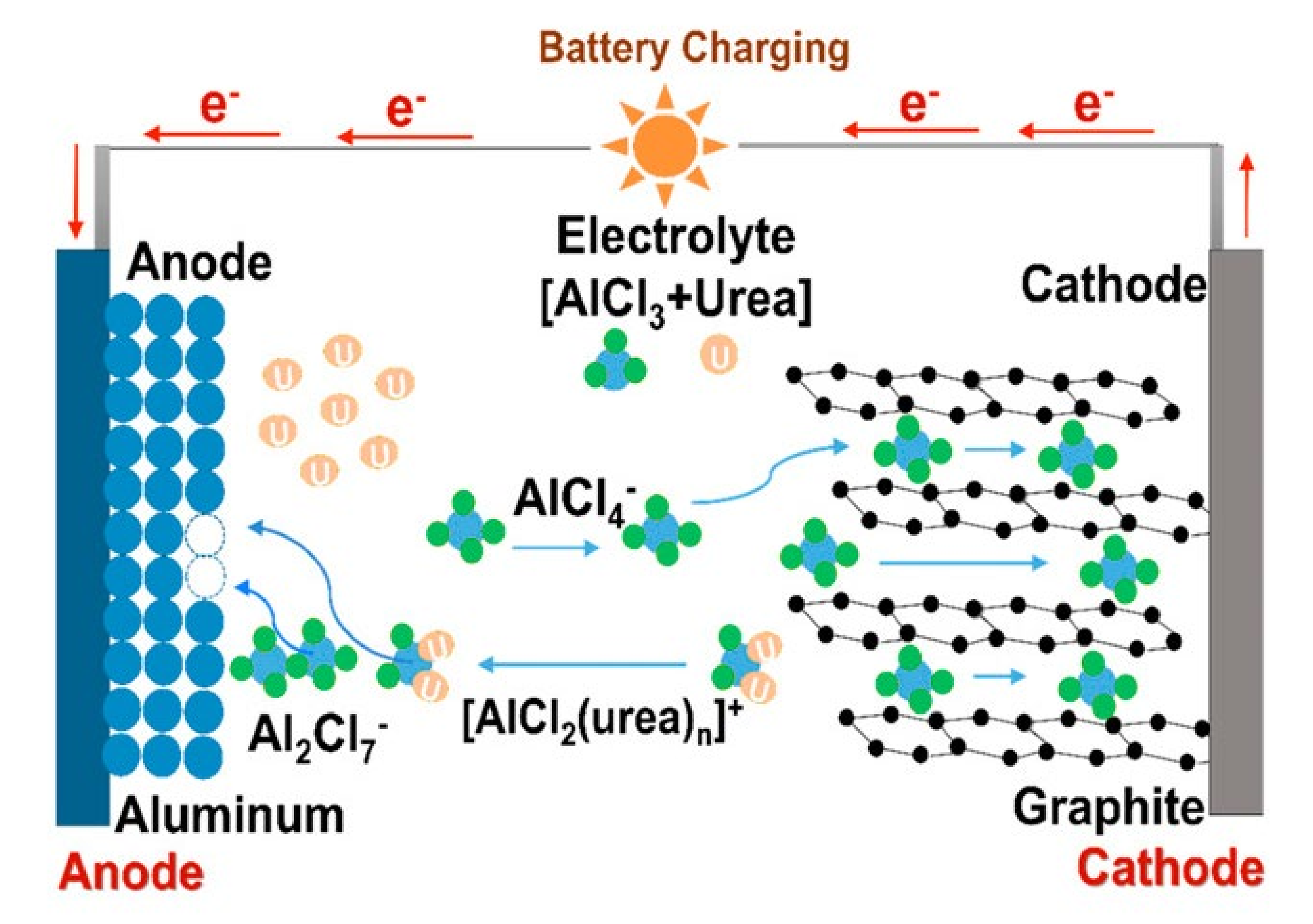
Ca is also an interesting candidate because it is abundant and has a lower standard potential than Mg by ~0.5 V and a higher atomic weight than Li; moreover, two electrons per Ca atom can be stored. Therefore, Ca theoretically delivers a high capacity of 1340 mAh g−1. In addition, Ca is nontoxic and therefore does not pose an environmental hazard [174,175]. The number of papers on Ca-ion and Ca batteries is very low, and there are few papers on CCs for Ca-ion and Ca batteries. Relevant papers have described the corrosion of CCs, depending on the kind of CC and composition of electrolytes similar to other batteries. Ingram et al. examined the electrochemical stability of stainless steel and graphite foil in a 0.1 M calcium triflate (Ca(OTf)2) and 1 M tetra-n-butylammonium triflate (TBA(OTf))/dimethylformamide (DMF) electrolyte, and they found that the corrosion of stainless steel in the electrolytes was catalyzed by transition metal oxides and/or carbon black and that graphite foil did not show any corrosion behavior [176]. In a TiS2 cathode involving a cation-solvated intercalation mechanism and 0.3 M Ca(TFSI)2/PC, 316 stainless steel could exhibit reversible, stable intercalation/deintercalation reactions at room temperature [177]. The battery was composed of a CaSi2 cathode and an electrolyte of 0.45 MCa(BF4)2/ethylene carbonate:PC (50/50 wt.%) with Al CCs [178]. The mixed layer of MoO3, carbon black, and PVdF was deposited on Ti foil to prepare a cathode. The resulting experimental reversible capacity was approximately 80–100 mAh g−1, and the average voltage was approximately 1.3 V vs. Ca [179].

8.4. Al Batteries

Al is both an abundant and relatively inexpensive metal. The theoretical capacity of Al is 2980 mAh g−1 [180], and the standard redox potential of Al (−1.7 V vs. SHE) is more positive than that of Li (−3.05 V vs. SHE), leading to a lower cell voltage. Recently, Al-graphite dual ion batteries have attracted a substantial amount of attention because these batteries have been found to exhibit a graphite cathode specific capacity of ~70 mAh g−1 with a Coulombic efficiency (CE) of 97%–98% and ultrahigh charge/discharge rate (up to 5000 mA g−1) for over 7000 cycles [181]. An Al battery system operates based on the reversible deposition/stripping of Al at the anode and the reversible intercalation/deintercalation of chloroaluminate anions at the graphite cathode in an EMIC-AlCl3 ionic liquid electrolyte (Figure 17). Conventional CCs typically used in other batteries, such as Cu, stainless steel and Ni, cannot be used due to the corrosion that occurs in EMIC-AlCl3 electrolytes. In particular, when electrolytes comprising acidic ionic liquids with Al2Cl7 are used, they are very corrosive to CCs. Electrochemically inert foils, such as W [182], Mo [183] and anticorrosive titanium nitride (TiN)-coated stainless steel [41], were applied as CCs to Al-graphite dual ion batteries. However, Ventosa et al. calculated the contribution of each component to the purchase price of Al-ion batteries and mentioned that the main contributor to the cost is the W substrate used as the cathode CC [184,185]. The expensive W CC should be replaced by other low-cost CC materials. Because the specific energy density of currently available Al batteries at the pack level is far below that of LIBs (~180 W h kg−1) [185], a reduction in the volume and weight of inactive materials, such as CCs, in batteries can directly improve their energy density. Low-cost, lightweight carbon fibers [186], cloth [187], and biomass-derivative carbon [188] have been considered. These porous structures as CCs can offer an effective electrical transportation network and a buffer space to shorten the ion diffusion path, and they can provide sufficient mechanical strength against the strain and stress caused by the large volume change of graphite cathodes. Ventosa et al. mentioned that all carbon-based materials cannot be applied as CCs for Al batteries. As CCs, although a certain graphitic character is required in the carbon material to provide sufficient electrical conductivity, materials working as CCs should not be too graphitic because the CCs may become electrochemically active, hosting anions and leading to volumetric changes, which results in the active materials detaching from the cathode electrode and a large decrease in the capacity. Both graphitic and amorphous carbon materials are potential candidates [184].

8.5. Sulfur Batteries

Studies on Li-, Na-, and Mg-ion batteries in which sulfur is used as an active material in the cathode have been carried out in recent years because sulfur has a low environmental impact, is naturally abundant as a rather inexpensive byproduct of the desulfurization of crude oil, and has a specific capacity as high as 1672 mA hg−1 [189,190,191,192]. In sulfur cathodes exhibiting lower charge/discharge voltages than those of conventional cathode materials, such as LiCoO2, LiMn2O4, and LiFePO4, the Al cathode CC is replaced by a Cu CC, which is less expensive than Al [193,194,195,196,197]. The effect of the CC on the performance of a sulfur cathode is very well known. An increased stability and rate capability of sulfur cathodes can be achieved with Cu CCs. Lu et al. reported that the exposure of a Cu CC to polysulfide in aqueous or aprotic solutions to prepare a sulfidized Cu CC and the employment of that CC for sulfur cathodes produced specific capacities up to ≈1200 mAh g−1 for Li–S batteries and ≈400 mAh g−1 for Na–S batteries when normalized to the amount of equivalent sulfur; additionally, operation could be readily sustained for >1000 cycles [193]. On the Cu CC surface, polysulfide, whose outflow and shuttling lead to reduced cycle life and stability, was trapped via weak physical confinement and interfacial chemical interactions with the Cu surface. The formation of a Cu2S nanoflake array with a tunable texture and thickness was considered [193]. A nitrogen- and sulfur-doped carbon cloth used as a cathode CC was also developed to prohibit the outflow of polysulfides based on the chemical interaction between magnesium polysulfide and the N/S dual-doped carbon cloth to improve the cycle life [194]. On the other hand, several results have suggested that Cu should not be used as a CC for sulfur cathodes because its capacity observed in the charge/discharge cycles is reduced and because the Cu CCs are unstable and do not have anticorrosion properties [195,196,197]. Further examinations and discussions on suitable CCs for sulfur cathodes are needed.
In Table 2, CCs used in post-LIBs are summarized with active materials, electrolytes, and operation voltage ranges. Corrosion caused by electrolytes in post-LIBs is a serious problem for the widespread use of these batteries. The corrosion of CCs by corrosive electrolytes can possibly be inhibited by selecting new CC materials or by modifying the CC surfaces; improvements are required because the corrosive electrolytes are extremely dangerous when they leak from batteries. In our opinion, CCs that are able to withstand exposure to corrosive electrolytes and not be damaged are unlikely to be developed. Thus, corrosive electrolytes should be replaced with noncorrosive electrolytes.

9. Conclusions and Perspectives

In this review, we systematically summarized the CCs and discussed their potential advantages and disadvantages for the development of high-performance batteries. The CCs in batteries are ignored and viewed as problematic to some extent because CCs cannot store electricity and are one of the factors causing a decrease in the energy density of a cell. Nevertheless, recently, many papers on CCs have been reported. Thus, as we have reviewed in this paper, many researchers and engineers perceive the importance of the functions of CCs in batteries.
First, CCs in batteries should have favorable physical, chemical, and electrochemical properties, such as anticorrosion properties against the electrolytes used, electrochemical stability against high applied potentials, high mechanical strength, excellent adhesion to the active material layers, light weightedness, and cost effectiveness. As a result of substantial effort, changing the materials for CCs and electrolytes, modifying the CC surface, and establishing 3D structures of active material layers with CCs have been accomplished. Here, we provide some perspectives based on our understanding.
(1)
To provide anticorrosion properties and a wide potential window for CCs, stainless steel and Ni, which are costly and have complicated coating processes, should not be employed. In contrast, additives that can be added to electrolytes should be developed because they can adsorb onto CC surfaces and form protective layers to inhibit corrosion and electrochemical dissolution at higher potentials. The employment of additives may avoid an increase in the number of processes in the LIB fabrication process. We should turn our attention towards the development of additives that can easily form a desirable surface layer.
(2)
Many 3D CC structures that contain thick electrodes and produce a cell with a high energy density have been proposed in many papers and have been found to exhibit excellent battery performance. To achieve 3D anodes and cathodes with 3D CCs in commercially available batteries, the mass production of 3D anodes and cathodes is fundamentally required. The recent fabrication of 3D structures with lasers may shed light on solving the problem [198]. Laser processes for cutting, annealing, structuring, and printing battery materials that show great potential for battery mass production have been developed to minimize fabrication costs and to increase the electrochemical performance and operational lifetime of batteries. It is especially important to develop highly scalable methods by shortening laser processing time.
(3)
In currently available LIBs, Cu and Al CCs are used because of their light weight, low cost, and chemical and electrochemical stability. In the future, it will be highly necessary for CCs to be composed light materials, and the content ratio of the CCs in a cell will need to be extremely close to zero. Recently, the words “free-standing” have often been seen in the titles of papers related to batteries. This term can refer to a CC-free or metal-free CC and carbon CCs. In addition, the number of papers researching carbon-based CCs has recently increased. Highly functional carbon materials are being applied to prepare CCs with high electron conductivity and anticorrosion properties. Carbon materials are good for the construction of 3D CCs that can produce thick anode and cathode layers and that improve the energy density of batteries. Additionally, in the area of flexible batteries, which will be demanded and progressively developed, carbon CCs will play an important role and realize the upcoming commercialization of flexible batteries as the power sources for wearable devices.
(4)
Three-dimensional anodes and cathodes are becoming increasingly important factors to remarkably improve battery performance. To date, 3D CCs can be formed with various strategies. However, the fabrication process of 3D anodes and cathodes with 3D CCs has not been developed. In current LIB fabrication processes, the anode and cathode are prepared by casting a slurry containing anode or cathode materials on planar CC surfaces and drying the slurry thin layer on the CC surface. However, in 3D anodes and cathodes with 3D CCs, dense anode and cathode layers cannot be formed without voids in the active material layers at the mass production level. To the best of our knowledge, coating machines for 3D CCs have not yet been developed. Thus, the development of coating machines is urgent.
(5)
To date, the development of all-solid-state batteries and post-LIBs is encouraging because dedicated research efforts are required to commercialize batteries. Conventional CCs are used for batteries. However, a deep examination of matching CCs and electrolytes for batteries has not yet been performed. As done in the case of organic liquids containing Li salts, the chemical and electrochemical stability of CCs should be analyzed with various experimental techniques. In particular, a discussion of the reaction of CCs with solid-state electrolytes is insufficient. The data regarding CCs for solid-state electrolytes should be published as soon as possible because the resistance between CCs and active material layers should be removed so that research on electron and Li+ transfers in the interface between active material surfaces and electrolytes can be conducted. After optimizing CCs for each battery, future research should focus on considering strategies to incorporate CCs into the mass production of all-solid-state batteries and post-LIBs.

Author Contributions

M.Y.: mainly the preparation of the manuscript; T.W.: the collection of papers and the categorization of papers for the preparation of the manuscript; T.G.: the preparation of figures, the collection of copyright permission, and checking English; J.W.: the preparation of Section 7 and Section 8, and checking English; F.M.: correction and rearrangement of manuscript. All authors have read and agreed to the published version of the manuscript.

Funding

This research received no external funding.

Conflicts of Interest

The authors declare no conflict of interest.

References

  1. Winter, M.; Barnett, B.; Xu, K. Before Li ion batteries. Chem. Rev. 2018, 118, 11433–11456. [Google Scholar] [CrossRef] [PubMed]
  2. Li, M.; Lu, J.; Chen, Z.; Amine, K. 30 years of lithium-ion batteries. Adv. Mater. 2018, 30, 1800561. [Google Scholar] [CrossRef] [Green Version]
  3. Zhao, H.; Xu, J.; Yin, D.; Du, Y. Electrolytes for batteries with earth-abundant metal anodes. Chem. Eur. J. 2018, 24, 18220–18234. [Google Scholar] [CrossRef]
  4. Nitta, N.; Wu, F.; Lee, J.T.; Yushin, G. Li-ion battery materials: Present and future. Mater. Today 2015, 18, 252–264. [Google Scholar] [CrossRef]
  5. Roy, P.; Srivastava, S.K. Nanostructured anode materials for lithium ion batteries. J. Mater. Chem. A 2015, 3, 2454–2484. [Google Scholar] [CrossRef]
  6. Goodenough, J.B.; Park, K.-S. The Li-ion rechargeable battery: A perspective. J. Am. Chem. Soc. 2013, 135, 1167–1176. [Google Scholar] [CrossRef]
  7. Yuan, M.; Liu, K. Rational design on separators and liquid electrolytes for safer lithiumion batteries. J. Energy Chem. 2020, 43, 58–70. [Google Scholar] [CrossRef] [Green Version]
  8. Kato, Y.; Hori, S.; Saito, T.; Suzuki, K.; Hirayama, M.; Mitsui, A.; Yonemura, M.; Iba, H.; Kanno, R. High-power all-solid-state batteries using sulfide superionic conductors. Nat. Energy 2016, 1, 16030. [Google Scholar] [CrossRef]
  9. Chen, H.; Ling, M.; Hencz, L.; Ling, H.Y.; Li, G.; Lin, Z.; Liu, G.; Zhang, S. Exploring chemical, mechanical, and electrical functionalities of binders for advanced energy-storage devices. Chem. Rev. 2018, 118, 8936–8982. [Google Scholar] [CrossRef]
  10. Yang, Z.; Ren, J.; Zhang, Z.; Chen, X.; Guan, G.; Qiu, L.; Zhang, Y.; Peng, H. Recent advancement of nanostructured carbon for energy applications. Chem. Rev. 2015, 115, 5159–5223. [Google Scholar] [CrossRef]
  11. Ming, J.; Cao, Z.; Wu, Y.; Wahyudi, Y.; Wang, W.; Guo, X.; Cavallo, L.; Hwang, J.-Y.; Shamim, A.; Li, L.-J.; et al. New insight on the role of electrolyte additives in rechargeable lithium ion batteries. ACS Energy Lett. 2019, 4, 2613–2622. [Google Scholar] [CrossRef]
  12. Myung, S.-T.; Sasaki, Y.; Sakurada, S.; Sun, Y.-K.; Yashiro, H. Electrochemical behavior of current collectors for lithium batteries in non-aqueous alkyl carbonate solution and surface analysis by ToF-SIMS. Electrochim. Acta 2009, 55, 288–297. [Google Scholar] [CrossRef]
  13. Bard, A.J.; Parsons, R.; Joedan, J. Standard Potentials in Aqueous Solutions, International Union of Pure and Applied Chemistry; Marcel Dekker, Inc.: New York, NY, USA, 1985. [Google Scholar]
  14. Dai1, S.; Chen, J.; Ren, Y.; Liu, Z.; Chen, J. Electrochemical corrosion behavior of the copper current collector in the electrolyte of lithium-ion batteries. Int. J. Electrochem. Sci. 2017, 12, 10589–10598. [Google Scholar] [CrossRef]
  15. Chen, J.; Li, C.; Zhang, J.; Li, C.; Chen, J.; Ren, Y. First-principles study on the adsorption and dissociation of impurities on copper current collector in electrolyte for lithium-ion batteries. Materials 2018, 11, 1256. [Google Scholar] [CrossRef] [Green Version]
  16. Fear, C.; Juarez-Robles, D.; Jeevarajan, J.A.; Mukherjee, P.P. Elucidating copper dissolution phenomenon in Li-ion cells under overdischarge extremes. J. Electrochem. Soc. 2018, 165, A1639–A1647. [Google Scholar] [CrossRef]
  17. Onodera, S.; Kato, N.; Ito, T.; Ito, T.; Tachibana, K.; Nishina, N. The Effect of dispersion degree of positive electrodes containing carbon nanotubes with identical composition on contact resistance in lithium ion secondary batteries. Electrochemistry 2015, 83, 386–388. [Google Scholar] [CrossRef]
  18. Honda, C.; Kikuchi, S.; Ito, T.; Onodera, S.; Nagai, A.; Ito, T.; Tachibana, K.; Nishina, T. Evaluation of contact resistance of aluminum current collector surfaces for energy storage systems. Electrochemistry 2014, 82, 328–330. [Google Scholar] [CrossRef] [Green Version]
  19. Wu, H.-C.; Wu, H.-C.; Lee, E.; Wu, N.-L. High-temperature carbon-coated aluminum current collector for enhanced power performance of LiFePO4 electrode of Li-ion batteries. Electrochem. Commun. 2010, 12, 488–491. [Google Scholar] [CrossRef]
  20. Myung, S.-T.; Yashiro, H.; Sun, Y.-K. Electrochemical behavior and passivation of current collectors in lithium-ion batteries. J. Mater. Chem. 2011, 21, 9891–9911. [Google Scholar] [CrossRef]
  21. Streipert, B.; Röser, S.; Kasnatscheew, J.; Janßen, P.; Cao, X.; Wagner, R.; Cekic-Laskovic, I.; Winter, M. Influence of LiPF6 on the aluminum current collector dissolution in high voltage lithium ion batteries after long-term charge/discharge experiments. J. Electrochem. Soc. 2017, 164, A1474–A1479. [Google Scholar] [CrossRef]
  22. Ma, T.; Xu, G.-L.; Li, Y.; Wang, L.; He, X.; Zheng, J.; Liu, J.; Engelhard, M.H.; Zapol, P.; Curtiss, L.A.; et al. Revisiting the corrosion of the aluminum current collector in lithium-ion batteries. J. Phys. Chem. Lett. 2017, 8, 1072–1077. [Google Scholar] [CrossRef]
  23. Sayed, F.N.; Rodrigues, M.-T.F.; Kalaga, K.; Gullapalli, H.; Ajayan, P.M. Curious case of positive current collectors: Corrosion and passivation at high temperature. ACS Appl. Mater. Interfaces 2017, 9, 43623–43631. [Google Scholar] [CrossRef]
  24. Ni, S.; Li, T.; Lv, X.; Yang, X.; Zhang, L. Designed constitution of NiO/Ni nanostructured electrode for high performance lithium ion battery. Electrochim. Acta 2013, 91, 267–274. [Google Scholar] [CrossRef]
  25. Yao, M.; Okuno, K.; Iwaki, T.; Kato, M.; Tanase, S.; Emura, K.; Sakai, T. LiFePO4-based electrode using micro-porous current collector for high power lithium ion battery. J. Power Sources 2007, 173, 545–549. [Google Scholar] [CrossRef]
  26. Song, K.Y.; Jang, G.S.; Tao, J.; Lee, J.H.; Joo, S.K. Influence of conductive carbon content using a three-dimensional foam-type current collector for lithium ion battery. J. Electrochem. Soc. 2016, 163, A2981–A2987. [Google Scholar] [CrossRef]
  27. Kang, C.W.; Choi, J.; Ko, Y.-J.; Lee, S.M.; Kim, H.J.; Kim, J.P.; Son, S.U. Thin coating of microporous organic network makes a big difference: Sustainability issue of Ni electrodes on the PET textile for flexible lithium-ion batteries. ACS Appl. Mater. Interfaces 2017, 9, 36936–36943. [Google Scholar] [CrossRef]
  28. Liu, L.-J.; Chen, Y.; Zhang, Z.-F.; You, X.-L.; Walle, M.D.; Li, Y.-J.; Liu, Y.-N. Electrochemical reaction of sulfur cathodes with Ni foam current collector in Li-S batteries. J. Power Sources 2016, 325, 301–305. [Google Scholar] [CrossRef]
  29. Furukawa, K.; Yoshimoto, N.; Egashira, M.; Morita, M. Anodic behavior of stainless-steel substrate in organic electrolytesolutions containing different lithium salts. Electrochim. Acta 2014, 140, 125–131. [Google Scholar] [CrossRef]
  30. Myunga, S.-T.; Sasaki, Y.; Saito, T.; Sun, Y.-K.; Yashiro, H. Passivation behavior of Type 304 stainless steel in a non-aqueous alkyl carbonate solution containing LiPF6 salt. Electrochim. Acta 2009, 54, 5804–5812. [Google Scholar] [CrossRef] [Green Version]
  31. Shironita, S.; Ihsan, N.; Konakawa, K.; Souma, K.; Umeda, M. Investigation of nitriding treated Ni-free stainless steel as current collector for 5 V-class Li-ion secondary cell. Electrochim. Acta 2019, 295, 1052–1056. [Google Scholar] [CrossRef]
  32. Aliahmad, N.; Liu, Y.; Xie, J.; Agarwal, M. V2O5/graphene hybrid supported on paper current collectors for flexible ultrahigh-capacity electrodes for lithium-ion batteries. ACS Appl. Mater. Interfaces 2018, 10, 16490–16499. [Google Scholar] [CrossRef] [Green Version]
  33. Wang, C.-C.; Lin, Y.-C.; Chiu, K.-F.; Leu, H.-J.; Ko, T.-H. Advanced carbon cloth as current collector for enhanced electrochemical performance of lithium-rich layered oxide cathodes. ChemistrySelect 2017, 2, 4419–4427. [Google Scholar] [CrossRef]
  34. Martha, S.K.; Dudney, N.J.; Kiggans, J.O.; Nanda, J. Electrochemical stability of carbon fibers compared to aluminum as current collectors for lithium-ion batteries. J. Electrochem. Soc. 2012, 159, A1652–A1658. [Google Scholar] [CrossRef]
  35. Cui, L.-F.; Hu, L.; Choi, J.W.; Cui, Y. Light-weight free-standing carbon nanotube-silicon films for anodes of lithium ion batteries. ACS Nano 2010, 4, 3671–3678. [Google Scholar] [CrossRef]
  36. Hu, J.W.; Wu, Z.P.; Zhong, S.W.; Zhang, W.B.; Suresh, S.; Mehta, A.; Koratkar, N. Folding insensitive, high energy density lithium-ion battery featuring carbon nanotube current collectors. Carbon 2015, 87, 292–298. [Google Scholar] [CrossRef]
  37. Wang, K.; Wu, Y.; Wu, H.; Luo, Y.; Wang, D.; Jiang, K.; Li, Q.; Li, Y.; Fan, S.; Wang, J. Super-aligned carbon nanotube films with a thin metal coating as highly conductive and ultralight current collectors for lithium-ion batteries. J. Power Sources 2017, 351, 160–168. [Google Scholar] [CrossRef]
  38. Whitehead, A.H.; Schreiber, H. Current collectors for positive electrodes of lithium-based batteries. J. Electrochem. Soc. 2005, 152, A2105–A2113. [Google Scholar] [CrossRef]
  39. Iwakura, C.; Fukumoto, Y.; Inoue, H.; Ohashi, S.; Kobayashi, S.; Tada, H.; Abe, H. Electrochemical characterization of various metal foils as a current collector of positive electrode for rechargeable lithium batteries. J. Power Sources 1997, 68, 301–303. [Google Scholar] [CrossRef]
  40. Wang, S.; Kravchyk, K.V.; Filippin, A.N.; Widmer, R.; Tiwari, A.N.; Buecheler, S.; Bodnarchuk, M.I.; Kovalenko, M.V. Overcoming the high-voltage limitations of Li-ion batteries using a titanium nitride current collector. ACS Appl. Energy Mater. 2019, 2, 974–978. [Google Scholar] [CrossRef] [Green Version]
  41. Wang, S.; Kravchyk, K.V.; Filippin, A.N.; Müller, U.; Tiwari, A.N.; Buecheler, S.; Bodnarchuk, M.I.; Kovalenko, M.V. Aluminum chloride-graphite batteries with flexible current collectors prepared from earth-abundant elements. Adv. Sci. 2018, 5, 1700712. [Google Scholar] [CrossRef]
  42. Jeong, C.U.; Lee, S.Y.; Kim, J.; Cho, K.Y.; Yoon, S. Embossed aluminum as a current collector for high-rate lithium cathode performance. J. Power Sources 2018, 398, 193–200. [Google Scholar] [CrossRef]
  43. Nakamura, T.; Okano, S.; Yaguma, N.; Morinaga, Y.; Takahara, H.; Yamada, Y. Electrochemical performance of cathodes prepared on current collector with different surface morphologies. J. Power Sources 2013, 244, 532–537. [Google Scholar] [CrossRef]
  44. Loghavi, M.M.; Askari, M.; Babaiee, M.; Ghasemi, A. Improvement of the cyclability of Li-ion battery cathode using a chemical-modified current collector. J. Electroanal. Chem. 2019, 841, 107–110. [Google Scholar] [CrossRef]
  45. Hang, T.; Nara, H.; Yokoshima, T.; Momma, T.; Osaka, T. Silicon composite thick film electrodeposited on a nickel micro-nanocones hierarchical structured current collector for lithium batteries. J. Power Sources 2013, 222, 503–509. [Google Scholar] [CrossRef]
  46. Long, J.; Liu, H.; Xie, Y.; Tang, W.; Fu, T.; Tang, Y.; Lu, L.; Ding, X.; Tang, X. Three-dimensional copper foil-powder sintering current collector for a silicon-based anode lithium-ion battery. Materials 2018, 11, 1338. [Google Scholar] [CrossRef] [Green Version]
  47. Choi, S.; Kim, T.-H.; Lee, J.-I.; Kim, J.; Song, H.-K.; Park, S. General approach for high-power Li-ion batteries: Multiscale lithographic patterning of electrodes. ChemSusChem 2014, 7, 3483–3490. [Google Scholar] [CrossRef]
  48. Kanamura, K. Anodic oxidation of nonaqueous electrolytes on cathode materials and current collectors for rechargeable lithium batteries. J. Power Sources 1999, 81, 123–129. [Google Scholar] [CrossRef]
  49. Meister, P.; Qi, X.; Kloepsch, R.; Kramer, E.; Streipert, B.; Winter, M.; Placke, T. Anodic behavior of the aluminum current collector in imide-based electrolytes: Influence of solvent, operating temperature, and native oxide-layer thickness. ChemSusChem 2017, 10, 804–814. [Google Scholar] [CrossRef]
  50. Armond, M.B.; Moursli, F. Bis Perhalogenoacyl -or Sulfonyl-Imides of Alkali Metals, Their Solid Solutions with Plastic Materials and Their Use to the Constitution of Conductor Elements for Electrochemical Generators. U.S. Patent 4,505,997, 19 March 1985. [Google Scholar]
  51. Dudley, J.T.; Wilkinson, D.P.; Thomas, G.; Le Vae, R.; Woo, S.; Blom, H.; Horvath, C.; Juzkow, M.W.; Denis, B.; Juric, P.; et al. Conductivity of electrolytes for rechargeable lithium batteries. J. Power Sources 1991, 35, 59–82. [Google Scholar] [CrossRef]
  52. Webber, A. Conductivity and viscosity of solutions of LiCF3SO3, Li(CF3SO2)2N, and their mixtures. J. Electrochem. Soc. 1991, 138, 2586–2590. [Google Scholar] [CrossRef]
  53. Kawamura, T.; Tanaka, T.; Egashira, M.; Watanabe, I.; Okada, S.; Yamaki, J. Methyl difluoroacetate inhibits corrosion of aluminum cathode current collector for lithium ion cells. Electrochem. Solid-State Lett. 2005, 8, A459–A463. [Google Scholar] [CrossRef]
  54. Oldiges, K.; Aspern, N.v.; Cekic-Laskovic, I.; Winter, M.; Brunklaus, G. Impact of trifluoromethylation of adiponitrile on aluminum dissolution behavior in dinitrile-based electrolytes. J. Electrochem. Soc. 2018, 165, A3773–A3781. [Google Scholar] [CrossRef]
  55. Shkrob, I.A.; Pupek, K.Z.; Abraham, D.P. Allotropic control: How certain fluorinated carbonate electrolytes protect aluminum current collectors by promoting the formation of insoluble coordination polymers. J. Phys. Chem. C 2016, 120, 18435–18444. [Google Scholar] [CrossRef]
  56. Park, K.; Yu, S.; Lee, C.; Lee, H. Comparative study on lithium borates as corrosion inhibitors of aluminum current collector in lithium bis(fluorosulfonyl)imide electrolytes. J. Power Sources 2015, 296, 197–203. [Google Scholar] [CrossRef]
  57. Liu, X.; Shen, C.; Gao, N.; Hou, Q.; Song, F.; Tian, X.; He, Y.; Huang, J.; Fang, Z.; Xie, K. Concentrated electrolytes based on dual salts of LiFSI and LiODFB for lithium-metal battery. Electrochim. Acta 2018, 289, 422–427. [Google Scholar] [CrossRef]
  58. Kühnel, R.-S.; Lübke, M.; Winter, M.; Passerini, S.; Balducci, A. Suppression of aluminum current collector corrosion in ionic liquid containing electrolytes. J. Power Sources 2012, 214, 178–184. [Google Scholar] [CrossRef]
  59. Li, Y.; Zhang, X.-W.; Khan, S.A.; Fedkiw, P.S. Attenuation of aluminum current collector corrosion in LiTFSI electrolytes using fumed silica nanoparticles. Electrochem. Solid-State Lett. 2004, 7, A228–A230. [Google Scholar] [CrossRef]
  60. Zhang, S.S. A review on electrolyte additives for lithium-ion batteries. J. Power Sources 2006, 162, 1379–1394. [Google Scholar] [CrossRef]
  61. Wanga, R.; Lia, W.; Liuc, L.; Qian, Y.; Liu, F.; Chen, M.; Guo, Y.; Liu, L. Carbon black/graphene-modified aluminum foil cathode current collectors for lithium ion batteries with enhanced electrochemical performances. J. Electroanal. Chem. 2019, 833, 63–69. [Google Scholar] [CrossRef]
  62. Busson, C.; Blin, M.-A.; Guichard, P.; Soudan, P.; Crosnier, O.; Guyomard, D.; Lestriez, B. A primed current collector for high performance carbon-coated LiFePO4 electrodes with no carbon additive. J. Power Sources 2018, 406, 7–17. [Google Scholar] [CrossRef]
  63. Lepage, D.; Savignac, L.; Saulnier, M.; Gervais, S.; Schougaard, S.B. Modification of aluminum current collectors with a conductive polymer for application in lithium batteries. Electrochem. Commun. 2019, 102, 1–4. [Google Scholar] [CrossRef]
  64. Swain, P.; Viji, M.; Mocherla, P.S.V.; Sudakar, C. Carbon coating on the current collector and LiFePO4 nanoparticles -Influence of sp2 and sp3-like disordered carbon on the electrochemical properties. J. Power Sources 2015, 293, 613–625. [Google Scholar] [CrossRef]
  65. Liu, T.; Cao, F.; Ren, L.; Li, X.; Sun, S.; Sun, X.; Zang, Z.; Niu, Q.; Wu, J. A theoretical study of different carbon coatings effect on the depolarization effect and electrochemical performance of LiFePO4 cathode. J. Electroanal. Chem. 2017, 807, 52–58. [Google Scholar] [CrossRef]
  66. Kuenzel, M.; Bresser, D.; Kim, G.-T.; Axmann, P.; Wohlfahrt-Mehrens, M.; Passerini, S. Unveiling and amplifying the benefits of carbon-coated aluminum current collectors for sustainable LiNi0.5Mn1.5O4 cathodes. ACS Appl. Energy Mater. 2020, 3, 218–230. [Google Scholar] [CrossRef] [Green Version]
  67. Tong, X.; Zhang, F.; Ji, B.; Sheng, M.; Tang, Y. Carbon-coated porous aluminum foil anode for high-rate, long-term cycling stability, and high energy density dual-ion batteries. Adv. Mater. 2016, 28, 9979–9985. [Google Scholar] [CrossRef]
  68. Li, X.; Deng, S.; Banis, M.N.; Doyle-Davis, K.; Zhang, D.; Zhang, T.; Yang, J.; Divigalpitiya, R.; Brandys, F.; Li, R.; et al. Suppressing corrosion of aluminum foils via highly conductive graphene-like carbon coating in high-performance lithium-based batteries. ACS Appl. Mater. Interfaces 2019, 11, 32826–32832. [Google Scholar] [CrossRef]
  69. Doberdò, I.; Löffler, N.; Laszczynski, N.; Cericola, D.; Penazzi, N.; Bodoardo, S.; Kim, G.-T.; Passerini, S. Enabling aqueous binders for lithium battery cathodes—Carbon coating of aluminum current collector. J. Power Sources 2014, 248, 1000–1006. [Google Scholar] [CrossRef]
  70. Heckmann, A.; Krott, M.; Streipert, B.; Uhlenbruck, S.; Winter, M.; Placke, T. Suppression of aluminum current collector dissolution by protective ceramic coatings for better high-voltage battery performance. ChemPhysChem 2017, 18, 156–163. [Google Scholar] [CrossRef]
  71. Ely, T.O.; Kamzabek, D.; Chakraborty, D. Batteries safety: Recent progress and current challenges. Front. Energy Res. 2019, 7, 71. [Google Scholar]
  72. Li, Q.; Zhu, S.; Lu, Y. 3D porous Cu current collector/Li-metal composite anode for stable lithium-metal batteries. Adv. Funct. Mater. 2017, 27, 1606422. [Google Scholar] [CrossRef]
  73. Lu, Z.; Zhang, Z.; Chen, X.; Chen, Q.; Ren, F.; Wang, M.; Wu, S.; Peng, Z.; Wang, D.; Ye, J. Improving Li anode performance by a porous 3D carbon paper host with plasma assisted sponge carbon coating. Energy Storage Mater. 2018, 11, 47–56. [Google Scholar] [CrossRef]
  74. Wu, S.; Zhang, Z.; Lan, M.; Yang, S.; Cheng, J.; Cai, J.; Shen, J.; Zhu, Y.; Zhang, K.; Zhang, W. Lithiophilic Cu-CuO-Ni hybrid structure: Advanced current collectors toward stable lithium metal anodes. Adv. Mater. 2018, 30, 1705830. [Google Scholar] [CrossRef] [PubMed]
  75. Zhang, X.; Wang, A.; Liu, X.; Luo, J. Dendrites in lithium metal anodes: Suppression, regulation, and elimination. Acc. Chem. Res. 2019, 52, 3223–3232. [Google Scholar] [CrossRef] [PubMed]
  76. Zolin, L.; Chandesris, M.; Porcher, W.; Lestriez, B. An innovative process for ultra-thick electrodes elaboration: Toward low-cost and high-energy batteries. Energy Technol. 2019, 7, 1900025. [Google Scholar] [CrossRef]
  77. Yang, G.-F.; Song, K.-Y.; Joo, S.-K. Ultra-thick Li-ion battery electrodes using different cell size of metal foam current collectors. RSC Adv. 2015, 5, 16702–16706. [Google Scholar] [CrossRef] [Green Version]
  78. Aguilό-Aguayo, N.; Espiñeira, P.P.; Manian, A.P.; Bechtold, T. Three-dimensional embroidered current collectors for ultra-thick electrodes in batteries. RSC Adv. 2016, 6, 69685–69690. [Google Scholar] [CrossRef] [Green Version]
  79. Noelle, D.J.; Wang, M.; Qiao, Y. Improved safety and mechanical characterizations of thick lithium-ion battery electrodes structured with porous metal current collectors. J. Power Sources 2018, 399, 125–132. [Google Scholar] [CrossRef]
  80. Yang, G.-F.; Joo, S.-K. Calendering effect on the electrochemical performances of the thick Li-ion battery electrodes using a three dimensional Ni alloy foam current collector. Electrochim. Acta 2015, 170, 263–268. [Google Scholar] [CrossRef]
  81. Liu, X.; Zhang, R.; Yu, W.; Yang, Y.; Wang, Z.; Zhang, C.; Bando, Y.; Golberg, D.; Wang, X.; Ding, Y. Three-dimensional electrode with conductive Cu framework for stable and fast Li-ion storage. Energy Storage Mater. 2018, 11, 83–90. [Google Scholar] [CrossRef] [Green Version]
  82. Zhang, C.; Shen, K.; Li, B.; Li, S.; Yang, S. Continuously 3D printed quantum dot-based electrodes for lithium storage with ultrahigh capacities. J. Mater. Chem. A 2018, 6, 19960–19966. [Google Scholar] [CrossRef]
  83. Tsuda, T.; Ando, N.; Nakamura, S.; Ishihara, Y.; Hayashi, N.; Soma, N.; Gunji, T.; Tanabe, T.; Ohsaka, T.; Matsumoto, F. Improvement of high-rate discharging performance of LiFePO4 cathodes by forming micrometer-sized through-holed electrode structures with a pico-second pulsed laser. Electrochim. Acta 2019, 296, 27–38. [Google Scholar] [CrossRef]
  84. Cha, H.; Kim, J.; Lee, Y.; Cho, J.; Park, M. Issues and challenges facing flexible lithium-ion batteries for practical application. Small 2018, 14, 1702989. [Google Scholar] [CrossRef] [PubMed]
  85. Hu, L.; Wu, H.; Mantia, F.L.; Yang, Y.; Cui, Y. Thin, flexible secondary Li-ion paper batteries. ACS Nano 2010, 4, 5843–5848. [Google Scholar] [CrossRef] [PubMed]
  86. Yazici, M.S.; Krassowski, D.; Prakash, J. Flexible graphite as battery anode and current collector. J. Power Sources 2005, 141, 171–176. [Google Scholar] [CrossRef]
  87. Long, B.; Yang, H.; Wang, F.; Mao, Y.; Balogun, M.-S.; Song, S.; Tong, Y. Chemically-modified stainless steel mesh derived substrate-free iron-based composite as anode materials for affordable flexible energy storage devices. Electrochim. Acta 2018, 284, 271–278. [Google Scholar] [CrossRef]
  88. Gu, Y.; Federici, J.F. Fabrication of a flexible current collector for lithium ion batteries by inkjet printing. Batteries 2018, 4, 42. [Google Scholar] [CrossRef] [Green Version]
  89. Zamarayeva, A.M.; Ostfeld, A.E.; Wang, M.; Duey, J.K.; Deckman, I.; Lechêne, B.P.; Davies, G.; Steingart, D.A.; Arias, A.C. Flexible and stretchable power sources for wearable electronics. Sci. Adv. 2017, 3, e1602051. [Google Scholar] [CrossRef] [Green Version]
  90. Zhou, G.; Li, F.; Cheng, H.-M. Progress in flexible lithium batteries and future prospects. Energy Environ. Sci. 2014, 7, 1307–1338. [Google Scholar] [CrossRef]
  91. Zuo, X.; Zhu, J.; Müller-Buschbaum, P.; Cheng, Y.-J. Silicon based lithium-ion battery anodes: A chronicle perspective review. Nano Energy 2017, 31, 113–143. [Google Scholar] [CrossRef]
  92. Park, C.-M.; Kim, J.-H.; Kim, H.; Sohn, H.-J. Li-alloy based anode materials for Li secondary batteries. Chem. Soc. Rev. 2010, 39, 3115–3141. [Google Scholar] [CrossRef]
  93. Su, X.; Wu, Q.; Li, J.; Xiao, X.; Lott, A.; Lu, W.; Sheldon, B.W.; Wu, J. Silicon-based nanomaterials for lithium-ion batteries: A review. Adv. Energy Mater. 2014, 4, 1300882. [Google Scholar] [CrossRef]
  94. Wu, H.; Chan, G.; Choi, J.W.; Ryu, I.; Yao, Y.; McDowell, M.T.; Lee, S.W.; Jackson, A.; Yang, Y.; Hu, L.; et al. Stable cycling of double-walled silicon nanotube battery anodes through solid–electrolyte interphase control. Nat. Nanotech. 2012, 7, 310–315. [Google Scholar] [CrossRef]
  95. Yao, Y.; McDowell, M.T.; Ryu, I.; Wu, H.; Liu, N.; Hu, L.; Nix, W.D.; Cui, Y. Interconnected silicon hollow nanospheres for lithium-ion battery anodes with long cycle life. Nano Lett. 2011, 11, 2949–2954. [Google Scholar] [CrossRef] [PubMed]
  96. Unno, H.; Nagata, T.; Fujimoto, N.; Fukuda, M. Fe-based metal foils for current collectors in Li-secondary batteries. Nippon Steel Gihou 2019, 412, 173–183. [Google Scholar]
  97. Kataoka, R.; Oda, Y.; Inoue, R.; Kawasaki, N.; Takeichi, N.; Kiyobayashi, T. Silicon micropowder negative electrode endures more than 1000 cycles when a surface-roughened clad current collector is used. J. Power Sources 2017, 346, 128–133. [Google Scholar] [CrossRef]
  98. Guo, J.; Sun, A.; Wang, C. A porous silicon–carbon anode with high overall capacity on carbon fiber current collector. Electrochem. Commun. 2010, 12, 981–984. [Google Scholar] [CrossRef]
  99. Zhou, X.; Liu, Y.; Du, C.; Ren, Y.; Li, X.; Zuo, P.; Yin, G.; Ma, Y.; Cheng, X.; Gao, Y. Free-standing sandwich-type graphene/nanocellulose/silicon laminar anode for flexible rechargeable lithium ion batteries. ACS Appl. Mater. Interfaces 2018, 10, 29638–29646. [Google Scholar] [CrossRef]
  100. Cho, G.-B.; Kim, J.-K.; Lee, S.-H.; Kim, G.-T.; Noh, J.-P.; Cho, K.-K.; Kim, K.-W.; Nam, T.-H.; Ahn, H.-J. Facile fabrication of patterned Si film electrodes containing trench-structured Cu current collectors for thin-film batteries. Electrochim. Acta 2017, 224, 649–659. [Google Scholar] [CrossRef]
  101. Luais, E.; Sakai, J.; Desplobain, S.; Gautier, G.; Tran-Van, F.; Ghamouss, F. Thin and flexible silicon anode based on integrated microporous silicon film onto electrodeposited copper current collector. J. Power Sources 2013, 242, 166–170. [Google Scholar] [CrossRef]
  102. Park, J.H.; Ku, J.; Lim, J.W.; Choi, J.-M.; Son, I.H. Adhesive interlayer between active film and current collector for improving the performance of silicon anodes of Li-ion batteries. J. Electroanal. Chem. 2016, 778, 53–56. [Google Scholar] [CrossRef]
  103. Chen, Z.; Kim, G.-T.; Chao, D.; Loeffler, N.; Copley, M.; Lin, J.; Shen, Z.; Passerini, S. Toward greener lithium-ion batteries: Aqueous binder-based LiNi0.4Co0.2Mn0.4O2 cathode material with superior electrochemical performance. J. Power Sources 2017, 372, 180–187. [Google Scholar] [CrossRef]
  104. Du, Z.; Rollag, K.M.; Li, J.; An, S.J.; Wood, M.; Sheng, Y.; Mukherjee, P.P.; Daniel, C.; Wood, D.L., III. Enabling aqueous processing for crack-free thick electrodes. J. Power Sources 2017, 354, 200–206. [Google Scholar] [CrossRef] [Green Version]
  105. Church, B.C.; Kaminski, D.T.; Jiang, J. Corrosion of aluminum electrodes in aqueous slurries for lithium ion batteries. J. Mater. Sci. 2014, 49, 3234–3241. [Google Scholar] [CrossRef]
  106. Tanabe, T.; Liu, Y.B.; Miyamoto, K.; Irii, Y.; Maki, F.; Gunji, T.; Kaneko, S.; Ugawa, S.; Lee, H.; Ohsaka, T.; et al. Synthesis of water-resistant thin TiOx layer-coated high-voltage and high-capacity LiNiaCobAl1-a-bO2 (a > 0.85) cathode and its cathode performance to apply a water-based hybrid polymer binder to Li-ion batteries. Electrochim. Acta 2017, 258, 1348–1355. [Google Scholar] [CrossRef]
  107. Li, S.Y.; Church, B.C. Effect of aqueous-based cathode slurry pH and immersion time on corrosion of aluminum current collector in lithium-ion batteries. Mater. Corros. 2016, 67, 978–987. [Google Scholar] [CrossRef]
  108. Wakao, T.; Gunji, T.; Jeevagan, A.J.; Mochizuki, Y.; Kaneko, S.; Baba, K.; Watanabe, M.; Kanda, Y.; Murakami, K.; Omura, M.; et al. Stable charge/discharge cycle performance of a LiFePO4 cathode prepared with a carboxymethyl cellulose binder. ECS Trans. 2014, 58, 19–25. [Google Scholar] [CrossRef] [Green Version]
  109. Posada, J.O.G.; Rennie, A.J.R.; Villar, S.P.; Martins, V.L.; Marinaccio, J.; Barnes, A.; Glover, C.F.; Worsley, D.A.; Hall, P.J. Aqueous batteries as grid scale energy storage solutions. Renew. Sustain. Energy Rev. 2017, 68, 1174–1182. [Google Scholar] [CrossRef] [Green Version]
  110. Bin, D.; Wen, Y.; Wang, Y.; Xia, Y. The development in aqueous lithium-ion batteries. J. Energy Chem. 2018, 27, 1521–1535. [Google Scholar] [CrossRef]
  111. Eftekhari, A. High-energy aqueous lithium batteries. Adv. Energy Mater. 2018, 8, 1801156. [Google Scholar] [CrossRef]
  112. Gheytani, S.; Liang, Y.; Jing, Y.; Xu, J.Q.; Yao, Y. Chromate conversion coated aluminium as a lightweight and corrosion-resistant current collector for aqueous lithium-ion batteries. J. Mater. Chem. A 2016, 4, 395–399. [Google Scholar] [CrossRef]
  113. Kühnel, R.-S.; Reber, D.; Remhof, A.; Figi, R.; Bleiner, D.; Battaglia, C. “Water-in-salt” electrolytes enable the use of cost-effective aluminum current collectors for aqueous high-voltage batteries. Chem. Commun. 2016, 52, 10435–10438. [Google Scholar] [CrossRef] [PubMed] [Green Version]
  114. Wen, Y.H.; Shao, L.; Zhao, P.C.; Wang, B.Y.; Cao, G.P.; Yang, Y.S. Carbon coated stainless steel mesh as a low-cost and corrosion-resistant current collector for aqueous rechargeable batteries. J. Mater. Chem. A 2017, 5, 15752–15758. [Google Scholar] [CrossRef]
  115. Wanga, Q.; Ping, P.; Zhao, X.; Chu, G.; Sun, J.; Chen, C. Thermal runaway caused fire and explosion of lithium ion battery. J. Power Sources 2012, 208, 210–224. [Google Scholar] [CrossRef]
  116. Wu, X.; Song, K.; Zhang, X.; Hu, N.; Li, L.; Li, W.; Zhang, L.; Zhang, H. Safety issues in lithium ion batteries: Materials and cell design. Front. Energy Res. 2019, 7, 65. [Google Scholar] [CrossRef] [Green Version]
  117. Wang, M.; Le, A.V.; Shi, Y.; Noelle, D.J.; Qiao, Y. Heterogeneous current collector in lithium-ion battery for thermal-runaway mitigation. Appl. Phys. Lett. 2017, 110, 083902. [Google Scholar] [CrossRef] [Green Version]
  118. Wang, M.; Le, A.V.; Noelle, D.J.; Shi, Y.; Meng, Y.S.; Qiao, Y. Internal-short-mitigating current collector for lithium-ion battery. J. Power Sources 2017, 349, 84–93. [Google Scholar] [CrossRef] [Green Version]
  119. Wang, M.; Shi, Y.; Noelle, D.J.; Le, A.V.; Yoon, H.; Chung, H.; Zhang, M.; Meng, Y.S.; Qiao, Y. Internal short circuit mitigation of high-voltage lithium-ion batteries with functional current collectors. RSC Adv. 2017, 7, 45662–45667. [Google Scholar] [CrossRef] [Green Version]
  120. Naguib, M.; Allu, S.; Simunovic, S.; Li, J.; Wang, H.; Dudney, N.J. Limiting internal short-circuit damage by electrode partition for impact-tolerant Li-ion batteries. Joule 2018, 2, 155–167. [Google Scholar] [CrossRef] [Green Version]
  121. Sakuda, A. Favorable composite electrodes for all-solid-state batteries. J. Ceram. Soc. Jpn. 2018, 126, 675–683. [Google Scholar] [CrossRef] [Green Version]
  122. Gao, Z.; Sun, H.; Fu, L.; Ye, F.; Zhang, Y.; Luo, W.; Huang, Y. Promises, challenges, and recent progress of inorganic solid-state electrolytes for all-solid-state lithium batteries. Adv. Mater. 2018, 30, 1705702. [Google Scholar] [CrossRef]
  123. Zhang, Z.; Shao, Y.; Lotsch, B.; Hu, Y.-S.; Li, H.; Janek, J.; Nazar, L.F.; Nan, C.W.; Maier, J.; Armand, M.; et al. New horizons for inorganic solid state ion conductors. Energy Environ. Sci. 2018, 11, 1945–1976. [Google Scholar] [CrossRef] [Green Version]
  124. Park, K.H.; Bai, Q.; Kim, D.H.; Oh, D.Y.; Zhu, Y.; Mo, Y.; Jung, Y.S. Design strategies, practical considerations, and new solution processes of sulfide solid electrolytes for all-solid-state batteries. Adv. Energy Mater. 2018, 8, 1800035. [Google Scholar] [CrossRef]
  125. Zhao, C.; Liu, L.; Qi, X.; Lu, Y.; Wu, F.; Zhao, J.; Yu, Y.; Hu, Y.-S.; Chen, L. Solid-state sodium batteries. Adv. Energy Mater. 2018, 8, 1703012. [Google Scholar] [CrossRef]
  126. Lu, Y.; Li, L.; Zhang, Q.; Niu, Z.Q.; Chen, J. Electrolyte and interface engineering for solid-state sodium batteries. Joule 2018, 2, 1747–1770. [Google Scholar] [CrossRef] [Green Version]
  127. Deivanayagam, R.; Cheng, M.; Wang, M.; Vasudevan, V.; Foroozan, T.; Medhekar, N.V.; Shahbazian-Yassar, R. Composite polymer electrolyte for highly cyclable room-temperature solid-state magnesium batteries. ACS Appl. Energy Mater. 2019, 2, 7980–7990. [Google Scholar] [CrossRef]
  128. Zhou, W.; Li, Y.; Xin, S.; Goodenough, J.B. Rechargeable sodium all-solid-state battery. ACS Cent. Sci. 2017, 3, 52–57. [Google Scholar] [CrossRef]
  129. Choi, S.; Kim, J.; Eom, M.; Meng, X.; Shin, D. Application of a carbon nanotube (CNT) sheet as a current collector for all-solid-state lithium batteries. J. Power Sources 2015, 299, 70–75. [Google Scholar] [CrossRef]
  130. De, B.; Yadav, A.; Khan, S.; Kar, K.K. A Facile methodology for the development of a printable and flexible all-solid-state rechargeable battery. ACS Appl. Mater. Interfaces 2017, 9, 19870–19880. [Google Scholar] [CrossRef]
  131. Filippin, A.N.; Rawlence, M.; Wäckerlin, A.; Feurer, T.; Zünd, T.; Kravchyk, K.; Kovalenko, M.V.; Romanyuk, Y.E.; Tiwaria, A.N.; Buecheler, S. Chromium nitride as a stable cathode current collector for all-solid-state thin film Li-ion batteries. RSC Adv. 2017, 7, 26960–26967. [Google Scholar] [CrossRef] [Green Version]
  132. Filippin, A.N.; Lin, T.-Y.; Rawlence, M.; Zünd, T.; Kravchyk, K.; Sastre-Pellicer, J.; Haass, S.G.; Wäckerlin, A.; Kovalenko, M.V.; Buecheler, S. Ni–Al–Cr superalloy as high temperature cathode current collector for advanced thin film Li batteries. RSC Adv. 2018, 8, 20304–20313. [Google Scholar] [CrossRef] [Green Version]
  133. Pervez, S.A.; Cambaz, M.A.; Thangadurai, V.; Fichtner, M. Interface in solid-state lithium battery: Challenges, progress, and outlook. ACS Appl. Mater. Interfaces 2019, 11, 22029–22050. [Google Scholar] [CrossRef] [PubMed]
  134. Hao, F.; Han, F.; Liang, Y.; Wang, C.; Yao, Y. Architectural design and fabrication approaches for solid-state batteries. MRS Bull. 2018, 43, 775–781. [Google Scholar] [CrossRef]
  135. Alexander, G.V.; Indu, M.S.; Kamakshy, S.; Murugan, R. Development of stable and conductive interface between garnet structured solid electrolyte and lithium metal anode for high performance solid-state battery. Electrochim. Acta 2020, 332, 135511. [Google Scholar] [CrossRef]
  136. Chen, L.; Huang, Z.; Pang, W.; Jin, Z.; Li, Y.; Wang, C.-A. Dual interface layers for solid-state Li metal battery with low interfacial resistance and small polarization based on garnet electrolyte. Electrochim. Acta 2020, 330, 135352. [Google Scholar] [CrossRef]
  137. López-Aranguren, P.; Judez, X.; Chakir, M.; Armand, M.; Buannic, L. High voltage solid state batteries: Targeting high energy density with polymer composite electrolytes. J. Electrochem. Soc. 2020, 167, 020548. [Google Scholar] [CrossRef]
  138. Luo, J.; Zhong, S.; Huang, Z.; Huang, B.; Wang, C.-A. High Li+-conductive perovskite Li3/8Sr7/16Ta3/4Zr1/4O3 electrolyte prepared by hot-pressing for all-solid-state Li-ion batteries. Solid State Ion. 2019, 338, 1–4. [Google Scholar] [CrossRef]
  139. Yoshinari, T.; Koerver, R.; Hofmann, P.; Uchimoto, Y.; Zeier, W.G.; Janek, J. Interfacial stability of phosphate-NASICON solid electrolytes in Ni-rich NCM cathode-based solid-state batteries. ACS Appl. Mater. Interfaces 2019, 11, 23244–23253. [Google Scholar] [CrossRef]
  140. Li, W.J.; Hirayama, M.; Suzuki, K.; Kanno, R. Fabrication and all solid-state battery performance of TiS2/Li10GeP2S12 Composite Electrodes. Mater. Trans. 2016, 57, 549–552. [Google Scholar] [CrossRef] [Green Version]
  141. Taminato, S.; Okumura, T.; Takeuchi, T.; Kobayashi, H. Fabrication and charge-discharge reaction of all solid-state lithium battery using Li4-2xGe1-xSxO4 electrolyte. Solid State Ion. 2018, 326, 52–57. [Google Scholar] [CrossRef]
  142. Choi, S.; Jeon, M.; Jung, W.D.; Yang, S.; Park, S.; Ji, H.-I.; Lee, J.-H.; Kim, B.-K.; Sang, B.-I.; Kim, H. Robust solid-state interface with a deformable glass interlayer in sulfide-based all-solid-state batteries. Solid State Ion. 2020, 346, 115217. [Google Scholar] [CrossRef]
  143. Banerjee, A.; Tang, H.; Wang, X.; Cheng, J.-H.; Nguyen, H.; Zhang, M.; Tan, D.H.S.; Wynn, T.A.; Wu, E.A.; Doux, J.-M.; et al. Revealing nanoscale solid–solid interfacial phenomena for long-life and high-energy all-solid-state batteries. ACS Appl. Mater. Interfaces 2019, 11, 43138–43145. [Google Scholar] [CrossRef] [PubMed]
  144. Jin, J.S.; Park, H.W.; Park, J.-Y.; Lim, H.-T. Effect of electrode design on electrochemical performance of all-solid-state lithium secondary battery using lithium-silicide anodes. Electrochim. Acta 2015, 185, 242–249. [Google Scholar] [CrossRef]
  145. Long, L.; Wang, S.; Xiao, M.; Meng, Y. Polymer electrolytes for lithium polymer batteries. J. Mater. Chem. A 2016, 4, 10038–10069. [Google Scholar] [CrossRef]
  146. Zhou, Y.; Hu, J.; He, P.; Zhang, Y.; Xu, J.; Wu, X. Corrosion suppression of aluminum metal by optimizing lithium salt concentration in solid-state imide salt-based polymer plastic crystal electrolyte membrane. ACS Appl. Energy Mater. 2018, 1, 7022–7027. [Google Scholar] [CrossRef]
  147. Cong, L.; Liu, J.; Armand, M.; Mauger, A.; Julien, C.M.; Xie, H.; Sun, L. Role of perfluoropolyether-based electrolytes in lithium metal batteries: Implication for suppressed Al current collector corrosion and the stability of Li metal/electrolytes interfaces. J. Power Sources 2018, 380, 115–125. [Google Scholar] [CrossRef]
  148. Marsh, R.A.; Russell, P.G.; Reddy, T.B. Bipolar lithium-ion battery development. J. Power Sources 1997, 65, 133–141. [Google Scholar] [CrossRef]
  149. Takami, N.; Yoshima, K.; Harada, Y. 12 V-class bipolar lithium-ion batteries using Li4Ti5O12 anode for low-voltage system applications. J. Electrochem. Soc. 2017, 141, A6254–A6259. [Google Scholar] [CrossRef]
  150. Jung, K.-N.; Shin, H.-S.; Park, M.-S.; Lee, J.-W. Solid-state lithium batteries: Bipolar design, fabrication, and electrochemistry. ChemElectroChem 2019, 6, 3842–3859. [Google Scholar] [CrossRef]
  151. Gambe, Y.; Sun, Y.; Honma, I. Development of bipolar all-solid-state lithium battery based on quasi-solid-state electrolyte containing tetraglyme-LiTFSA equimolar complex. Sci. Rep. 2015, 5, 8869. [Google Scholar] [CrossRef] [Green Version]
  152. Shin, H.S.; Ryu, W.-G.; Park, M.-S.; Jung, K.-N.; Kim, H.; Lee, J.-W. Multilayered, bipolar, all-solid-state battery enabled by a perovskite-based biphasic solid electrolyte. ChemSusChem 2018, 11, 3184–3190. [Google Scholar] [CrossRef]
  153. Kim, S.-H.; Kim, J.-H.; Cho, S.-J.; Lee, S.-Y. All-solid-state printed bipolar Li–S batteries. Adv. Energy Mater. 2019, 9, 1901841. [Google Scholar] [CrossRef]
  154. Dugas, R.; Forero-Saboya, J.D.; Ponrouch, A. Methods and protocols for reliable electrochemical testing in post-Li batteries (Na, K, Mg, and Ca). Chem. Mater. 2019, 31, 8613–8628. [Google Scholar] [CrossRef] [PubMed] [Green Version]
  155. Muldoon, J.; Bucur, C.B.; Gregory, T. Quest for nonaqueous multivalent secondary batteries: Magnesium and beyond. Chem. Rev. 2014, 114, 11683–11720. [Google Scholar] [CrossRef] [PubMed]
  156. Choi, J.W.; Aurbach, D. Promise and reality of post-lithium-ion batteries with high energy densities. Nat. Rev. Mater. 2016, 1, 1–16. [Google Scholar] [CrossRef]
  157. Massé, R.C.; Uchaker, E.; Cao, G. Beyond Li-ion: Electrode materials for sodium- and magnesium-ion batteries. Sci. China. Mater. 2015, 58, 715–766. [Google Scholar] [CrossRef] [Green Version]
  158. Delmas, C. Sodium and sodium-ion batteries: 50 years of research. Adv. Energy Mater. 2018, 8, 1703137. [Google Scholar] [CrossRef]
  159. Nayak, P.K.; Yang, L.; Brehm, W.; Adelhelm, P. From lithium-ion to sodium-ion batteries: Advantages, challenges, and surprises. Angew. Chem. Int. Ed. 2018, 57, 102–120. [Google Scholar] [CrossRef]
  160. Liu, S.; Tang, S.; Zhang, X.; Wang, A.; Yang, Q.-H.; Luo, J. Porous Al current collector for dendrite-free Na metal anodes. Nano Lett. 2017, 17, 5862–5868. [Google Scholar] [CrossRef]
  161. Lu, Y.; Zhang, Q.; Han, M.; Chen, J. Stable Na plating/stripping electrochemistry realized by a 3D Cu current collector with thin nanowires. Chem. Commun. 2017, 53, 12910–12913. [Google Scholar] [CrossRef]
  162. Chi, S.-S.; Qi, X.-G.; Hu, Y.-S.; Fan, L.-Z. 3D flexible carbon felt host for highly sable sodium metal anodes. Adv. Energy Mater. 2018, 8, 1702764. [Google Scholar] [CrossRef]
  163. Wang, Z.; Li, M.; Ruan, C.; Liu, C.; Zhang, C.; Xu, C.; Edström, K.; Strømme, M.; Nyholm, L. Conducting polymer paper-derived mesoporous 3D N-doped carbon current collectors for Na and Li metal anodes: A combined experimental and theoretical study. J. Phys. Chem. C 2018, 122, 23352–23363. [Google Scholar] [CrossRef]
  164. Jung, J.; Hwang, D.Y.; Kristanto, I.; Kwak, S.K.; Kang, S.J. Deterministic growth of a sodium metal anode on a pre-patterned current collector for highly rechargeable seawater batteries. J. Mater. Chem. A 2019, 7, 9773–9781. [Google Scholar] [CrossRef]
  165. Hou, Z.; Wang, W.; Yu, Y.; Zhao, X.; Chen, Q.; Zhao, L.; Di, Q.; Ju, H.; Quan, Z. Poly(vinylidene difluoride) coating on Cu current collector for high-performance Na metal anode. Energy Storage Mater. 2020, 24, 588–593. [Google Scholar] [CrossRef]
  166. Otaegui, L.; Goikolea, E.; Aguesse, F.; Armand, M.; Rojo, T.; Singh, G. Effect of the electrolytic solvent and temperature on aluminum current collector stability: A case of sodium-ion battery cathode. J. Power Sources 2015, 297, 168–173. [Google Scholar] [CrossRef]
  167. Song, J.; Sahadeo, E.; Noked, M.; Lee, S.B. Mapping the challenges of magnesium battery. J. Phys. Chem. Lett. 2016, 7, 1736–1749. [Google Scholar] [CrossRef] [PubMed]
  168. Cheng, Y.; Liu, T.; Shao, Y.; Engelhard, M.H.; Liu, J.; Li, G. Electrochemically stable cathode current collectors for rechargeable magnesium batteries. J. Mater. Chem. A 2014, 2, 2473–2477. [Google Scholar] [CrossRef]
  169. Aurbach, D.; Lu, Z.; Schechter, A.; Gofer, Y.; Gizbar, H.; Turgeman, R.; Cohen, Y.; Moshkovich, M.; Levi, E. Prototype systems for rechargeable magnesium batteries. Nature 2000, 407, 724–727. [Google Scholar] [CrossRef]
  170. Wall, C.; Zhao-Karger, Z.; Fichtner, M. Corrosion resistance of current collector materials in bisamide based electrolyte for magnesium batteries. ECS Electrochem. Lett. 2015, 4, C8–C10. [Google Scholar] [CrossRef] [Green Version]
  171. Lv, D.; Xu, T.; Saha, P.; Datta, M.K.; Gordin, M.L.; Manivannan, A.; Kumta, P.N.; Wang, D. A scientific study of current collectors for Mg batteries in Mg(AlCl2EtBu)2/THF electrolyte. J. Electrochem. Soc. 2013, 160, A351–A355. [Google Scholar] [CrossRef] [Green Version]
  172. Yagi, S.; Tanaka, A.; Ichikawa, Y.; Ichitsubo, T.; Matsubara, E. Electrochemical stability of magnesium battery current collectors in a grignard reagent-based electrolyte. J. Electrochem. Soc. 2013, 160, C83–C88. [Google Scholar] [CrossRef]
  173. Cheng, Y.; Choi, D.; Han, K.S.; Mueller, K.T.; Zhang, J.-G.; Sprenkle, V.L.; Liu, J.; Li, G. Toward the design of high voltage magnesium–lithium hybrid batteries using dual-salt electrolytes. Chem. Commun. 2016, 52, 5379–5382. [Google Scholar] [CrossRef] [PubMed] [Green Version]
  174. Wang, M.; Jiang, C.; Zhang, S.; Song, X.; Tang, Y.; Cheng, H.-M. Reversible calcium alloying enables a practical room-temperature rechargeable calcium-ion battery with a high discharge voltage. Nat. Chem. 2018, 10, 667–672. [Google Scholar] [CrossRef] [PubMed]
  175. Gummow, R.J.; Vamvounis, G.; Kannan, M.B.; He, Y. Calcium-ion batteries: Current state-of-the-art and future perspectives. Adv. Mater. 2018, 30, 1801702. [Google Scholar] [CrossRef] [PubMed]
  176. Lipson, A.L.; Proffit, D.L.; Pan, B.; Fister, T.T.; Liao, C.; Burrell, A.K.; Vaughey, J.T.; Ingram, B.J. Current collector corrosion in Ca-ion batteries. J. Electrochem. Soc. 2015, 162, A1574–A1578. [Google Scholar] [CrossRef]
  177. Verrelli, R.; Black, A.; Dugas, R.; Tchitchekova, D.; Ponrouch, A.; Palacin, M.R. Steps towards the use of TiS2 electrodes in Ca batteries. J. Electrochem. Soc. 2020, 167, 070532. [Google Scholar] [CrossRef]
  178. Ponrouch, A.; Tchitchekova, D.; Frontera, C.; Bardé, F.; Dompablo, M.E.A.; Palacín, M.R. Assessing Si-based anodes for Ca-ion batteries: Electrochemical decalciation of CaSi2. Electrochem. Commun. 2016, 66, 75–78. [Google Scholar] [CrossRef] [Green Version]
  179. Cabello, M.; Nacimiento, F.; Alcántara, R.; Lavela, P.; Vicente, C.P.; Tirado, J.L. Applicability of molybdite as an electrode material in calcium batteries: A structural study of layer-type CaxMoO3. Chem. Mater. 2018, 30, 5853–5861. [Google Scholar] [CrossRef]
  180. Walter, M.; Kovalenko, M.V.; Kravchyk, K.V. Challenges and benefits of post-lithium-ion batteries. New J. Chem. 2020, 44, 1677–1683. [Google Scholar] [CrossRef] [Green Version]
  181. Angell, M.; Pan, C.-J.; Rong, Y.; Yuan, C.; Lin, M.-C.; Hwang, B.-J.; Dai, H. High Coulombic efficiency aluminum-ion battery using an AlCl3-urea ionic liquid analog electrolyte. Proc. Natl. Acad. Sci. USA 2017, 114, 834–839. [Google Scholar] [CrossRef] [Green Version]
  182. Kravchyk, K.V.; Wang, S.; Piveteau, L.; Kovalenko, M.V. Efficient aluminum chloride–natural graphite battery. Chem. Mater. 2017, 29, 4484–4492. [Google Scholar] [CrossRef] [Green Version]
  183. Sun, H.; Wang, W.; Yu, Z.; Yuan, Y.; Wang, S.; Jiao, S. A new aluminium-ion battery with high voltage, high safety and low cost. Chem. Commun. 2015, 51, 11892–11895. [Google Scholar] [CrossRef] [PubMed]
  184. Muñoz-Torrero, D.; Anderson, M.; Palma, J.; Marcilla, R.; Ventosa, E. Unexpected contribution of current collector to the cost of rechargeable Al-ion batteries. ChemElectroChem 2019, 6, 2766–2770. [Google Scholar] [CrossRef]
  185. Muñoz-Torrero, D.; Palma, J.; Marcilla, R.; Ventosa, E. A critical perspective on rechargeable Al-ion battery technology. Dalton Trans. 2019, 48, 9906–9911. [Google Scholar] [CrossRef] [PubMed]
  186. Wang, Y.; Chen, K. Low-cost, lightweight electrodes based on carbon fibers as current collectors for aluminum-ion batteries. J. Electroanal. Chem. 2019, 849, 113374. [Google Scholar] [CrossRef]
  187. Zhang, S.; Tan, X.; Meng, Z.; Tian, H.; Xu, F.; Han, W.-Q. Naturally abundant high-performance rechargeable aluminum/iodine batteries based on conversion reaction chemistry. J. Mater. Chem. A 2018, 6, 9984–9996. [Google Scholar] [CrossRef]
  188. Chen, Y.; Zhou, Z.; Li, N.; Jiao, S.; Chen, H.; Song, W.-L.; Fang, D. Thick electrodes upon biomass-derivative carbon current collectors: High-areal capacity positive electrodes for aluminum-ion batteries. Electrochim. Acta 2019, 323, 134805. [Google Scholar] [CrossRef]
  189. Yang, Y.; Zheng, G.; Cui, Y. Nanostructured sulfur cathodes. Chem. Soc. Rev. 2013, 42, 3018–3032. [Google Scholar] [CrossRef]
  190. Bresser, D.; Passerini, S.; Scrosati, B. Recent progress and remaining challenges in sulfur-based lithium secondary batteries—A review. Chem. Commun. 2013, 49, 10545–10562. [Google Scholar] [CrossRef]
  191. Yu, X.; Manthiram, A. Performance enhancement and mechanistic studies of room-temperature sodium–sulfur batteries with a carbon-coated functional Nafion separator and a Na2S/activated carbon nanofiber cathode. Chem. Mater. 2016, 28, 896–905. [Google Scholar] [CrossRef]
  192. Vinayan, B.P.; Zhao-Karger, Z.; Diemant, T.; Chakravadhanula, V.S.K.; Schwarzburger, N.I.; Cambaz, M.A.; Behm, R.J.; Kübel, C.; Fichtner, M. Performance study of magnesium–sulfur battery using a graphene based sulfur composite cathode electrode and a non-nucleophilic Mg electrolyte. Nanoscale 2016, 8, 3296–3306. [Google Scholar] [CrossRef] [Green Version]
  193. Li, P.; Ma, L.; Wu, T.; Ye, H.; Zhou, J.; Zhao, F.; Han, N.; Wang, Y.; Wu, Y.; Li, Y.; et al. Chemical immobilization and conversion of active polysulfides directly by copper current collector: A new approach to enabling stable room-temperature Li-S and Na-S batteries. Adv. Energy Mater. 2018, 8, 1800624. [Google Scholar] [CrossRef]
  194. Muthuraj, D.; Ghosh, A.; Kumar, A.; Mitra, S. Nitrogen and sulfur doped carbon cloth as current collector and polysulfide immobilizer for magnesium-sulfur batteries. ChemElectroChem 2019, 6, 684–689. [Google Scholar] [CrossRef]
  195. Robba, A.; Mežnar, M.; Vizintin, A.; Bitenc, J.; Bobnar, J.; Arčon, I.; Randon-Vitanova, A.; Dominko, R. Role of Cu current collector on electrochemical mechanism of Mg–S battery. J. Power Sources 2020, 450, 227672. [Google Scholar] [CrossRef]
  196. Wang, Y.; Liao, H.; Wang, J.; Qian, X.; Zhu, Y.; Cheng, S. Effects of current collectors on electrochemical performance of FeS2 for Li-ion battery. Int. J. Electrochem. Sci. 2013, 8, 4002–4009. [Google Scholar]
  197. Raguzin, I.; Choudhury, S.; Simon, F.; Stamm, M.; Ionov, L. Effect of current collector on performance of Li-S batteries. Adv. Mater. Interfaces 2017, 4, 1600811. [Google Scholar] [CrossRef]
  198. Pfleging, W. A review of laser electrode processing for development and manufacturing of lithium-ion batteries. A review of laser electrode processing for development and manufacturing of lithium-ion batteries. Nanophotonics 2018, 7, 549–573. [Google Scholar] [CrossRef]
Figure 1. Schematic description of the active material layer formed on the current collectors (CC) in a lithium-ion battery.
Electrochem 01 00011 g001
Figure 2. Schematic drawings of passivation for several metals under a nonaqueous alkyl carbonate solution containing LiPF6 salt [12]. Reprinted from Electrochem. Acta., 55, Myung, S.-T., Sasaki, Y., Sakurada, S., Sun, Y.-K., Yashiro, H.: Electrochemical behavior of current collectors for lithium batteries in nonaqueous alkyl carbonate solutions and surface analysis by time-of-flight secondary ion mass spectrometry (ToF-SIMS), 288–297, Copyright (2009), with permission from Elsevier.
Electrochem 01 00011 g002
Figure 3. Schematic diagram illustrating the fabrication of an Ni nanocone-array supported Si anode architecture: (A) Ni micro-nanocone hierarchical structure; (B) the structure of Si anode after Si composite electrodeposition [45]. Reprinted from J. Power Sources, 222, Hang, T., Nara, H., Yokoshima, T., Momma, T., Osaka, T.: Silicon composite thick film electrodeposited on a nickel micro-nanocones hierarchical structured current collector for lithium batteries, 503–509, Copyright (2013), with permission from Elsevier.
Electrochem 01 00011 g003
Figure 4. Summary of possible factors that influence the anodic dissolution of Al [49]. Images reproduced with permission of Wiley-VCH Verlag GmbH & Co.
Electrochem 01 00011 g004
Figure 5. Electrochemical performance of a CC with and without different carbon coatings, (a) rate performance with various rates from 0.1 to 5 C, and (b) the results of cycle performance at a rate of 1 C [65]. Reprinted from J. Electroanal. Chem., 807, T. Liu, T., Cao, F., Ren, L., Li, X., Sun, S., Sun, X., Zang, Z., Niu, Q., Wu, J.: A theoretical study of different carbon coatings effect on the depolarization effect and electrochemical performance of LiFePO4 cathode, 52–58, Copyright (2017), with permission from Elsevier.
Electrochem 01 00011 g005
Figure 6. Electrode processing. Illustration of the filtration process in two steps: (a) suspension filtration on the CC, (b) filtration cake on the CC, (c) binder impregnation, and (d) obtained electrode. (e) A pierced CC with burrs and, in the inset, a detail of the burrs [76]. Images reproduced with permission of Wiley-VCH Verlag GmbH & Co.
Electrochem 01 00011 g006
Figure 7. Schematic illustration of the preparation of a 3D framework by the selective electrochemical dissolution of one or more electrochemically active components within an alloy (A) and the buffering effect of nanopores for the accumulation of volume changes (C) and created pathways (B) for electron transport: Li ions from an electrolyte can easily diffuse into pores, while a rigid Cu framework provides effective electron transport routes [81].
Electrochem 01 00011 g007
Figure 8. Schematic illustration of the 3D printed SnO2 quantum dots initially fabricated via a sol–gel approach and then mixed uniformly with a graphene oxide suspension, affording a homogeneous ink for 3D printing well-designed architectures [82]. Reproduced from [82] with permission from the Royal Society of Chemistry.
Electrochem 01 00011 g008
Figure 9. Fabrication of the compliant batteries. (A) The assembly flow diagram for the (B) flexible wire-shaped batteries achieved by shaping the CC electrode as a helical band spring and (C) stretchable serpentine-shaped batteries fabricated using a CC with a serpentine ribbon geometry [89]. Images reproduced with permission of American Association for the Advancement of Science.
Electrochem 01 00011 g009
Figure 10. Electrochemical and mechanical characterization of a flexible wire battery. (A) Capacity per unit length (mAh cm−1) and Coulombic efficiency (%) of a silver–zinc wire battery cycled at a 0.25 C charge and a 0.5 C discharge rates between 1 and 1.8 V. (B) Galvanostatic charge–discharge curves for cycles 3, 30, and 90 of the battery in (A). (C) Specific capacity (mAh cm−1) and Coulombic efficiency (%) of a sliver–zinc wire battery cycled between 1 and 1.8 V at charge rates of 0.5 and 0.25 C and discharge rates of 2 and 0.5 C. (D) Galvanostatic charge–discharge curves of the battery in (C). (E) Optical images of the flexible wire battery in a relaxed and deformed state. (F) Cycling performance of the battery operated in a flat configuration while being continuously flexed to a bending diameter (D) of 1 cm [89]. Images reproduced with permission of American Association for the Advancement of Science.
Electrochem 01 00011 g010
Figure 11. Strategy used for integrating a poly Si (pSi) layer on an electrodeposited copper CC. (a) Schematic representation of (i) cracking issue due to the presence of bulk Si underneath and (ii) how it was solved in this study. (b) scanning electron microscope (SEM) image of a pSi wafer (tilted view). (c) SEM image of the pSi wafer covered by Cu nanoparticles (NPs) (tilted view). Inset: higher magnification. (d) SEM image of a peeled pSi-Cu film. Inset: higher magnification. (e) SEM image of the edge of the pSi-Cu film. (f) Photograph of the pSi-Cu film. All scale bars in the SEM images represent 20 µm [101]. Reprinted from J. Power Sources, 242, Luais, E.; Sakai, J.; Desplobain, S.; Gautier, G.; Tran-Van, F.; Ghamouss, F.: Thin and flexible silicon anode based on integrated microporous silicon film onto electrodeposited copper current collector, 166–170, Copyright (2013), with permission from Elsevier.
Electrochem 01 00011 g011
Figure 12. (a) Preparation of heterogeneous CCs on which the pattern consists of two sets of straight lines perpendicular to each other so that it they would form a continuous piece during normal operation, while under mechanical impact conditions, they would fracture into discontinuous pieces. (b) Photographs of the modified CC. (c) Top and bottom views of the active material-coated electrode prepared with the modified CC [117]. Images reproduced with permission of American Institute of Physics.
Electrochem 01 00011 g012
Figure 13. Photographs of a reference plane CC (left) and heterogeneous CCs (right) on which the pattern consist of two sets of straight lines perpendicular to each other after impact testing [117]. Images reproduced with permission of American Institute of Physics.
Electrochem 01 00011 g013
Figure 14. Schematic illustration of all-solid-state cells with and without carbon nanotube (CNT) sheets [129]. Reprinted from J. Power Sources, 299, Choi, S.; Kim, J.; Eom, M., Meng, X.; Shin, D.: Application of a CNT sheet as a current collector for all-solid-state lithium batteries, 70–75, Copyright (2015), with permission from Elsevier.
Electrochem 01 00011 g014
Figure 15. Conceptual diagrams of lithium ion and electron transport across a solid electrolyte, composite anode, and CC for a (A) conventional structured anode and a (B) gradient structured anode [144]. Reprinted from Electrochem. Acta, 185, Jin, J.S.; Park, H.W.; Park, J.-Y.; Lim, H.-T.: Effect of electrode design on electrochemical performance of an all-solid-state lithium secondary battery using lithium–silicide anodes, 242–249, Copyright (2015), with permission from Elsevier.
Electrochem 01 00011 g015
Figure 16. Schematic diagrams of (a) monopolar design of current LIBs with a liquid electrolyte and (b) bipolar design of solid-state electrolyte LIBs equipped with a solid-state electrolyte [148]. Images reproduced with permission of Wiley-VCH Verlag GmbH & Co.
Electrochem 01 00011 g016
Figure 17. Schematic of battery charging (Al deposition and anion intercalation in graphite) [181]. Images reproduced with permission of the Proceedings of the National Academy of Sciences (PNAS).
Electrochem 01 00011 g017
Table 1. Summary of active materials, electrolyte, operation voltage range, and CCs in all-solid-state lithium-ion batteries (LIBs). PEO: poly(ethylene oxide); LiTFSI: LiN(SO2CF3)2; EC: ethylene carbonate; DMC: dimethyl carbonate.
Battery TypeActive MaterialElectrolyteOperation Voltage Range (V)CCRef.
AnodeCathodeAnodeCathode
Na metal batteryNa metalNaTi2(PO4)3Na3Zr2(PO4)(SiO4)2−0.5–5Carbon-coated Al[128]
Li batteryIndium foilLiCoO278Li2S-22P2S51.9–3.68Carbon nanotube sheet[129]
Li-ion batteryTiO2LiFePO4PEO (60 wt.%)/LiCF3SO3 (20 wt.%)/chopped glass fibers(20 wt.%)0.04–2.67AlCu-coated carbon fiber[130]
Li metal batteryLi metalLiMn2O41 M LiPF6/dimethylcarbonate-ethylene carbonate (1:1 wt.)/3 wt.% 4-fuoro-1,3-dioxolan-2-one/glass microfiber3–5Cr2N/stainless steel[131]
Li metal batteryGraphite-deposited Li metalLiNi0.33Mn0.33Co0.33O2Li6.28Al0.24La3Zr2O12/ poly (vinylidene fluoride-co-hexafluropropylene) containing 1 M LiTFSI ethylene carbonate and dimethyl carbonate (1:1) (cathode side)2–4.8Stainless steelAl[135]
Li metal batteryLi metalLiFePO4PEO-LiTFSI/Li6.4La3Zr1.4Ta0.6O12/PEO-LiTFSI2.8–3.8Al[136]
Li metal batteryLi metalLiNi0.6Mn0.2Co0.2O2PEO-LiTFSI/Li7La3Zr2O12/PEO-LiTFSI2.7–4.2Al[137]
Li metal batteryLi metalLiFePO4PEO-LiTFSI/Li3/8Sr7/16Ta3/4Zr1/4O3/PEO-LiTFSI2.8–3.85Al[138]
Li-ion batteryLi4Ti5O12LiNi0.8Co0.1Mn0.1O2β-Li3PS42.65–4.35Stainless steelStainless steel[139]
Li-ion batteryLi4Ti5O12LiNi0.8Co0.1Mn0.1O2Li1.5Al0.5Ti1.5(PO4)32.65–4.35Stainless steelStainless steel[139]
Li metal batteryLi metalTiS2Li10GeP2S121–2.5Al[140]
Li metal batteryLi metalLiNi1/3Mn1/3Co1/3O2PEO-LiTFSI(LiTFSI/EO=0.06)(anode side)/Li3.6Ge0.8S0.2O42.0–4.2Au (by DC sputtering)[141]
Li-ion batteryIn metalLiNi0.6Co0.2Mn0.2O2(Li2S)0.75(P2S5)0.252.0–3.6Stainless steel[142]
Li metal batteryLi0.5In alloy LiNbO3-coated LiNi0.85Co0.1Al0.05O2Li6PS5Cl2.5–4.3Al[143]
Li-ion batteryLi4.4SiTiS2Li2S-P2S51.1–2.4Stainless steelStainless steel[144]
Li-ion batteryLi4Ti5O12LiCoO2LiTFSI-poly(vinylidene fluoride-hexafluoro propylene)-succinonitrile1.5–3AlAl[146]
Li metal batteryLi metalLiFePO4LiTFSI-methyl carbonate-capped perfluoropolyethers-ethylene/dimethyl carbonate (EC and DMC, 1:1, v/v)2.5–4.2Al[147]
Table 2. Summary of active materials, electrolyte, operation voltage range, and CCs in post-LIBs. PC: propylene carbonate; OTf: triflate; THF: tetrahydrofuran; TBA: tetra-n-butylammonium; DMF: dimethylformamide; EMIC: ethyl-3-methylimidazolium chloride.
Battery TypeActive MaterialsElectrolyteOperation Voltage Range (V)CCsRef.
AnodeCathodeAnodeCathode
Na metal batteryNa metal1 M NaPF6/diglyme0–0.5Porous Al[159]
Na metalNa3V2(PO4)31 M NaPF6/dimethyl ether2.5–3.83D Cu Carbon[160]
Na metalNa0.67Ni0.33Mn0.67O21 M NaClO4/ethylene carbonate/propylene carbonate (EC:PC = 1:1 by volume)2.5–3.8Carbon feltAl[162]
Na batteryNa deposition/dissolution1.5 M NaSO3CF3(Na(OTf))/diglyme0–1N-doped mesoporous carbon nanofiber[163]
Na deposition/dissolution1 M Na(OTf)/dimethyl ether0–0.5Cu micropatterns on Al foil[164]
Na deposition/dissolution1 M NaPF6/diethylene glycol dimethyl ether0–0.2PVdF@Cu, PVdF-HFP@Cu, and PEO@Cu[165]
Na deposition/dissolutionNaFe0.4Ni0.3Ti0.3O2NaFSI-N-propyl-N-methylpyrrolidinium bis(fluorosulfonyl)imide2.6–3.7Al[166]
Mg batteryMg deposition/dissolutionMgCl2–AlEtCl2–THF−0.5–3.5Mo and W[168]
Mg metal batteryMg metalMagnesium bis(hexamethyldisilazide)-AlCl3/tetraglyme2.2–3.1Inconel 625, Hastelloy B, graphite and carbon coated Al foil[170]
Mg metal battery
Mg–Li hybrid battery
Mg metalMg(AlCl2EtBu)2/THF1.8–2.4Ni[171]
Mg metal0.50 M PhMgCl and 0.25 M AlCl3/THF0–4Glassy carbon[172]
Mg metalLiFePO4, LiMn2O40.2 M [Mg2Cl2(DME)4][AlCl4]2 and 1.0 M LiTFSI1.6–3.2Mo[173]
Ca-ion batterySnGraphite0.8 M Ca(PF6)2/ethylene carbonate and ethyl methyl carbonate3–5SnAl[174]
Ca batteryCa deposition/dissolutionCaMn2O40.1M Ca(OTf)2 and 1M TBA(OTf)/DMF−1–1.5Stainless SteelGraphite and stainless steel[176]
Ca metal batteryCa metalCaSi20.45M Ca(BF4)2/EC:PC (50/50 wt.%)0.5–3.5Al[178]
Ca metal batteryCa metalCaxMoO30.5 M Ca(TFSI)2/1,2-dimethoxyethane0.5–2.2steel gridTi[179]
Al metal batteryAl metalGraphiteAlCl3/urea = 1.3 mol ratio1–2.2Carbon fiber paper[181]
Al metal battery
Al battery
Al metalGraphiteAlCl3/EMIC = 1.1–2.0 mol ratio0–2.5W and glassy carbon[182]
Al metalGraphiteAlCl3/EMIC = 1.3 mol ratio0.5–2.5Mo[183]
Al deposition/dissolutionI2AlCl3/EMIC = 1.3 mol ratio0.6–1.2Al foilactive carbon cloth[187]
Al metal batteryAl metalGraphiteAlCl3/EMIC = 1.3 mol ratio0.1–2.3biomass-derivative carbon[188]
Na–S batteryNa metalNa2SNa-Nafion (anode side)//1.5 M NaClO4 and 0.2 M NaNO3/tetraglyme(cathode side)1.25–3Carbo nanofiber[191]
Mg–S batteryMg–carbon composite pelletssulfur-reduced graphene oxide nanocompositeMagnesium-bis(hexamethyldisilazide)/AlCl3/MgCl2/tetraglyme0.5–2.5Inconel 625[192]
Li–S batteryLi metalpolysulfide1 M LiTFSI/1,3-dioxolane-1,2-dimethoxyethane (1:1 v/v) 1.3–2.6Cu foam[193]
Mg–S batteryMg metalsulfur-reduced graphene oxide nanocompositeMagnesium bis(hexamethyldisilazide)/AlCl3/MgCl2/tetraethylene glycol dimethyl ether0.5–2.75N, S dual-doped carbon cloth[194]
Li–S batteryLi metalFeS21 M LiClO4/dimethoxy ethane-1,3-dioxolane (2:1, v/v)1.0–2.5Ni foil[196]

