
Experimental Demonstration of Terahertz-Wave Signal Generation for 6G Communication Systems

 , , , , and
Abstract
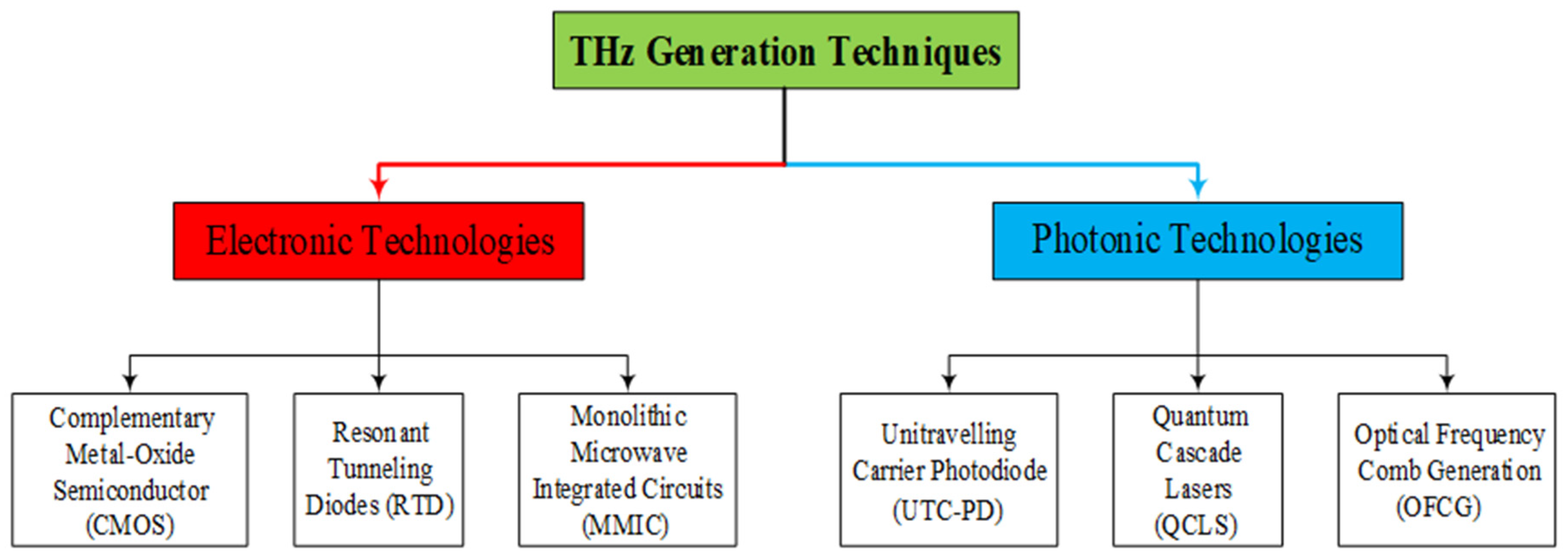
1. Introduction
1.1. Uni-Travelling Carrier Photodiode (UTC-PD)
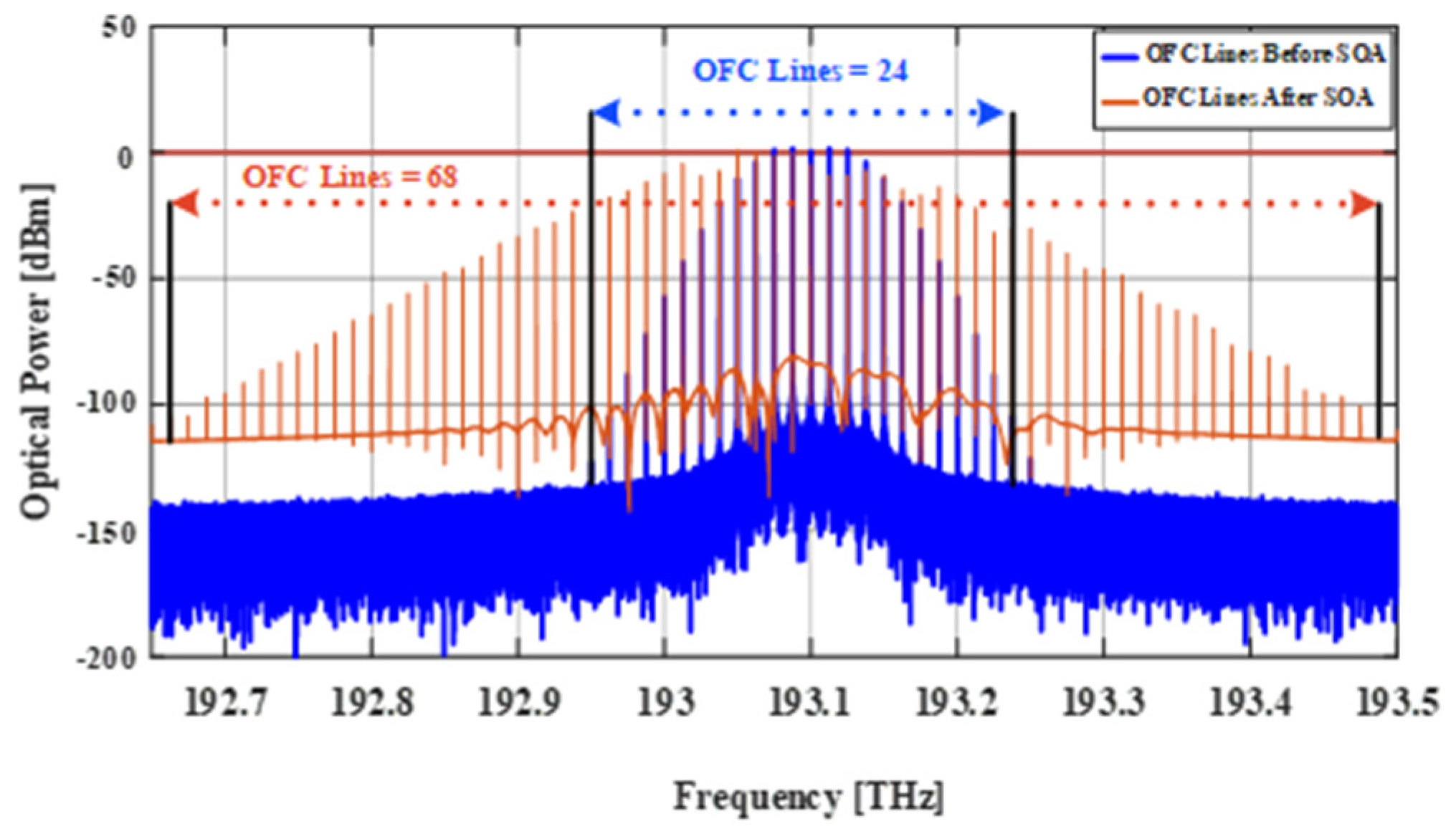
1.2. Optical Frequency Comb Generator (OFCG)
1.3. Paper’s Contributions
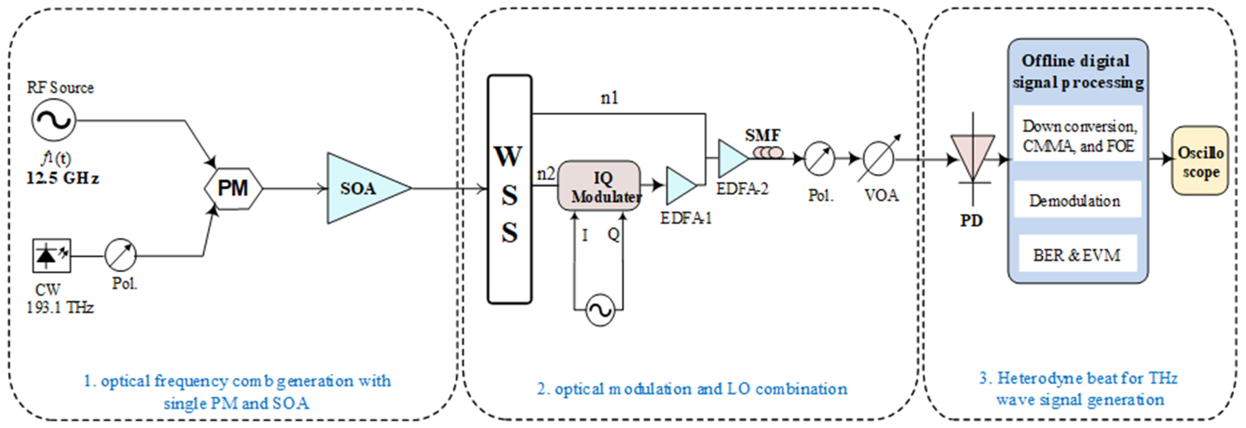
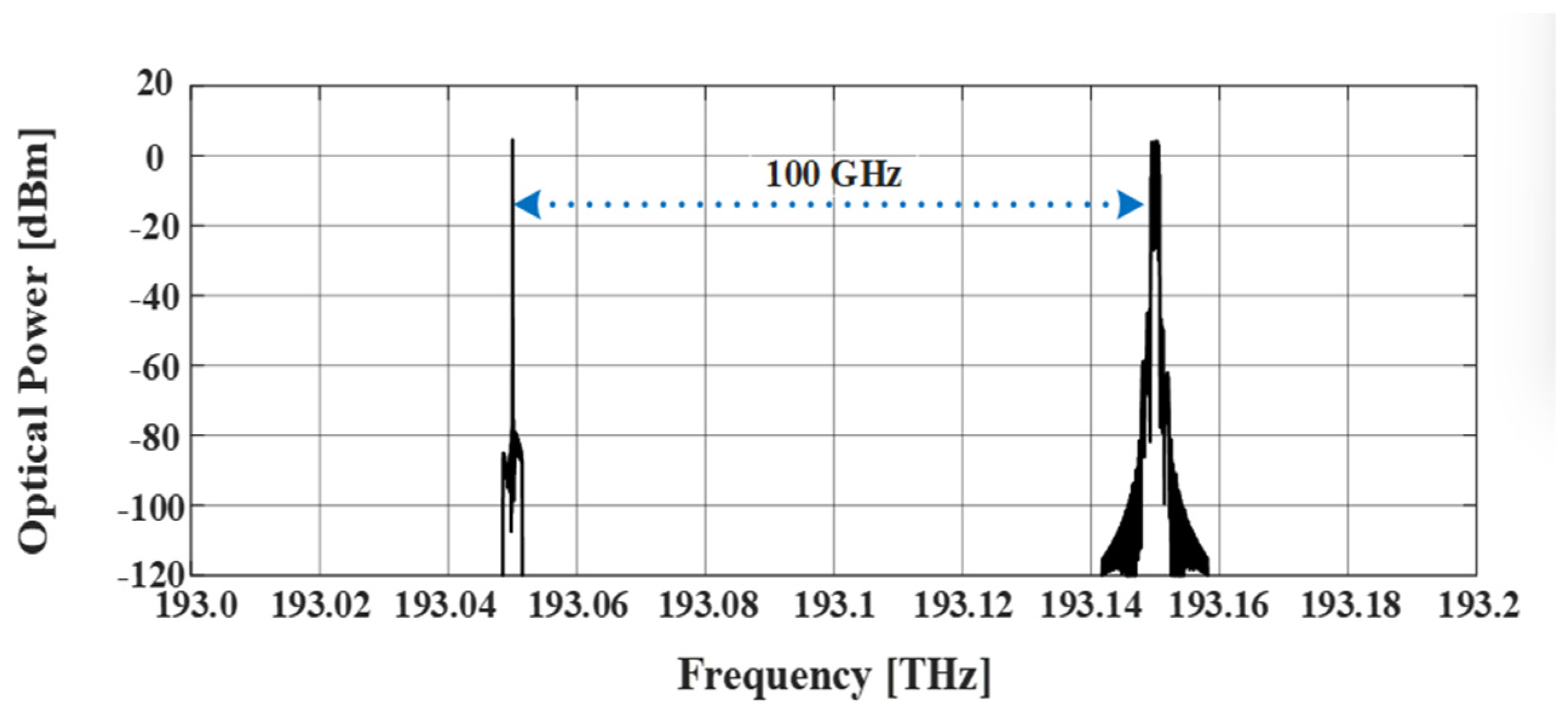
2. Simulation Model for THz Generation
3. Experimental Setup for THZ Signal Generation
4. Conclusions
Author Contributions
Funding
Data Availability Statement
Conflicts of Interest
References
- Bhat, J.R.; Alqahtani, S.A. 6G ecosystem: Current status and future perspective. IEEE Access 2021, 9, 43134–43167. [Google Scholar] [CrossRef]
- Ahad, A.; Jiangbina, Z.; Tahir, M.; Shayea, I.; Sheikh, M.A.; Rasheed, F. 6G and Intelligent Healthcare: Taxonomy, technologies, open issues and future research directions. Internet Things 2024, 25, 101068. [Google Scholar] [CrossRef]
- Singh, A.; Andrello, M.; Thawdar, N.; Jornet, J.M. Design and operation of a graphene-based plasmonic nano-antenna array for communication in the terahertz band. IEEE J. Sel. Areas Commun. 2020, 38, 2104–2117. [Google Scholar] [CrossRef]
- Ma, X.; Chen, Z.; Chen, W.; Li, Z.; Chi, Y.; Han, C.; Li, S. Joint channel estimation and data rate maximization for intelligent reflecting surface assisted terahertz MIMO communication systems. IEEE Access 2020, 8, 99565–99581. [Google Scholar] [CrossRef]
- Pennanen, H.; Hänninen, T.; Tervo, O.; Tölli, A.; Latva-Aho, M. 6G: The Intelligent Network of Everything. IEEE Access 2024, 13, 1319–1421. [Google Scholar] [CrossRef]
- Wei, H.; Ge, H.; Zhao, T.; Sharma, S.; Petru, M.; Dwivedi, S.P.; Kumar, A.; Abbas, M. Vanadium dioxide thin films-assisted terahertz meta-surface for simultaneous absorption, polarization conversion bi-functional switching, and wavefront operation. Results Phys. 2023, 53, 106970. [Google Scholar] [CrossRef]
- Alkhlefat, Y.; Esmail, M.A.; Ragheb, A.M.; Idrus, S.M.; Iqbal, F.M.; Alshebeili, S.A. Experimental Investigation of All-Optical Sub-THz Wavelength Conversion for 6G Communication Systems. IEEE Access 2024, 12, 133521–133531. [Google Scholar] [CrossRef]
- Yang, S.; Han, Q.; Sun, Z.; Wei, P.; Gao, C.; Zhang, Y.; Chen, Q.; Kang, J.; Wang, S.; Xiao, H.; et al. Stretchable, Transparent, and Ultra-Broadband Terahertz Shielding Thin Films Based on Wrinkled MXene Architectures. Nano-Micro Lett. 2024, 16, 165. [Google Scholar] [CrossRef]
- Xu, R.; Gao, S.; Izquierdo, B.S.; Gu, C.; Reynaert, P.; Standaert, A.; Gibbons, G.J.; Bosch, W. A review of broadband low-cost and high-gain low-terahertz antennas for wireless communications applications. IEEE Access 2020, 8, 57615–57629. [Google Scholar] [CrossRef]
- Sarieddeen, H.; Alouini, M.-S.; Al-Naffouri, T.Y. An overview of signal processing techniques for terahertz communications. Proc. IEEE 2021, 109, 1628–1665. [Google Scholar] [CrossRef]
- Nagatsuma, T.; Ducournau, G.; Renaud, C.C. Advances in terahertz communications accelerated by photonics. Nat. Photonics 2016, 10, 371–379. [Google Scholar] [CrossRef]
- Sengupta, K.; Nagatsuma, T.; Mittleman, D.M. Terahertz integrated electronic and hybrid electronic–photonic systems. Nat. Electron. 2018, 1, 622–635. [Google Scholar] [CrossRef]
- Kenneth, O.; Choi, W.; Zhong, Q.; Sharma, N.; Zhang, Y.; Han, R.; Ahmad, Z.; Kim, D.Y.; Kshattry, S.; Medvedev, I.R.; et al. Opening terahertz for everyday applications. IEEE Commun. Mag. 2019, 57, 70–76. [Google Scholar]
- Sengupta, K. Universal Terahertz Integrated Systems: Bridging the ‘THz’ and ‘Application’ Gap in the Next Decade. In Proceedings of the 2019 IEEE MTT-S International Microwave and RF Conference (IMARC), Mumbai, India, 13–15 December 2019; pp. 1–3. [Google Scholar]
- Hussain, M.; Awan, W.A.; Alzaidi, M.S.; Hussain, N.; Ali, E.M.; Falcone, F. Metamaterials and their application in the performance enhancement of reconfigurable antennas: A review. Micromachines 2023, 14, 349. [Google Scholar] [CrossRef]
- Hussain, M.; Zahra, H.; Abbas, S.M.; Zhu, Y. Flexible dielectric materials: Potential and applications in antennas and RF sensors. Adv. Electron. Mater. 2024, 10, 2400240. [Google Scholar] [CrossRef]
- Wu, D.; Ma, Y.; Sun, Y.; Huang, R.; Zhang, J.; Liu, S.; Zhuo, N.; Zhai, S.; Cheng, F.; Liu, F.; et al. Monolithic dispersion engineered mid-infrared quantum cascade laser frequency comb. Photonics Res. 2024, 12, 2566–2572. [Google Scholar] [CrossRef]
- Makhlouf, S.; Cojocari, O.; Hofmann, M.; Nagatsuma, T.; Preu, S.; Weimann, N.; Hübers, H.-W.; Stöhr, A. Terahertz sources and receivers: From the past to the future. IEEE J. Microw. 2023, 3, 894–912. [Google Scholar] [CrossRef]
- Huang, S.-W.; Yang, J.; Yang, S.-H.; Yu, M.; Kwong, D.-L.; Zelevinsky, T.; Jarrahi, M.; Wong, C.W. Globally stable microresonator Turing pattern formation for coherent high-power THz radiation on-chip. Phys. Rev. X 2017, 7, 041002. [Google Scholar] [CrossRef]
- Zhai, K.; Zhang, X.; Wang, W.; Chen, B.; Jin, Y.; Du, X.; Liu, Y.; Cui, J.; Li, Q.; Zhou, H.; et al. Photonic-Assisted Microwave Harmonic Down-Conversion Based on Four-Wave Mixing in a Silicon Integrated Waveguide Doped with Reverse-Biased P-i-N Junction. J. Light. Technol. 2023, 41, 7268–7275. [Google Scholar] [CrossRef]
- Wang, W.; Tan, Y.J.; Tan, T.C.; Kumar, A.; Pitchappa, P.; Szriftgiser, P.; Ducournau, G.; Singh, R. On-chip topological beamformer for multi-link terahertz 6G to XG wireless. Nature 2024, 632, 522–527. [Google Scholar] [CrossRef]
- Laube, S.M.; Gasser, C.; Schneider-Hornstein, K.; Zimmermann, H. Highly-Sensitive Integrating Optical Receiver with Large PIN Photodiode. IEEE Photonics J. 2024, 16, 7101809. [Google Scholar] [CrossRef]
- Tian, Y.; Li, Y.; Dong, B.; Xiong, B.; Zhang, J.; Sun, C.; Hao, Z.; Wang, J.; Wang, L.; Han, Y.; et al. High-power MUTC Photodiode Module for Photonics-assisted Beyond 100 Gb/s Wireless Sub-THz Communications in the F-band. J. Light. Technol. 2024, 42, 5616–5623. [Google Scholar] [CrossRef]
- Che, M.; Kondo, K.; Kato, K. Generating and enhancing THz pulses via an antenna-coupled unitraveling-carrier photodiode array. IEEE Trans. Terahertz Sci. Technol. 2023, 13, 280–285. [Google Scholar] [CrossRef]
- Shi, J.-W. Ultra-Fast Photodiodes under Zero-and Forward-Bias Operations. In Sensors for Diagnostics and Monitoring; CRC Press: Boca Raton, FL, USA, 2018; pp. 65–96. [Google Scholar]
- Chen, Q.; Zhang, X.; Sharawi, M.S.; Kashyap, R.; High, A.I. High–Power Photodiodes: From Fundamentals to Applications. Appl. Sci. 2024, 14, 3410. [Google Scholar] [CrossRef]
- Ishibashi, T.; Shimizu, N.; Kodama, S.; Ito, H.; Nagatsuma, T.; Furuta, T. Uni-traveling-Carrier Photodiodes. In Ultrafast Electronics and Optoelectronics; Optica Publishing Group: Washington, DC, USA, 1997. [Google Scholar]
- Ito, H.; Nakajima, F.; Furuta, T.; Yoshino, K.; Hirota, Y.; Ishibashi, T. Photonic terahertz-wave generation using antenna-integrated uni-travelling-carrier photodiode. Electron. Lett. 2003, 39, 1828–1829. [Google Scholar] [CrossRef]
- Shehata, M.; Wang, Y.; He, J.; Kandeepan, S.; Wang, K. Optical and Terahertz Wireless Technologies: The Race to 6G Communications. IEEE Wirel. Commun. 2023, 30, 10–18. [Google Scholar] [CrossRef]
- Renaud, C.C.; Robertson, M.; Rogers, D.; Firth, R.; Cannard, P.J.; Moore, R.; Seeds, A.J.; Jäger, D.; Stöhr, A. A High Responsivity, Broadband Waveguide Uni-Travelling Carrier Photodiode. In Millimeter-Wave and Terahertz Photonics; SPIE: Bellingham, WA, USA, 2006; Volume 6194, pp. 87–94. [Google Scholar]
- Yu, X.; Jia, S.; Hu, H.; Galili, M.; Morioka, T.; Jepsen, P.U.; Oxenløwe, L.K. 160 Gbit/s photonics wireless transmission in the 300–500 GHz band. Apl. Photonics 2016, 1, 081301. [Google Scholar] [CrossRef]
- Ullah, R.; Bo, L.; Ullah, S.; Mao, Y.; Feng, T.; Xin, X. Cost effective OLT designed from optical frequency comb generator based EML for1. 22 Tbps wavelength division multiplexed passive optical network. Opt. Fiber Technol. 2018, 43, 49–56. [Google Scholar] [CrossRef]
- He, J.; Long, F.; Deng, R.; Shi, J.; Dai, M.; Chen, L. Flexible multiband OFDM ultra-wideband services based on optical frequency combs. J. Opt. Commun. Netw. 2017, 9, 393–400. [Google Scholar] [CrossRef]
- Singh, N.; Bansal, B.N. An ultra-dense spacing-based PON by incorporating dual drive Mach–Zehnder modulator for comb generation. J. Opt. Commun. 2024, 44, s359–s365. [Google Scholar] [CrossRef]
- Verma, P.; Singh, S. An approach to generate cross-polarization modulation-enabled optical frequency comb with enhanced spectral flatness in traveling-wave semiconductor optical amplifiers. J. Opt. 2024, 26, 105703. [Google Scholar] [CrossRef]
- Ullah, R.; Ullah, S.; Chen, S.; Almadhor, A.; Al-Atawi, A.A.; Jianxin, R.; Khan, M.; Pau, G. 1.12 Tbps-16QAM Uncompensated LongHaul Transmission Employing a new SelfOscillating Optical Frequency Comb Generator both at transmitter and receiver. IEEE Photonics J. 2024, 16, 7200507. [Google Scholar] [CrossRef]
- Yang, W.Y.; Jiang, Z.F.; Cui, B.; Jin, Y.H. Generation of Wideband Optical Frequency Comb with Coincident Polarization Based on Gain-Switched Vertical-Cavity Surface-Emitting Laser under Orthogonal Optical Injection. IEEE Access 2024, 12, 181454–181461. [Google Scholar] [CrossRef]
- Zhang, S.; Wang, Z.; Zuo, X.; Ma, C.; Jiang, Y.; Yu, J. Generation of a Flat Optical Frequency Comb via a Cascaded Dual-Parallel Mach–Zehnder Modulator and Phase Modulator without Using the Fundamental Tone. Photonics 2023, 10, 1340. [Google Scholar] [CrossRef]
- Sohanpal, R.S. Optical Frequency Comb Generation and Applications in Coherent Optical Communications. Master’s Thesis, University College London, London, UK, 2024. [Google Scholar]
- Verma, P.; Singh, S. Exploiting cross-polarization modulation in semiconductor optical amplifier-Mach-Zehnder interferometer for enhanced optical frequency comb generation. Opt. Eng. 2024, 63, 115101. [Google Scholar] [CrossRef]
- Ullah, S.; Ullah, R.; Zhang, Q.; Khalid, H.A.; Memon, K.A.; Khan, A.; Tian, F.; Xiangjun, X. Ultra-wide and flattened optical frequency comb generation based on cascaded phase modulator and LiNbO3-MZM offering terahertz bandwidth. IEEE Access 2020, 8, 76692–76699. [Google Scholar] [CrossRef]
- Shen, J.; Wu, S.; Li, D. Ultra-flat optical frequency comb generation based on phase modulation with simple digital driving signal. Optik 2019, 198, 163254. [Google Scholar] [CrossRef]
- Liu, Y.; Wu, S. Proposed Scheme for Ultra-Flat Optical Frequency Comb Generation Based on Dual-Drive Mach–Zehnder Modulators and Bidirectional Recirculating Frequency Shifting in Single Loop. Photonics 2022, 9, 514. [Google Scholar] [CrossRef]
- Cui, Y.; Wang, Z.; Zuo, X.; Xu, Y.; Jiang, Y.; Yu, J.; Huang, Z. Flat optical frequency comb generation by using one DPMZM and superposed harmonics. Opt. Commun. 2023, 531, 129223. [Google Scholar] [CrossRef]
- Qiu, J.; Jin, X.; Yang, L.; Xu, Y.; Wei, B. Generation of a 25-line flattened optical frequency comb and its coherent beating properties. Appl. Opt. 2022, 61, 3871–3876. [Google Scholar] [CrossRef]
- Cui, Y.; Wang, Z.; Xu, Y.; Jiang, Y.; Yu, J.; Huang, Z. Generation of flat optical frequency comb using cascaded PMs with combined harmonics. IEEE Photonics Technol. Lett. 2022, 34, 490–493. [Google Scholar] [CrossRef]
- Sharma, V.; Singh, S. Development of frequency comb generation by spectral broadening of periodic optical pulses in semiconductor laser amplifiers. J. Opt. 2022, 24, 045701. [Google Scholar] [CrossRef]
- Li, J.; Ma, H.; Li, Z.; Zhang, X. Optical frequency comb generation based on dual-polarization IQ modulator shared by two polarization-orthogonal recirculating frequency shifting loops. IEEE Photonics J. 2017, 9, 1–10. [Google Scholar] [CrossRef]
- Ujjwal; Kumar, R. Optical Frequency Comb Generator Employing Two Cascaded Frequency Modulators and Mach–Zehnder Modulator. Electronics 2023, 12, 2762. [Google Scholar] [CrossRef]
- Gao, T.; Zhang, Y.; Li, J.; Li, S.; Zhang, Z.; Zhang, S.; Liu, Y. Tunable microwave frequency comb generation via periodic relaxation oscillation in directly modulated laser. Opt. Laser Technol. 2024, 170, 110295. [Google Scholar] [CrossRef]
- Wang, X.; Li, Z.; Lyu, W.; Lyu, Y.; Zeng, C.; Zhang, Z.; Zhang, S.; Zhang, Y.; Li, H.; Xia, J.; et al. Flat optical frequency comb generation based on monolithic integrated LNOI intensity and phase modulator. Photonics 2022, 9, 495. [Google Scholar] [CrossRef]
- Fang, X.; Lai, Z.; Guo, P.; Geng, J.; Zhang, Z. Large-Bandwidth Optical Frequency Comb Generator Based on Dual-Parallel Mach-Zehnder and Cascaded Intensity Modulators. SSRN 2023, SSRN:4395465. [Google Scholar]
- Xu, M.; He, M.; Zhu, Y.; Yu, S.; Cai, X. Flat optical frequency comb generator based on integrated lithium niobate modulators. J. Light. Technol. 2022, 40, 339–345. [Google Scholar] [CrossRef]
- Lv, X.; Liu, J.; Wu, S. Flat optical frequency comb generation based on polarization modulator with RF frequency multiplication circuit and dual-parallel Mach-Zehnder modulator. Optik 2019, 183, 706–712. [Google Scholar] [CrossRef]
- Sharma, V.; Singh, S.; Lovkesh. Cross-phase modulation based ultra-flat 90-line optical frequency comb generation. Opt. Quantum Electron. 2021, 53, 1–12. [Google Scholar] [CrossRef]
- Zhang, X.; Zhao, L.; Zhang, J.; Zhang, J.; Zhang, Z.; Shen, M.; Chen, S.; Zheng, X.; Jiang, T. LSTM-Resnet-assisted Linearization for the Dual Frequency Comb Photonic RF Channelized Receiver. J. Light. Technol. 2024, 42, 7725–7735. [Google Scholar] [CrossRef]
- Hasanuzzaman, G.; Shams, H.; Renaud, C.C.; Mitchell, J.; Seeds, A.J.; Iezekiel, S. Tunable THz signal generation and radio-over-fiber link based on an optoelectronic oscillator-driven optical frequency comb. J. Light. Technol. 2019, 38, 5240–5247. [Google Scholar] [CrossRef]
- Yu, J.; Li, K.; Chen, Y.; Zhao, L.; Huang, Y.; Li, Y.; Ma, J.; Shan, F. Terahertz-wave generation based on optical frequency comb and single Mach-Zehnder modulator. IEEE Photonics J. 2020, 12, 1–8. [Google Scholar] [CrossRef]
- Ding, Y.-Y.; Gao, F.; Yuan, H.-H.; Lv, Z.-R.; Yang, T. 1–2.9-Thz tunable terahertz beat signal generation based on inas/inp quantum-dot mode-locked laser. IEEE Photonics Technol. Lett. 2018, 30, 1234–1237. [Google Scholar] [CrossRef]
- Wang, H.; Lu, D.; Zhang, R.; Zhao, L. Photonic Terahertz Carrier Generation Using an Optical Feedback Mode-Lock Laser Diode. IEEE Photonics J. 2021, 13, 1–6. [Google Scholar] [CrossRef]
- Jia, S.; Lo, M.-C.; Zhang, L.; Ozolins, O.; Udalcovs, A.; Kong, D.; Pang, X.; Yu, X.; Xiao, S.; Popov, S.; et al. Integrated Dual-DFB Laser for 408 GHz Carrier Generation Enabling 131 Gbit/s Wireless Transmission over 10.7 Meters. In Proceedings of the Optical Fiber Communication Conference, Washington, DC, USA, 3–7 March 2019. Paper Th1C.2. [Google Scholar]
- Alkhlefat, Y.; Ragheb, A.M.; Esmail, M.A.; Alshebeili, S.A.; Seleem, H.E. Millimeter wave switching for single carrier and aggregated filter bank multi-carrier signals in radio over fiber networks. Opt. Fiber Technol. 2020, 60, 102335. [Google Scholar] [CrossRef]
- Shi, B.; Calabretta, N.; Stabile, R. InP photonic integrated multi-layer neural networks: Architecture and performance analysis. APL Photonics 2022, 7, 010801. [Google Scholar] [CrossRef]
- Bougaud, A.; Llopis, O.; Fernandez, A. A parametric study of a SOA based COEO for phase noise performance and reliable operation. J. Light. Technol. 2023, 42, 2245–2251. [Google Scholar] [CrossRef]
- Ragheb, A.M.; Tareq, Q.; Esmail, M.A.; Alrabeiah, M.R.; Alshebeili, S.A.; Khan, M.Z. Enabling WiGig communications using quantum-dash laser source under smoky weather conditions. IEEE Photonics J. 2022, 14, 1–7. [Google Scholar] [CrossRef]
- Shafik, R.A.; Rahman, M.S.; Islam, A.R. On the Extended Relationships among EVM, BER and SNR as Performance Metrics. In Proceedings of the 2006 International Conference on Electrical and Computer Engineering (ICECE), Dhaka, Bangladesh, 19–21 December 2006; pp. 408–411. [Google Scholar]


| Generation Technique | Modulation Format | Freq Separation in RF Source (GHz) | Generated Frequency (THz) | Method of Conduct | Remarks | Reference |
|---|---|---|---|---|---|---|
| Tunable optoelectronic oscillator (OEO) | QPSK/16 QAM | 17.33 | 0.101 and 0.242 | Experimental | The generated THz signals depend on the OEO stability, which makes the implementation critical. | [57] |
| Optical frequency comb using two-phase modulators | QPSK/16 QAM | 25 | 0.4 | Simulation | This paper utilized two cascaded phase modulators, leading to expensive implementation. | [58] |
| Single-section chirped multiple InAs/InP quantum-dot (QD) mode-locked laser (MLL) | -- | -- | 1–2.9 | Experimental | The programmable optical filter can work only in the C-band, so the longer wavelength modes cannot be extracted. | [59] |
| Optical feedback mode-lock laser diode | 64-QAM | -- | 0.042–0.377 | Experimental | Focusing on reducing the optical linewidth to use higher-order modulation. | [60] |
| Integrated dual-distributed feedback (DFB) laser | 16QAM-OFDM | 9.951 | 0.408 | Experimental | This paper used a monolithically integrated (DFB) laser chip attached to a (UTC-PD) with a THz antenna | [61] |
| OFCG using phase modulator with SOA and UTC-PD | QPSK | 12.5 | 0.1 | Simulation/experimental | This work presents a simple and efficient method for generating THz signals. | This work |
| Modulation Parameters | Value |
|---|---|
| Modulation order | QPSK |
| RF carrier frequency | 12.5 GHz |
| RF amplitude | 1 a.u |
| Signal data rate | 4 Gbps |
| CW laser 1 frequency | 193.1 THz |
| CW laser 1 power | 1 mW |
| CW laser 1 linewidth | 100 kHz |
| SRRC roll-off factor | 0.18 |
| Responsivity of PD | 1 A/W |
| Thermal noise | 10 × A/Hz(1/2) |
| SOA’s Parameters | |
| Injection current (IC) | 0.25 A |
| Height Length | 80 μm 500 μm |
| Width | 3 μm |
| Optical confinement factor | 0.99 |
| Index to gain coupler | 3.8 |
| Waveguide loss coefficient | 4000 1/m |
| DD-MZM’s Parameters | |
| Extinction ratio | 35 dB |
| 0.5 V 0.5 V | |
| Insertion loss | 6 dB |
| Operation temperature | 25 degC |
| Extinction ratio | 35 dB |
| Component | Model Number |
|---|---|
| Continuous wave (CW) | Koheras ADJUSTIK |
| Vector signal generator (VSG) | KEYSIGHT E8267D |
| Kamelian SOA | SOA-NL-L1-C-FA |
| Amonics SOA | SOA15-20-R |
| Amonics EDFA | EDFA-PA-40-B-FA |
| WSS | FINISAR WaveShaper 4000s 4903306 |
| IQ modulator | FUJITSU 78110 |
| Photodiode (PD) | FINISAR XPDV4121R 10 125 011 235130 B9W.0375 |
| Analyzer | Infiniium DSO-X-93204A |
| Low-noise amplifier | QuinStar QLW-24403336-J0 |
| Horn antennas | SAGE SAR-2507-28-S2 |
| Digital storage oscilloscope | Keysight DSOX 932048 |
| Vector signal analyzer software | Keysight VSA 89600 |
Disclaimer/Publisher’s Note: The statements, opinions and data contained in all publications are solely those of the individual author(s) and contributor(s) and not of MDPI and/or the editor(s). MDPI and/or the editor(s) disclaim responsibility for any injury to people or property resulting from any ideas, methods, instructions or products referred to in the content. |
© 2025 by the authors. Licensee MDPI, Basel, Switzerland. This article is an open access article distributed under the terms and conditions of the Creative Commons Attribution (CC BY) license (https://creativecommons.org/licenses/by/4.0/).
Share and Cite
Alkhlefat, Y.; Ragheb, A.M.; Esmail, M.A.; Idrus, S.M.; Iqbal, F.M.; Alshebeili, S.A. Experimental Demonstration of Terahertz-Wave Signal Generation for 6G Communication Systems. Optics 2025, 6, 34. https://doi.org/10.3390/opt6030034
Alkhlefat Y, Ragheb AM, Esmail MA, Idrus SM, Iqbal FM, Alshebeili SA. Experimental Demonstration of Terahertz-Wave Signal Generation for 6G Communication Systems. Optics. 2025; 6(3):34. https://doi.org/10.3390/opt6030034
Chicago/Turabian StyleAlkhlefat, Yazan, Amr M. Ragheb, Maged A. Esmail, Sevia M. Idrus, Farabi M. Iqbal, and Saleh A. Alshebeili. 2025. "Experimental Demonstration of Terahertz-Wave Signal Generation for 6G Communication Systems" Optics 6, no. 3: 34. https://doi.org/10.3390/opt6030034
APA StyleAlkhlefat, Y., Ragheb, A. M., Esmail, M. A., Idrus, S. M., Iqbal, F. M., & Alshebeili, S. A. (2025). Experimental Demonstration of Terahertz-Wave Signal Generation for 6G Communication Systems. Optics, 6(3), 34. https://doi.org/10.3390/opt6030034