Dispersion Management in 10-PW Laser Front End


Abstract
1. Introduction
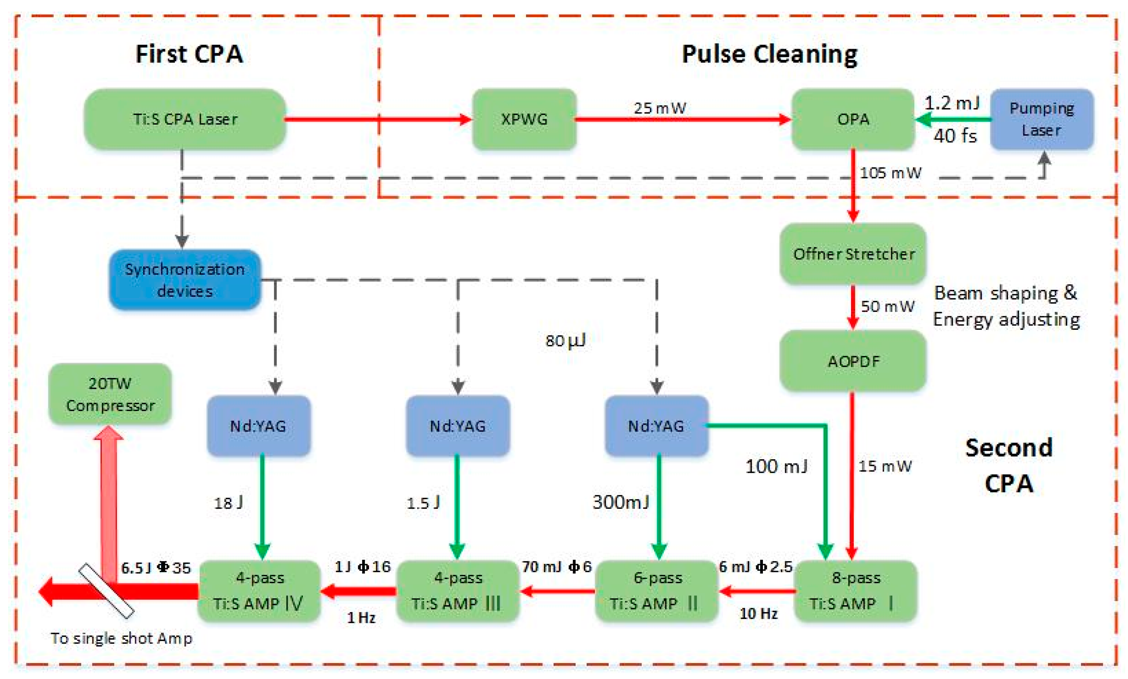
2. Chirped Pulse Amplification Front End
3. Results and Conclusions
Author Contributions
Funding
Conflicts of Interest
References
- Strickland, D.; Mourou, G. Compression of amplified chirped optical pulses. Opt. Commun. 1985, 56, 219–221. [Google Scholar] [CrossRef]
- Dubietis, A.; Jonusauskas, G.; Piskarskas, A. Powerful femtosecond pulse generation by chirped and stretched pulse parametric amplification in BBO crystal. Opt. Commun. 1992, 88, 437–440. [Google Scholar] [CrossRef]
- Stepanenko, Y.; Radzewicz, C. High-gain multipass noncollinear optical parametric chirped pulse amplifier. Appl. Phys. Lett. 2005, 86, 211120. [Google Scholar] [CrossRef]
- Stepanenko, Y.; Radzewicz, C. Multipass non-collinear optical parametric amplifier for femtosecond pulses. Opt. Express 2006, 14, 779–785. [Google Scholar] [CrossRef] [PubMed]
- Li, X.L.; Liu, H.J.; Wang, H.Y.; Zhao, W.; Wang, Y.; Shi, S.X. Compact high gain double-pass optical parametric chirped pulse amplifier. Eur. Phys. J. D 2008, 47, 309–312. [Google Scholar] [CrossRef]
- Danson, C.N.; Haefner, C.; Bromage, J.; Butcher, T.; Chanteloup, J.-C.F.; Chowdhury, E.A.; Galvanauskas, A.; Gizzi, L.A.; Hein, J.; Hillier, D.I.; et al. Petawatt and exawatt class lasers worldwide. High Power Laser Sci. Eng. 2019, 7. [Google Scholar] [CrossRef]
- Chériaux, G.; Giambruno, F.; Fréneaux, A.; Leconte, F.; Ramirez, L.P.; Georges, P.; Druon, F.; Papadopoulos, D.N.; Pellegrina, A.; Le Blanc, C.; et al. Apollon-10P: Status and implementation. In Proceedings of the AIP Conference, Szeged, Hungary, 14–18 November 2011; AIP Publishing: Melville, NY, USA, 2012; Volume 1462, pp. 78–83. [Google Scholar]
- Hernandez-Gomez, C.; Blake, S.P.; Chekhlov, O.; Clarke, R.; Dunne, A.M.; Galimberti, M.; Hancock, S.; Heathcote, R.; Holligan, P.; Lyachev, A.; et al. The vulcan 10 PW project. J. Physics: Conf. Ser. 2010, 244, 032006. [Google Scholar] [CrossRef]
- Li, W.; Gan, Z.; Yu, L.; Wang, C.; Liu, Y.; Guo, Z.; Xu, L.; Xu, M.; Hang, Y.; Xu, Y.; et al. 339 J high-energy Ti:sapphire chirped-pulse amplifier for 10 PW laser facility. Opt. Lett. 2018, 43, 5681–5684. [Google Scholar] [CrossRef] [PubMed]
- Kane, S.; Squier, J. Fourth-order-dispersion limitations of aberration-free chirped-pulse amplification systems. J. Opt. Soc. Am. B 1997, 14, 1237. [Google Scholar] [CrossRef]
- Verluise, F.; Laude, V.; Cheng, Z.; Spielmann, C.; Tournois, P. Amplitude and phase control of ultrashort pulses by use of an acousto-optic programmable dispersive filter: Pulse compression and shaping. Opt. Lett. 2000, 25, 575–577. [Google Scholar] [CrossRef]
- Gibson, E.A.; Gaudiosi, D.M.; Kapteyn, H.; Jimenez, R.; Kane, S.; Huff, R.; Durfee, C.; Squier, J. Efficient reflection grisms for pulse compression and dispersion compensation of femtosecond pulses. Opt. Lett. 2006, 31, 3363–3365. [Google Scholar] [CrossRef]
- Zeek, E.; Maginnis, K.; Backus, S.; Russek, U.; Murnane, M.; Mourou, G.; Kapteyn, H.; Vdovin, G. Pulse compression by use of deformable mirrors. Opt. Lett. 1999, 24, 493–495. [Google Scholar] [CrossRef] [PubMed]
- Li, S.; Wang, C.; Liu, Y.; Xu, Y.; Liu, Z.; Lu, J.; Li, Y.; Liu, X.; Li, Z.; Leng, Y.; et al. Dispersion management of the SULF front end. Quantum Electron. 2017, 47, 179–183. [Google Scholar] [CrossRef]
- Li, S.; Wang, C.; Liu, Y.; Xu, Y.; Li, Y.; Liu, X.; Gan, Z.; Yu, L.; Liang, X.Y.; Leng, Y.; et al. High-order dispersion control of 10-petawatt Ti:sapphire laser facility. Opt. Express 2017, 25, 17488–17498. [Google Scholar] [CrossRef] [PubMed]
- Gan, Z.; Yu, L.; Li, S.; Wang, C.; Liang, X.; Liu, Y.; Li, W.; Guo, Z.; Fan, Z.; Yuan, X.; et al. 200 J high efficiency Ti:sapphire chirped pulse amplifier pumped by temporal dual-pulse. Opt. Express 2017, 25, 5169–5178. [Google Scholar] [CrossRef] [PubMed]
- Li, Z.; Wang, C.; Li, S.; Xu, Y.; Chen, L.; Dai, Y.; Leng, Y. Fourth-order dispersion compensation for ultra-high-power femtosecond lasers. Opt. Commun. 2015, 357, 71–77. [Google Scholar] [CrossRef]
- Oliver, J.B.; Bromage, J.; Smith, C.; Sadowski, D.; Dorrer, C.; Rigatti, A.L. Plasma-ion-assisted coatings for 15 femtosecond laser systems. Appl. Opt. 2014, 53, A221–A228. [Google Scholar] [CrossRef]
- Sun, Z.; Chai, L.; Zhang, Z.; Wang, C.; Zhang, W.; Xie, X.; Huang, X.; Yuan, X. Mutual compensation of higher-order dispersion in chirped pulse amplification system with regenerative amplifier. Opt. Laser Technol. 2007, 39, 29–33. [Google Scholar] [CrossRef]
- Yakovlev, I. Stretchers and compressors for ultra-high power laser systems. Quantum Electron. 2014, 44, 393–414. [Google Scholar] [CrossRef]
- Dorrer, C. Spatiotemporal metrology of broadband optical pulses. IEEE J. Sel. Top. Quantum Electron. 2019, 25, 1–16. [Google Scholar] [CrossRef]
- Fiorini, C.; Sauteret, C.; Rouyer, C.; Blanchot, N.; Seznec, S.; Migus, A. Temporal aberrations due to misalignments of a stretcher-compressor system and compensation. IEEE J. Quantum Electron. 1994, 30, 1662–1670. [Google Scholar] [CrossRef]
- Osvay, K.; Ross, I.N. On a pulse compressor with gratings having arbitrary orientation. Opt. Commun. 1994, 105, 271–278. [Google Scholar] [CrossRef]
- Pretzler, G.; Kasper, A.; Witte, K. Angular chirp and tilted light pulses in CPA lasers. Appl. Phys. A 2000, 70, 1–9. [Google Scholar] [CrossRef]
- Osvay, K.; Kovacs, A.P.; Heiner, Z.; Kurdi, G.; Klebniczki, J.; Csatari, M. Angular dispersion and temporal change of femtosecond pulses from misaligned pulse compressors. IEEE J. Sel. Top. Quantum Electron. 2004, 10, 213–220. [Google Scholar] [CrossRef]
- Bromage, J.; Dorrer, C.; Millecchia, M.; Bunkenburg, J.; Jungquist, R.; Zuegel, J.D. A front end for ultra-intense OPCPA. AIP Conf. Proc. 2012, 1462, 74–77. [Google Scholar]
- Bahk, S.-W.; Rousseau, P.; Planchon, T.A.; Chvykov, V.; Kalintchenko, G.; Maksimchuk, A.; Mourou, G.A.; Yanovsky, V. Generation and characterization of the highest laser intensities (10(22) W/cm2). Opt. Lett. 2004, 29, 2837–2839. [Google Scholar] [CrossRef]
- Yoon, J.W.; Jeon, C.; Shin, J.; Lee, S.K.; Lee, H.W.; Choi, I.W.; Kim, H.T.; Sung, J.H.; Nam, C.H. Achieving the laser intensity of 5.5x10(22) W/cm(2) with a wavefront-corrected multi-PW laser. Opt. Express. 2019, 27, 20412–20420. [Google Scholar] [CrossRef]
- Tiwari, G.; Gaul, E.; Martinez, M.; Dyer, G.; Gordon, J.; Spinks, M.; Toncian, T.; Bowers, B.; Jiao, X.; Kupfer, R.; et al. Beam distortion effects upon focusing an ultrashort petawatt laser pulse to greater than 1022 W/cm2. Opt. Lett. 2019, 44, 2764–2767. [Google Scholar] [CrossRef]
- Guo, Z.; Yu, L.; Wang, J.; Wang, C.; Liu, Y.; Gan, Z.; Li, W.; Leng, Y.; Liang, X.; Li, R. Improvement of the focusing ability by double deformable mirrors for 10-PW-level Ti: Sapphire chirped pulse amplification laser system. Opt. Express 2018, 26, 26776–26786. [Google Scholar] [CrossRef]
- Turcu, I.C.E.; Shen, B.; Neely, D.; Sarri, G.; Tanaka, K.A.; McKenna, P.; Mangles, S.P.D.; Yu, T.-P.; Luo, W.; Zhu, X.-L.; et al. Quantum electrodynamics experiments with colliding petawatt laser pulses. High Power Laser Sci. Eng. 2019, 7. [Google Scholar] [CrossRef]
- Liu, F.; Wang, Z.H.; Ma, J.L.; Zhang, L.; Wang, J.; Wang, S.; Lin, X.X.; Li, Y.T.; Chen, L.M.; Wei, Z.Y.; et al. Compression grating alignment by far-field monitoring. Appl. Phys. A 2010, 101, 587–591. [Google Scholar] [CrossRef]
- Li, S.; Li, Z.; Wang, C.; Xu, Y.; Li, Y.; Leng, Y.; Li, R. Broadband spectrographic method for precision alignment of compression gratings. Opt. Eng. 2016, 55, 086105. [Google Scholar] [CrossRef]
- Börzsönyi, A.; Mangin-Thro, L.; Cheriaux, G.; Osvay, K. Two-dimensional single-shot measurement of angular dispersion for compressor alignment. Opt. Lett. 2013, 38, 410–412. [Google Scholar] [CrossRef] [PubMed]
- Available online: http://www.unitedcrystals.com/KDPProp.html. (accessed on 15 July 2018).
- Ghosh, G. Sellmeier coefficients and dispersion of thermo-optic coefficients for some optical glasses. Appl. Opt. 1997, 36, 1540–1546. [Google Scholar] [CrossRef] [PubMed]
- Chériaux, G.; Walker, B.; DiMauro, L.F.; Rousseau, P.; Salin, F.; Chambaret, J.P. Aberration-free stretcher design for ultrashort-pulse amplification. Opt. Lett. 1996, 21, 414–416. [Google Scholar] [CrossRef] [PubMed]
- Pirozhkov, A.S.; Fukuda, Y.; Nishiuchi, M.; Kiriyama, H.; Sagisaka, A.; Ogura, K.; Mori, M.; Kishimoto, M.; Sakaki, H.; Dover, N.P.; et al. Approaching the diffraction-limited, bandwidth-limited Petawatt. Opt. Express 2017, 25, 20486. [Google Scholar] [CrossRef] [PubMed]


| Crystal Thickness | Number of Passes | Optical Path Length | |
|---|---|---|---|
| Amp I | 15 mm | 8 | 120 mm |
| Amp II | 15 mm | 6 | 90 mm |
| Amp III | 25 mm | 4 | 100 mm |
| Amp III | 35 mm | 4 | 140 mm |
| Total | 450 mm | ||
| Incident angle | Grating oblique distance | Grating grooves | |
| Stretcher | 50.75 deg | 2960 mm | 1480 mm−1 |
| Compressor | 50.9737 deg | 2974 mm | 1480 mm−1 |
| GVD/fs2 | TOD/fs3 | FOD/fs4 | |
| Stretcher | 7.0632 × 10⁶ | −1.4243 × 10⁷ | 4.6033 × 10⁷ |
| Material | 2.6151 × 10⁴ | 1.8977 × 10⁴ | −7.0008 × 10³ |
| Compressor | −7.0794 × 10⁶ | 1.4232 × 10⁷ | −4.5863 × 10⁷ |
| Residual (AOPDF) | −1 × 10⁴ | −7.309 × 10³ | 1.6263 × 10⁵ |
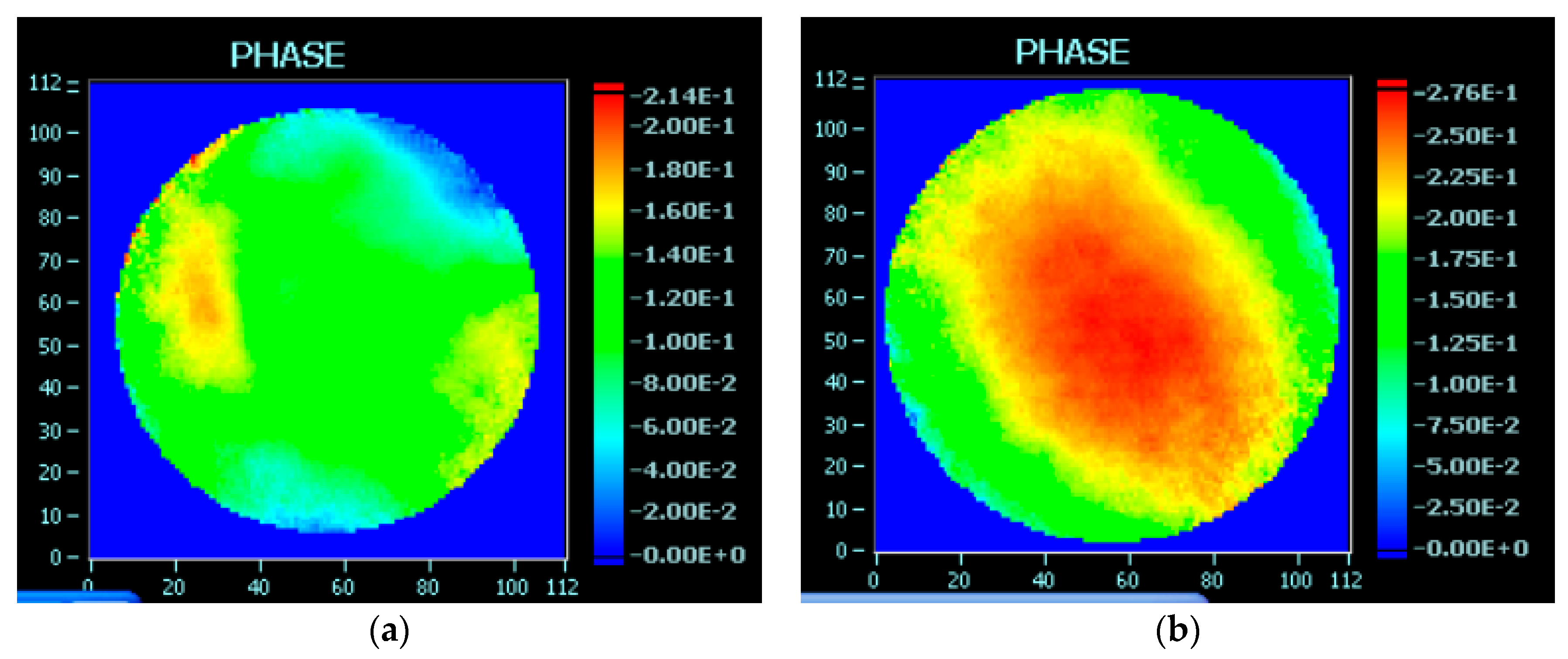
| PtV(λ) | RMS(λ) | Strehl Ratio | |
|---|---|---|---|
| Before stretcher | 0.214 | 0.033 | 0.97 |
| After stretcher | 0.276 | 0.044 | 0.99 |
© 2020 by the authors. Licensee MDPI, Basel, Switzerland. This article is an open access article distributed under the terms and conditions of the Creative Commons Attribution (CC BY) license (http://creativecommons.org/licenses/by/4.0/).
Share and Cite
Liu, X.; Wang, C.; Wang, X.; Lu, X.; Bai, P.; Liu, Y.; Li, Y.; Liu, K.; Yu, L.; Leng, Y.; et al. Dispersion Management in 10-PW Laser Front End. Optics 2020, 1, 191-201. https://doi.org/10.3390/opt1020015
Liu X, Wang C, Wang X, Lu X, Bai P, Liu Y, Li Y, Liu K, Yu L, Leng Y, et al. Dispersion Management in 10-PW Laser Front End. Optics. 2020; 1(2):191-201. https://doi.org/10.3390/opt1020015
Chicago/Turabian StyleLiu, Xingyan, Cheng Wang, Xinliang Wang, Xiaoming Lu, Peile Bai, Yanqi Liu, Yanyan Li, Keyang Liu, Lianghong Yu, Yuxin Leng, and et al. 2020. "Dispersion Management in 10-PW Laser Front End" Optics 1, no. 2: 191-201. https://doi.org/10.3390/opt1020015
APA StyleLiu, X., Wang, C., Wang, X., Lu, X., Bai, P., Liu, Y., Li, Y., Liu, K., Yu, L., Leng, Y., & Li, R. (2020). Dispersion Management in 10-PW Laser Front End. Optics, 1(2), 191-201. https://doi.org/10.3390/opt1020015