Article

Analysis on the Leakage and Rubbing Force of the Combined Finger Seal Based on Equivalent Dynamic Model Considering Thermal Effects

1
School of Mechanical Engineering, Northwestern Polytechnical University, Xi’an 710072, China
2
AEEC Hunan Aviation Powerplant Research Institute, Zhuzhou 412002, China
*
Author to whom correspondence should be addressed.
Appl. Mech. 2025, 6(4), 80; https://doi.org/10.3390/applmech6040080
Submission received: 3 September 2025 / Revised: 19 October 2025 / Accepted: 25 October 2025 / Published: 30 October 2025
(This article belongs to the Special Issue Thermal Mechanisms in Solids and Interfaces 2nd Edition)

Abstract

This study proposes a combined finger seal configuration composed of different structural laminates. An equivalent dynamic model of the finger seal system, accounting for thermal effects, is established. The effects of configuration type and operating conditions, including pressure differential, rotor displacement excitation, and temperature, on the dynamic leakage and rubbing force of the combined finger seal are investigated. The finger seal composed of two structural forms (X-type and Y-type) of finger laminates in this paper has a comprehensive advantage in leakage rate and rubbing force compared with the finger seal composed of a single structural seal slice. Compared with the leakage performance of the combined type of finger seals with different finger beam lengths, the maximum leakage rate of the 3Y+2X type finger seal proposed in this paper can be reduced by 29%. For the 3Y+2X finger seal structure and the calculation conditions (including pressure difference, displacement excitation and temperature) of this work, as the pressure difference increases, the seal leakage rate increases, and the peak value and impulse of the rubbing force also increase. The increase in rotor displacement excitation leads to an increase in both the leakage rate and the rubbing force. The increase in environmental temperature leads to an increase in leakage rate of the finger seal, but both the peak value of the rubbing force and the impact force reduce. Under different pressure differences and displacement excitation, the sealing leakage in a 300 °C high-temperature environment is slightly greater than that at normal temperature, but the friction force is less than that at normal temperature.

1. Introduction

The continuous improvement of the performance of aero engines has put forward higher demands on sealing devices. The performance of seals will have a significant impact on the safe and reliable operation of aero engines. Compared to other technical means, advanced sealing technology has a good cost-performance ratio for enhancing engine performance [1]. Therefore, in recent years, the development of advanced sealing technology has become an important technical means for improving engine performance. The finger seal, first proposed by Allied Signal Company (Morristown, New Jersey, U.S.A.) in 1991, is a novel sealing structure [2]. Similarly to brush seals, the finger seal is also a flexible structure that can be applied to main bearing cavity seals and gas path seals between high-pressure and low-pressure cavities in engines [3]. It is characterized by high sealing performance and low manufacturing cost, holding significant potential value for future high-performance aero-engines. Therefore, many researchers have conducted performance analysis and structural optimization work on finger seals, carrying out extensive studies on aspects such as the leakage performance [4,5,6,7] and sealing force [8,9,10] of finger seals.
Current research methods for investigating the dynamic characteristics of finger seals primarily include the finite element method and equivalent dynamic modeling approaches. Zhang Yanchao et al. [11] used the finite element method to calculate the dynamic clearance of the finger seal and then equated it to the entire cycle to calculate the dynamic leakage rate of the finger seal. The current finite-element-based dynamic performance analysis method for finger seals is a quasi-dynamic approach. If the dynamic performance of the seal is analyzed over multiple consecutive operating cycles, it is difficult to implement due to the huge amount of computational work involved. Therefore, for the dynamic performance analysis of the relatively complex finger seals, methods based on equivalent dynamic models are mostly adopted.
Braun et al. proposed a lumped mass-spring-damper equivalent dynamic model to study the dynamic performance of non-contact finger seals [12]; however, the influence of friction between the finger laminates was neglected. Marie accounted for the frictional resistance between the finger laminates and the backplate, equated the non-contact finger seal system to a lumped mass dynamic model, and investigated the effects of rotational speed and pressure differential on the gas film lift force and leakage rate of the finger seal [13]. In recent years, equivalent dynamic models have also been widely adopted in studies on the dynamic performance of contact finger seals. Lei Yanni [14] and Ma Xiaolin et al. [15] established a simplified mass-spring-damper system for the finger seal system to analyze its dynamic hysteresis characteristics. However, in the aforementioned equivalent dynamic models, each layer of the finger slice is regarded as a single entity, without considering the relative movements between the finger layers. Moreover, the influence of high-temperature environments on the sealing performance is not taken into account in the dynamic models, which deviates somewhat from the actual sealing conditions. However, Wang Juan et al. [16] analyzed the inter-stage pressure distribution, leakage, and heat transfer characteristics of the two-stage finger seal, but their research model did not consider the effects of rotor rotation and excitation, and their calculated results were entirely based on a steady-state assumption.
Chen Guoding et al. [17,18] developed a distributed mass equivalent dynamic model for multi-layer stacked finger seals based on the mechanical behavior between the finger seal and the rotor, analyzing the dynamic performance of the C/C composite finger seal. Wang Lina et al. [19] analyzed the effects of complex operating conditions such as rotor inclination, assembly conditions, thermal effects, and impact effects on the dynamic performance of the finger seal, and through experiments, they verified the correctness and effectiveness of the equivalent dynamic model of the finger seal based on the distributed mass model. These studies show that the deformation states of the finger plates located on the high-pressure side, the middle position, and the low-pressure side are different. This results in different leakage gaps and contact pressure states between the finger foot and the rotor. The uneven contact pressure causes the finger to generate higher heat and wear, especially more pronounced under larger pressure differences. This is a problem that a finger seal composed of a single type of finger plate cannot overcome.
Due to the multi-layered and overlapping characteristics of the finger seal, different structural sealing laminates can be stacked to form a combined finger seal, thereby improving the overall working performance of the seal. Some scholars have proposed using different combinations of finger laminates with different thicknesses [20] or with different lengths of finger beams [21]. However, so far no dynamic performance analysis has been conducted for the combined finger seals. And the finger beam profiles of the various thicknesses or beam length combinations mentioned above remain the same, and the degree of change in the sealing performance is limited.
This paper proposes a combined finger seal formed by finger laminates with different structures. The thickness of each layer of finger laminate is the same, but the finger beam profiles and lengths at different positions of the finger layers are different. Based on the operating conditions of the finger seal, a distributed mass-spring-damper dynamic model considering thermal effects is established to investigate the dynamic leakage and rubbing force of the combined finger seal.

2. Structural Composition of the Combined Finger Seal

A finger seal is composed of multiple layers of finger laminates stacked together. The finger seal system investigated in this paper comprises five layers of finger laminates, as well as a forward cover plate and an aft cover plate structure, as shown in Figure 1. The finger laminates feature a certain number of flexible finger beams distributed at equal intervals along the circumferential direction. The ends of these beams (called finger feet) contact the rotor surface during operation. The finger laminates are staggered and sandwiched between the forward and aft cover plates. The aft cover plate is equipped with a back-pressure chamber to reduce the friction between it and the finger plate.
The five layers of finger laminates include both Type Y and Type X finger laminates. The two types of seal laminates exhibit slight differences in their structural parameters, as detailed in Table 1.
Due to the structural differences between the two types of seal laminates, the arrangement of the combined finger laminates must ensure that the gaps between the finger beams are covered by adjacent beams to prevent leakage. Simultaneously, the axial positioning of the laminates should consider the structural stiffness of the different types of finger laminates. Based on previous research, placing laminates with higher structural stiffness closer to the low-pressure side helps reduce hysteresis. In this study, the stiffness of Type X finger laminates is greater than that of Type Y. Therefore, the combined configurations of the five-layer finger seal examined in this paper are as follows:
(1)
Three layers of Type Y finger laminates on the high-pressure side and two layers of Type X finger laminates on the low-pressure side, with adjacent finger laminates staggered. This configuration is denoted as the 3Y+2X type.
(2)
Four layers of Type Y finger laminates on the high-pressure side and one layer of Type X finger laminates on the low-pressure side, with adjacent finger laminates staggered. This configuration is denoted as the 4Y+1X type.
To compare the performance with conventional finger seals composed of multiple identical laminates, models of 5X-type and 5Y-type finger seals, each consisting of five layers of identical finger laminates, are also established in this study.
The finger seal laminates and the aft cover plate are manufactured from GH4169 (Inconel 718) nickel-based superalloy, while the rotor is also made of GH4169 with a surface-coated Cr3C2 layer. The specific composition of the GH4169 nickel-based superalloy can be found in Reference [22].

3. Equivalent Dynamic Model of Finger Seal Considering Thermal Effects

3.1. Equivalent Dynamic Model of Finger Seal

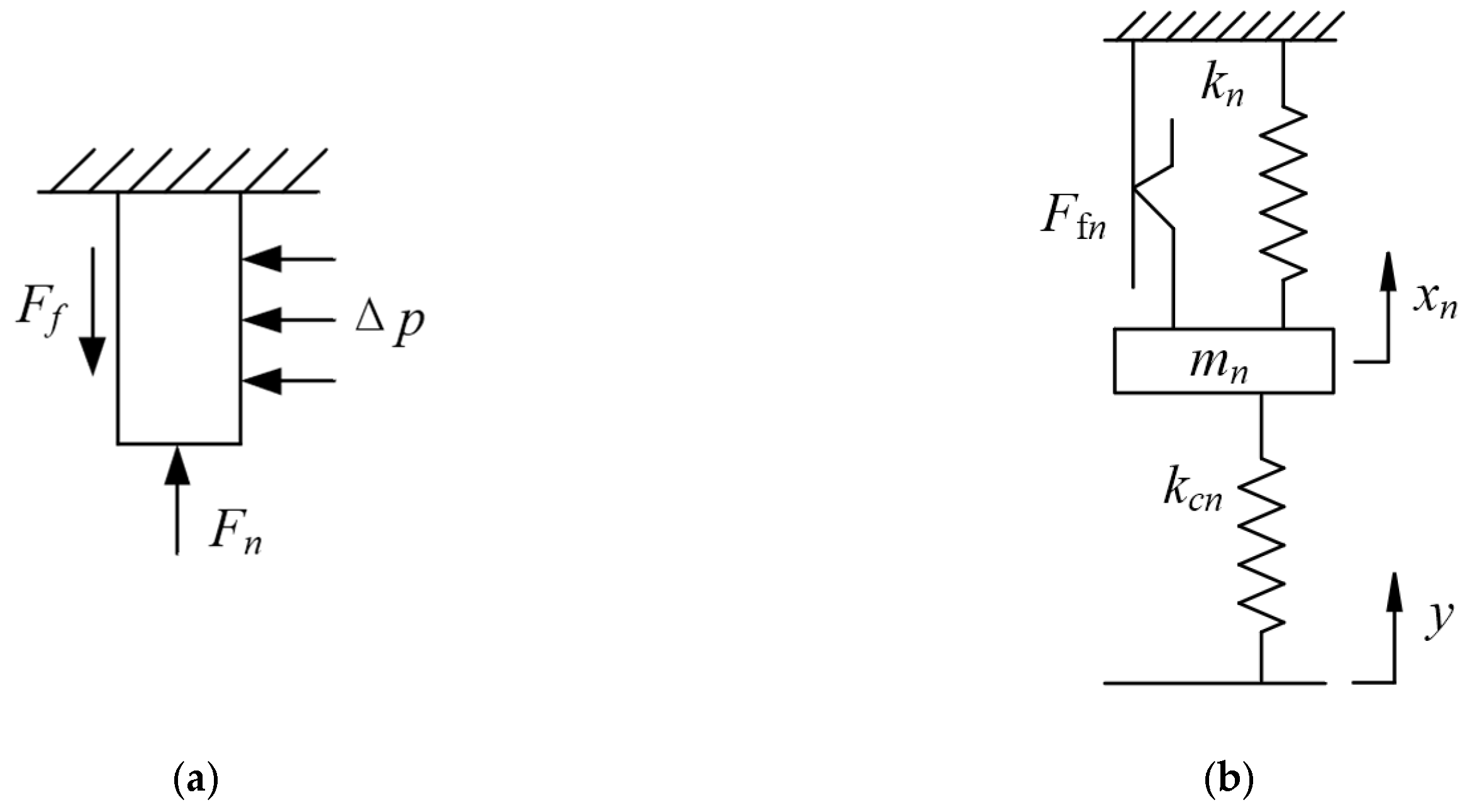
Since the finger laminates are axially clamped between the forward and aft cover plates, the axial vibration of the finger beams is negligible compared to their radial vibration. Therefore, the equivalent dynamic model considers only the radial motion of the finger beams. Taking the n-th layer high-pressure finger laminate near the high-pressure side as an example, a single finger beam is subjected to the gas pressure differential Δp. When it is subjected to rotor radial excitation, the finger beam experiences a friction force Ffn from the adjacent (n − 1)-th layer finger laminate. This represents the force condition in the contact state, as shown in Figure 2a. It can be represented by a mass-spring dynamic model, as shown in Figure 2b. Where mn is the equivalent mass of the n-th layer high-pressure finger beam, kn is the equivalent stiffness, Ffn is the Coulomb friction force between the n-th and (n − 1)-th layers, and kcn is the contact stiffness between the rotor and the finger. Similarly, the equivalent models for the finger beams in the intermediate layers and the low-pressure side can be obtained (the difference is that the finger beams on both sides are subjected to friction forces F f i from adjacent layers). Since the tops of the finger beams of each layer are fixed together by the forward and aft cover plates, the mechanical behavior between the multi-layer stacked finger seal and the rotor can be described by the distributed mass equivalent dynamic model illustrated in Figure 3. Here, mi and ki represent the equivalent mass and equivalent structural stiffness coefficient of the i-th layer finger laminate, respectively; Ffi and F f i denote the frictional resistance exerted on the i-th layer finger laminate by adjacent laminates or the aft cover plate; xi is the radial displacement of the equivalent mass block of the i-th layer (i.e., the displacement response of the i-th layer finger laminate). As shown in Figure 3a, the equivalent dynamic model when the finger foot/rotor is in contact includes kc, the contact stiffness coefficient between the finger foot and the rotor, and y, the displacement excitation of the rotor. In this state, the finger seal system undergoes damped forced vibration. Figure 3b illustrates the equivalent dynamic model when the finger foot/rotor is in a disengaged state, where the finger seal experiences damped free vibration.
The differential equations for the equivalent dynamic system of the finger seal can be established based on Newton’s law. For the damped forced vibration of the finger seal when the finger foot/rotor is in contact (Figure 3a), the derived differential equation is shown in Equation (1).
m i x ¨ i = k i x i + k c i ( y i x i ) + F f i + F f i                       1 i n 1 m i x ¨ i = k i x i + k c i ( y i x i ) + F f i                                               i = n  
For the damped free vibration of the finger seal after the finger foot/rotor disengages (Figure 3b), the derived differential equation is presented in Equation (2).
m i x ¨ i = k i x i + F f i + F f i                       1 i n 1 m i x ¨ i = k i x i + F f i                                               i = n
In the above equations, n represents the number of finger laminate layers; xi denotes the displacement response of the i-th layer finger laminate (radial displacement of the equivalent mass block); y indicates the rotor displacement excitation; mi is the equivalent mass of the i-th layer finger laminate; ki represents the equivalent structural stiffness coefficient of the i-th layer finger laminate; kci is the contact stiffness coefficient between the i-th layer finger laminate and the rotor; Ffi and F f i refer to the frictional resistance acting on the i-th layer finger laminate from adjacent laminates or the aft cover plate, satisfying the relation given in Equation (3).
F f i = F f i       2 i n

3.2. Equivalent Mass

The mass of each finger laminate primarily consists of the mass of its finger feet and finger beams. In the equivalent dynamic model of the finger seal, the mass of the finger feet and finger beams of each laminate is represented as an equivalent mass block, thereby reducing the mass of the multi-layer stacked finger seal system to multiple distributed equivalent mass blocks. Based on the principle that the kinetic energy of the equivalent mass equals the sum of the kinetic energies of the finger beams and finger feet, the calculation formula for the equivalent mass mi is derived as shown in Equation (4) [17].
m i = m f + 0 l ρ h δ x 2 z d z
where mf denotes the mass of the finger feet; ρ represents the density of the finger seal material; δ refers to the width of the finger beams; h indicates the thickness of the finger laminate; l is the length of the finger beams; and x(z) represents the dimensionless static displacement at any point on the finger beams.

3.3. Contact Stiffness Coefficient Between the Finger Foot and the Rotor

In the equivalent dynamic model for the finger foot/rotor contact state, the contact condition is represented by the deformation of a spring with a stiffness coefficient kc. The contact stiffness coefficient kc between the finger foot and the rotor is influenced by factors such as their geometric dimensions, material properties, and surface roughness. This study establishes a rough surface-rigid surface contact model and performs finite element contact analysis on a cuboid element with a rough surface to determine the contact stiffness coefficient kc between the finger foot and the rotor [23].
k c = A f A a k
where Aa represents the contact area between the cuboid model with a rough surface and the rigid plane; Af denotes the contact area between the finger seal and the rotor; and k refers to the stiffness coefficient of the homogeneous spring in the equivalent system. The cuboid model with a rough surface is decomposed into a smooth cuboid of identical length and a roughness layer with negligible thickness. The surface roughness of the rough contact interface is Ra = 0.4 μm. The stiffness coefficient k can be expressed as:
k = k s k R k s k R
k s = E A l
where ks represents the stiffness coefficient of the smooth body; A denotes the cross-sectional area of the smooth cuboid; l is its axial length; E refers to the elastic modulus of the smooth cuboid material; and kR is the contact stiffness coefficient of the rough surface, obtained through finite element contact analysis of the rough surface.

3.4. Frictional Resistance of Finger Seal System

The pressurized gas in the high-pressure cavity generates contact pressure between the aft cover plate/finger laminates and between adjacent finger laminates of the finger seal. When the finger beams undergo radial motion, this contacting pressure induces frictional resistance (Coulomb friction) that hinders the radial deformation of the finger beams.
The frictional resistance Ff1 between the aft cover plate and the first layer finger laminate (as shown in Figure 3) is expressed as:
F f 1 = F s 1 sgn ( F 1 )                           F 1 F s 1 , Δ x ˙ 1 t ε             F 1                                         F 1 < F s 1 , Δ x ˙ 1 t ε   F d 1 sgn ( F 1 )                                             o t h e r s
where ε is a velocity threshold value considered sufficient for static conditions, taken as 10−4 m/s based on the author’s computational experience; Δ x ˙ 1 t is the radial velocity difference between the aft cover plate and the finger laminate, i.e., the velocity of the first layer finger laminate; Fs1 is the static friction force between the aft cover plate and the finger laminate; Fd1 is the dynamic friction force between the aft cover plate and the finger laminate; and F1 is the resultant force acting on the first layer finger laminate in the radial direction, excluding the frictional resistance Ff1.
The frictional resistance Ff(i+1) between the i-th layer and the (i + 1)-th layer finger laminates (as shown in Figure 3) can be expressed as:
F f i + 1 = F s i + 1 sgn ( F i + 1 ) F i + 1 F d i + 1 sgn ( Δ x ˙ i + 1 ( t ) )         F i + 1 F s i + 1 , Δ x ˙ i + 1 t ε F i + 1 < F s i + 1 , Δ x ˙ i + 1 t ε others           1 i n 1
where Δ x ˙ i + 1 t is the radial velocity difference between the i-th and (i + 1)-th layer finger laminates; Fs(i+1) is the static friction force between the i-th and (i + 1)-th layer finger laminates; Fd(i+1) is the dynamic friction force between the i-th and (i + 1)-th layer finger laminates; and Fi+1 is the resultant force acting on the (i + 1)-th layer finger laminate in the radial direction, excluding the frictional resistance Ff(i+1).
The formulas for calculating the static and dynamic friction forces between the finger laminates and the aft cover plate, as well as between adjacent finger laminates, are as follows:
F s i + 1 = f s l P A l t
F d i + 1 = f d l P A l t
where fsl and fdl represent the static and dynamic friction coefficients between the aft over plate and the finger laminate (l = 1) and between adjacent finger laminates (l = 2), respectively; Al(t) denotes the contact area between the aft cover plate and the finger laminate (l = 1) or between adjacent finger laminates (l = 2) at time t.
For the finger foot/rotor contact state, Fi+1 is expressed as:
F i + 1 = k i + 1 x i + 1 + k c y x i + 1 F f i + 2                 1 i n 2 k i + 1 x i + 1 + k c y x i + 1                                                 i = n 1
For the finger foot/rotor disengagement state, Fi+1 is expressed as:
F i + 1 = k i + 1 x i + 1 F f i + 2                 1 i n 2 k i + 1 x i + 1                                               i = n 1
where n is the number of finger laminate layers; ki represents the equivalent structural stiffness coefficient of the i-th layer finger laminate; kc is the contact stiffness coefficient between the finger foot and the rotor; xi denotes the displacement of the i-th layer finger laminate; y indicates the rotor displacement excitation; and Ff(i+2) represents the frictional resistance between the (i + 1)-th and (i + 2)-th layer finger laminates, determined by Equation (9).
Equations (8)–(13) form a recursive process for calculating the frictional resistance in the equivalent dynamic model of the finger seal.

3.5. Equivalent Structural Stiffness Coefficient

Taking a single finger beam as the research object, the influence of thermal effects is considered, and a thermo-structural coupling analysis method is adopted to calculate the average deformation Δx of the finger foot under the action of a radial force ΔF. According to Hooke’s law, the equivalent structural stiffness coefficient k of a single finger beam is obtained as:
k = F x
The content related to thermal analysis is presented in Section 4.

3.6. Displacement Excitation of the Rotot

In the equivalent dynamic model, the rotor displacement excitation acts on the finger foot. Due to the thermal deformation of the rotor in a high-temperature environment, the influence of thermal deformation should be considered in the actual displacement excitation acting on the seal foot. The calculation formula for the rotor displacement excitation considering thermal effects is:
y = Δ r sin ( ω t ) ( e 0 e r e f )
where Δr is the radial runout of the rotor, ω is the angular velocity of the rotor, er is the thermal deformation of the rotor, ef is the thermal deformation of the finger seal, and e0 is the initial installation clearance.

4. Thermal Analysis Model and Boundary Conditions for Finger Seal

To calculate the structural stiffness of finger laminates and the thermal deformation of the rotor and finger seal under thermal effects, a thermo-structural coupling analysis of the finger seal is required.

4.1. Structural Model and Thermal Boundary Conditions of Finger Seal System

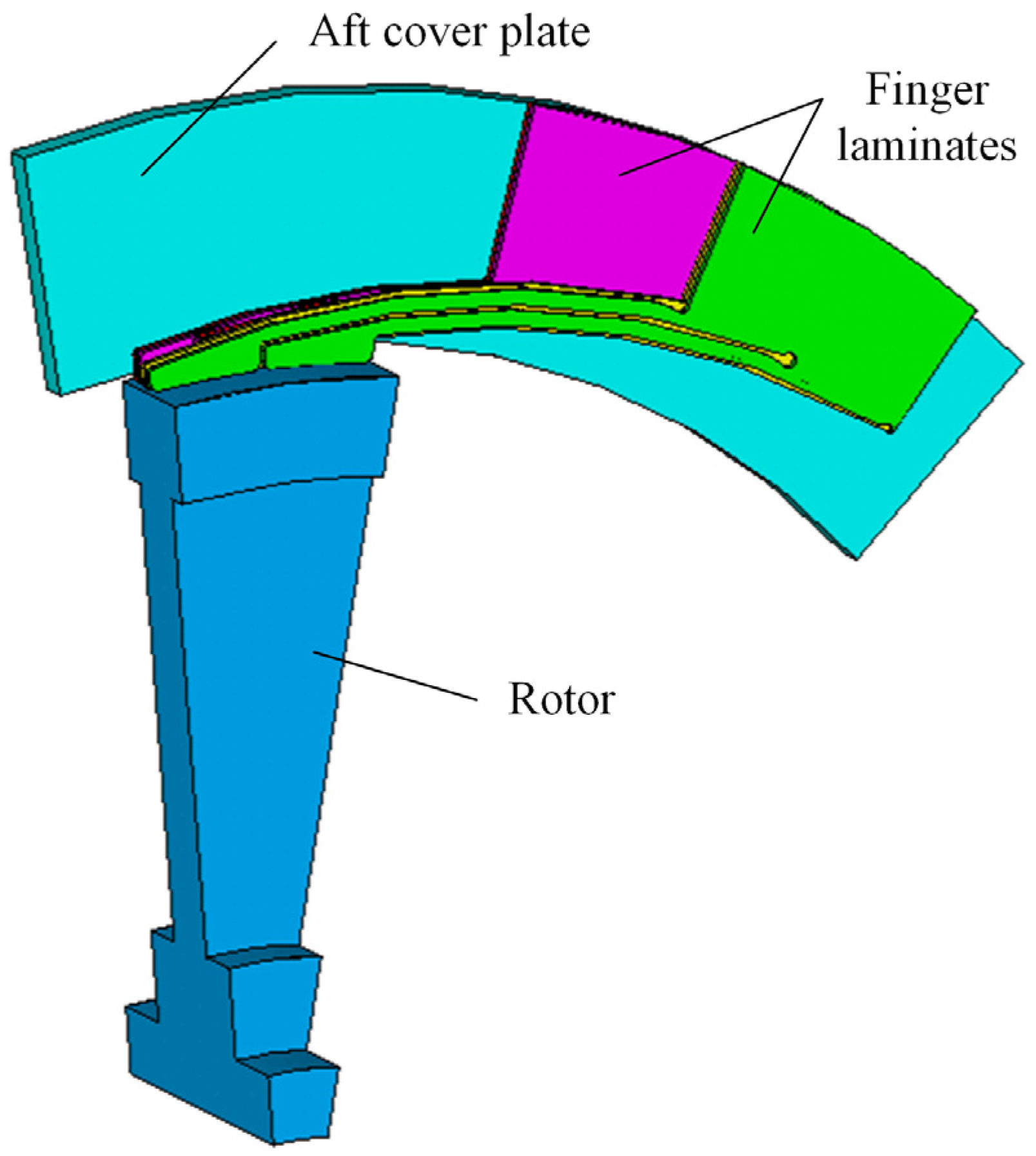
This study employs the finite element method for thermo-structural coupling analysis of the finger seal system to determine the temperature distribution of finger laminates and the thermal deformation of the finger seal and rotor. A structural model comprising five layers of finger laminates, a rotor, and an aft cover plate is established, as shown in Figure 4. When calculating the thermal deformation of the finger seal, fully fixed constraints are applied to the outer circumferential surface of the finger laminates, the side surfaces of the laminates, and the aft cover plate. Axial constraints are applied to the front and rear end surfaces of the rotor. The pressure difference between the high-pressure and low-pressure cavities is applied to the upstream surface of the high-pressure-side finger laminates.
The thermal boundary conditions for the finger seal system are as follows:
(1) Convective heat transfer: This includes heat exchange between the circumferential surface of the rotor and the gas in the high/low-pressure cavities, between the rotor end faces and the gas in the cavities, and between the high/low-pressure-side seal laminates and the cavity gas.
The convective heat transfer coefficients for the rotor circumferential surface interacting with the high/low-pressure cavity gas, the finger laminates interacting with the high-pressure cavity gas, and the aft cover plate interacting with the low-pressure cavity gas can be calculated using the fluid flow over a flat plate heat transfer model. The formula for the convective heat transfer coefficient is [24]:
α =         0.664 K l P r 1 3 R e l 1 2 R e l < 5 × 1 0 5 0.037 R e l 0.8 850 K l P r 1 3                                 5 × 1 0 5 R e l < 1 0 7
where l is the characteristic length. The characteristic lengths for calculating the convective heat transfer coefficients between the rotor circumferential surface and the high/low-pressure cavity gas, between the finger laminates and the high-pressure cavity gas, and between the aft cover plate and the low-pressure cavity gas are πDr, (DeDr)/2, and (DwDr)/2, respectively. The Reynolds number R e l = π D r V ν , kinematic viscosity ν, thermal conductivity K, and Prandtl number Pr are functions of gas temperature:
K = 2.78 × 1 0 8 t 2 + 8.03 × 1 0 5 t + 0.02
ν = 7.36 × 1 0 11 t 2 + 9.53 × 1 0 8 t + 1.3 × 1 0 5
P r = 2.87 × 1 0 10 t 3 + 5.53 × 1 0 7 t 2 2.48 × 1 0 4 t + 0.7
The convective heat transfer coefficient between the rotor end faces and the high/low-pressure cavities can be expressed as [24]:
α = 1.17 K R e r 0.5 D r 0.6 / P r + 0.95 / P r 1 3 R e r 2.4 × 1 0 5 0.042 K R e r 0.8 P r 1 3 D r R e r 2.4 × 1 0 5
where the rotational Reynolds number Rer = DrV/(2ν), Dr is the rotor diameter.
(2) Contact Thermal Conductance: Heat conduction includes internal heat transfer within components and contact heat transfer between finger laminates, between finger laminates and the aft cover plate, and between finger feet and the rotor. The formula for calculating the contact thermal conductance in the finger seal system is given by [25]:
h c = 1.55 p f E 2 ϕ S 0.94 ϕ S k s σ s
where Pf is the average contact pressure between two interacting surfaces, obtained through finite element calculations; φ s represents the equivalent asperity slope angle of the contact surfaces, expressed as φ s = φ a 2 + φ b 2 , where φ a and φ b are the asperity slope angles of the two contacting surfaces, with values referenced from [26]; ks is the equivalent thermal conductivity of the two contacting surfaces, calculated as k s = 2 k a k b k a + k b , where ka and kb are the thermal conductivities of the materials of the contacting parts; σs is the equivalent surface roughness of the contact surfaces, given by σ s = σ a 2 + σ b 2 , where σa and σb are the roughness values of the two contacting surfaces (in this study, σa = σb = 0.4 μm); and E′ is the equivalent elastic modulus, calculated as:
1 E = 1 ν A 2 E A + 1 ν B 2 E B
In the formula, EA and EB represent the elastic moduli of the two different materials, respectively, while νA and νB denote the Poisson’s ratios of the corresponding contact pair materials.
(3) Heat Flux Density: The frictional heat generated when the finger foot bottom surface contacts the rotor outer surface is transferred to the two contacting surfaces in the form of heat flux density. The heat flux qf on the finger foot bottom surface and the heat flux qr on the rotor surface are calculated as:
q f = π n D r μ p k p 60
q r = π n D r μ p 1 k p 60
where μ is the friction coefficient between the finger laminate and rotor materials; Dr is the rotor diameter, n is the rotor rotational speed (unit: r/min); p is the equivalent contact pressure between the finger pad and the rotor (unit: MPa); and kp is the heat partition coefficient. Since the finger laminate and rotor are made of the same material, kp is taken as 0.5.

4.2. Fitting Formula for Equivalent Structural Stiffness Considering Thermal Effects

In engineering applications, the finger seal operates in a high-temperature environment. The high temperature causes thermal deformation of the finger seal system, resulting in changes in the radial clearance between the finger foot bottom surface and the rotor outer surface, which consequently affects the sealing performance. Therefore, the finger seal working station exhibits typical characteristic of thermo-structural coupling. The finite element method is employed to perform thermo-structural coupling analysis to calculate the structural stiffness of the finger beams. First, a temperature field analysis of the finger seal is conducted to obtain the temperature distribution of the finger seal system. Then, the temperature is applied as a load to the structural model to calculate the thermal deformation of the finger and rotor, er and ef, which are used to correct the gap between the rotor and the finger. Subsequently, based on this, a radial force ΔF is applied to the bottom of the finger pad, and the average displacement Δx of the finger foot is calculated. Substituting into Equation (14), the structural stiffness of the finger beam can be calculated.
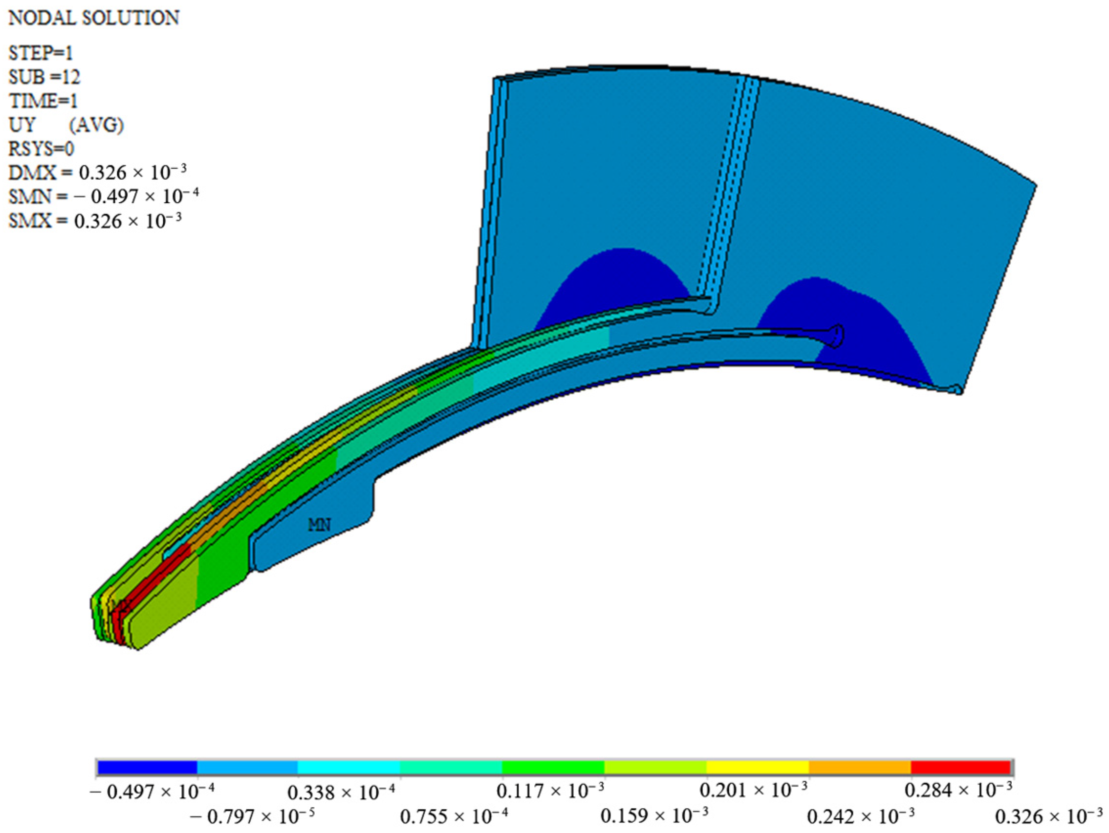
Figure 5 and Figure 6 show the temperature distribution and thermal deformation of the 3Y+2X finger laminates region at a rotational speed n of 15,000 r/min, a pressure differential Δp of 0.3 MPa, a displacement excitation amplitude of 0.05 mm, and a temperature of 100 °C. It can be seen that the temperature at the finger feet is relatively high, and the deformation is also quite significant.
To facilitate calculation, the structural stiffness of the finger beams was calculated under different pressure difference and temperature conditions. The functional relationships between the structural stiffness Kxt, Kyt of the X-type and Y-type finger beams and the temperature Ti at the bottom of the finger foot in the disengaged state are fitted as follows:
k x t = 2.335 × 1 0 4 T i 2 1.3173 T i + 1743.6979
k y t = 3.7989 × 1 0 5 T i 2 0.1211 T i + 509.18468
The functional relationships between the structural stiffness Kxj, Kyj of the X-type and Y-type finger beams and the temperature Ti at the bottom of the finger foot the contact pressure Pi in the engaged state are fitted as follows:
k x j = 2.03072 × 1 0 4 T i 2 1.5352 × 1 0 9 P i 2 + 2.28897 × 1 0 6 T i P i 2.29119 T i + 0.00179 P i + 1389.60108
k y j = 1.44022 × 1 0 4 T i 2 2.90908 × 1 0 10 P i 2 + 3.0414 × 1 0 7 T i P i 0.34706 T i + 3.34562 × 1 0 4 P i + 446.63672

5. Calculation Method for Dynamic Leakage Rate and Rubbing Force

5.1. Dynamic Leakage Rate

During the operation of the finger seal system, a radial clearance is generated between the multilayer finger laminates and the rotor due to the hysteresis effect, forming the main leakage path of the finger seal. The leakage gap between the finger feet and the rotor is characterized by the difference between the displacement response of the finger beams and the displacement excitation of the rotor. Specifically, the leakage gap hi(t) between the finger beams of the i-th laminate and the rotor at time t is expressed as:
h i t = x i t y i t
where xi(t) and yi(t) are the displacement response of the finger beams of the i-th laminate and the corresponding rotor displacement excitation at time t, respectively. The former is obtained by solving Equations (1) and (2), and the latter is provided by Equation (17).
The mass leakage rate of the finger seal is calculated using the empirical formula shown in Equation (30) [27]:
q = 0.887 π D r + 2 Δ S Δ S ρ Δ P
where Dr is the rotor diameter, ΔS is the average clearance of the five laminates, ρ is the density of the sealing medium, and Δp is the pressure differential. In the analysis presented in this paper, the gaps between the finger beams of each laminate and the rotor are first obtained by solving the equivalent dynamic model. The dynamic leakage gaps of the five laminates over a stable period are then processed to obtain the average leakage gap, which is subsequently used to calculate the mass leakage rate of the finger seal system.
It should be noted that, at the microscopic scale, the surface roughness effect and elastic deformation can alter the morphology and distribution of the interface gap, thereby influencing leakage [28]. Since the finger seal studied in this paper is a flexible structure, when the finger laminates contact the rotor, the macroscopic elastic deformation of the finger beams is significantly greater than the microscopic deformation at the interface. Consequently, the gaps leading to leakage in the finger seal are primarily those generated by the macroscopic elastic deformation of the finger beams and the frictional hysteresis, which constitute the main leakage paths. Therefore, the effect of microscopic deformation from rough surface contact on leakage is not considered here.

5.2. Rubbing Force

For a single finger beam, the rubbing force Fri between the finger foot and the rotor is the vector sum of the normal contact force Fni between the finger/rotor interface and the tangential friction force Fti (Coulomb friction force) between the rotor and the bottom of the finger foot. Its calculation formulas are given by Equations (31)–(33). The rubbing force significantly influences the wear and structural strength of the finger seal. Simultaneously, it also affects the rotor’s motion, making it a critical parameter in the dynamic analysis of the rotor-seal system.
F n i t = k i x i ( t ) + F f i F f i k i x i ( t ) + F f i         1 i n 1 i = n
F t i = f F n i
F r i = F n i 1 + f 2 0.5
where ki is the equivalent structural stiffness coefficient of the i-th finger laminate; xi is the displacement response of the i-th finger laminate during the contact process between the finger beam and the rotor; Ffi and F f i are the frictional resistance forces acting on the i-th finger laminate from adjacent laminates or the aft cover plate, determined using the method described in Section 3.4; f is the friction coefficient between the finger laminate and the rotor, which is determined experimentally based on operating conditions such as thermal load, varying within a range of 0.6 to 0.8 for environmental temperatures from room temperature to 300 °C [29].

6. Results and Discussion

The equivalent parameters at room temperature, calculated using the method described in Section 3, are shown in Table 2.
The equivalent structural stiffness coefficient considering thermal effects, calculated using the method described in Section 4, is shown in Table 3.

6.1. Leakage and Rubbing Force Under Different Configurations

The equivalent dynamic model is adopted to calculate the dynamic displacement responses of each layer of the finger laminate after being excited by the rotor. As shown in Figure 7, it is the displacement response of the 3Y+2X type finger seal (rotational speed n is 26,000 r/min, pressure differential Δp is 0.1 MPa, rotor radial runout Δr is 0.05 mm, and temperature is 20 °C). From the low-pressure side to the high-pressure side, the finger laminates are sequentially labeled as Layer 1 to Layer 5. It can be observed that due to the hysteresis effect, the displacements of each layer of finger laminates are different. When the rotor moves upward, the finger slices move upward accordingly. When the rotor descends, the frictional forces between the finger laminates and between the finger and the aft cover plate prevent the reset of the finger beam, resulting in the so-called hysteresis phenomenon. The radial clearance between the first layer of finger plates and the rotor is the largest, while the radial clearance between the fifth layer of finger slices and the rotor is the smallest. This is because the first layer of finger slice has the greatest frictional resistance when in contact with the fixed aft plate, thus resulting in the largest hysteresis gap. The fifth layer is only subjected to the frictional resistance from the adjacent fourth layer of finger slices, so the hysteresis gap is the smallest.
The displacement responses of the other finger seal configurations are similar to that of the 3Y+2X type. At the initial stage of the first cycle, the rotor and finger beams make direct contact and begin to rise. The displacement response stabilizes during the second and third cycles, and data from the third cycle are used for all subsequent analysis.
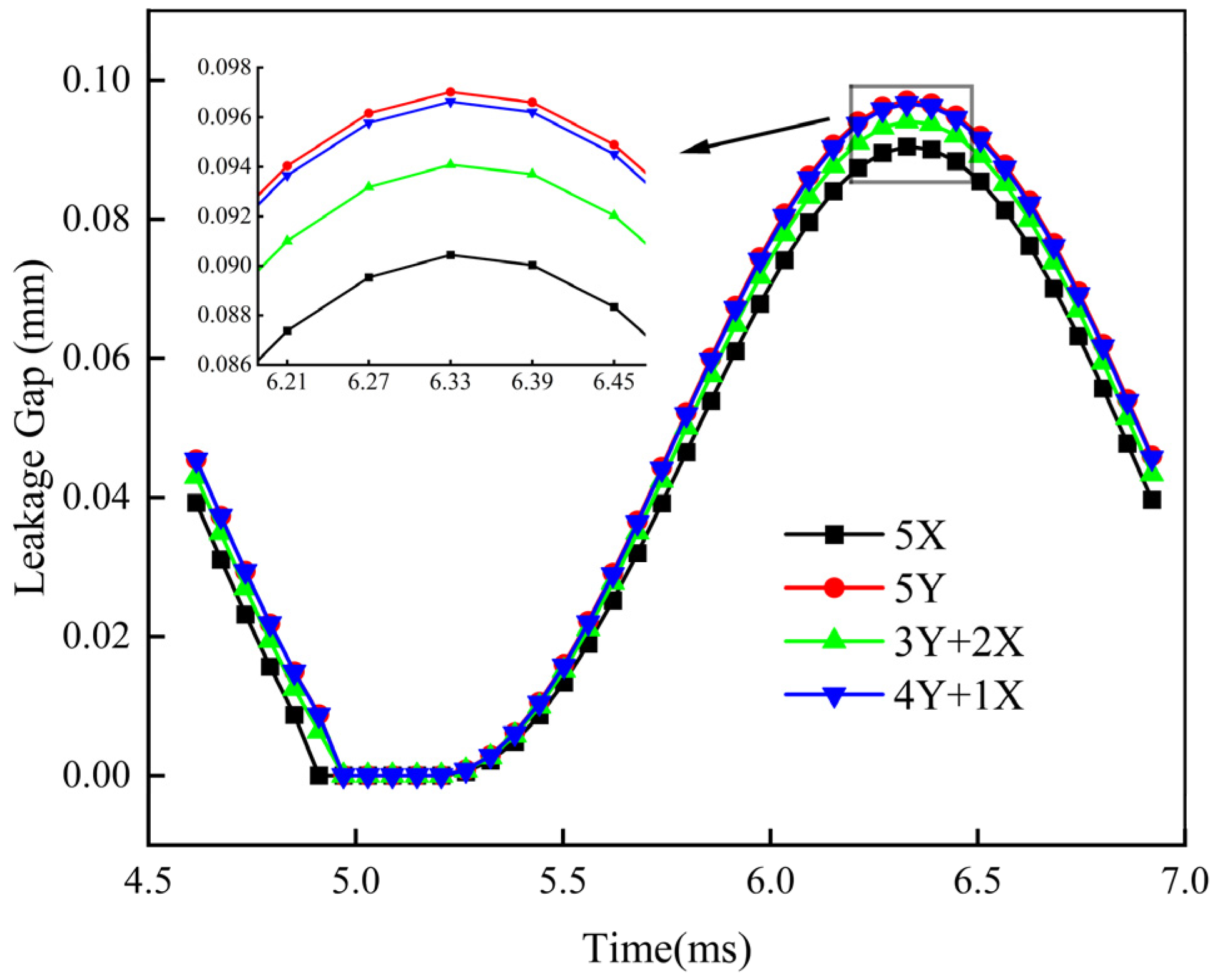
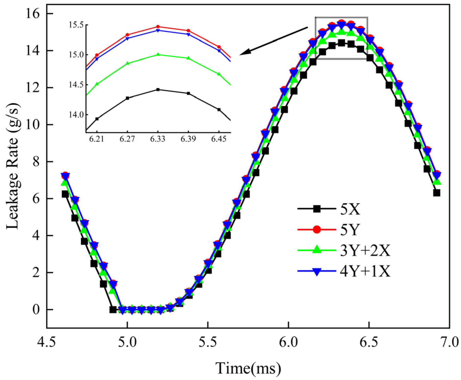
The leakage gaps and leakage rates for four different finger seal configurations are shown in Figure 8 and Figure 9, respectively. The leakage gap for each configuration is obtained by averaging the gaps between the five finger beams of that structure and the rotor. It can be seen that the variation pattern of the leakage gap and leakage rate within the third cycle is consistent for all four finger seal structures, following a decrease-increase-decrease pattern. In the first quarter of the cycle, the rotor’s displacement excitation is in the rising phase; thus, the clearance between the finger feet and the rotor decreases, leading to a decrease in the leakage rate. After the finger laminates contact the rotor, the rotor rapidly descends. Due to the hysteresis characteristic of the finger seal, the displacement response lags behind the rotor, causing the clearance between the finger feet and the rotor to rapidly increase, and the leakage rate consequently increases. In the final quarter of the cycle, as the rotor returns to the zero position before entering the next cycle, the finger laminates tend to stabilize due to frictional forces, and the leakage gap between the finger feet and the rotor tends to decrease.
Observation of the locally magnified view reveals that the order of the dynamic leakage gaps from largest to smallest throughout the cycle for the different finger seal configurations is 5Y > 4Y+1X > 3Y+2X > 5X. This is because the stiffness of the X-type finger laminates is greater than that of the Y-type finger laminates, resulting in less hysteresis and consequently a smaller leakage gap.
The variation in rubbing force for different finger seal configurations is shown in Figure 10. It can be observed that there are differences in the contact time between the various seal configurations and the rotor. Due to the smaller hysteresis of the 5X-type finger seal, its laminates rebound a greater distance within the same time period, thus making contact with the rotor first. Under identical operating conditions, the magnitude of the rubbing force for different configurations follows the same pattern as the leakage gap: the 5Y-type exhibits the largest rubbing force, while the 5X-type exhibits the smallest. The probable reason is that during the contact process between the rotor and the finger laminates, the influence of the finger beam’s elastic force is less significant than that of the frictional force. Furthermore, the X-type laminates used in this study have a smaller axial contact area compared to the Y-type laminates. Under the same conditions, the X-type laminates experience less frictional force, resulting in a lower peak value of the rubbing force.
Although the 5X-type has the smallest peak value of rubbing force, it has the longest contact time with the rotor, which means the cumulative effect of the rubbing force (impulse) is the greatest. The ranking of the impulse of the finger seals from largest to smallest in different combinations is 5X > 3Y+2X > 4Y+1X > 5Y. This is exactly the opposite of the leakage gap rule. The cumulative effect of the rubbing force has an impact on the sealing friction and wear performance. Therefore, when designing, the leakage and rubbing force characteristics of the finger seals should be comprehensively considered.
Comparing the leakage performance and rubbing force of the four various finger seal structures, the 3Y+2X type finger seal demonstrates certain advantages in overall performance. Subsequent research will therefore focus specifically on the 3Y+2X type finger seal.

6.2. Analysis of Operating Condition Effects

6.2.1. Different Pressure Differentials

The influence of four pressure differentials (Δp = 0.1 MPa, 0.15 MPa, 0.2 MPa, and 0.25 MPa) on the dynamic leakage rate and rubbing force of the 3Y+2X finger seal is investigated under the conditions of a rotational speed n of 26,000 r/min, a rotor radial runout Δr of 0.05 mm, and a temperature of 20 °C, as shown in Figure 11 and Figure 12, respectively.
As can be seen from Figure 11, with the increase in pressure difference, the leakage rate of the finger seal gradually increases. The increase in pressure difference will increase the frictional resistance between the sealing laminates, thereby affecting the sealing leakage gap. At the same time, the increase in pressure difference leads to an increase in the pressure flow. The combined effect of these two factors is that the leakage rate increases with the increase in pressure difference.
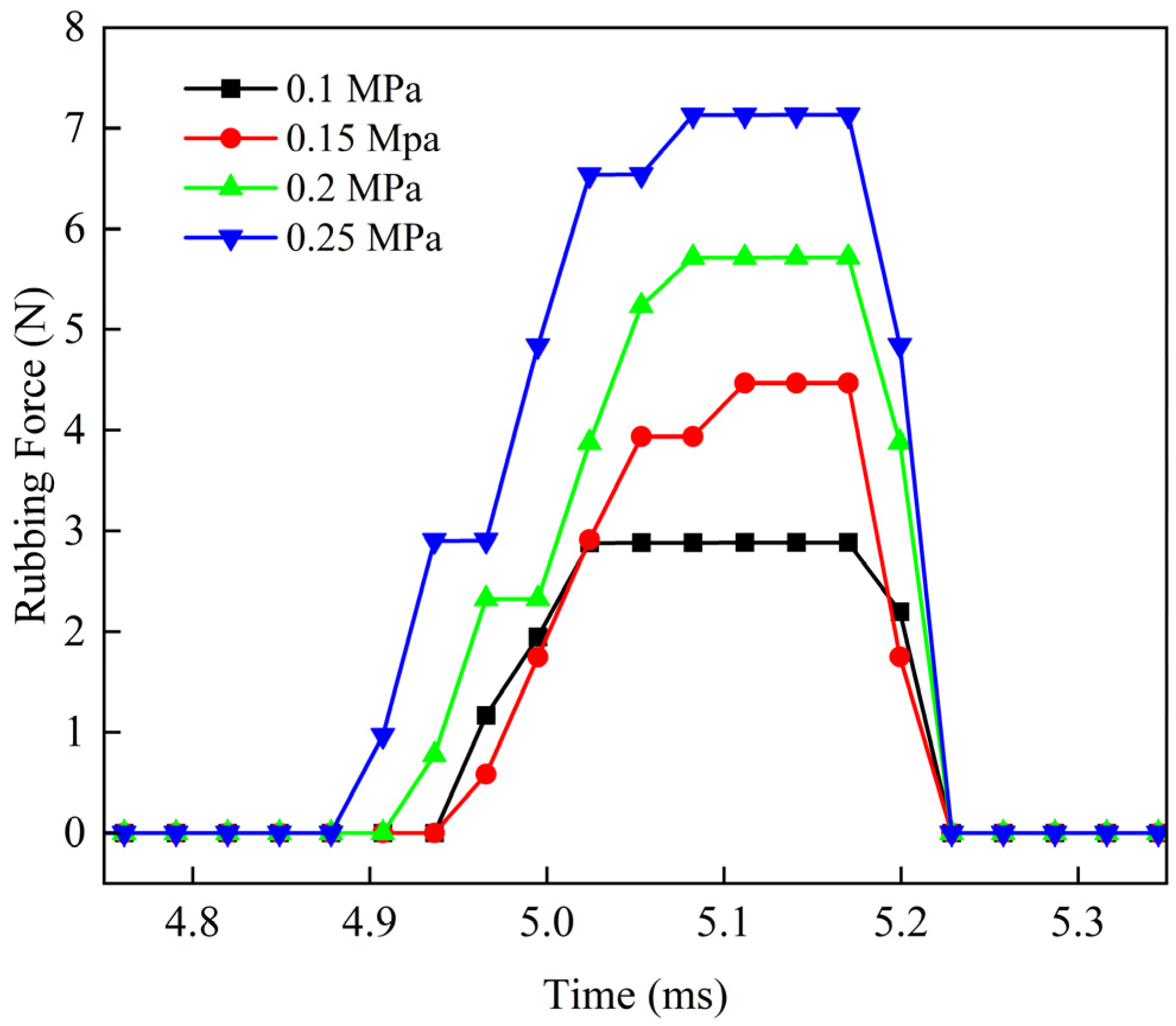
As seen in Figure 12, as the pressure differential increases, the finger seal makes contact with the rotor earlier, the contact duration lengthens, and the rubbing force peak value also increases. Some fluctuations are present in the calculated rubbing force results. The reason for this is that the frictional resistance between the finger laminates themselves and between the laminates and the aft cover plate is piecewise (as shown in Equation (9)), and the value of the friction force depends on the relative motion state of the finger laminates.
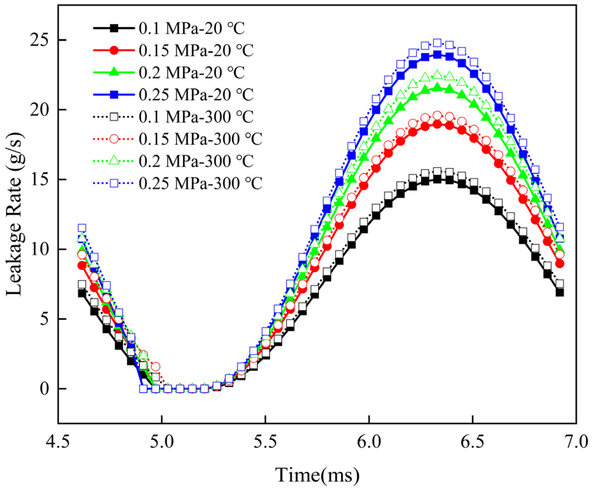
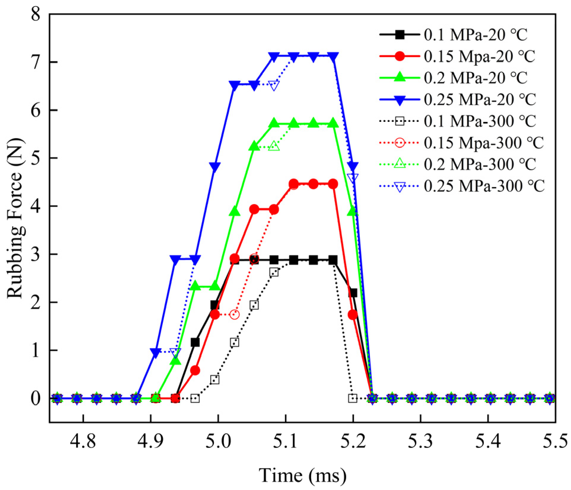
Figure 13 and Figure 14 show a comparison of the calculated results considering thermal effects at a temperature of 300 °C with those at 20 °C, under different pressure differentials while keeping the rotational speed and rotor radial runout constant. It can be observed that the leakage rate increases in the high-temperature environment, while the rubbing force remains relatively close but shows a slight decreasing trend. When the temperature increases, due to the gradual decrease in the structural stiffness of the finger seal when thermal effects are considered (as can be seen in Table 3) and the influence of thermal deformation of the rotor and finger feet on the leakage gap, the hysteresis phenomenon becomes more significant under the same conditions, leading to increased leakage rate and reduced rubbing force.

6.2.2. Different Displacement Excitations

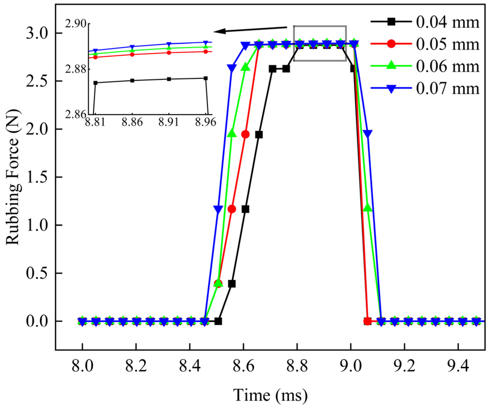
The influence of rotor displacement excitation on the dynamic performance of the 3Y+2X type finger seal is investigated. Analyses of its effects on the leakage rate and rubbing force of the finger seal are conducted under a rotational speed of 15,000 r/min, a pressure differential Δp of 0.1 MPa, and rotor radial runouts Δr of 0.04 mm, 0.05 mm, 0.06 mm, and 0.07 mm, as shown in Figure 15 and Figure 16, respectively.
As can be seen from Figure 15, as the displacement excitation increases, the leakage rate of the finger seal significantly enlarges. The reason is that an increase in rotor displacement excitation extends the rebound distance of the finger beams, thereby increasing the gap between the finger feet and the rotor.
Figure 16 shows the effect of rotor displacement excitation on the rubbing force between the finger beams and the rotor. As the displacement excitation increases, the initial contact time between the finger beams and the rotor occurs earlier, and the contact duration prolongs. Within a single rotor cycle, the amplitude of the rubbing force gradually increases with greater rotor displacement excitation. This is because increasing the rotor displacement excitation necessarily leads to greater deformation of the finger beams, which enhances their rebound force and consequently increases the contact force between the finger feet and the rotor.
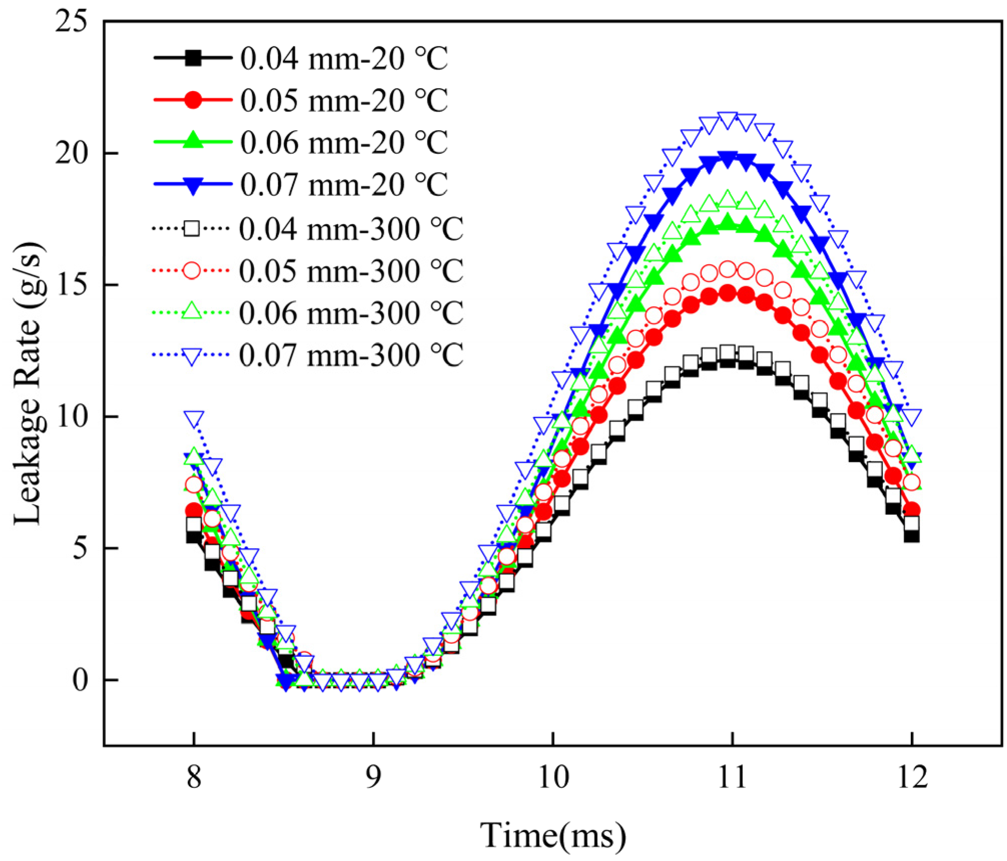
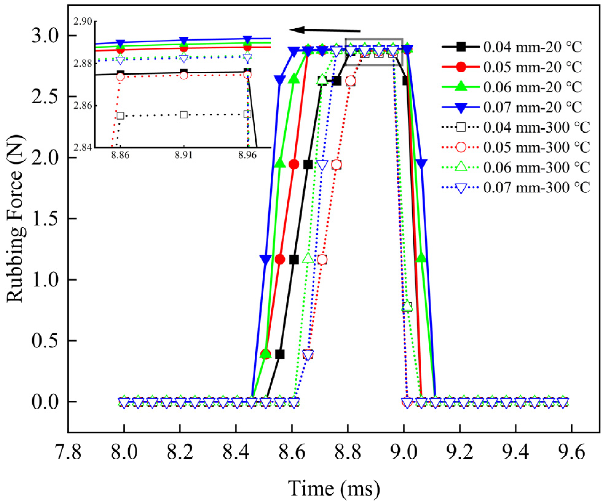
Furthermore, the leakage rate and rubbing force under different displacement excitations are calculated for conditions where the pressure differential and rotational speed remained constant at a temperature of 300 °C. These results are compared with the calculated results at a temperature of 20 °C, as shown in Figure 17 and Figure 18. It can be observed that the leakage rate at high temperature is greater than that under the same operating conditions at room temperature, and the difference between the high-temperature and room-temperature leakage results increases as the displacement excitation increases. Compared with the rubbing force under the same working conditions at normal temperature, the rubbing force at high temperatures not only decreases at its peak value but also shortens the contact time domain. This is because as the temperature increases, the structural stiffness of the finger seal, considering thermal effects, gradually decreases. Under the same conditions, the hysteresis phenomenon becomes more significant, leading to increased leakage and reduced rubbing force. It can be seen that the thermal effect has a significant impact on the sealing performance and cannot be ignored.

6.2.3. Different Temperatures

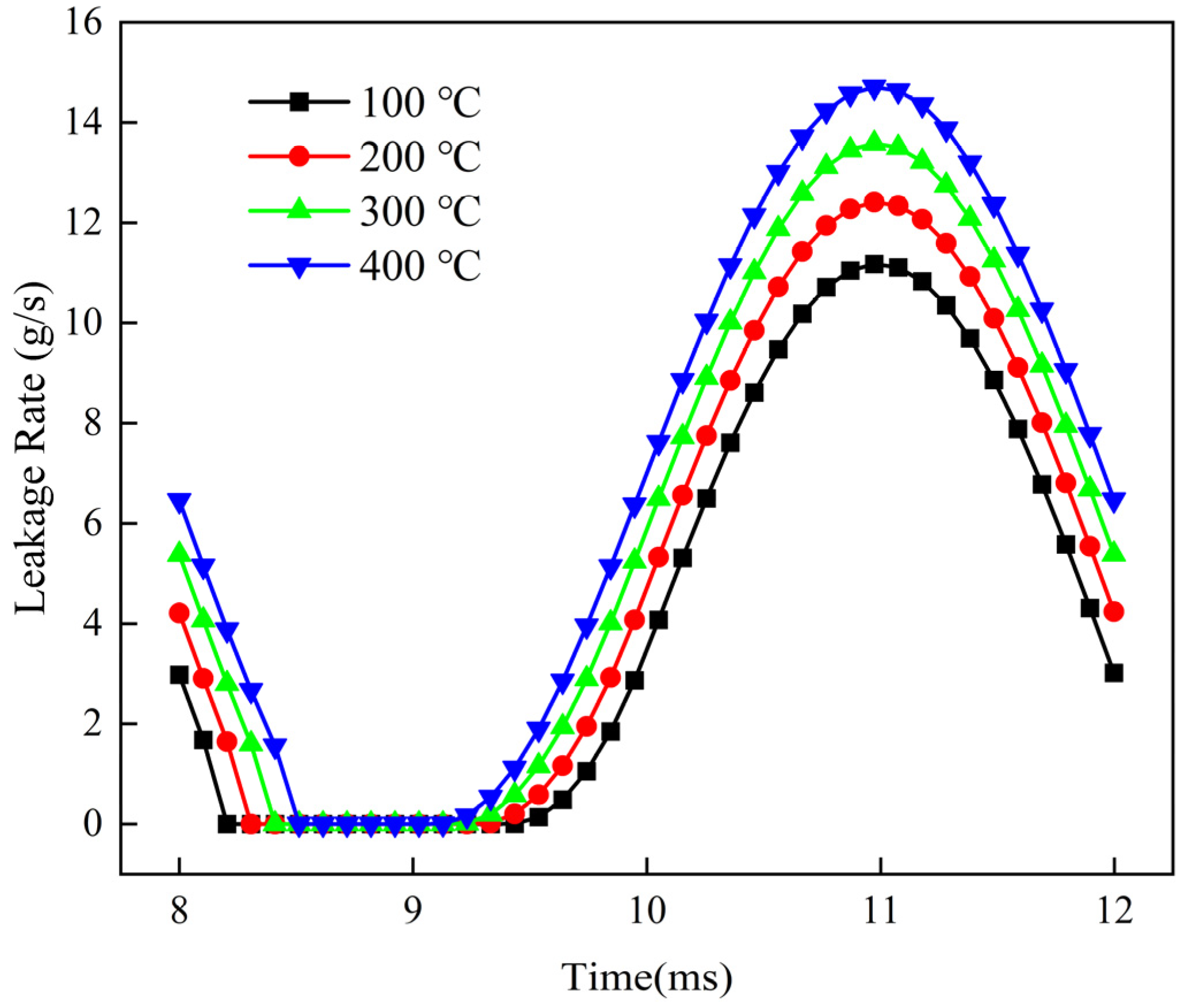
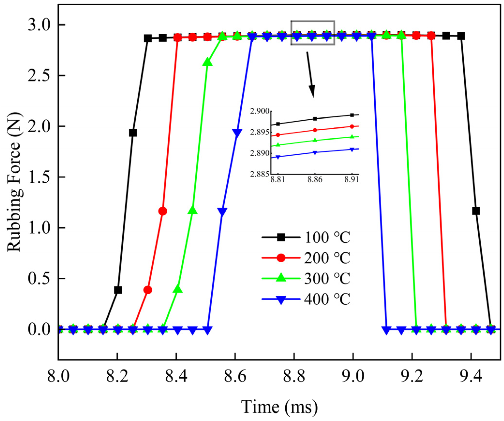
The influence of high-pressure gas temperature on the dynamic performance of the 3Y+2X type finger seal is investigated. Calculations are performed under the conditions of n = 15,000 r/min, Δp = 0.1 MPa, and Δr = 0.05 mm for temperatures of 100 °C, 200 °C, 300 °C, and 400 °C to determine the dynamic leakage and rubbing force.
Figure 19 shows the effect of temperature on the leakage rate between the finger beams and the rotor. As the temperature increases, the leakage rate also increases. This is because the equivalent stiffness of the finger beams decreases with rising temperature, making the hysteresis phenomenon more pronounced. The displacement response of the finger beams after disengagement is reduced, leading to an increase in both the leakage gap and the leakage rate. Simultaneously, the temperature increase also leads to increased thermal deformation of the finger and rotor, thereby affecting the gap between the finger and the rotor, as well as the actual displacement excitation of the rotor (as shown in Equation (14)). Under the combined action of these factors, and for the specific structure and operating conditions calculated in this paper, the result manifests as an increase in leakage with rising temperature.
Figure 20 illustrates the influence of different temperatures on the rubbing force. As the temperature increases, the contact time between the finger feet and the rotor is delayed, and the disengagement time occurs earlier. This is consistent with the aforementioned more significant hysteresis at elevated temperatures. Within the same time period, finger laminates at lower ambient temperatures exhibit higher stiffness and rebound a greater distance, thus making contact with the rotor first and following the rotor for a longer duration after contact. The magnitude of the rubbing force between the finger feet and the rotor is similar across different ambient temperatures. As the temperature increases, the amplitude of the rubbing force shows a gradual decreasing trend. This is because, although the equivalent stiffness of the finger beams decreases with temperature (as shown in Table 3), the increased thermal deformation of the finger beams also leads to a larger contact deformation. Consequently, the rubbing force between the finger beams and the rotor remains relatively close in magnitude across the four temperatures studied herein, with a slightly decreasing trend. Taking into account the cumulative effect of contact time, under the structure and operating conditions of this article, as the temperature rises, the impulse of the seal decreases.

6.3. Comparison of Leakage Performance of Combined Finger Seals

6.3.1. Comparison of Experimental and Computational Results

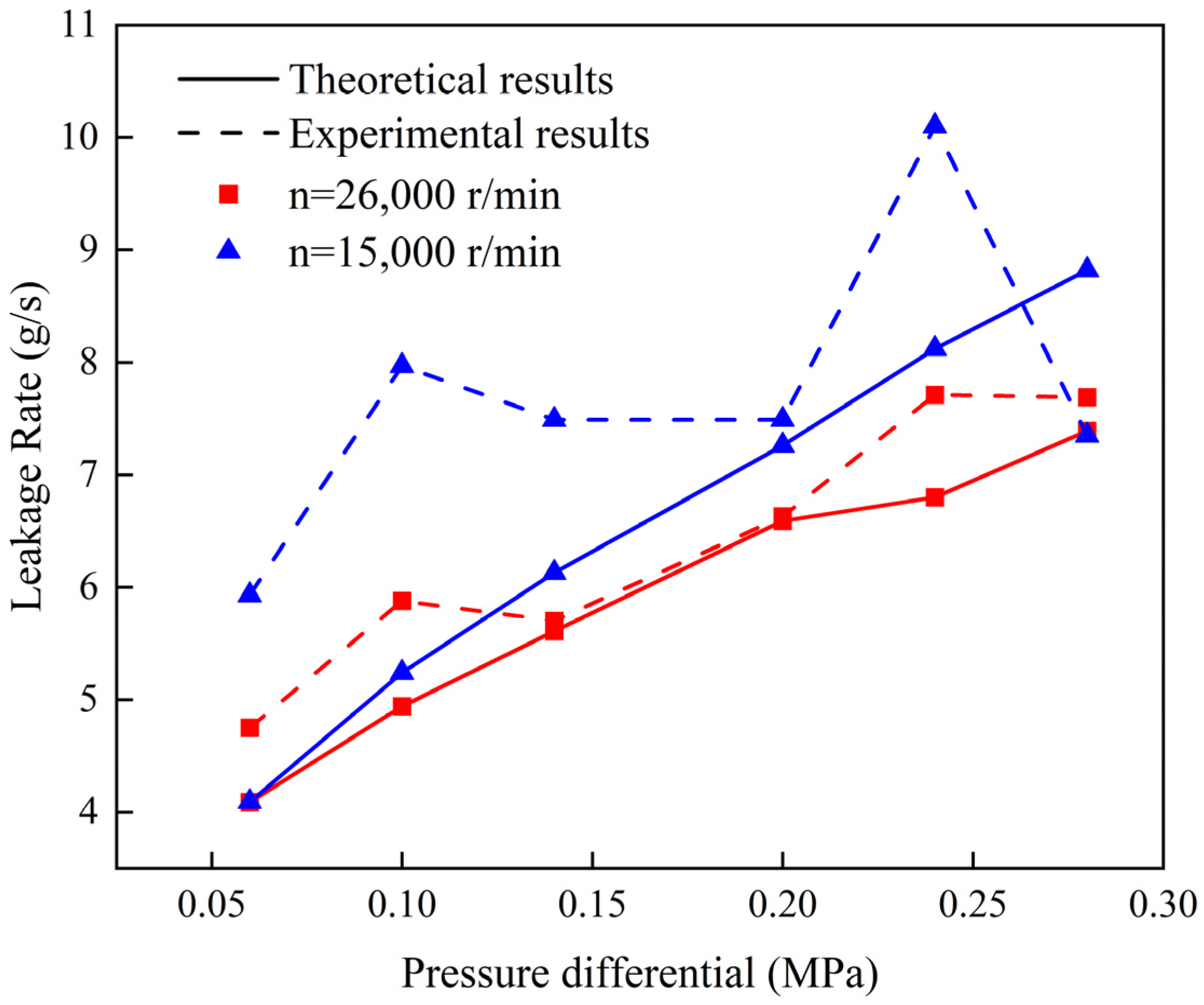
To validate the correctness of the numerical analysis method, experiments on the leakage performance of the finger seal are conducted. Figure 21 shows a comparison between the experimental results and the theoretical results from this study for the leakage rate of the 3Y+2X type combined finger seal under different pressure differentials at a rotational speed of 15,000 rpm and 26,000 rpm and a temperature of 300 °C. A description of the experimental setup can be found in reference [30]. Here, a dynamic model is employed to obtain the average gap of the five-layer finger plate during the stable cycle, and then the leakage rate of the finger seal is calculated based on the average gap.
It can be observed that the calculation results based on the equivalent dynamic analysis show good agreement with the experimental results, demonstrating the effectiveness of the equivalent dynamic analysis model considering thermal effects proposed in this paper. In most cases, the experimental results are slightly larger than the calculated values. This is because the leakage value of the finger seal calculated based on the equivalent dynamic model primarily accounts for leakage generated by the radial clearance, while in reality, there is also circumferential gap leakage between the finger beams due to surface roughness effects or unevenness. Typically, the proportion of circumferential gap leakage is very small [31]. The leakage characteristics of the seal are mainly determined by radial clearance leakage; therefore, the equivalent dynamic model method can be used to evaluate the leakage characteristics of finger seals.

6.3.2. Comparison of Leakage Performance with Other Combined Finger Seals

To illustrate the performance advantages of the 3Y+2X type finger seal adopted in this paper, a comparison is made with the leakage characteristics of the combined finger seals of different beam lengths in reference [21] (referred to as the second-generation finger seal). The maximum dynamic leakage factor of the second-generation finger seal in reference [21] is about 15.6 kgK1/2/MPa-m-s. Under the same working conditions, the maximum dynamic leakage factor of the 3Y+2X type finger seal described in this paper is 11 kgK1/2/MPa-m-s. It can be seen that the leakage rate of the finger seal combination form with different profiles and lengths adopted in this paper is approximately 29% lower than that of the second-generation finger seal described in reference [21], and thus can achieve better sealing performance.

7. Conclusions

(1) The dynamic leakage rate and rubbing force of the 5X, 5Y type finger seal composed of a single form of finger laminate, and the 3Y+2X type and 4Y+1X type finger seals composed of two different forms of finger plate laminate are compared. The dynamic leakage behavior is consistent across different seal configurations. The order of dynamic leakage from largest to smallest throughout the cycle is 5Y > 4Y+1X > 3Y+2X > 5X. During the entire cycle, the order of contact time between the finger feet and the rotor from largest to smallest is 5X > 3Y+2X > 4Y+1X > 5Y. This also determines the sequence of the cumulative effect of the rubbing force. It is exactly the opposite of the order of leakage rate. Therefore, the combined type of finger seal composed of different structural finger laminates has better comprehensive performance.
(2) The leakage characteristics of the 3Y+2X type combined finger seal and the finger seal with different beam lengths (the second-generation finger seal) are compared. The leakage factor of the 3Y+2X type combined finger seal is reduced by 29%.
(3) This paper discusses the dynamic performance of the 3Y+2X structure under various operating conditions from three aspects: pressure differential, displacement excitation, and temperature. Under the structure and operating conditions of this article, as the pressure difference increases, the sealing leakage rate rises, the peak rubbing force increases, and the contact time with the rotor also prolongs. Therefore, the rubbing force impulse also increases. As the displacement excitation increases, the leakage rate of the finger seal increases, the peak value of the rubbing force slightly rises, the contact time between the finger feet and the rotor prolongs, and the rubbing force impulse increases. At a smaller pressure difference, rising temperature leads to a gradual increase in the leakage rate but shortens the contact time and reduces the rubbing force. Among these factors, the influence of the pressure differential on seal performance is relatively complex. Changes in the pressure differential affect both the hysteresis gap of the seal and the pressure-driven flow; the combined effect of these two aspects influences the leakage rate of the seal.
(4) This study conducted a thermo-structural coupling analysis of the finger seal, obtaining the structural stiffness of the finger laminates and the thermal deformation of both the rotor and the fingers under thermal effects. A fitting formula for the equivalent structural stiffness considering thermal effects is established. Under different pressure differences and displacement excitation, the leakage rates and rubbing forces of the finger seal are compared at both 20 °C and 300 °C temperatures. The results show that the leakage rate increases at high temperatures compared to normal temperatures, while the rubbing force decreases. This effect is more pronounced under larger displacement excitation. This is mainly due to the reduction in the stiffness of the sealing structure under high temperatures, which enhances the hysteresis effect, as well as the increase in the thermal deformation of the finger beam and the rotor, thereby altering the gap between the seal and the rotor and the actual displacement excitation of the rotor. The combined effect of these factors influences the leakage rate and rubbing force of the finger seal.

Author Contributions

Conceptualization, H.S.; methodology, H.S. and J.Z.; software, J.Z. and Y.S.; validation, H.S. and J.Z. and K.Z.; writing—original draft preparation, J.Z.; writing—review and editing, H.S. All authors have read and agreed to the published version of the manuscript.

Funding

This research was funded by Aeronautical Science Foundation of China, grant No. 2024Z042053001.

Institutional Review Board Statement

Not applicable.

Informed Consent Statement

Not applicable.

Data Availability Statement

The original contributions presented in this study are included in the article. Further inquiries can be directed to the corresponding author.

Conflicts of Interest

The authors declare no conflicts of interest.

References

  1. Proctor, M.P.; Kumar, A.; Delgado, I.R. High-Speed, High-Temperature Finger Seal Test Results. J. Propuls. Power 2004, 20, 312–318, NASA/TM—2002-211589. [Google Scholar] [CrossRef]
  2. MacKay, C.G.; Wright, E.S. Laminated Finger Seal. U.S. Patent 5071138, 10 December 1991. [Google Scholar]
  3. Arora, G.K.; Proctor, M.P.; Steinetz, B.M.; Delgado, I. Pressure Balanced, Low Hysteresis, Finger Seal Test Results. In Proceedings of the 35th Joint Propulsion Conference and Exhibit, Los Angeles, CA, USA, 20–24 June 1999. NASA/TM-1999-209191. [Google Scholar]
  4. Song, D.; Hua, K.; Cheng, Y.; Du, C.; Zhang, Y.; Jing, Y. Multi-scale modeling and mechanical performance analysis of finger seals with plain woven C/C composite. Sci. Rep. 2024, 14, 24382. [Google Scholar] [CrossRef]
  5. Rajesh, P.; Sharana, B.J. Optimization of finger seal pad design for reducing the leakage between the high-pressure and low-pressure region. J. Tribol. 2024, 41, 68–80. [Google Scholar]
  6. Du, C.; Zhang, Y.; Dong, S.; Cui, Y.; Ji, H. Mathematical calculation method for hysteresis characteristics of arc-shaped finger seal. J. Aerosp. Power 2022, 37, 1587–1596. [Google Scholar]
  7. Zhang, T.; Wang, J.; Liu, M. Effect of Rear Baffle Structure on Leakage Characteristics and Temperature Distribution of Finger Seals. Lubr. Eng. 2024, 49, 136–143. [Google Scholar]
  8. Wei, Y.; Ma, B.; Chen, X.; Xu, F.; Guo, J.; Liu, S.; Dou, W. Analysis of non-contact finger seal force based on deformation of the finger pad. J. Mech. Sci. Technol. 2024, 38, 4721–4732. [Google Scholar] [CrossRef]
  9. Wei, Y.; Ma, B.; Li, Y.; Schröder, K.-U. Numerical analysis of seal force in contacting finger seal. Bull. Pol. Acad. Sci. Tech. Sci. 2025, 73, e153840. [Google Scholar] [CrossRef]
  10. Zhang, S.; Xu, Y.; Zhao, R.; Jiao, Y.; Chen, Z. Dynamic Analysis and Independent High-Order Nonlinear Dynamics of a Rotor-Bearing-Finger Seal System. Int. J. Appl. Mech. 2023, 15, 2350051. [Google Scholar] [CrossRef]
  11. Zhang, Y.; Chen, G.; Shen, X. Analysis of Dynamic Performance and Leakage for Finger Seal. ACTA Aeronaut. Astronaut Ica Sin. 2009, 30, 2193–2199. [Google Scholar]
  12. Braun, M.J.; Pierson, H.M.; Deng, D. Thermofluids Considerations and the Dynamic Behavior of a Finger Seal Assembly. Tribol. Trans. 2005, 48, 531–547. [Google Scholar] [CrossRef]
  13. Marie, H. Dynamic Simulation of Finger Seal-Rotor Interaction Using Variable Dynamic Coefficients. In Proceedings of the 42nd AIAA/ASME/SAE/ASEE Joint Propulsion Conference & Exhibit, Sacramento, CA, USA, 9–12 July 2006. AIAA 2006-4931. [Google Scholar]
  14. Lei, Y.; Chen, G. Finger Seal’s Hysteresis Characteristic Based on Dynamical Model. Chin. J. Mech. Eng. 2007, 43, 122–126. [Google Scholar] [CrossRef]
  15. Ma, X.; Chen, G.; Zhang, Y. Equivalent Dynamic Model of a Padded Finger Seal. Mech. Sci. Technol. Aerosp. Eng. 2008, 27, 1356–1360, 1364. [Google Scholar]
  16. Wang, J.; Xu, W.; Liu, M.; Zhu, S.; Kang, Y.; Song, X.; Gu, D.; Hu, X. Study on Interstage Pressure Equalization of Differential Multi-Stage Finger Seal with Structural Design, Flow and Heat Transfer Characteristics. Aerospace 2024, 11, 874. [Google Scholar] [CrossRef]
  17. Chen, G.; Wang, L.; Yu, Q.; Su, H. Dynamic Analysis of C/C Composite Finger Seal. Chin. J. Aeronaut. 2014, 27, 745–758. [Google Scholar] [CrossRef]
  18. Chen, G.-D.; Lu, F.; Yu, Q.-P.; Su, H. Dynamic analysis of finger seal using equivalent model based on distributed mass method. Proc. Inst. Mech. Eng. Part C-J. Mech. Eng. Sci. 2014, 228, 2992–3005. [Google Scholar] [CrossRef]
  19. Wang, L.-N.; Wang, Y.; Sun, H.-C.; Ren, G.-H.; Sun, L.-C.; Meng, D.-H. Dynamic analysis and experimental verification of the carbon-carbon composite finger seal under complex working states. Proc. Inst. Mech. Eng. Part G-J. Aerosp. Eng. 2019, 233, 2914–2922. [Google Scholar] [CrossRef]
  20. Chen, G.; Su, H.; Zhang, Y. Vaiable-Dimension Construction in the Axial Arrangement of Finger Seal Mechanism. J. Aerosp. Power 2003, 18, 488–491. [Google Scholar]
  21. Gibson, N.E.; Takeuchi, D.; Hynes, T. Second Generation Air-to-Air Mechanical Seal Design and Performance. In Proceedings of the 47th AIAA/ASME/SAE/ASEE Joint Propulsion Conference & Exhibit, San Diego, CA, USA, 31 July–3 August 2011. AIAA 2011-5636. [Google Scholar]
  22. Wang, J.; Zhang, Y.; Cui, Y.; Hu, H.; Zhang, L.; Chen, L. High temperature wear behavior of NiCoCrAlY-Cr2O3-AgMo coating on GH4169 superalloy. Mater. Today Commun. 2023, 35, 105762. [Google Scholar] [CrossRef]
  23. Liu, H.; Liu, Y.; Wang, W. New Equivalent Method for Normal Stiffness of Contact Interface. J. Mech. Eng. 2011, 47, 37–43. [Google Scholar] [CrossRef]
  24. Sun, S. Performance Analysis and Wear Rate Calculation of Finger Seal with Different Radial Stiffness Laminates. Master’s Thesis, Northwestern Polytechnical University, Xi’an, China, 2018. [Google Scholar]
  25. Sridhar, M.R.; Yovanovich, M.M. Thermal Contact Conductance of Tool Steel and Comparison with Model. Int. J. Heat Mass Transf. 1996, 39, 831–839. [Google Scholar] [CrossRef]
  26. Zagtodzki, P. Analysis of Thermomechanical Phenomena in Muti-Disc Clutches and Brakes. Wear 1990, 140, 291–308. [Google Scholar] [CrossRef]
  27. Chen, G.; Su, H.; Zhang, Y. Analysis and Design of Finger Seals; Northwestern Polytechnical University Press Co., Ltd.: Xi’an, China, 2012; 61p. [Google Scholar]
  28. Müller, C.; Müser, M.H.; Carbone, G.; Menga, N. Significance of Elastic Coupling for Stresses and Leakage in Frictional Contacts. Phys. Rev. Lett. 2023, 131, 156201. [Google Scholar] [CrossRef] [PubMed]
  29. Zhang, C. Analysis of the Wear Characteristics and Service Life Prediction of Finger Seal. Master’s Thesis, Northwestern Polytechnical University, Xi’an, China, 2021. [Google Scholar]
  30. Li, N.; Peng, Z.; He, L.; Zhou, K.; Li, Q. Development of High-temperature and High-speed Seal Test Rig of Aeroengine. Lubr. Eng. 2014, 39, 121–123. [Google Scholar]
  31. Zhao, H.; Su, H.; Chen, G. Analysis of Total Leakage of Finger Seal with Side Leakage Flow. Tribol. Int. 2020, 150, 106371. [Google Scholar] [CrossRef]
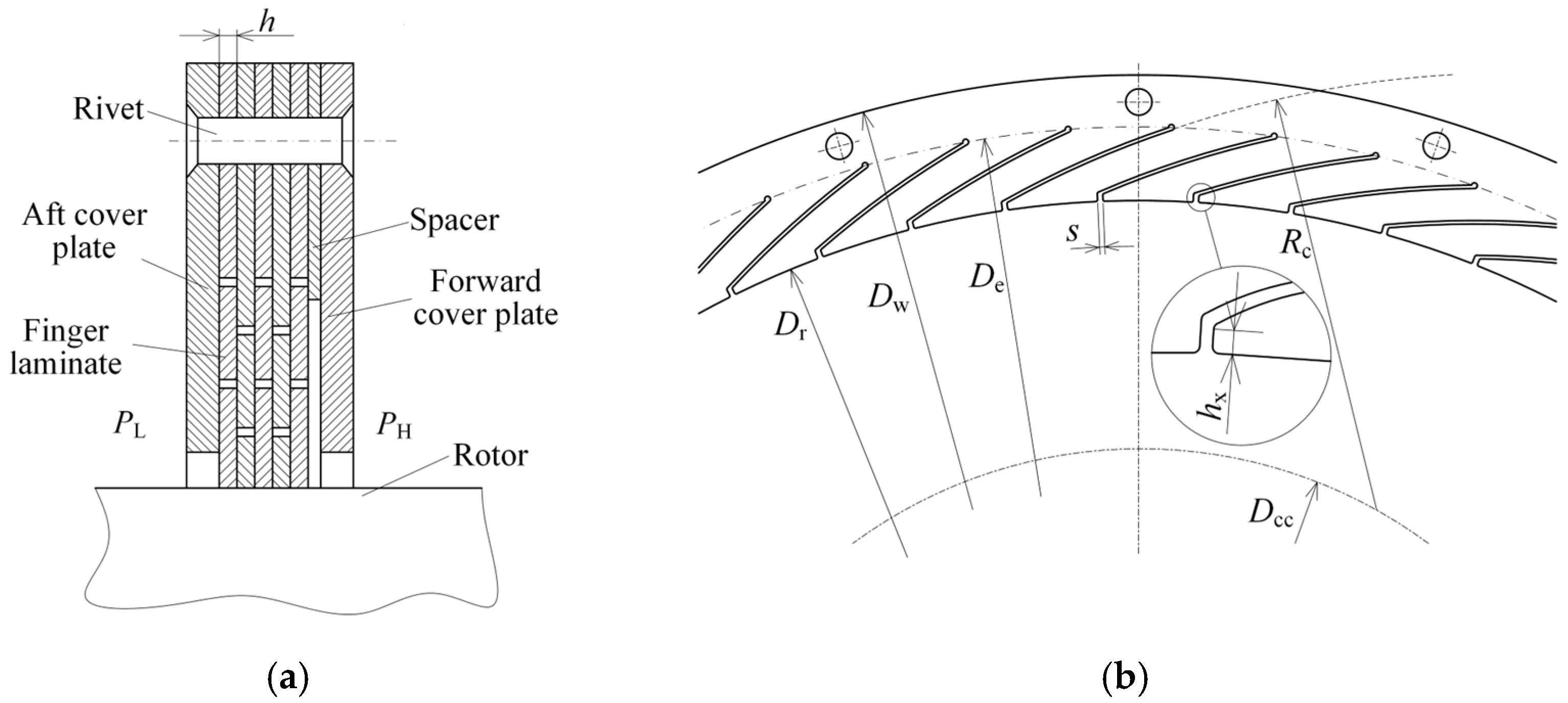
Figure 1. Finger seal geometric structure. (a) Axial view of finger seal system, (b) End view of one finger laminate.
Applmech 06 00080 g001
Figure 2. Force analysis and Equivalent dynamic model of the high-pressure finger in contact state. (a) Force analysis of the High-pressure finger, (b) Equivalent dynamic model of the high-pressure finger.
Applmech 06 00080 g002
Figure 3. Equivalent dynamic model of finger seal system based on distributed mass. (a) Contact state, (b) Non-contact state.
Applmech 06 00080 g003
Figure 4. Thermal-structural analysis model of finger seal systems.
Applmech 06 00080 g004
Figure 5. Temperature distribution (in °C) of the 3Y+2X finger seal configuration.
Applmech 06 00080 g005
Figure 6. Thermal deformation (in mm) of the 3Y+2X finger seal configuration.
Applmech 06 00080 g006
Figure 7. Dynamic displacement response of the 3Y+2X finger seal configuration.
Applmech 06 00080 g007
Figure 8. Dynamic leakage gap of different configurations.
Applmech 06 00080 g008
Figure 9. Dynamic leakage rate of different configurations.
Applmech 06 00080 g009
Figure 10. Rubbing force of different configurations.
Applmech 06 00080 g010
Figure 11. Dynamic leakage rate under different pressure differentials.
Applmech 06 00080 g011
Figure 12. Rubbing force under different pressure differentials.
Applmech 06 00080 g012
Figure 13. Comparison of leakage rate results under different pressure differentials with and without thermal effects.
Applmech 06 00080 g013
Figure 14. Comparison of rubbing force results under different pressure differentials with and without thermal effects.
Applmech 06 00080 g014
Figure 15. Dynamic leakage rate under different displacement excitations.
Applmech 06 00080 g015
Figure 16. Rubbing force under different displacement excitations.
Applmech 06 00080 g016
Figure 17. Comparison of leakage rate under different displacement excitations with and without thermal effects.
Applmech 06 00080 g017
Figure 18. Comparison of rubbing force under different displacement excitations with and without thermal effects.
Applmech 06 00080 g018
Figure 19. Dynamic leakage rate at different temperatures.
Applmech 06 00080 g019
Figure 20. Rubbing force at different temperatures.
Applmech 06 00080 g020
Figure 21. Comparison of theoretical and experimental results in high-temperature environment (T = 300 °C).
Applmech 06 00080 g021
Table 1. Structural parameters of Y-type and X-type finger seal.
ParametersSymbolValueUnits
Type YX
Arc profile radiusRc8990mm
Center circle diameterDcc2723mm
Root diameter of finger beamDe185180mm
Seal inner diameterDr165mm
Seal outer diameterDw210mm
Number of finger beamsnf48
Gap between beamss0.4mm
Thickness of finger elementh0.5mm
Number of finger elementsns5
Height of finger foothx2.23.2mm
Downstream protective clearancegd1.2mm
Table 2. Equivalent parameters of X/Y-type finger seals at room temperature.
TypeEquivalent Structural Stiffness Coefficient (N/m)Equivalent Mass (kg)Contact Stiffness Coefficient
Between Fingers and the Rotor (N/m)
X1587.701.70 × 10−434,427.09
Y618.991.61 × 10−413,422.07
Table 3. Equivalent structural stiffness coefficient of X/Y-type finger seals with thermal effects.
Temperature (°C)Kxt (N/m)Kyt (N/m)Kxj (N/m)Kyj (N/m)
1001628.82498.161826.91529.1
2001503.56484.991727.92516.42
3001382.97471.071624.88506.63
4001267.06456.391517.77499.71
Disclaimer/Publisher’s Note: The statements, opinions and data contained in all publications are solely those of the individual author(s) and contributor(s) and not of MDPI and/or the editor(s). MDPI and/or the editor(s) disclaim responsibility for any injury to people or property resulting from any ideas, methods, instructions or products referred to in the content.