Abstract
Conical screw compressors are equipment used to compress air or other gases, using a mechanism consisting of two conically shaped rotors (screws), which rotate one inside the other. This specific design offers advantages in terms of its efficiency, durability and compactness. These compressors are characterized by high efficiency, efficient compression, low air loss, durability, compact dimensions and silent operation. In conical screw compressors, the screw axes are arranged at an angle, due to the conical shape of the screws. This arrangement allows for the progressive compression of the gas as it advances along the screws. On the one hand, the arrangement of the axes and the conical shape of the screws contribute significantly to the high performance of this type of compressor, but on the other hand, this shape makes it difficult to profile these active elements. The screw profiles of conical screw compressors are mutually enveloping, and this aspect is essential for the correct operation of the compressor. In this paper, a new algorithm for profiling the compressor’s external rotor starting from a known internal rotor shape is proposed. The proposed algorithm was developed at “Dunarea de Jos” University of Galati and was based on the observation that the compression chambers in conical screw compressors are sealed according to a curve that follows the axial section of the two screws, in a plane determined by their axes. Practically, the two screws admit a common contour of the axial section in the plane determined by their axes. Taking this aspect into account, the transverse profile of the outer screw can be determined by identifying the positions where contact will take place with the points belonging to the transverse profile of the inner screw. In order to verify the viability of this method, the volume occupied by the inner screw during its relative movement with respect to the outer screw was determined. This volume was compared with the volume of the outer rotor cavity, with the result demonstrating the identity of the two volumes.
1. Introduction
Rotary screw compressors are an essential technology in many industrial applications, being widely used for gas compression, refrigeration, air blowing systems and vacuum pumps. The popularity of this equipment is due to their outstanding technical characteristics, such as high energy efficiency, operational reliability and low noise levels, which make them suitable for various industrial environments, even under particularly demanding conditions [1].
Broerman et al. [2] indicate that in general, two types of screw compressors can be identified: dry screw compressors and oil-flooded screw compressors. According to Broerman, the thermodynamic behavior of screw compressors is similar to that of piston compressors. The power consumption is almost independent of the molecular weight of the gas. The volumetric gas flow at the inlet does not change significantly when the compression ratio or the molecular weight of the gas varies.
Among the advantages of using screw compressors, Broerman identifies the following aspects: a screw compressor can operate with a wide variety of gases; a screw compressor can function at very high compression ratios (for oil-injected screw compressors, compression ratios of up to 25 can be achieved in a single stage, while for dry screw compressors, a compression ratio of up to 10 is possible with liquid injection); the compact rotor design, with a reduced number of lobes, provides robustness; the clearances between the rotors and the casing are in the order of fractions of a millimeter, which means that any accumulation of residue from the process gas is removed, and the balance of the rotors is not affected; unlike piston compressors, screw compressors do not have valves for controlling the intake and discharge of gas from the working chamber, and therefore valve failure is not an issue with screw compressors; and the tip speeds of the rotor profiles are lower than those of centrifugal or axial compressors.
Xudong et al. [3] state that as industries such as the food, pharmaceutical, electronics and chemical engineering industries move toward high-performance refinement, there is an increasing demand for pure, oil-free compressed gas. This demand is driven by the need to ensure product quality, meet precise technological requirements and strictly comply with production safety standards. They also examined other relevant technologies that could contribute to the development of more efficient compressors.
Kumar et al. [4] point out that screw compressors are essential components in various industrial sectors, such as manufacturing, energy and construction, accounting for approximately 10–20% of industrial electricity consumption. Despite their widespread application, the energy demand of multistage screw compressors contributes significantly to carbon emissions. They anticipate that the global screw compressor market will grow at a compound annual growth rate (CAGR) of 6.5%, reaching a market value of USD 19.37 billion by 2030. This highlights the increasing demand for more energy-efficient compressor systems.
In this context, researchers such as Hu et al. [1] have developed advanced strategies for energy saving and performance improvements. These strategies may include optimizing the rotor profile, implementing intelligent control systems, using advanced materials to reduce the mechanical and thermal losses and integrating with renewable energy sources.
Structural optimization of compressors is also a focus for the research team led by Ma et al. [5], who conducted a study to investigate the performance of high-speed miniaturized screw refrigeration compressors. They used rotors with identical theoretical displacement but varying nominal speeds. Thermodynamic modeling was employed to assess the impact of different clearances and nominal speeds on the performance. Their study showed that while casing tip leakage represents the largest volumetric leakage in screw compressors, interlobe leakage contributes most significantly to power losses. When the nominal speed increases from 3000 rpm to 15,000 rpm, interlobe leakage remains the dominant source of power loss, with its relative contribution showing a significant increase. The same study also examines the influence of the wrap angle on volumetric efficiency.
Simulation of operations and structural optimization in the field of compressors are a current focus of research. Thus, Li et al. [6] state that twin-screw compressors have significant practical value in the fields of energy, refrigeration, construction, transportation and related industries. Due to the benefits of short development cycles and low costs, numerical simulation technology has attracted increasing attention. In recent years, numerical simulation technology for twin-screw compressors has advanced rapidly, yielding many important results. Against the backdrop of global energy conservation and carbon emission reductions, the simulation technique proposed by this research team enables a deeper understanding of the technical challenges, research hotspots and development trends in related fields.
Xudong et al. [7] observed that high-temperature heat pump systems with compression for steam production (HTHPSSs) have a higher energy efficiency than electric, coal-fired or gas-fired boilers used for steam generation. These systems effectively recover waste heat from the plant, and the CO2 emissions can be reduced depending on the electricity model used for the power supply, which is consistent with a development strategy oriented towards energy saving, environmental protection and achieving climate neutrality.
The key element in HTHP research is the development of high-temperature refrigerants and compressors capable of operating at a high compression ratio.
An increasingly current concern is the analysis of the research status in the field of high-temperature and high-pressure compressors, with an emphasis on their design and strategies for reducing the discharge temperature for various types of compressors. Research is aiming to develop compressors capable of achieving a high compression ratio.
Franconi et al. [8] demonstrate that the reversible use of a volumetric machine as both a compressor and an expander shows potential for micro-scale compressed air energy storage systems due to the lower investment costs and greater operational flexibility. Their research team experimentally investigated the reversible use of an oil-injected twin-screw compressor as an expander for a compressed-air energy storage system. The results indicated that the compressor exhibited good efficiency and required a low input power. Calculations showed that this machine could operate within such an energy storage system and could deliver up to 90% of the energy recovered during the charging process when the stored air temperature was 80 °C.
Săvescu et al. [9] conducted experimental work on a twin-screw compressor to validate and demonstrate piezoelectric energy harvesting.
Chuang et al. [10] believe that large-scale cryogenic refrigeration equipment is the only way to create the cryogenic environment required in scientific facilities for purposes such as space technology, quantum computers and magnetic levitation. As one of the essential moving components of a cryogenic system, the helium compressor determines the reliability and performance of the entire system.
These researchers have relied on the fact that the twin-screw helical compressor type is a promising option for use in large-scale cryogenic refrigeration systems due to its high efficiency and reliability. It can also be used in the helium refrigeration cycle to produce liquid hydrogen, which is required for hydrogen fuel cells, which have attracted increasing interest in recent years.
Chuang Wang et al. developed a high-efficiency oil-injected twin-screw helical compressor for helium. To achieve superior efficiency and reliability, several methods were adopted to overcome difficult problems related to losses (leakage) and significant temperature increases. The rotor profile was specifically designed for this application.
The results demonstrated that this twin-screw helical compressor with helium oil injection exhibited an excellent performance.
Dantong et al. [11] focused on an Intersecting-Axis Internally Geared Screw Compressor (IISC). This is an emerging advanced positive displacement machine that has the potential to significantly expand the scope of screw compressor technology. The core component of the IISC is a pair of internally geared rotors with intersecting-axis gearing, but its design methodology is a current concern of specialists in the field. They developed a geometric model of the rotor pair and analyzed the influence of the main parameters on the geometric performance. First, a generation model for the rotor pair was presented, with all of the corresponding parameter sets defined. The proposed model was validated by manufacturing a pair of rotors using 3D printing and CNC machining techniques.
Subsequently, a geometric analysis model for the IISC was established which included the working volume and leakage channels, and it was verified using a commercial 3D software. Using this analysis model, the parameters of the rotor pair (rotor profile, cone angle, wrap angle and L/D ratio) were studied to develop a design methodology for IISC compressors.
At the end of Dantong Li’s work, the variable-pitch technology was addressed, proposing a new method of variable pitch control, aiming to improve the performance of IISC compressors further.
Qingxiang et al. [12] focused on the calculation principle for the limiting line of engagement in the case of conical surface meshing. Equations for the tooth surface, the meshing function and the limiting meshing function of a pair of conical worms were derived. Investigation of the limiting line of engagement involves solving an equivalent single-variable nonlinear equation, which is obtained from the original four-variable equations using an elimination technique.
Conical screw compressors emerged as a natural evolution of conventional screw compressors in the context of the requirements for the energy efficiency, small size and low vibration of the equipment. The first theoretical concepts regarding the use of conical screw rotors were developed at the end of the 20th century, motivated by the desire to obtain higher compression ratios and a significant reduction in internal leakage losses. Early work focused on studying the gearing of rotors with non-parallel axes and on the mathematical modeling of conical screw profiles, as highlighted by the research carried out by Fujiwara [13] and later continued by Lu [14], who deepened the analysis of the volumetric efficiency of these compressors over a wide range of pressure ratios.
The literature highlights the contributions of Hu et al. [1], who developed a complex mathematical model for generating conical rotor surfaces, as well as Olly Dmitriev and his team at VERT Rotors [15,16], who have realized practical applications of conical compressors in niche areas such as microsystems, robotics and nanosatellites. Their experimental studies have validated the theoretical hypotheses, demonstrating the functional and structural advantages of a conical geometry in real applications.
Conical screw compressors are an innovative evolution of conventional screw compressors, using a conical geometry to achieve significant functional and structural advantages. Their particular geometry allows for a reduction in the internal leakage losses; improved suction and discharge processes; and optimized gearing profiles between the rotors.
A recent example of the application of this technology, described by Dmitriev et al. [16], is the microcompressor developed by VERT Rotors. VERT Rotors has designed an ultra-low-vibration rotary compressor using conical screw rotors with a length of 40 mm, achieving a compression ratio of 1:10. This compressor consists of a conical inner rotor, which rotates inside an outer rotor. The configuration allows for efficient engagement and vibration reduction, while ensuring the increased compactness of the assembly and the possibility of integration into applications where space and mass are major restrictions.
Thus, conical screw compressors open new directions of research and application, offering viable solutions for systems where vibrations, a small size and energy efficiency are critical factors.
Zhao et al. [17] conducted a study investigating the effect of mechanical preloading on the performance of a gas foil conical bearing (GFCB), using numerical methods such as the finite difference method (FDM) and the finite element method (FEM). Both the static and dynamic behavior of the bearing under various preload conditions were analyzed, taking into account the influence of the gas film temperature. A practical test on an air compressor for fuel cell vehicles confirmed the theoretical results. The conclusions show that preloading significantly improves the load capacity, friction torque, rotor stiffness and stability while reducing the shaft trajectory and delaying the onset of low-frequency vibrations.
In another paper, Dmitriev et al. [16] present experimental data and evaluate the ability of conical screw compressors to become a preferable alternative to other designs in small applications. The results demonstrate that this type of compressor represents an attractive alternative for small, oil-free applications.
On the other hand, conical screw and intersecting shaft compressors have shown great potential to improve the performance of hydraulic and pneumatic equipment. To investigate the generation method, Wangfeng et al. [1] established a mathematical model for generating the conical rotor surface by decomposing it into the rotor profile on the sphere and the conical helix. A meshing model between two rotors with intersecting shafts was presented based on the separate solution for the conjugate rotor profiles on the sphere. Subsequently, several common rotor curves in screw equipment were extended to the sphere by analogy, and equations for their mathematical generation were presented. The results showed that the proposed method can efficiently generate several conical twin-screw and intersecting shaft rotors for typical applications. The results obtained showed that a conical rotor has the potential to improve the suction and exhaust process, while reducing the losses and force in the exhaust area.
Lu [14] conducted a study demonstrating that this type of compressor can maintain a high level of volumetric efficiency over a wide range of pressure ratios. The results demonstrate that improving the compressor design can ensure that the temperature increase is limited, reducing the relative speed and increasing the overall efficiency of the machine.
Baroiu et al. [18] demonstrated that it is possible to build a screw with circular lobes which meets the requirements of active screws for conical compressors. The construction of screws with a profile formed of arcs of a circle may represent a simpler solution than the current solution. Screws with circular profiles are, in principle, more advantageous solutions from a technological point of view. At the same time, the measurement possibilities are more rigorous, and the generation tools are easier to make.
Vasie et al. [19] focus on the process of generating non-circular gears, namely variable-speed gears. To generalize the generation process, the Gielis curve is proposed as the centrode. The authors created original algorithms to configure the main stages of the variable-speed gear generation process that can also serve for analyses of the mutually winding profiles of screw compressors.
Crăciun et al. [20] used the virtual contact point method to profile disc-type tools intended for generating cylindrical helical surfaces with a constant lead. Building on this method, we extended its applicability to studying conical helical surfaces with a constant lead, with direct applications to profiling the rotors of conical screw compressors. As a future research direction, we aim to verify the applicability of the “virtual contact point” method to the study of conical helical surfaces with a variable lead.
2. Materials and Methods
Contact between two mutually enveloping surfaces, Σ and S, occurs along a curve called the characteristic curve.
At a given moment, each point of the surface Σ reaches the characteristic curve and thus also belongs to surface S.
Therefore, the entirety of the points belonging to the surface Σ can be imagined as representing “virtual contact points” with the surface S. The actual contact points between the two surfaces at any moment define the “characteristic curve”. Determining the characteristic curve involves establishing an enveloping condition.
In the case of conical helical screw compressors, the lateral surfaces of these screws are mutually enveloping surfaces.
Thus, considering a current point on the surface of one rotor, for example, the inner rotor, and applying to it the movement executed by the rotor, it is possible to identify the moment when this point reaches the characteristic curve. At that moment, when the point lies on the characteristic curve, it will be in contact with a point belonging to the conjugate rotor surface, i.e., the outer rotor. The contact position can be determined in a fixed reference system independent of the two rotors. Subsequently, by applying an inverse movement to the second point, its initial position can be determined, i.e., its position in a reference system fixed to the outer rotor.
In the proposed method, the enveloping condition is that the point lies in the contact plane, the plane determined by the axes of the two rotors. This method benefits from the advantage of being relatively simple to apply and avoids the need for extensive calculations while remaining analytically exact.
The disadvantage of this method is that the shape of the contact curve must be known beforehand. However, in the case of conical helical compressors, this is possible since the meshing curve represents the intersection curve of the conical helical surface of each rotor with the contact plane. The contact plane is the plane defined by the axes of the two rotors.
To profile one of the active elements of the helical compressor, we start from the numerical model of the conjugate element and from the observation that the two active elements are sealed through their contact in a plane determined by their axes of rotation. The two active elements are the inner and outer conical screws.
The conical helical lines passing through points on the transverse profile of one of the active elements are determined, and the coordinates of the intersection points between these helical lines and the sealing plane are determined.
Subsequently, the coordinates of the intersection points are expressed from the reference system joined to that active element in the reference system associated with the conjugate active element.
To determine the cross-sectional profile of the conjugated active element, the equations for a new set of helical lines are determined, this time located on the conical helical surface of this element, and the coordinates of the intersection points between the helical lines belonging to the set and the X1OY1 plane belonging to the reference system of the active element are determined.
Verification of the results was carried out by modeling the cavity belonging to the outer rotor (the conjugated active element) and comparing the model with the winding of the successive positions occupied by the inner rotor during its movement.
The modeling was carried out in the CATIA V5R21 program. The results obtained were in the form of “.stl” and “.stp” files.
Comparison of the files was carried out in the GOM Inspect 2019 program.
3. Inner Rotor Modeling
3.1. Equations of the Inner Rotor’s Cross-Section
We start from the cycloidal profile of the inner rotor, assuming that this profile is composed of two arcs, respectively , representing a hypercycloid and the arc , representing a hypocycloid. The radii of the roulettes for the two cycloids are chosen to be equal to each other.
The active elements of the conical helical compressor have a different number of lobes. If the inner rotor has Z lobes, the outer rotor will have Z + 1 lobes. Each of the lobes corresponds to an arc of a angle on the base circle. If we assume that the radius of the base circle is R1, we can calculate the value of the roulette radius, r, necessary for it to generate an integer number of lobes when it travels the entire length of the base circle.
The resulting equation is
Figure 1 shows the reference systems used to generate the two centrodes.
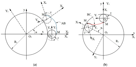
Figure 1.
Reference systems used to generate lobes: (a) external; (b) internal.
The following reference systems are used:
- -
- The x1y1 reference system integral with the inner rotor, having its origin in the center of the base circle of the cycloid. This base circle coincides with the rolling circle of the inner rotor. We note that the rolling between the two conjugate centrodes, associated with the conical worm profiles, is identical in planes perpendicular to the rotation axis of each worm, but the rolling radius changes in value depending on the position of the respective plane along the worm axis. In the following, the plane corresponding to the elevation z1 = 0 will be called the base plane of the inner rotor.
- -
- X1Y1—the mobile reference system, with the position of the X1 axis determined by the direction of the segment; see also Figure 1.
- -
- XeYe—the mobile reference system, solid with a roulette that generates the outer lobe.
- -
- XiYi—the mobile reference system, solid with a roulette that generates the inner lobe.
In Figure 1, the XeYe and XiYi systems were represented using a continuous line in the initial position and with a broken line in an intermediate position during the run.
Between the X1Y1 and XeYe systems, the rotational movements characterized by the transmission ratio are established:
In Equation (1), u represents the rotation angle of the X1Y1 system relative to the fixed xy system, and v is the rotation angle of the XeYe system relative to the X1Y1 system.
In the rotational movement of this system, its coordinates will be given by the equations
Taking into account the fact that the XeYe system has rotational movement relative to the X1Y1 system around the Z1 axis and at the same time rotates around its own Ze axis, its coordinates in the x1y1 system will be determined by the movement
where
Taking into account Equations (1), (3) and (4), the equations of the arc become (see Figure 1)
u having values in the range .
For the inner lobe, represented by the hypocycloid arc , the procedure is similar, but this time, the current point will have the coordinates
and in the rotational movement of the XiYi system its coordinates will be given by the equations:
The XiYi system also has rotational movement relative to the X1Y1 system but in the opposite direction to that of the XeYe system; therefore, its movement relative to the fixed xy system will have the form
where
Taking into account Equations (1), (8) and (9), the equations of the arc become (see also Figure 1)
u having values in the range .
The shapes of the lobes obtained using Equations (6) and (11) are shown in Figure 2.
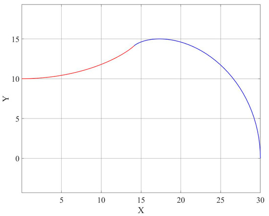
Figure 2.
The cycloid arcs (blue) and (red).
3.2. Determination of Helical Lines
Each of the points in the cycloidal profile will generate a conical helical line of a constant pitch. If it is assumed that in the X1Y1 plane, the current point has the coordinates determined by Equations (6) or (11), as the case may be, the polar radius of this point is
The polar radius in a plane at a distance h from the X1Y1 plane will be
where α1 is the semi-angle at the apex of the cone. The value of α1 can be calculated using the relation
being the semi-angle at the apex of the conical surface corresponding to the base circle.
For a polar angle φ1 that defines the rotation of the current point M on the helical line relative to the x1 axis of the system and a position angle u that establishes the position of the current point on the cycloidal profile in the base plane, the coordinates of this point will be (see Figure 3)
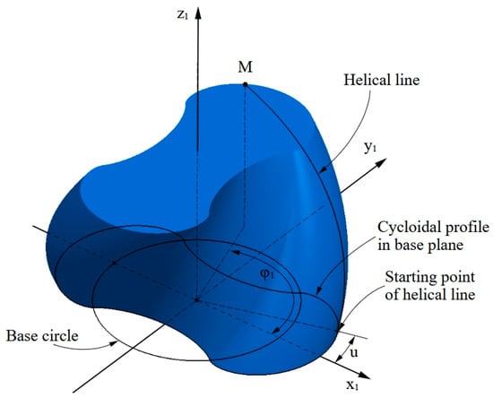
Figure 3.
Position of current point M.
In Equation (15), are given by Equations (6) or (11), as the point belongs to the or arc.
In Figure 4, the conical helical lines passing through several points on the transverse profile of the inner rotor are represented.
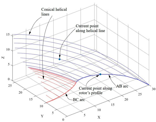
Figure 4.
Conical helical lines drawn through points belonging to the cross-sectional profile.
4. Determining the Enwrapping Condition
The establishment of the winding condition is based on the observation that the sealing between the screws of the conical helical compressor is due to their contact in a plane determined by the two axes of rotation.
Therefore, the points that will be in contact must reach this plane simultaneously during the rotational movement of each of the screws.
Based on this observation, we can determine the polar angle φ1 by which the internal screw must be rotated so that a current point on the helical line reaches the contact plane.
If in Equation (15), the condition is set, it can be obtained:
The enwrapping condition can therefore be written in the form
for the arc and, respectively,
for the arc.
5. The Mathematical Model of the Meshing Surface of the Outer Rotor
5.1. Determining the Outer Rotor’s Profile in the Base Plane
Figure 5 shows the reference systems associated with the two rotors and the fixed reference system, xoyozo, which connects the other two. As stated in Section 3, the reference system associated with the inner rotor is the x1y1z1 system. The solid system of the outer rotor is the x2y2z2 system.
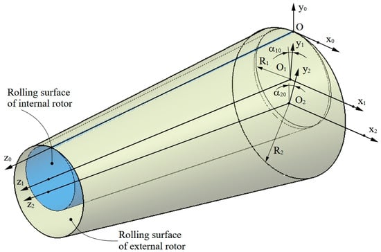
Figure 5.
The rotor-associated reference systems and the link reference system.
The contact point corresponding to a certain rotation φ1 of the inner rotor will have, in the reference system of the outer worm, the coordinates given by the coordinate transformations:
resulting in
If we denote by the coordinates of a point on a helical line, a point that complies with the winding condition, i.e., it is in the sealing plane, to identify the corresponding point on the outer worm profile, the corresponding helical line is drawn, which will be traversed in the opposite direction, with the angle φ2 given by the rolling condition
In this way, the coordinates of the points on the outer worm profile are obtained:
In Equation (23),
and is given by
In this way, the transverse profile of the outer rotor is obtained, in the plane X2Y2.
5.2. Modeling the Meshing Surface of the Outer Rotor
The numerical model of the gap in the outer rotor is given by the equations of the helical lines described by the points belonging to the profile of this rotor in the plane :
In relations (26), pe2 is the helical parameter of the outer rotor. The value of this parameter is calculated using the relation
6. Checking the Results
The correctness of the results obtained can be verified by modeling the trace left by the inner rotor during its relative movement with respect to the outer rotor.
For this purpose, we modeled the inner rotor in CATIA version V5R21, based on the virtual contact point method.
The modeling was undertaken by importing into CATIA the coordinates calculated using Equation (26). As shown in Section 5.2, these points belong to the profile of the outer rotor, in the plane . Next, a spline curve was drawn through these points, materializing the rotor profile in that plane. It should be noted that since the rotor has axial symmetry, it is not necessary for the calculated points to be distributed along the entire length of the profile but only over half a lobe. Subsequently, by using the symmetry and rotation commands available in CATIA, the complete rotor profile can be obtained as a closed spline curve.
The next step consisted of generating a helix corresponding to one of the helical lines on the surface of the outer rotor and lying on the running surface of this rotor. The helix pitch is given by relation (27).
Using CATIA’s capabilities, the lateral surface of the rotor was generated using the SWEEP command, with the option of generating it using two guide curves. The first of these curves is the rotor axis, and the second is the generated helical line.
In this way, the numerical model of the outer rotor’s clearance was obtained. It should be noted that although for the physical rotor the surface obtained is an inner surface (with the surface mutually enveloping the helical surface of the inner rotor), for the special purpose of verifying the correctness of the method, the numerical model is obtained as an outer surface.
In the next stage, to compare the two surfaces, the numerical model obtained will be called the CAD model, being the equivalent of the 3D numerical model obtained by design.
Independently of this model, an assembly consisting of three distinct elements was created. The first element is a geometric structure that materializes the positions of the axes of the two rotors within the compressor. This element is considered fixed and serves as the base element of the assembly.
The second element consists of the numerical model of the inner rotor, obtained based on the input data, and whose lateral surface is described by Equation (14). Additionally, this element contains the materialization of the inner rotor’s axis.
The third element is the one containing the materialization of the outer rotor’s axis.
Using CATIA’s mechanism simulation capabilities, a numerical model of the inner rotor was rotated, respecting its relative movement to the outer rotor, specifically rotation about its own axis by the angle and simultaneously rotation about the outer rotor’s axis by the angle . The relation between the two angles is given by Equation (22).
The model intended for verification was obtained as the envelope of the successive positions occupied by the inner rotor during its relative movement with respect to the outer rotor. It should be noted that the possibility of obtaining this envelope of the positions occupied by a solid during a known movement is also a feature of CATIA.
Next, for verification using the GOM Inspect software, version 2019, this second numerical model was considered equivalent to a model obtained by scanning a real physical part.
GOM Inspect is a computer-aided inspection software that allows a numerical model obtained using video scanning equipment to be imported and this model to be measured. One of the software’s capabilities is to compare the scanned model with a CAD 3D model and to display the deviations in the physical model from the CAD model.
It is represented as a deviation map, where the magnitude of the deviations is color-coded. On this map, positive deviations are shown in red and negative deviations in blue. The greater the deviation value, the darker the color. Areas where the deviations are below certain user-defined limits are shown in green.
Figure 5 shows the inspection result. For the inspection operation, the CAD model obtained from analytical calculations was considered the reference element, and the model obtained as the envelope of successive positions of the inner rotor was considered equivalent to the scanned model.
On the deviation map, the user can also display the magnitude of the deviations at various points of interest.
Figure 5 shows some of these deviations in areas with the maximum values. The numerical values are given in millimeters. On the right-hand side of the figure, a legend of the deviations is presented, showing the values corresponding to different colors.
Considering the fact that the two outer surfaces of the rotors are mutually enveloping surfaces, it is expected that this trace will coincide with the gap in the outer rotor, that is, the inner rotor will fill the existing gap in the outer rotor through its successive positions.
The comparison of the two models, made in the GOM Inspect program, version 2019, demonstrates the good overlap between them. The values of the deviations at several points, where the differences between the surfaces have higher values, are shown in Figure 6.
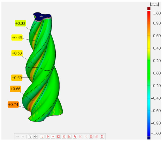
Figure 6.
Result of comparison between CAD model and trace left during movement.
It should be noted that these deviations are not caused by calculation errors but by the fact that the graphical representations are subject to limitations caused by the positioning of the rotor with a finite number of steps during the movement. For the surface of the real object, it is characterized by a continuous surface, which will lead to much smaller deviations.
To verify the clearance between the two rotors, the distance between the conjugate helical surfaces was analyzed in their operating position.
The analysis was performed in CATIA using the Band Analysis command and allowed the areas where the distance between the surfaces ranged from 0 to 0.3 mm to be highlighted. Typically, in screw compressors, this clearance is in the order of fractions of a millimeter [2], which is within the range used for the analysis.
Figure 7 shows the result of this analysis. It is clearly visible that the green areas, where the distance falls within the specified limits of 0–0.3 mm, are located on the outside of the inner rotor’s profile and follow the helical line of this rotor. This demonstrates the ability of the two rotors to ensure the sealing necessary for proper operation.
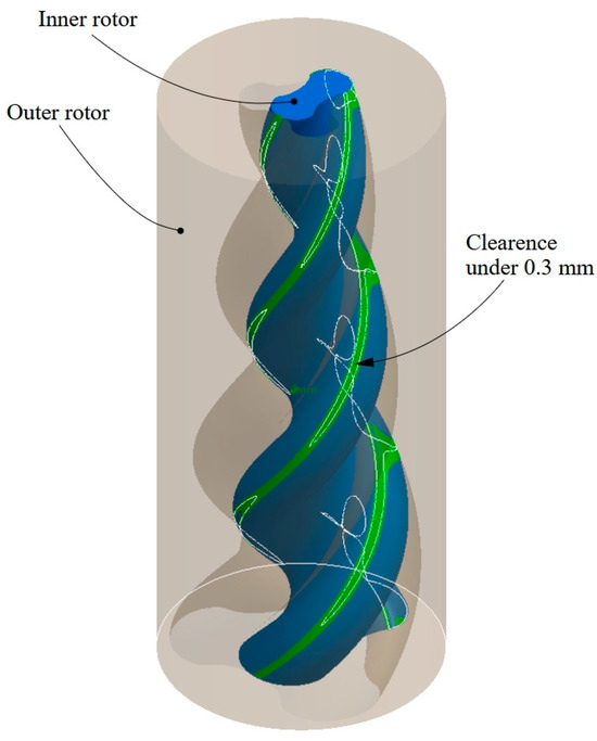
Figure 7.
The band analysis of the clearance between the two helical surfaces.
Figure 8 shows the distance between the conjugate helical surfaces near the contact plane. As explained in Section 2, the contact plane is defined by the axes of the two rotors and is used to identify the meshing condition.
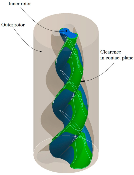
Figure 8.
Band analysis between surfaces in contact plane.
7. Discussions and Conclusions
The proposed profiling algorithm allows the profile of one of the rotors in a conical compressor to be determined, starting from the known profile of the conjugate rotor.
Profiling involves the use of relatively simple mathematical relationships, which do not require a large volume of calculations or high-complexity calculations.
The algorithm can be used for any configuration of conical screw compressors and can also be extended to other types of compressors that operate on the principle of surface wrapping.
The proposed profiling algorithm can also be extended to variable-pitch screw compressors, as well as to any type of mutually enveloping surfaces where the shape of the contact line is known. The algorithm is applicable to all types of helical surfaces, regardless of the apex angle of the generating helix cone, the pitch, or the number of starts, provided that the two surfaces are in contact along a curve that can be identified.
In the case of conical helical compressors, this curve is represented by the intersection of the rotor’s helical surface with a plane defined by the axes of the two rotors. Considering that the shape of one of the rotors is known, the shape of the conjugate rotor can be determined using the meshing condition that the helical lines intersect with the contact plane.
The verification performed by comparing the gap in the outer rotor with the space successively occupied during the movement of the inner rotor is suggestive but requires the use of specialized software that allows the relative movements between the components of a mechanism to be simulated and, respectively, the numerical comparison of two virtual models.
The results of verifications performed in this way are affected by the limitations regarding the possibility of performing simulations.
It is possible that there are areas on the elements subject to verification that are difficult to analyze. In the case analyzed in this paper, the frontal areas of the numerical models do not overlap exactly (see Figure 6) due to the way in which they were obtained.
For the reference model, which is the outer rotor’s cavity, these areas are flat surfaces. For the model obtained by simulating the movement, the respective areas are conical surfaces because the axes of the two rotors are not parallel.
However, we do not consider these errors to affect the quality of the verification since the areas of interest are the lateral surfaces of the rotors, which represent the working surfaces. The frontal surfaces do not have a functional role in the models obtained for verification and therefore do not influence the results of the analysis.
The analysis of the distance between the conjugate surfaces demonstrates that in the areas near the contact plane and on the outer profile of the inner rotor, the clearance between the surfaces falls within the required limits for the operation of this type of compressor.
Author Contributions
Conceptualization: V.G.T. and N.B.; methodology: V.G.T. and R.S.C.; software: V.G.T. and R.S.C.; validation: V.G.T. and G.A.M.; formal analysis: V.G.T. and N.B.; investigation: R.S.C. and V.V.T.; resources: R.S.C. and V.V.T.; data curation: R.S.C. and G.A.M.; writing—original draft preparation: R.S.C.; writing—review and editing: V.G.T. and G.A.M.; visualization: N.B.; supervision: V.G.T.; project administration: V.G.T.; funding acquisition: V.G.T. All authors have read and agreed to the published version of the manuscript.
Funding
This research received no external funding.
Institutional Review Board Statement
Not applicable.
Informed Consent Statement
Not applicable.
Data Availability Statement
The data are contained within the article.
Acknowledgments
The verifications were made in frame of the Research Center in Manufacturing Engineering Technology (ITCM), “Dunărea de Jos” University of Galati.
Conflicts of Interest
The authors declare no conflict of interest.
References
- Hu, W.; He, Z.; Li, D.; Kai, M.; Ziwen, X. Geometry of intersecting-axis conical twin-screw rotors. Mech. Mach. Theory 2022, 174, 104913. [Google Scholar] [CrossRef]
- Broerman, E.; Manthley, T.; Wennermar, H. Screw compressors. In Compression Machinery for Oil and Gas; Klaus, B., Rainer, K., Eds.; Elsevier: Amsterdam, The Netherlands, 2019; pp. 253–307. [Google Scholar]
- Ma, X.; Du, Y.; Li, B.; Wu, Y.; Zhang, C.; Zhu, T. A comprehensive review of key technologies for the development of oil-free single screw compressors. Appl. Therm. Eng. 2025, 269, 126003. [Google Scholar] [CrossRef]
- Kumar, A.; Kovacevic, A.; Stosic, N. Lifecycle cost analysis and performance evaluation of multi-stage screw compressors. Proc. Inst. Mech. Eng. Part C J. Mech. Eng. Sci. 2025, 239, 3144–3154. [Google Scholar] [CrossRef]
- Ma, K.; Wu, X.; Liu, H.; Li, D.; He, Z. Theoretical and numerical research on high-speed small refrigeration twin-screw compressor. Appl. Sci. 2025, 15, 3742. [Google Scholar] [CrossRef]
- Li, Y.; Zhao, X.; Liu, S.; Wang, C.; Shen, S. Review and prospects of numerical simulation research on internal flow and performance optimization of twin-screw compressors. Energies 2025, 18, 2608. [Google Scholar] [CrossRef]
- Ma, X.; Du, Y.; Zhao, T.; Zhu, T.; Lei, B.; Wu, Y. A comprehensive review of compression high-temperature heat pump steam system: Status and trend. Int. J. Refrig. 2024, 164, 218–242. [Google Scholar] [CrossRef]
- Francesconi, M.; Baldinelli, A.; Sani, L.; Antonelli, M. Experimental characterization of reversible oil-flooded twin-screw compressor/dry expander for a micro-scale compressed air storage system. Energies 2025, 18, 320. [Google Scholar] [CrossRef]
- Săvescu, C.; Comeagă, D.; Roman, M.; Lale, D.; Stoica, R.; Vasile, E.; Nechifor, C.; Stoicescu, A. Experimental study of a piezoelectric harvester vibrating on an industrial screw compressor. Rev. Roum. Sci. Tech. Électrotech. Énerg. 2025, 70, 9–14. [Google Scholar] [CrossRef]
- Wang, C.; Xing, Z.; Sun, S.; Yu, Z. Development and experimental study of a high-efficiency helium twin-screw compressor. Cryogenics 2021, 116, 103286. [Google Scholar] [CrossRef]
- Li, D.; He, Z.; Chen, X.; Sun, C.; Ma, K.; Wang, C.; Xing, Z. Meshing pair geometry of the intersecting-axis internally geared screw compressor. Int. J. Refrig. 2025, 169, 166–183. [Google Scholar] [CrossRef]
- Meng, Q.; Zhao, Y.; Yang, Z. Meshing limit line of the conical surface enveloping conical worm pair. Proc. Inst. Mech. Eng. Part C J. Mech. Eng. Sci. 2019, 234, 693–703. [Google Scholar] [CrossRef]
- Fujiwara, M.; Kasuya, K.; Matsunaga, T.; Watanabe, M. Computer modeling for performance analysis of rotary screw compressor. In Proceedings of the International Compressor Engineering Conference, West Lafayette, IN, USA, 11–13 July 1984. [Google Scholar]
- Lu, Y.; Hoang, K.; Noake, D.; Low, N. Design and analysis of conical rotary compressor. IOP Conf. Ser. Mater. Sci. Eng. 2022, 1267, 012001. [Google Scholar] [CrossRef]
- Dmitriev, O.; Tabota, E.; Arbon, I. A miniature rotary compressor with a 1:10 compression ratio. IOP Conf. Ser. Mater. Sci. Eng. 2015, 90, 012055. [Google Scholar]
- Dmitriev, O.; Arbon, I. Comparison of energy-efficiency and size of portable oil-free screw and scroll compressors. IOP Conf. Ser. Mater. Sci. Eng. 2017, 232, 012057. [Google Scholar] [CrossRef]
- Zhao, L.; Hu, H.; Wu, H.; Wang, J.; Zhao, J. Effect of preloaded gas foil conical bearing on the rotor dynamic performance of fuel cell air compressor. Proc. Inst. Mech. Eng. Part D J. Automob. Eng. 2025. [Google Scholar] [CrossRef]
- Baroiu, N.; Costin, G.A.; Teodor, V.G.; Oancea, N. Algorithm for screws profiling of a conical trilobed compressor—Analytical solution. IOP Conf. Ser. Mater. Sci. Eng. 2020, 968, 012030. [Google Scholar] [CrossRef]
- Vasie, M.; Mundo, D.; Andrei, L. New algorithm for variable speed gear generation process. In Power Transmissions, Proceedings of the 4th International Conference, Sinaia, Romania, 20–23 June 2012; Springer: Dordrecht, The Netherlands, 2013; Volume 13, pp. 435–444. [Google Scholar]
- Crăciun, R.S.; Baroiu, N.; Oancea, N.; Teodor, V.G. Virtual contact point method. Side mill generating a cylindrical helical surface. Int. J. Mod. Manuf. Technol. 2024, 17, 130–136. [Google Scholar] [CrossRef]
Disclaimer/Publisher’s Note: The statements, opinions and data contained in all publications are solely those of the individual author(s) and contributor(s) and not of MDPI and/or the editor(s). MDPI and/or the editor(s) disclaim responsibility for any injury to people or property resulting from any ideas, methods, instructions or products referred to in the content. |
© 2025 by the authors. Licensee MDPI, Basel, Switzerland. This article is an open access article distributed under the terms and conditions of the Creative Commons Attribution (CC BY) license (https://creativecommons.org/licenses/by/4.0/).