Experimental and Numerical Analysis of Corrosion-Induced Cracking in Reinforced Concrete


Abstract
1. Introduction
2. Methodology
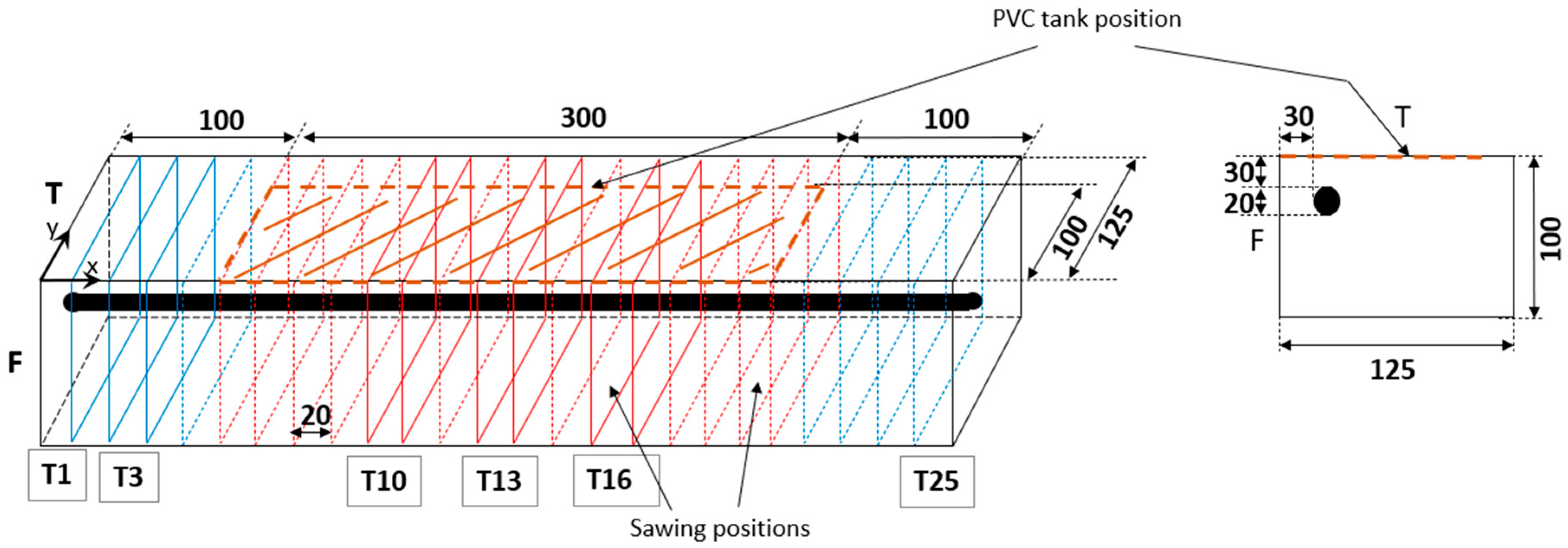
2.1. Experimental Programme
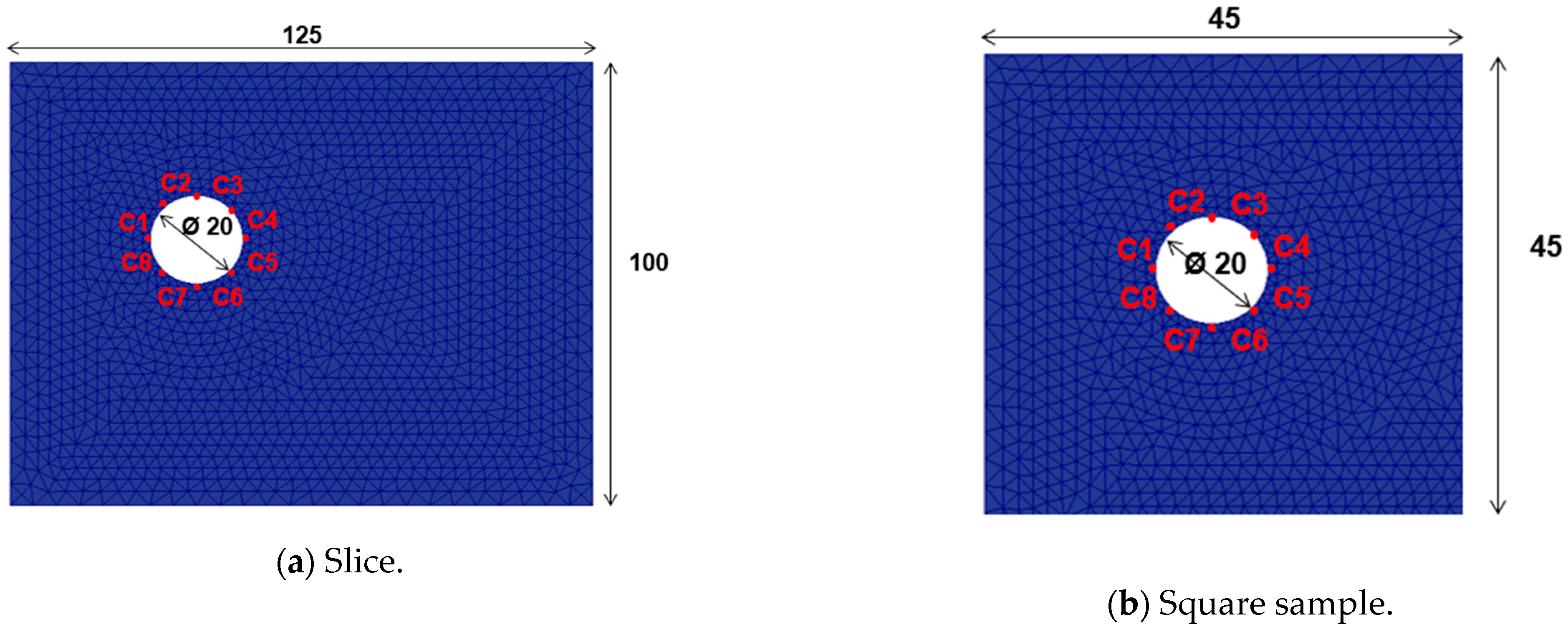
2.2. Numerical Model
3. Results
3.1. Experimental Results
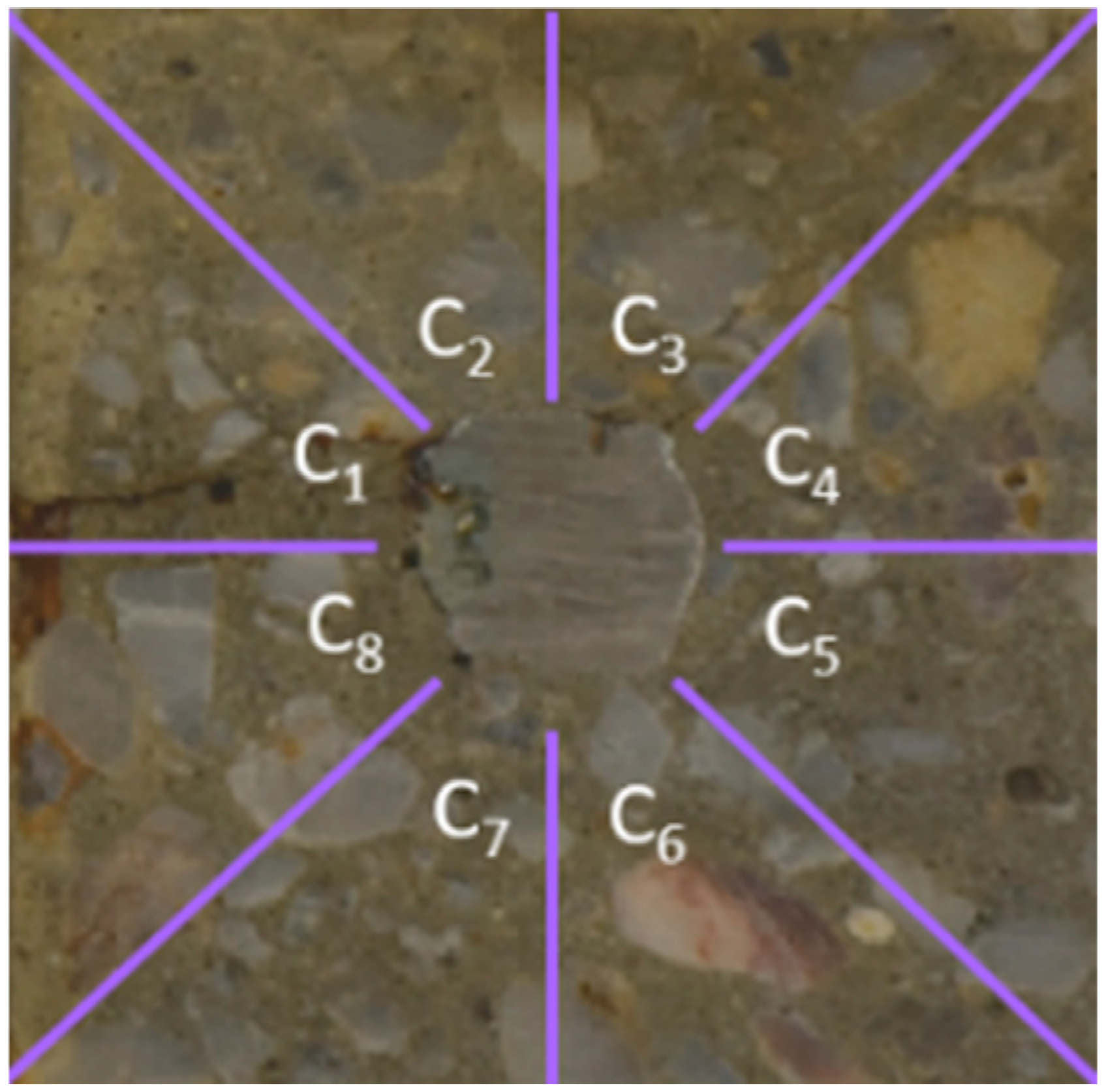
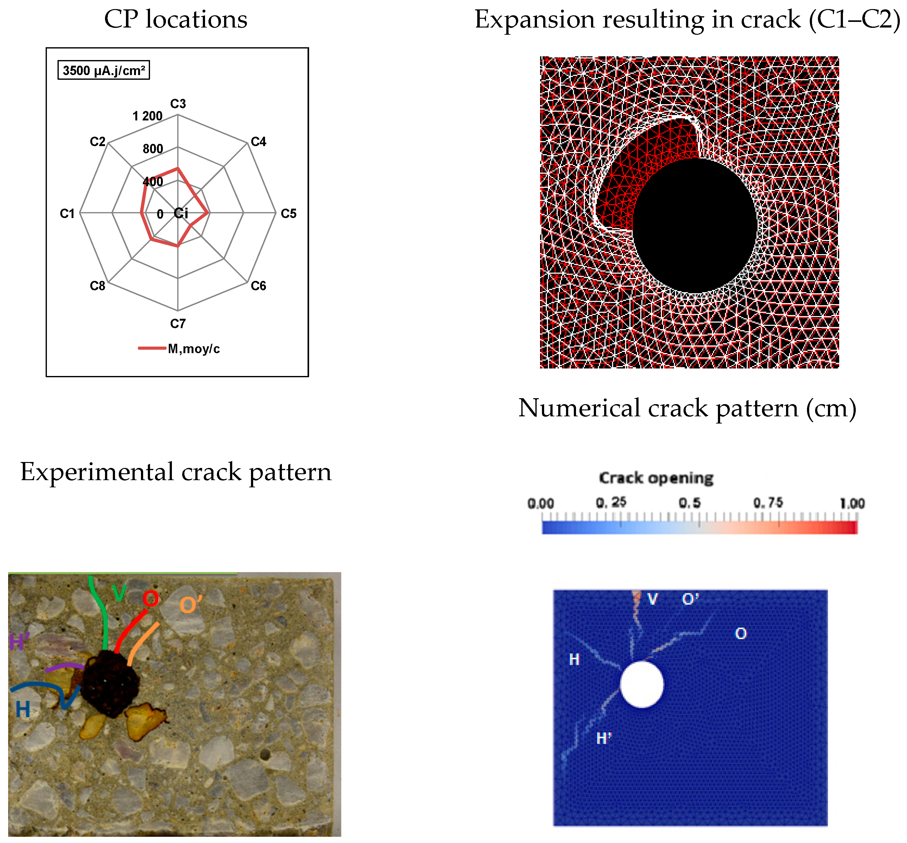
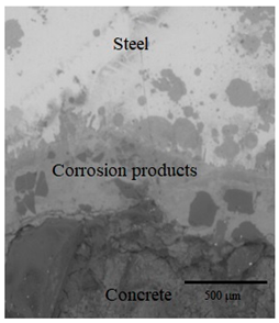
3.1.1. Thickness and Distribution of CPs Around the Steel Rebar
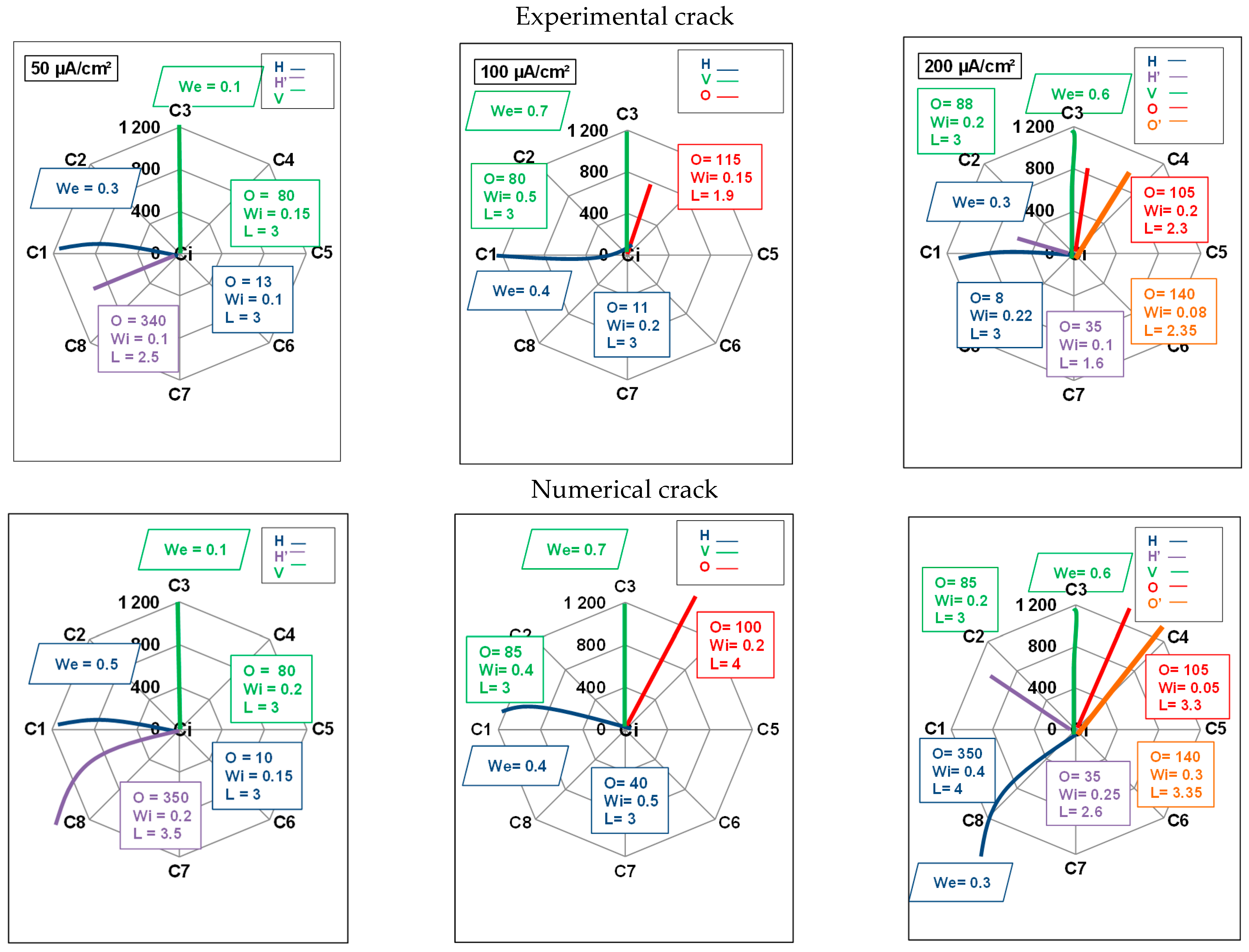
3.1.2. Evolution of Internal Cracks
- i.
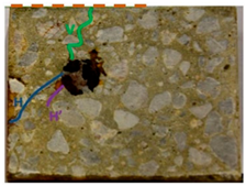
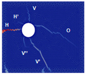
- At a current density of 50 µA/cm2, the slice had three cracks: H, H’, and V.
- ii.
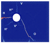
- At 100 µA/cm2, the slice showed three differently oriented cracks: H, V, and O.
- iii.
- Although the number of cracks was comparable for current densities of 50 and 100 µA/cm2, the crack patterns were distinct.
- iv.
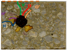
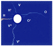
- At a current density of 200 µA/cm2, the slice developed five cracks: H, H’, V, O, and O’.
- v.
- For this current density, a higher number of cracks were observed, leading to a more severe degradation state.
3.1.3. Evolution of External Cracks
3.2. Numerical Results
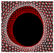
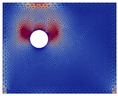
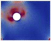
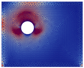
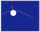
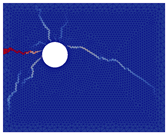
3.2.1. Influence of Numerical Expansion Type on Induced-Crack Pattern
- Semi-uniform expansion: All points in the areas (Cj) where corrosion was observed experimentally underwent an identical displacement. This displacement was equal to the average thickness of CPs measured in these areas.
- Elliptical expansion: This expansion was based on the assumption that CPs expand in an elliptical way. The thickness of CPs was measured in four directions and applied to the model accordingly.
- Homothetic expansion: This was similar to semi-uniform expansion, yet a distinct expansion value was assigned to each corroded area (Cj). This value was the average thickness as determined by experimental measurements in the designated area.
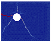
3.2.2. Influence of the Location of CP Expansion on the Crack Pattern
- Considering CP expansion in a single area (around only C3, for example).
- Considering CP expansion in two adjacent areas (around C2 and C3, for example).
- Considering CP expansion in three adjacent areas (around C1, C2, and C3, for example)
- Considering CP expansion in four adjacent areas (around C1, C2, C3, and C4, for example).
- ■
- Crack patterns varied depending on the location of CP expansion. However, they did not systematically develop in front of the initial stress concentration zones or in front of CP expansion zones when there was expansion in a single area. The expansion of two or more areas led to the formation of cracks across both dials and at the shear points due to the expansion.
- ■
- A vertical or oblique crack was observed in the thickest concrete covers (50 or 75 mm) when expansion was applied to area C8 or C4.
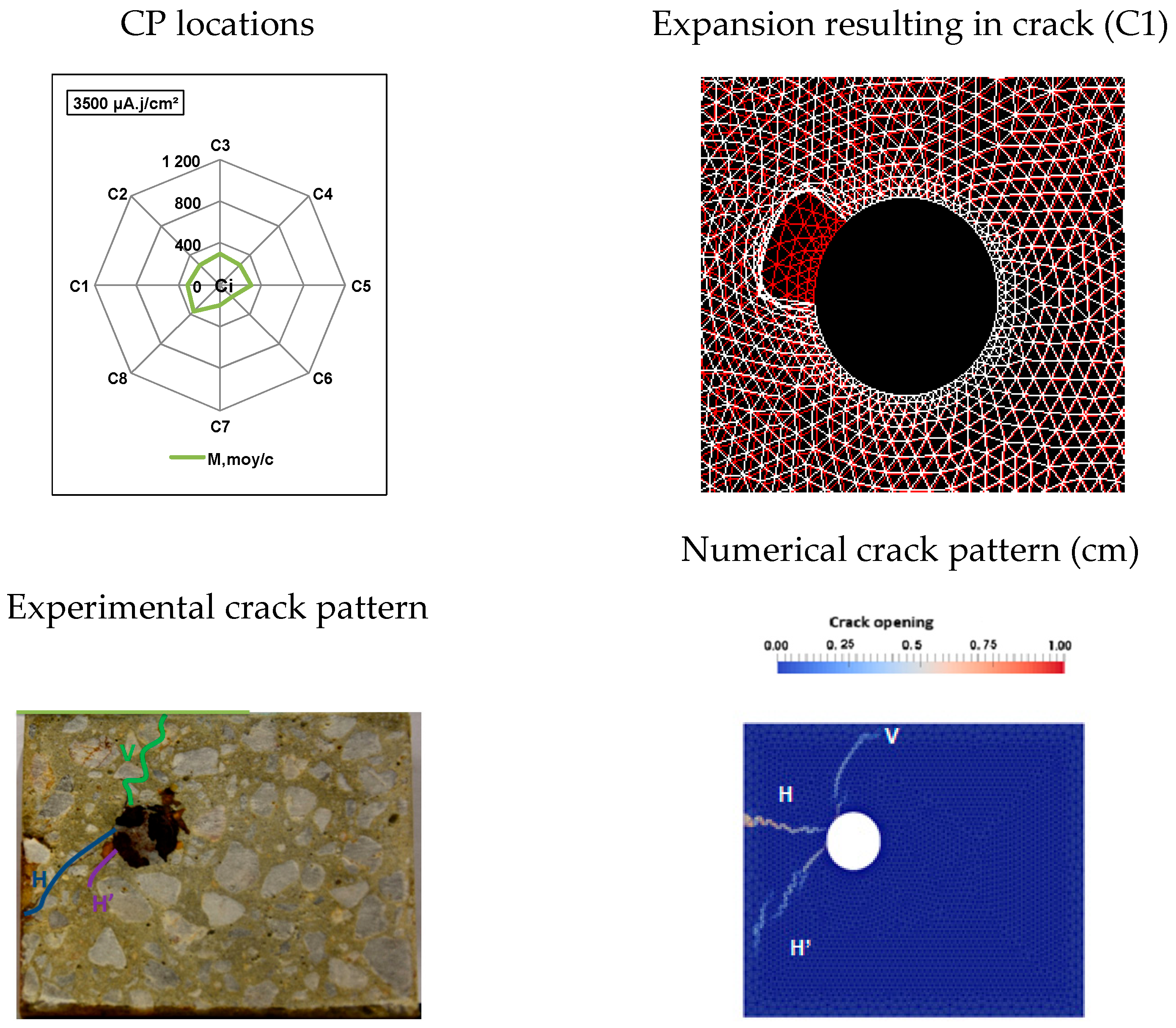
3.2.3. Determination of the Crack-Driving Expansion: An Inverse Approach
3.2.4. Quantitative Study of Internal Cracks
3.2.5. Limitations of the Numerical Modelling
4. Conclusions and Outlooks
Author Contributions
Funding
Institutional Review Board Statement
Informed Consent Statement
Data Availability Statement
Acknowledgments
Conflicts of Interest
References
- Zhang, H.; Liu, H.; Deng, Y.; Cao, Y.; He, Y.; Liu, Y.; Deng, Y. Fatigue behavior of high-strength steel wires considering coupled effect of multiple corrosion-pitting. Corros. Sci. 2025, 244, 112633. [Google Scholar] [CrossRef]
- Chen, F.; Liu, X.; Zhang, H.; Luo, Y.; Lu, N.; Liu, Y.; Xiao, X. Assessment of fatigue crack propagation and lifetime of double-sided U-rib welds considering welding residual stress relaxation. Ocean Eng. 2025, 332, 121400. [Google Scholar] [CrossRef]
- Dong, B.; Yu, Y.; Feng, Y.; Wu, D.; Zhao, G.; Liu, A.; Gao, W. Robust numerical solution for assessing corrosion of reinforced concrete structures under external power supply. Eng. Struct. 2023, 294, 116724. [Google Scholar] [CrossRef]
- Lliso-Ferrando, J.R.; Gasch, I.; Martínez-Ibernón, A.; Valcuende, M. Effect of macrocell currents on rebar corrosion in reinforced concrete structures exposed to a marine environment. Ocean Eng. 2022, 257, 111680. [Google Scholar] [CrossRef]
- Nasser, H.; Vandewalle, L.; Verstrynge, E. Effect of pre-existing longitudinal and transverse corrosion cracks on the flexural behaviour of corroded RC beams. Constr. Build. Mater. 2022, 319, 126141. [Google Scholar] [CrossRef]
- Haefliger, S.; Kaufmann, W. Influence of cross section loss on the stress-strain characteristics of corroded quenched and self-tempered reinforcing bars. Constr. Build. Mater. 2021, 282, 122598. [Google Scholar] [CrossRef]
- Rosso, M.M.; Asso, R.; Aloisio, A.; Di Benedetto, M.; Cucuzza, R.; Greco, R. Corrosion effects on the capacity and ductility of concrete half-joint bridges. Constr. Build. Mater. 2022, 360, 129555. [Google Scholar] [CrossRef]
- Daneshvar, K.; Moradi, M.J.; Ahmadi, K.; Hajiloo, H. Strengthening of corroded reinforced concrete slabs under multi-impact loading: Experimental results and numerical analysis. Constr. Build. Mater. 2021, 284, 122650. [Google Scholar] [CrossRef]
- Dackman, D.; Berrocal, C.G.; Rempling, R.; Fernandez, I. A framework for evaluating steel loss from the evolution of corrosion-induced deflections in reinforced concrete beams with non-uniform reinforcement corrosion. Eng. Struct. 2024, 317, 118593. [Google Scholar] [CrossRef]
- Rodriguez, J.; Ortega, L.M.; Garcfa, A.M. Assessment of structural elements with corroded reinforcement. In Proceedings of the International Conference of Corrosion and Protection of Steel in Concrete, Sheffield, UK, 24–28 July 1994. [Google Scholar]
- Imam, A.; Mishra, S.; Bind, Y.K. Review study towards corrosion mechanism and its impact on the durability of concrete structures. AIMS Mater. Sci. 2018, 5, 276–300. [Google Scholar] [CrossRef]
- Koulouris, K.; Charalampopoulos, A.; Apostolopoulos, C.A. Simulation of the degraded (steel—Concrete) bond strength due to corrosion via modeling pull out tests. J. Phys. Conf. Ser. 2024, 2692, 012002. [Google Scholar] [CrossRef]
- Wang, W.; Liu, B.; Tan, G.; Liu, H.; Jiao, Y.; Lv, D.; Wang, H.; Shi, D.; Zhang, S. Bond damage evolution and spatial micro-mechanism analysis of corroded reinforced concrete and failure mode assessment by acoustic emission. J. Mater. Res. Technol. 2025, 37, 1086–1105. [Google Scholar] [CrossRef]
- Nasser, H.; Van Steen, C.; Vandewalle, L.; Verstrynge, E. An experimental assessment of corrosion damage and bending capacity reduction of singly reinforced concrete beams subjected to accelerated corrosion. Constr. Build. Mater. 2021, 286, 122773. [Google Scholar] [CrossRef]
- Xia, M.; Guo, R.; Lin, Q.; Yu, Z. Prediction model for the bond behaviour of low-corrosion reinforced concrete considering corrosion time variability. Constr. Build. Mater. 2024, 444, 137891. [Google Scholar] [CrossRef]
- Liu, C.; Zheng, J.; Ning, N.; Yan, L.; Zheng, C. Experimental study of bond performance of corroded reinforcement in concrete under various cooling methods. J. Build. Eng. 2024, 84, 108569. [Google Scholar] [CrossRef]
- Zhang, Y.-B.; Zheng, S.-S.; Ji, J.-M.; Zheng, Y.; Wang, B. Bond performance of coupling corrosion of main reinforcement and stirrups in concrete under reversed cyclic loading. Structures 2025, 71, 107978. [Google Scholar] [CrossRef]
- Robuschi, S. Natural Corrosion in Reinforced Concrete Structures. Ph.D Thesis, Chalmers University of Technology, Göteborg, Sweden, 1930. [Google Scholar]
- Zeng, B.; Wang, Y.; Gong, F.; Maekawa, K. Corrosion-Induced cracking pattern analysis of RC beam under sustained load considering the poromechanical characteristics of corrosion products. Buildings 2022, 12, 2256. [Google Scholar] [CrossRef]
- Sanz Merino, B. Experimental and Numerical Study of Cracking of Concrete due to Reinforcement Corrosion. Ph.D. Thesis, Universidad Politécnica de Madrid, Madrid, Spain, 2014. [Google Scholar]
- Bhargava, K.; Ghosh, A.K.; Mori, Y.; Ramanujam, S. Analytical model for time to cover cracking in RC structures due to rebar corrosion. Nucl. Eng. Des. 2006, 236, 1123–1139. [Google Scholar] [CrossRef]
- German, M.; Pamin, J. Numerical Simulation of Non-Uniformly Distributed Corrosion in Reinforced Concrete Cross-Section. Materials 2021, 14, 3975. [Google Scholar] [CrossRef]
- Nguyen, V.C.; Bui, Q.H.; Lambert, P. Experimental and numerical evaluation of the structural performance of corroded reinforced concrete beams under different corrosion schemes. Structures 2022, 45, 2318–2331. [Google Scholar] [CrossRef]
- Fuhaid, A.F.A.; Niaz, A. Carbonation and Corrosion Problems in Reinforced Concrete Structures. Buildings 2022, 12, 586. [Google Scholar] [CrossRef]
- Yang, J.; Haghani, R.; Blanksvärd, T.; Lundgren, K. Experimental study of FRP-strengthened concrete beams with corroded reinforcement. Constr. Build. Mater. 2021, 301, 124076. [Google Scholar] [CrossRef]
- Yu, Y.; Xu, J.; Sun, B.; Lin, L.; Wang, Y. Investigating non-uniform corrosion induced concrete cover cracking with a fracture-contact coupled computational method. Constr. Build. Mater. 2024, 415, 135105. [Google Scholar] [CrossRef]
- El Alami, E.; Fekak, F.-E.; Garibaldi, L.; Elkhalfi, A. A numerical study of pitting corrosion in reinforced concrete structures. J. Build. Eng. 2021, 43, 102789. [Google Scholar] [CrossRef]
- Du, T.; Xiao, J.; Li, C.; Gan, Y.; Jiang, X. Experimental and numerical study on the chloride ions penetration in recycled aggregate concrete. Constr. Build. Mater. 2024, 451, 138702. [Google Scholar] [CrossRef]
- Molina, F.J.; Alonso, C.; Andrade, C. Cover cracking as a function of rebar corrosion: Part 2 Numerical model. Mater. Struct. 1993, 26, 532–548. [Google Scholar] [CrossRef]
- Andrade, C.; Alonso, C.; Molina, F.J. Cover cracking as a function of bar corrosion: Part I-Experimental test. Mater. Struct. 1993, 26, 453–464. [Google Scholar] [CrossRef]
- Vu, B.-T.; Nguyen, D.-D.; Tran, T.-T.; Tran, D.-N.; Nguyen, N.-L.; Bui, T.-T.; Nguyen, X.-L. Phase-field modeling for investigating the effect of rebar positioning and uniform versus non-uniform corrosion on concrete fracture. Fract. Struct. Integr. 2025, 19, 166–180. [Google Scholar] [CrossRef]
- Mikael, D. Etude du Comportement Mécanique des Structures en Béton Armé Dégradé par la Corrosion. Ph.D. Thesis, Univeristé de Lille 1, Villeneuve-d’Ascq, France, 2003. [Google Scholar]
- Millard, A.; L’Hostis, V.; Beddiar, K.; Berthaud, Y.; Care, S. Modelling the Cracking of a Reinforced Concrete Structure Submitted to Corrosion; Rilem—DOCE: Barcelona, Spain, 2004. [Google Scholar]
- L’Hostis, V.; Foct, F.; Dillmann, P. Corrosion behaviour of reinforced concrete: Laboratory experiments and archaeological analogues for long-term predictive modelling. J. Nucl. Mater. 2008, 379, 124–132. [Google Scholar] [CrossRef]
- Richard, B.; Quiertant, M.; Bouteiller, V.; Adelaide, L.; Tailhan, J.L.; Cremona, C. Influence of accelerated corrosion on the reinforced cover concrete cracking behavior: Experimental and numerical study. Eur. J. Environ. Civ. Eng. 2012, 16, 450–459. [Google Scholar] [CrossRef]
- Lundgren, K. Initial Cross-Section Bond Between Corroded Reinforcement and Concrete; Chalmers: University of Technology: Göteborg, Sweden, 2001. [Google Scholar]
- François, R. A discussion on the order of magnitude of corrosion current density in reinforcements of concrete structures and its link with cross-section loss of reinforcement. Rilem Tech. Lett. 2021, 6, 158–168. [Google Scholar] [CrossRef]
- Chen, J.; Zhang, W.; Tang, Z.; Huang, Q. Experimental and numerical investigation of chloride-induced reinforcement corrosion and mortar cover cracking. Cem. Concr. Compos. 2020, 111, 103620. [Google Scholar] [CrossRef]
- Xu, W.; Zhang, C.; Li, Y. Simulation and analysis of rust expansion cracking of reinforced concrete. Constr. Build. Mater. 2024, 426, 136199. [Google Scholar] [CrossRef]
- Zhao, J.; Chen, Z.; Mehrmashhadi, J.; Bobaru, F. A stochastic multiscale peridynamic model for corrosion-induced fracture in reinforced concrete. Eng. Fract. Mech. 2020, 229, 106969. [Google Scholar] [CrossRef]
- Zhu, X.; Meng, Z.; Liu, L.; Xu, L. An equivalent smeared layer method for simulating the non-uniform corrosion-induced damage of concrete. Eng. Fract. Mech. 2020, 224, 106791. [Google Scholar] [CrossRef]
- Jin, L.; Liu, M.; Zhang, R.; Du, X. Cracking of cover concrete due to non-uniform corrosion of corner rebar: A 3D meso-scale study. Constr. Build. Mater. 2020, 245, 118449. [Google Scholar] [CrossRef]
- Zeng, C.; Zheng, Z.; Zhang, H.; Huang, Y.; Wang, X.; Liu, G. 3D mesoscale investigation of non-uniform steel corrosion in reinforced concrete under chloride environments. Constr. Build. Mater. 2024, 411, 134273. [Google Scholar] [CrossRef]
- Zhu, W.; Ren, Y.; Yu, Z.; Tang, F.; Xu, Y.; Xu, Y. Characteristics of the non-uniform corrosion of the steel bars extracted from the marine transportation infrastructures. J. Build. Eng. 2024, 87, 109108. [Google Scholar] [CrossRef]
- Qiao, D.; Nakamura, H.; Yamamoto, Y.; Miura, T. Crack patterns of concrete with a single rebar subjected to non-uniform and localized corrosion. Constr. Build. Mater. 2016, 116, 366–377. [Google Scholar] [CrossRef]
- Zhao, Y.; Karimi, A.R.; Wong, H.S.; Hu, B.; Buenfeld, N.R.; Jin, W. Comparison of uniform and non-uniform corrosion induced damage in reinforced concrete based on a Gaussian description of the corrosion layer. Corros. Sci. 2011, 53, 2803–2814. [Google Scholar] [CrossRef]
- Du, X.; Jin, L.; Zhang, R. Modeling the cracking of cover concrete due to non-uniform corrosion of reinforcement. Corros. Sci. 2014, 89, 189–202. [Google Scholar] [CrossRef]
- Xi, X.; Yang, S.; Li, C.Q. A non-uniform corrosion model and meso-scale fracture modelling of concrete. Cem. Concr. Res. 2018, 108, 87–102. [Google Scholar] [CrossRef]
- Wu, B.; Xu, K.; Yang, M.; Dong, Z.; Shao, J.; Fu, C.; Ni, W. Analysis of Circumferential and Longitudinal Non-Uniformity of Steel Corrosion in Concrete Subjected to Mechanical Load. Buildings 2024, 14, 509. [Google Scholar] [CrossRef]
- Sun, W.; Zou, W.; Bao, S.; Du, Q.; Song, R. Modeling concrete cracking induced by non-uniform rebar corrosion using experiments and mesoscale peridynamics. Comput. Part. Mech. 2025. [Google Scholar] [CrossRef]
- Sutrisno, W.; Suprobo, P.; Wahyuni, E.; Iranata, D. Investigation of Non-Uniform Rust Distribution and Its Effects on Corrosion Induced Cracking in Reinforced Concrete. In MATEC Web of Conferences; EDP Sciences: Les Ulis, France, 2017. [Google Scholar] [CrossRef]
- Zhao, Y.; Zhang, X.; Ding, H.; Jin, W. Non-uniform distribution of a corrosion layer at a steel/concrete interface described by a Gaussian model. Corros. Sci. 2016, 112, 1–12. [Google Scholar] [CrossRef]
- Zhao, Y.; Ren, H.; Dai, H.; Jin, W. Composition and expansion coefficient of rust based on X-ray diffraction and thermal analysis. Corros. Sci. 2011, 53, 1646–1658. [Google Scholar] [CrossRef]
- Taheri-Shakib, J.; Al-Mayah, A. 4D evolutions of cracks, voids, and corrosion products in reinforced concrete materials. Sci. Rep. 2023, 13, 22455. [Google Scholar] [CrossRef]
- Ma, Y.; Yang, J.; Su, X.; Peng, A.; Wang, L.; Huang, K. Crack propagation characterization of concrete under non-uniform corrosion of steel strand using digital image correlation. Constr. Build. Mater. 2024, 455, 139166. [Google Scholar] [CrossRef]
- Pantazopoulou, B.S.J.; Papoulia, K.D. Modeling cover-cracking due to reinforcement corrosion in RC structures. J. Eng. Mech. 2001, 127, 342–351. [Google Scholar] [CrossRef]
- Malumbela, G.; Alexander, M.; Moyo, P. Model for cover cracking of RC beams due to partial surface steel corrosion. Constr. Build. Mater. 2011, 25, 987–991. [Google Scholar] [CrossRef]
- Loukil, O. Etude Expérimentale et Numérique de la Dégradation D’éléments Structurels en Béton Armé par Corrosion sous Courant Imposé’. Ph.D. Thesis, Science, Ingénierie et Environnement, Université Paris-Est, Créteil, France, 2017. [Google Scholar]
- Loukil, O.; Adelaide, L.; Bouteiller, V.; Quiertant, M.; Ragueneau, F.; Chaussadent, T. Investigation of Corrosion Product Distribution and Induced Cracking Patterns in Reinforced Concrete Using Accelerated Corrosion Testing. Appl. Sci. 2024, 14, 11453. [Google Scholar] [CrossRef]
- Pedrosa, F.; Andrade, C. Corrosion induced cracking: Effect of different corrosion rates on crack width evolution. Constr. Build. Mater. 2017, 133, 525–533. [Google Scholar] [CrossRef]
- Malumbela, G.; Alexander, M.; Moyo, P. Interaction between corrosion crack width and steel loss in RC beams corroded under load. Cem. Concr. 2010, 40, 1419–1428. [Google Scholar] [CrossRef]
- Van Steen, C.; Pahlavan, L.; Wevers, M.; Verstrynge, E. Localisation and characterisation of corrosion damage in reinforced concrete by means of acoustic emission and X-ray com-puted tomography. Constr. Build. Mater. 2019, 197, 21–29. [Google Scholar] [CrossRef]
- Caré, S.; Nguyen, Q.T.; Beddiar, K.; Berthaud, Y. Times to cracking in reinforced mortar beams subjected to accelerated corrosion tests. Mater. Struct./Mater. Constr. 2010, 43, 107–124. [Google Scholar] [CrossRef]
- Zhang, W.; Chen, J.; Luo, X. Effects of impressed current density on corrosion induced cracking of concrete cover. Constr. Build. Mater. 2019, 204, 213–223. [Google Scholar] [CrossRef]
- Loukil, O. Corrosion-Induced Degradation of Reinforced Concrete Elements: Preliminary Results. In 8th International Rilem Phd Workshop; Rilem, Ed.; Springer: Marne la vallée, France, 2019; pp. 129–140. [Google Scholar]
- Mazars, J. A description of micro and acroscale damage of concrete structures. Eng. Fract. Mech. 1986, 25, 729–737. [Google Scholar] [CrossRef]
- Hillerborg, A.; Modéer, M.; Petersson, P.-E. Analysis of crack formation and crack growth in concrete by means of fracture mechanics and finite elements. Cem. Concr. Res. 1976, 6, 773–782. [Google Scholar] [CrossRef]
- Matallah, M.; La Borderie, C.; Maurel, O. A practical method to estimate crack openings in concrete structures. Int. J. Numer. Anal. Methods Geomech. 2010, 34, 1615–1633. [Google Scholar] [CrossRef]
- Laborderie, C.; Maurel, O.; Matalllah, M. Couplage endommagement fissuration: Applications aux calculs de structures en béton armé. In Proceedings of the 19 ème Congrès Français de Mécanique, Marseille, France, 24–28 August 2009. [Google Scholar]
- Fang, G.; Ding, W.; Liu, Y.; Zhang, J.; Xing, F.; Dong, B. Identification of corrosion products and 3D distribution in reinforced concrete using X-ray micro computed tomography. Constr. Build. Mater. 2019, 207, 304–315. [Google Scholar] [CrossRef]
- Ghanti, R. Effect of Impressed Current on the Microstructure of Corroded Steel-Concrete Interface; Imperial College London: London, UK, 2012; p. 13. [Google Scholar]
- Xu, X.; Zhao, Y. Corrosion-induced cracking propagation of RC beams subjected to different corrosion methods and load levels. Constr. Build. Mater. 2021, 286, 122913. [Google Scholar] [CrossRef]
- Zhao, Y.; Yu, J.; Wu, Y.; Jin, W. Critical thickness of rust layer at inner and out surface cracking of concrete cover in reinforced concrete structures. Corros. Sci. 2012, 59, 316–323. [Google Scholar] [CrossRef]
- Cornell, R.M.; Schwertmann, U. The Iron Oxides Structure, Properties, Reactions, Occurrence and Uses; Wiley-VCH Verlag GmbH & Co. KGaA: Weinheim, Germany, 2003. [Google Scholar]
- Ožbolt, J.; Oršanić, F.; Balabanić, G. Modeling pull-out resistance of corroded reinforcement in concrete: Coupled three-dimensional finite element model. Cem. Concr. Compos. 2014, 46, 41–55. [Google Scholar] [CrossRef]
- Fischer, C.; Leipzig, A. Auswirkungen der Bewehrungskorrosion auf den Verbund Zwischen Stahl und Beton. Ph.D. Thesis, Institut für Werkstoffe im Bauwesen der Universität Stuttgart, Stuttgart, Germany, 2012. [Google Scholar]


| Minimum Thickness of CPs | Maximum Thickness of CPs | |||
|---|---|---|---|---|
| RC Prism Pn-Y-Xd | Thickness (µm) | Location (Cj) | Thickness (µm) | Location (Ci) |
| P27-50-70d | 23 | C1 | 873 | C2 |
| P11-100-35d | 111 | C1 | 1584 | C8 |
| P17-200-17.5d | 28 | C4 | 1228 | C3 |
| P27-T14R-50-70d | P11-T11R-100-35d | P17-T13R-200-17.5d |
|---|---|---|
 |  |  |
| Current Density (µA/cm2) | T | F | |
|---|---|---|---|
| 50 | P027*-70d | 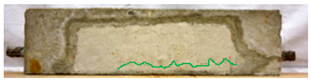 |  |
| P028-70d | 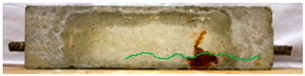 | 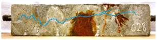 | |
| 100 | P011*-35d |  | 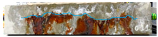 |
| P012-35d | 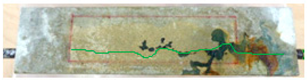 | 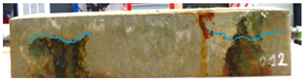 | |
| 200 | P017*-17.5d |  |  |
| P018-17.5d |  | 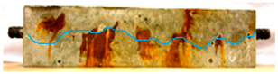 | |
 |  | ||||
| a/ | b/ | ||||
| Semi-uniform expansion | Elliptical expansion | Homothetic expansion | |||
 |  |  | |||
| Experimental Crack Patterns | Semi-Uniform Expansion | Elliptical Expansion | Homothetic Expansion |
|---|---|---|---|
Simulated Crack Pattern Map | |||
 |  |  |  |
| Maximum Expansion Percentage | Semi-Uniform Expansion | Homothetic Expansion | Elliptical Expansion |
|---|---|---|---|
| Simulated Crack Pattern Map | |||
 | |||
| 25% | 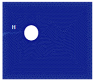 | 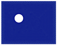 | 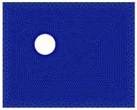 |
| Scenario 1 | Scenario 2 | Scenario 3 | Scenario 4 | Scenario 5 |
|---|---|---|---|---|
| Imposed Displacement | ||||
| 400 µm | 400 µm | 400 µm | 350 µm | 400 µm |
 | 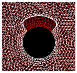 | 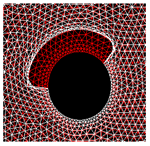 |  | 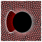 |
Stress mapping (before crack initiation) 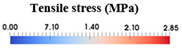 | ||||
 |  |  |  |  |
Numerical crack pattern  | ||||
 |  |  |  |  |
Disclaimer/Publisher’s Note: The statements, opinions and data contained in all publications are solely those of the individual author(s) and contributor(s) and not of MDPI and/or the editor(s). MDPI and/or the editor(s) disclaim responsibility for any injury to people or property resulting from any ideas, methods, instructions or products referred to in the content. |
© 2025 by the authors. Licensee MDPI, Basel, Switzerland. This article is an open access article distributed under the terms and conditions of the Creative Commons Attribution (CC BY) license (https://creativecommons.org/licenses/by/4.0/).
Share and Cite
Loukil, O.; Adelaide, L.; Bouteiller, V.; Quiertant, M. Experimental and Numerical Analysis of Corrosion-Induced Cracking in Reinforced Concrete. Appl. Mech. 2025, 6, 57. https://doi.org/10.3390/applmech6030057
Loukil O, Adelaide L, Bouteiller V, Quiertant M. Experimental and Numerical Analysis of Corrosion-Induced Cracking in Reinforced Concrete. Applied Mechanics. 2025; 6(3):57. https://doi.org/10.3390/applmech6030057
Chicago/Turabian StyleLoukil, Olfa, Lucas Adelaide, Veronique Bouteiller, and Marc Quiertant. 2025. "Experimental and Numerical Analysis of Corrosion-Induced Cracking in Reinforced Concrete" Applied Mechanics 6, no. 3: 57. https://doi.org/10.3390/applmech6030057
APA StyleLoukil, O., Adelaide, L., Bouteiller, V., & Quiertant, M. (2025). Experimental and Numerical Analysis of Corrosion-Induced Cracking in Reinforced Concrete. Applied Mechanics, 6(3), 57. https://doi.org/10.3390/applmech6030057