Dynamic Stress Wave Response of Thin-Walled Circular Cylindrical Shell Under Thermal Effects and Axial Harmonic Compression Boundary Condition

 , and
, and
Abstract
1. Introduction
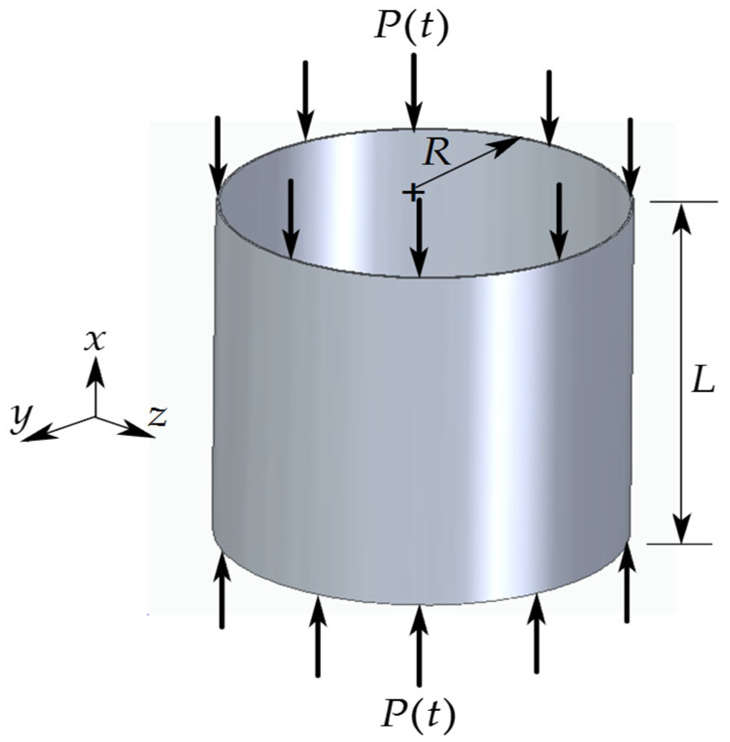
2. Proposed Modelling of Thin-Walled Circular Cylindrical Shells
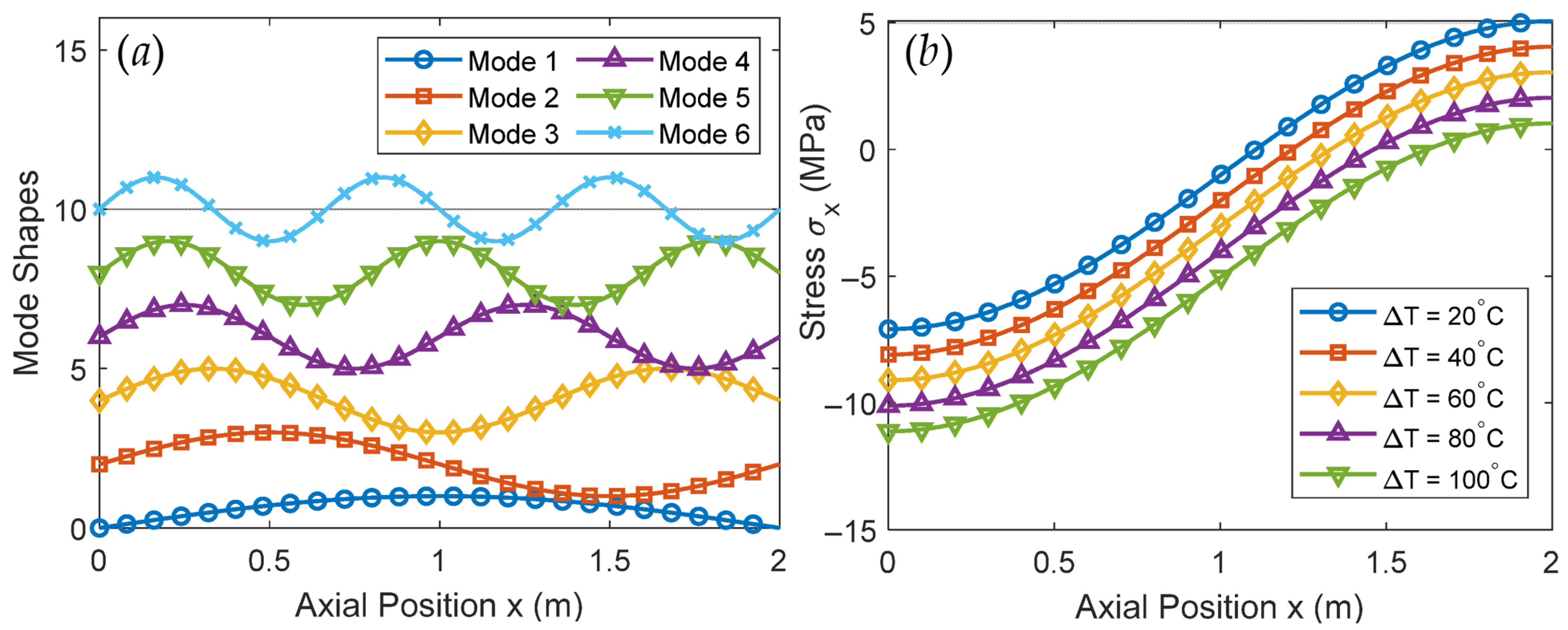
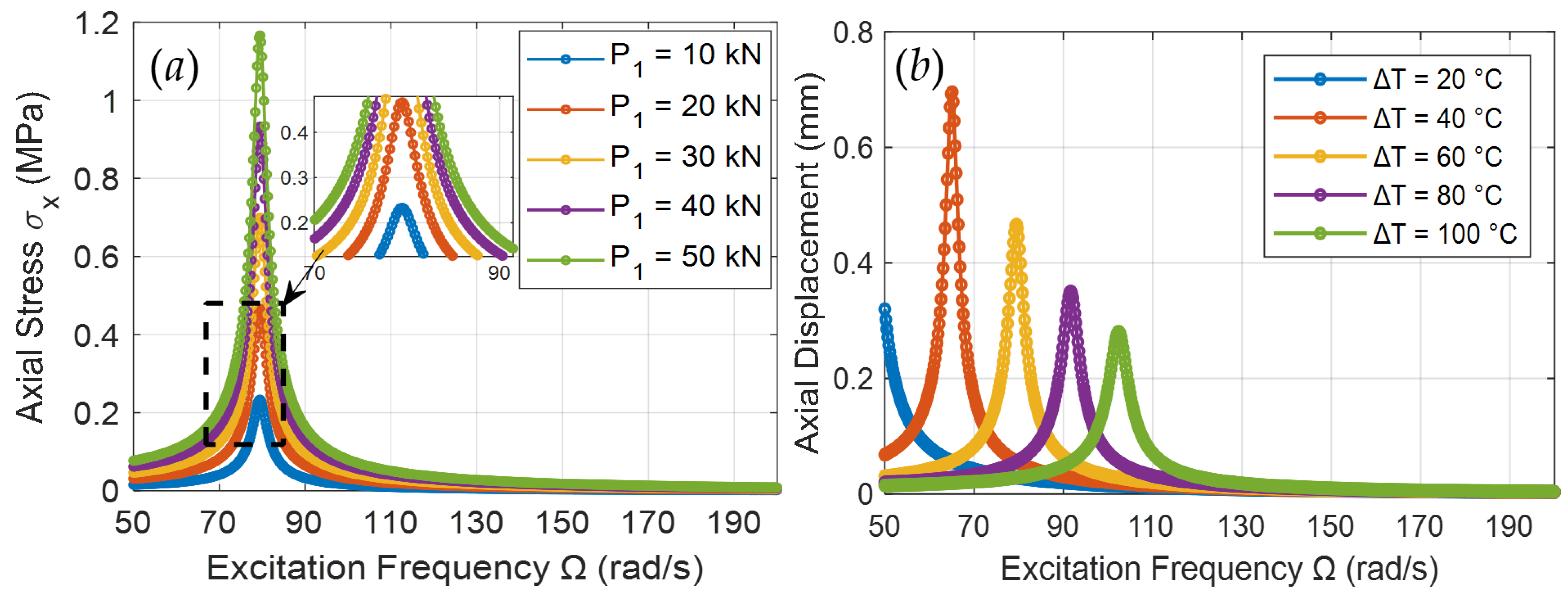
3. Dynamic Response of the Analytical Thin-Walled Circular Cylindrical Shell System
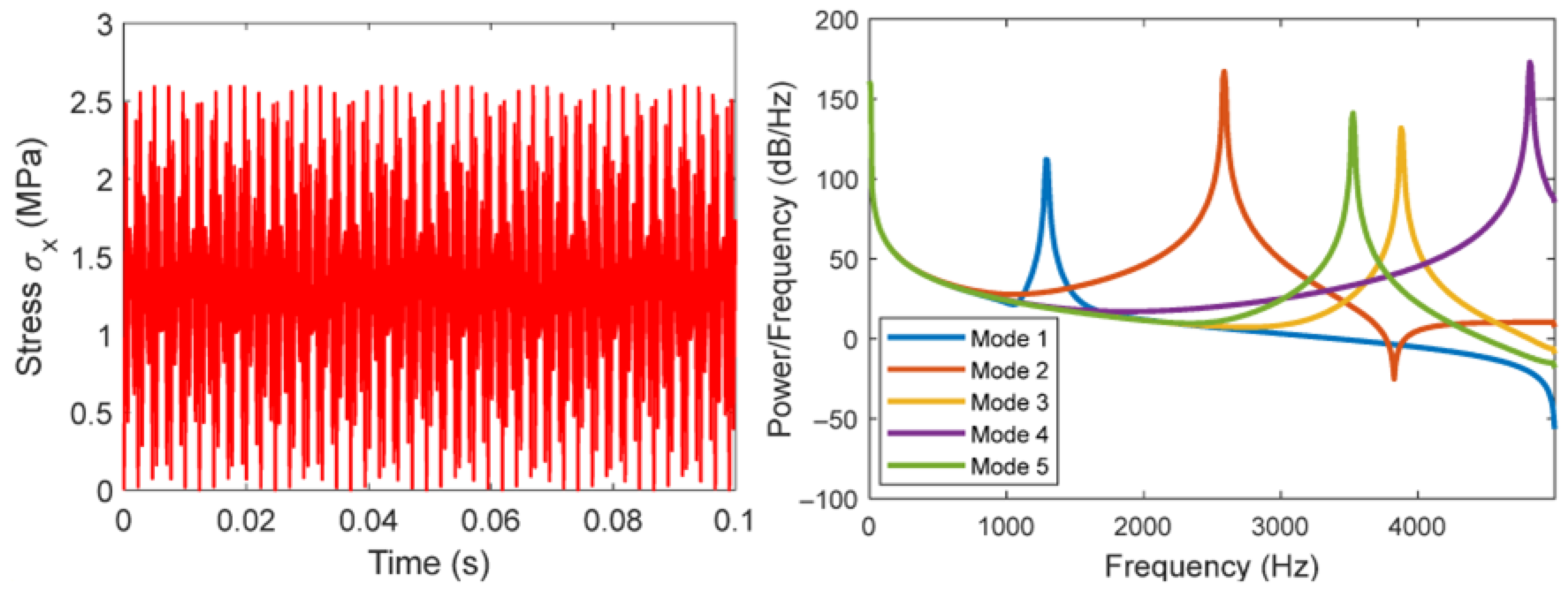
4. Power Spectral Density Model
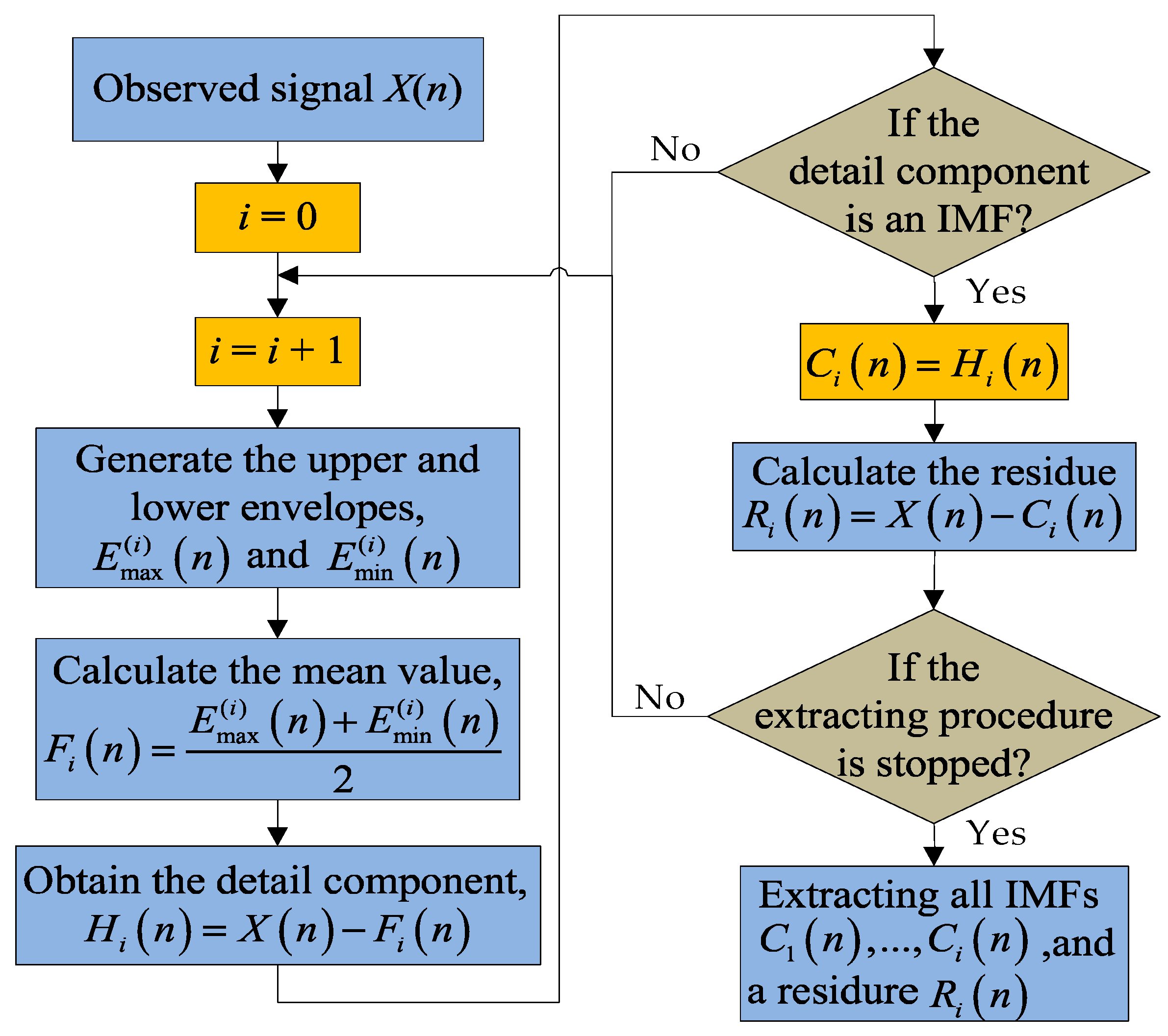
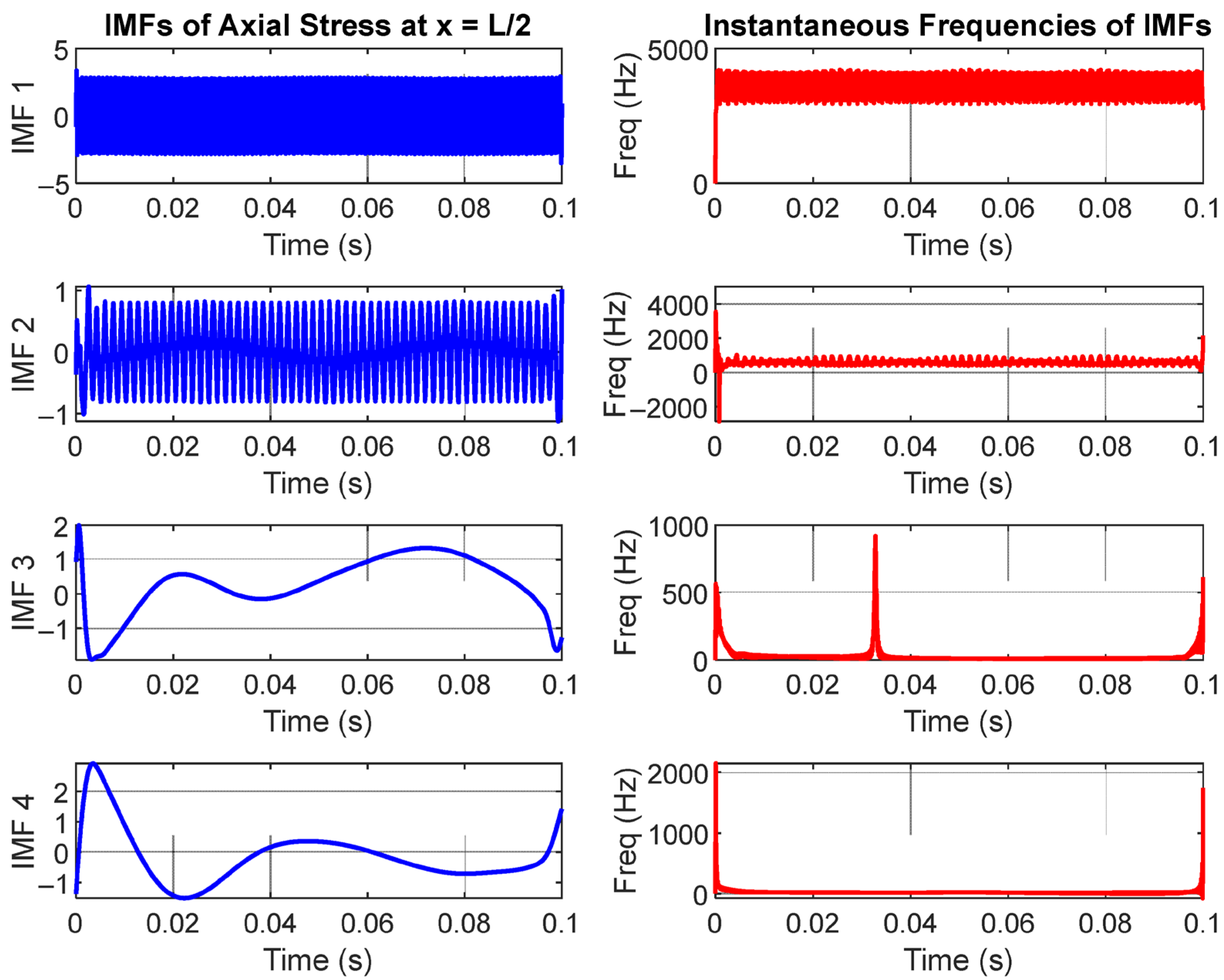
5. Empirical Mode Decomposition and Instantaneous Frequency of the Time Domain Response
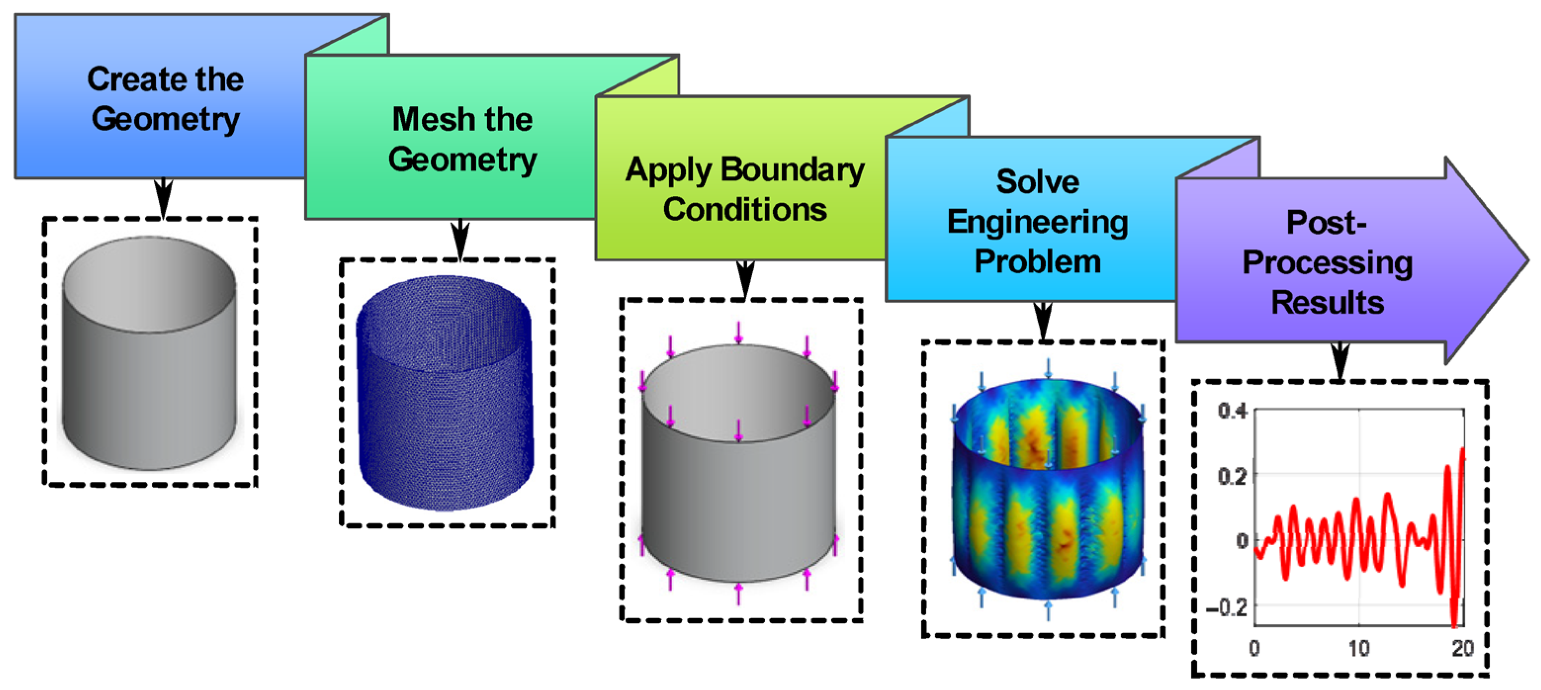
6. Finite Element Modal Analysis
7. Conclusions
Author Contributions
Funding
Institutional Review Board Statement
Informed Consent Statement
Data Availability Statement
Acknowledgments
Conflicts of Interest
Nomenclature
| Symbol | Description | Unit |
| P0 | Static component of axial load | N |
| P1 | Dynamic amplitude of axial load | N |
| ω | Angular excitation frequency | rad/s |
| T0 | Mean reference temperature | °C |
| ΔT | Thermal increment/temperature variation | °C |
| Ω | Frequency of thermal variation | rad/s |
| u(x,t) | Axial displacement as a function of position and time | m |
| σx(x,t) | Axial stress distribution | N/m2 |
| Un(t) | Modal amplitude for the nth mode | m |
| ωn | Natural frequency of the nth axial vibration mode | rad/s |
| Ux,Uy,Uz | Displacement components in global Cartesian directions | mm |
| S(f) | Power spectral density (PSD) function | dB/Hz |
| τ | Time lag variable (for autocorrelation/PSD computation) | s |
| IMFn | nth intrinsic mode function from EMD | – |
| f | Frequency | Hz |
| X(t) | Time-domain stress signal | – |
| R(τ) | Autocorrelation function of signal | – |
| F{⋅} | Fourier transform operator | – |
| IF | Instantaneous frequency | Hz |
| G | Shear modulus | GPa |
| θ | Circumferential coordinate (used in modal shapes) | rad |
References
- Cammalleri, M.; Castellano, A. A Dynamic Matrix for the Study of Free Vibrations of Thin Circular Cylindrical Shells under Different Boundary Conditions. Designs 2023, 7, 122. [Google Scholar] [CrossRef]
- Yücel, H.; Erbaş, B.; Ege, N.; Kaplunov, J. The lowest eigenfrequencies of an immersed thin elastic cylindrical shell. In Advances in Linear and Nonlinear Continuum and Structural Mechanics; Springer Nature: Cham, Switzerland, 2023; pp. 559–571. [Google Scholar]
- Hart, E.L.; Semencha, O.O. Numerical Analysis of the Effect of Tape Inclusions on the Stress Concentration in Thin cylindrical and Conical Shells with Rectangular Openings. Tech. Mech. 2024, 1, 66–82. [Google Scholar] [CrossRef]
- Fan, Z.; Ge, S.; Yue, Z.; Yu, R.; Li, B.; Jiao, J.; Liu, J.; Zhang, Q. Dynamic response of clamped metallic thin-walled cylindrical shells under lateral shock loading. Thin-Walled Struct. 2024, 200, 111922. [Google Scholar] [CrossRef]
- Sun, W.; Zhu, T.; Chen, P.; Lin, G. Dynamic implosion of submerged cylindrical shell under the combined hydrostatic and shock loading. Thin-Walled Struct. 2022, 170, 108574. [Google Scholar] [CrossRef]
- Zhang, G.Y.; Gao, X.L.; Littlefield, A.G. A non-classical model for circular cylindrical thin shells incorporating microstructure and surface energy effects. Acta Mech. 2021, 232, 2225–2248. [Google Scholar] [CrossRef]
- Akhmedov, S.; Tursunov, I.; Safarov, U.; Boltayev, S.A.; Hakimov, S. Natural vibrations of reinforced viscoelastic cylindrical shells with a viscoelastic filler. Part 1. AIP Conf. Proc. 2022, 2647, 030005. [Google Scholar] [CrossRef]
- Sagdiyev, K.; Boltayev, Z.; Ruziyev, T.; Jurayev, U.; Jalolov, F. Dynamic Stress-Deformed States of a Circular Tunnel of Small Position Under Harmonic Disturbances. E3S Web Conf. 2021, 264, 01028. [Google Scholar] [CrossRef]
- Zhang, J.; Zhang, W.; Zhang, Y.F. Nonlinear vibrations of porous-hyperelastic cylindrical shell under harmonic force using harmonic balance and pseudo-arc length continuation methods. Thin-Walled Struct. 2024, 198, 111767. [Google Scholar] [CrossRef]
- Lu, K.; Chen, X.; Pang, X.; Liu, F. Time-varying vibration characteristics and surface topography of thin-walled cylinders during machining operations. Measurement 2024, 232, 114725. [Google Scholar] [CrossRef]
- Qi, L.; Zhu, M.; Gao, Q.; Zhang, Y.; Fu, G.; Cui, Q.; Gao, S.; Wei, W.; Wang, L.; Lu, L. Coupling effect of machine tool dynamic characteristics and cutting conditions on the cutting process vibration and high-speed micro-planing surface mid-frequency waviness. Mech. Syst. Signal Process. 2024, 216, 111499. [Google Scholar] [CrossRef]
- Deng, T.; Zhang, B.; Liu, J.; Shen, H.; Zhang, X. Vibration frequency and mode localization characteristics of strain gradient variable-thickness microplates. Thin-Walled Struct. 2024, 199, 111779. [Google Scholar] [CrossRef]
- Amabili, M.; Moghaddasi, H.R. Non-linear dynamics of cantilevered circular cylindrical shells with thickness stretch, containing quiescent fluid with small-amplitude sloshing. J. Sound Vib. 2024, 571, 118052. [Google Scholar] [CrossRef]
- Zhdanov, A.A.; Petrov, V.N. Stress-deformed state of vertical cylindrical metal shell under temperature climate impact. IOP Conf. Ser. Mater. Sci. Eng. 2021, 1164, 012092. [Google Scholar] [CrossRef]
- Zippo, A.; Barbieri, M.; Iarriccio, G.; Pellicano, F. Nonlinear vibrations of circular cylindrical shells with thermal effects: An experimental study. Nonlinear Dyn. 2020, 99, 373–391. [Google Scholar] [CrossRef]
- Tomczyk, B.; Gołąbczak, M.; Gołąbczak, A. A new combined asymptotic-tolerance model of thermoelasticity problems for thin uniperiodic cylindrical shells. Contin. Mech. Thermodyn. 2024, 36, 1–26. [Google Scholar] [CrossRef]
- Sozinando, D.F.; Leema, K.K.; Sigonde, V.C.; Tchomeni, B.X.; Alugongo, A.A. Stress Distribution and Transverse Vibration of Flywheel Within Linear Elastic Range. Vibration 2024, 7, 1248–1265. [Google Scholar] [CrossRef]
- Li, H.; Deng, Y.; Zhao, S.; Qin, Z.; Wang, L.; Xiang, Y.; Du, D.; Wu, H. Thermal-vibration ageing characteristics of three thin-walled cylindrical shells covered with a functionally graded protective coating: Modeling, analysis and test. Eur. J. Mech.-A/Solids 2023, 102, 105112. [Google Scholar] [CrossRef]
- Tran, M.T.; Nguyen, V.L.; Pham, S.D.; Rungamornrat, J. Free vibration of stiffened functionally graded circular cylindrical shell resting on Winkler–Pasternak foundation with different boundary conditions under thermal environment. Acta Mech. 2020, 231, 2545–2564. [Google Scholar] [CrossRef]
- Aslan, G.; Aktürk, N. Experimental and Theoretical Analysis of Frequency-and Temperature-Dependent Characteristics in Viscoelastic Materials Using Prony Series. Appl. Mech. 2024, 5, 786–803. [Google Scholar] [CrossRef]
- Pantalé, O.; Muller, Y.; Balcaen, Y. Advanced Numerical Modeling and Experimental Analysis of Thermal Gradients in Gleeble Compression Configuration for 2017-T4 Aluminum Alloy. Appl. Mech. 2024, 5, 839–855. [Google Scholar] [CrossRef]
- Pourkeramat, A.; Danesh Mehr, A.R.; Aminfar, K.; Jalili, S. Thermal stability analysis of cylindrical thin-walled tanks subjected to lateral fire loading. AUT J. Mech. Eng. 2021, 5, 265–280. [Google Scholar]
- Lateefi, M.M.; Sarangi, S. Elastic instability and inflation modeling of an axially-loaded hyperelastic cylindrical thin shell. Soft Mater. 2023, 21, 307–315. [Google Scholar] [CrossRef]
- Tiwari, V.M.; D’Mello, R.J.; Vijayachandran, A.A.; Waas, A.M. The axial compressive response of thin, elastic, polygonal shells. J. Appl. Mech. 2024, 91, 061002. [Google Scholar] [CrossRef]
- Li, Z.; Pasternak, H.; Geißler, K. Buckling Analysis of Cylindrical Shells using Stochastic Finite Element Method with Random Geometric Imperfections. ce/papers 2022, 5, 653–658. [Google Scholar] [CrossRef]
- Strozzi, M.; Elishakoff, I.E.; Manevitch, L.I.; Gendelman, O.V. Applicability and limitations of Donnell shell theory for vibration modelling of double-walled carbon nanotubes. Thin-Walled Struct. 2022, 178, 109532. [Google Scholar] [CrossRef]
- Demyanko, K.V. On using the shell theory in stability analysis of fluid flows in compliant pipes. Comput. Math. Math. Phys. 2021, 61, 1444–1469. [Google Scholar] [CrossRef]
- Eslami, M.R. Theory of Shells. In Thermal Stresses in Plates and Shells; Springer Nature: Cham, Switzerland, 2024; pp. 145–196. [Google Scholar]
- Iarriccio, G.; Zippo, A.; Pellicano, F.; Barbieri, M. Resonances and nonlinear vibrations of circular cylindrical shells, effects of thermal gradients. Proc. Inst. Mech. Eng. Part C J. Mech. Eng. Sci. 2021, 235, 4818–4832. [Google Scholar] [CrossRef]
- Wang, G.; Zhu, Z.; Zhang, Y.; Xu, R.; Jiang, Y.; Liu, Q. Free and forced vibration analysis of thin-walled cylindrical shells with arbitrary boundaries in steady thermal environment. Thin-Walled Struct. 2023, 185, 110556. [Google Scholar] [CrossRef]
- Gholami, I.; Amabili, M.; Païdoussis, M.P. Experimental parametric study on dynamic divergence instability and chaos of circular cylindrical shells conveying airflow. Mech. Syst. Signal Process. 2022, 169, 108755. [Google Scholar] [CrossRef]

| Parameter | Symbol | Value | Units |
|---|---|---|---|
| Young’s Modulus | E | 68.936 | GPa |
| Poisson’s Ratio | ν | 0.3 | — |
| Density | ρ | 2700 | kg/m3 |
| Shell Thickness | h | 0.005 | m |
| Radius of Shell | R | 0.5 | m |
| Axial Length of Shell | L | 2 | m |
| Thermal Expansion Coefficient | α | 2.4 × 10⁻⁵ | /°C |
| Structural Damping Ratio | ζ | 0.02 | — |
| Property | Value |
|---|---|
| Material Name | 1060 Alloy |
| Model Type | Linear Elastic Isotropic |
| Failure Criterion | Max von Mises Stress |
| Yield Strength | 27.574 GPa |
| Tensile Strength | 68.936 GPa |
| Elastic Modulus (E) | 68.936 GPa |
| Poisson’s Ratio (ν) | 0.33 |
| Mass Density (ρ) | 2700 kg/m3 |
| Shear Modulus (G) | 27 GPa |
| Thermal Expansion Coefficient (α) | 2.4 × 10⁻⁵/°C |
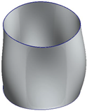
| 0 Hz | 98 Hz | 110 Hz | 112 Hz |
  | 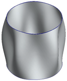  | 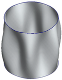  | 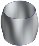  |
| 139 Hz | 165 Hz | 179 Hz | 202 Hz |
  |   | 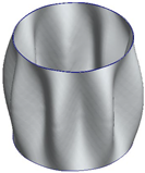  | 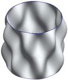 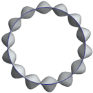 |
 |  |  |
 |  |  |
Disclaimer/Publisher’s Note: The statements, opinions and data contained in all publications are solely those of the individual author(s) and contributor(s) and not of MDPI and/or the editor(s). MDPI and/or the editor(s) disclaim responsibility for any injury to people or property resulting from any ideas, methods, instructions or products referred to in the content. |
© 2025 by the authors. Licensee MDPI, Basel, Switzerland. This article is an open access article distributed under the terms and conditions of the Creative Commons Attribution (CC BY) license (https://creativecommons.org/licenses/by/4.0/).
Share and Cite
Sozinando, D.F.; Nziu, P.; Tchomeni, B.X.; Alugongo, A.A. Dynamic Stress Wave Response of Thin-Walled Circular Cylindrical Shell Under Thermal Effects and Axial Harmonic Compression Boundary Condition. Appl. Mech. 2025, 6, 55. https://doi.org/10.3390/applmech6030055
Sozinando DF, Nziu P, Tchomeni BX, Alugongo AA. Dynamic Stress Wave Response of Thin-Walled Circular Cylindrical Shell Under Thermal Effects and Axial Harmonic Compression Boundary Condition. Applied Mechanics. 2025; 6(3):55. https://doi.org/10.3390/applmech6030055
Chicago/Turabian StyleSozinando, Desejo Filipeson, Patrick Nziu, Bernard Xavier Tchomeni, and Alfayo Anyika Alugongo. 2025. "Dynamic Stress Wave Response of Thin-Walled Circular Cylindrical Shell Under Thermal Effects and Axial Harmonic Compression Boundary Condition" Applied Mechanics 6, no. 3: 55. https://doi.org/10.3390/applmech6030055
APA StyleSozinando, D. F., Nziu, P., Tchomeni, B. X., & Alugongo, A. A. (2025). Dynamic Stress Wave Response of Thin-Walled Circular Cylindrical Shell Under Thermal Effects and Axial Harmonic Compression Boundary Condition. Applied Mechanics, 6(3), 55. https://doi.org/10.3390/applmech6030055