Biotribological Wear Prediction of Alumina–Polymer Hip Prostheses Using Finite Element Analysis


Abstract
1. Introduction
- Wear Mechanisms and Influencing Factors
- Challenges in Wear Prediction
- Rationale for FEM Implementation
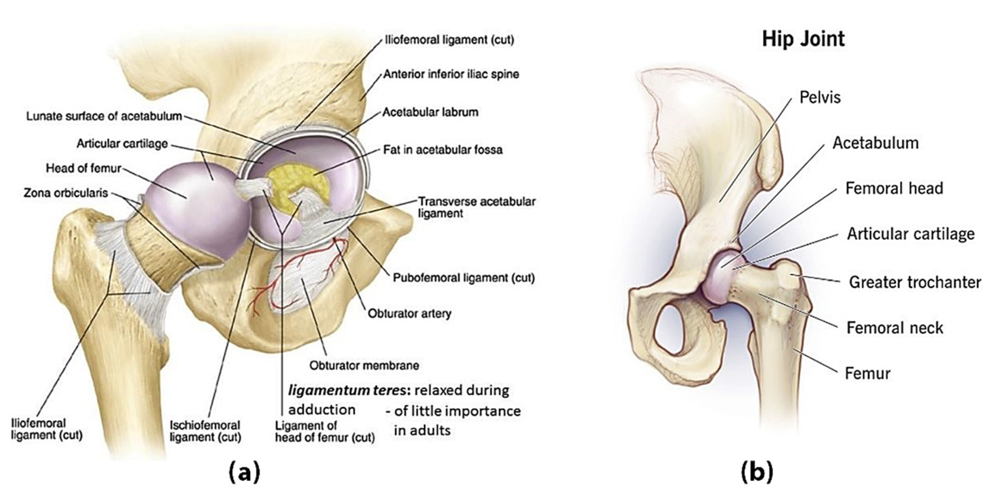
2. Basic Components of the Human Hip
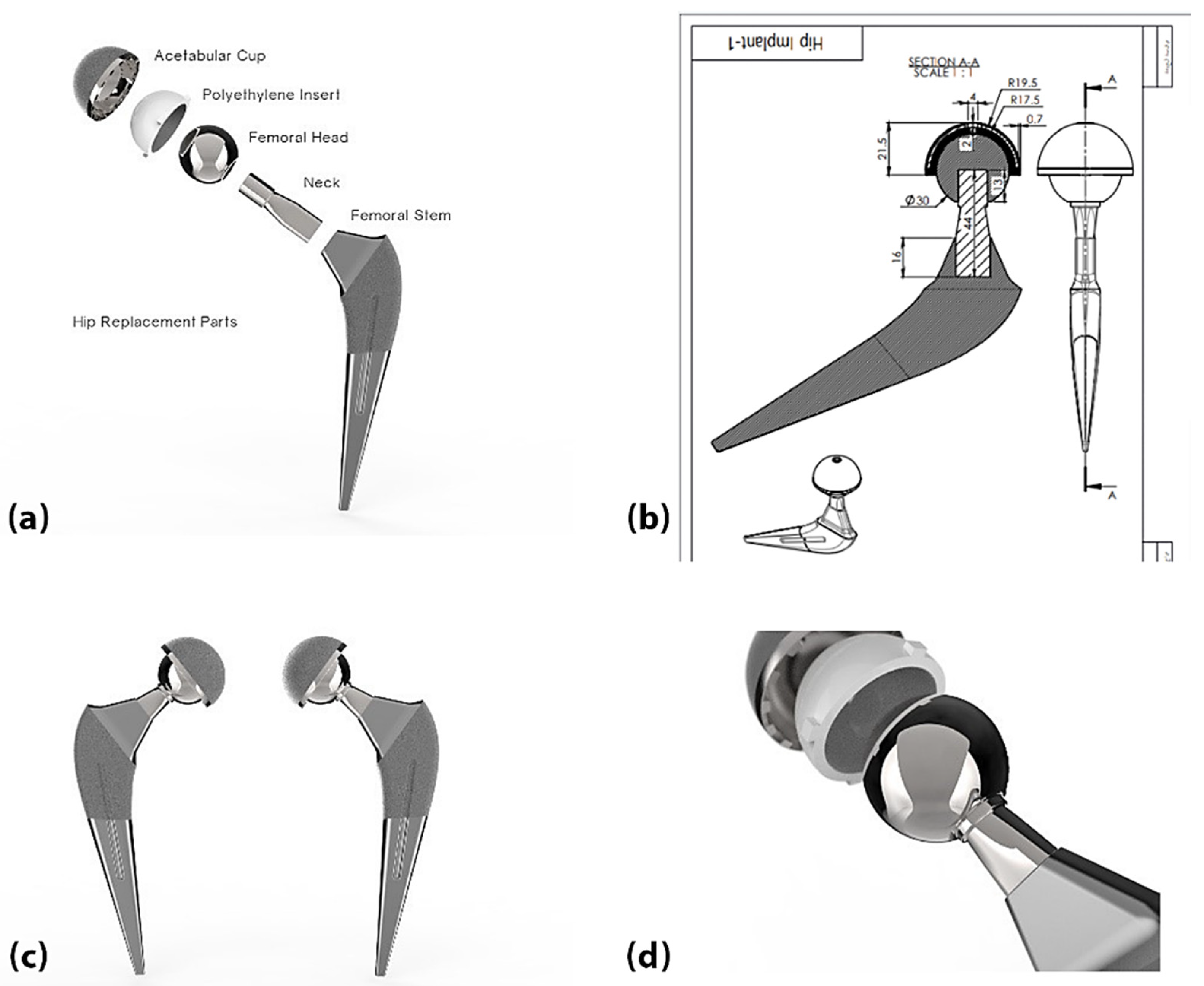
3. Hip Joint Replacement
4. Materials and Methods
- Titanium–Aluminium–Vanadium Alloys (Ti-6A1-4V):
- Alumina (AL2O3):
- Zirconia (ZrO2):
- Polyethylene (Ultra-High-Molecular-Weight Polyethylene) (UHMWPE):
- Polyetheretherketone (PEEK)
4.1. Selecting Materials for Each Element of the Components of Artificial Joints
- Acetabular cup component: Ti-6Al-4V.
- Insert component: Two types of materials were chosen for comparison: UHMWPE and PEEK.
- Femoral head component: Alumina (AL2O3).
- Stem Component: Ti-6Al-4V.
- ❖
- Alumina–UHMWPE: This combination has long been proven effective in total hip replacement (THA) surgery due to its excellent hardness, wear resistance, and biocompatibility. Further, ultra-high-molecular-weight polyethylene (UHMWPE) is a traditional bearing surface. The alumina ceramic femoral head reduces the wear of the polyethylene, reducing osteolysis and aseptic loosening risks. However, concerns remain regarding the fragility and potential for the fracturing of alumina, necessitating continued comparisons [30,31,32,33].
- ❖
- Alumina–PEEK: Polyether ether ketone (PEEK) is a high-performance thermoplastic material with good mechanical properties, an elastic modulus similar to that of cortical bone, and excellent chemical stability. When combined with alumina ceramics, PEEK may offer advantages such as reduced stress shielding, and potentially different wear behaviour compared to UHMWPE [31,32,33,34,35].
- -
- Wear rate and debris generation: How do wear debris size and particle shape differ between alumina–UHMWPE and alumina–PEEK combinations under physiological loading? These factors influence biological responses such as inflammation and osteolysis.
- -
- Long-term durability and risk of osteolysis:Does the alumina–PEEK combination reduce the incidence of implant loosening due to osteolysis compared to the alumina–UHMWPE combination, given its different wear particle properties?
- -
- Material biocompatibility and biological response:Are there different tissue reactions to the wear particles generated by this combination, which could affect implant biocompatibility?
- -
- Mechanical stability and fracture risk:
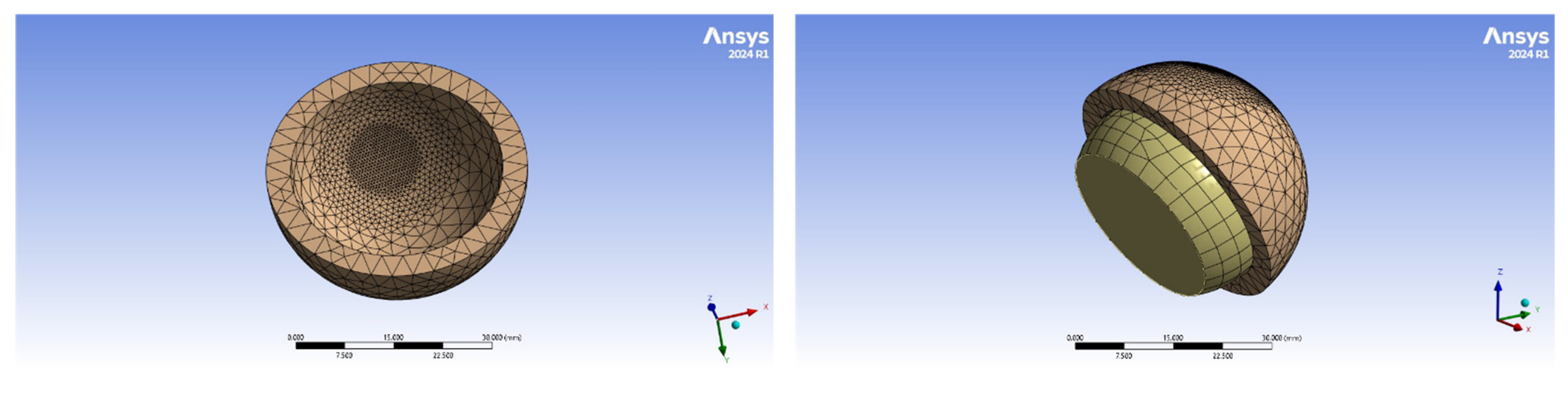
4.2. Finite Element Model Geometry
4.3. Wear in the Artificial Hip Joint
4.4. Finite Element Implementation
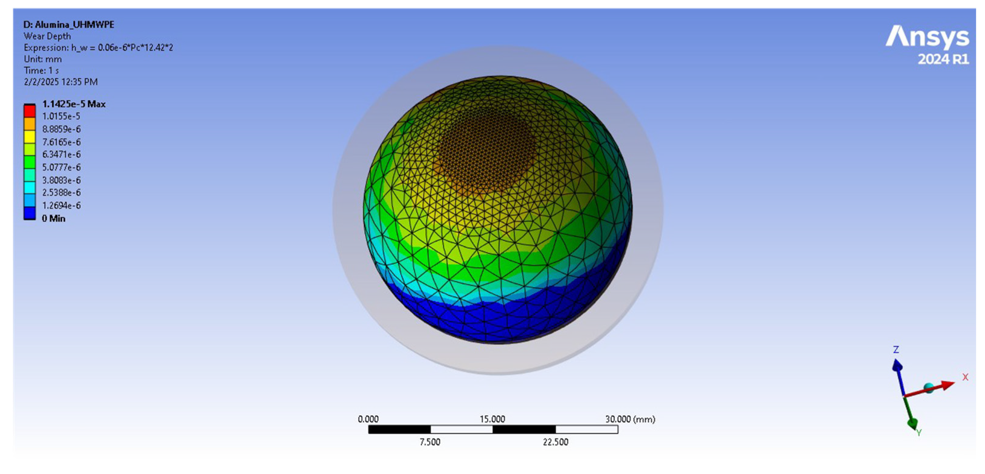
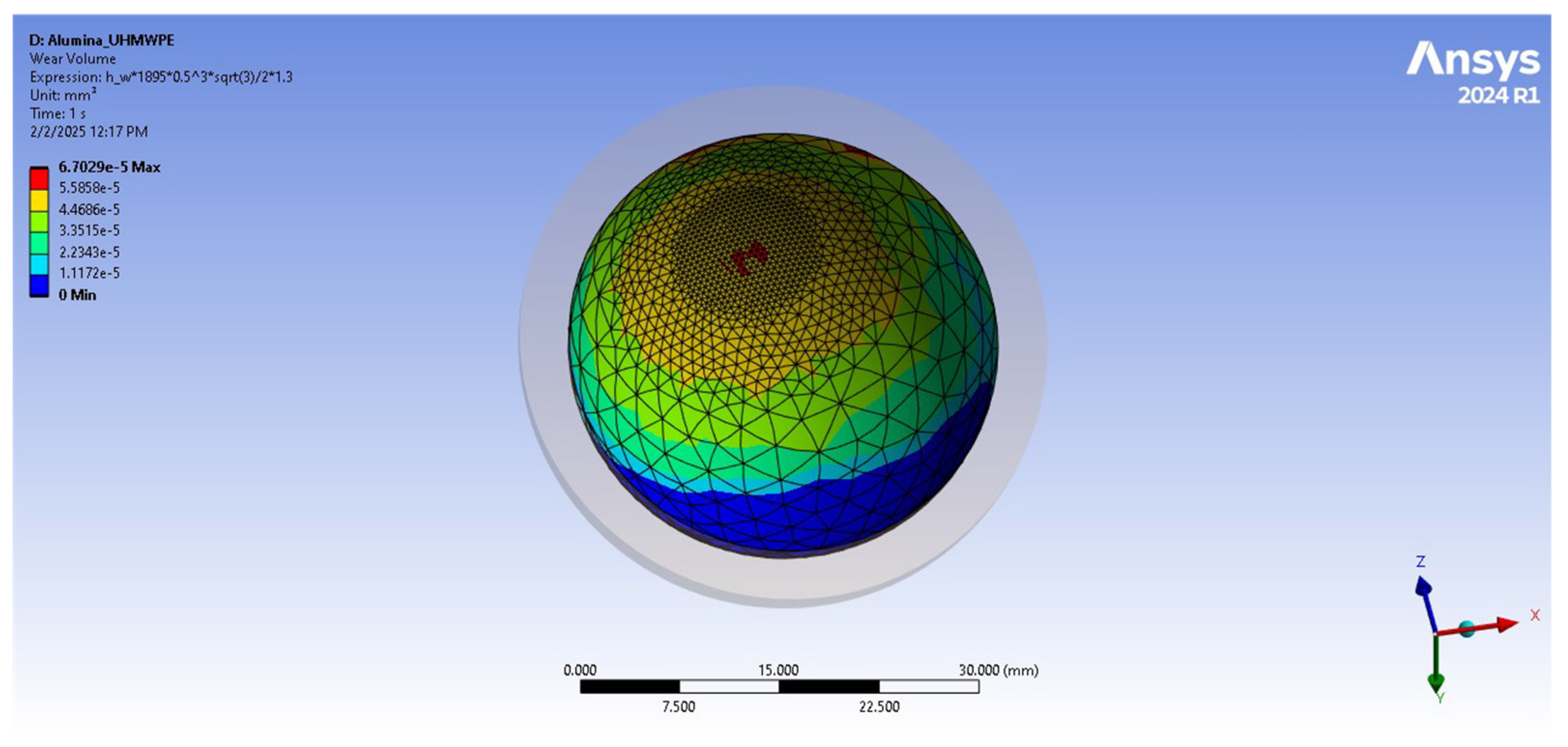
4.5. Wear Analysis and Calculation in ANSYS
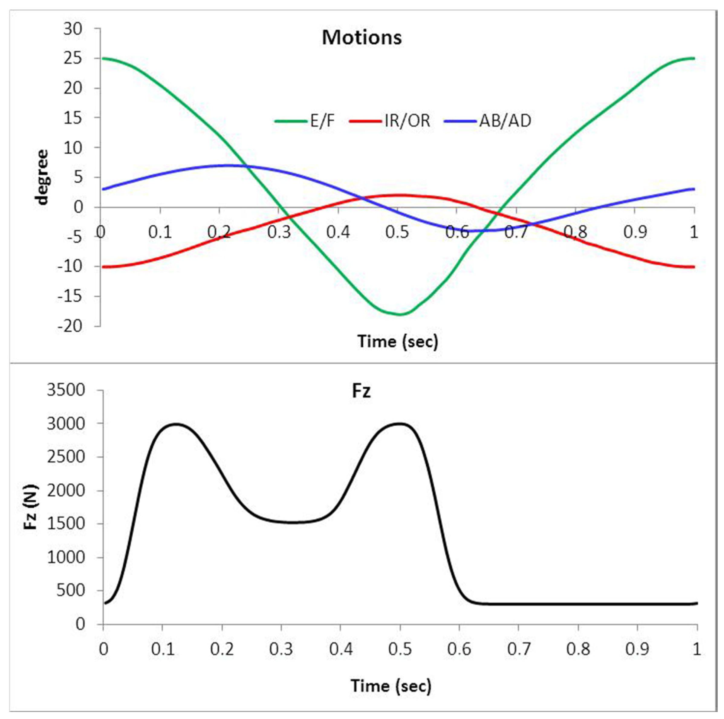
4.6. Gait Loading
- Vertical forces ranging from 300 N to 2500 N.
- Anterior–posterior shear forces up to 300 N.
- Flexion–extension moments reaching 15 N·m.
4.7. Sensitivity Analysis
4.8. Statistical Study
5. Results
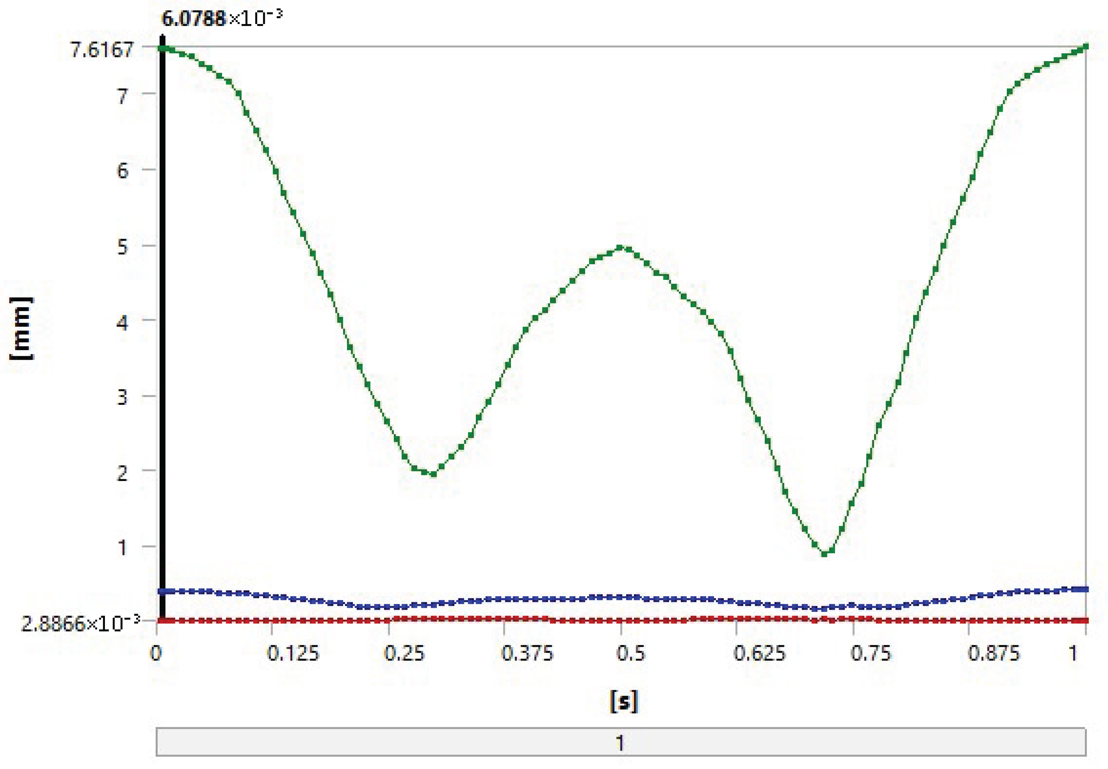
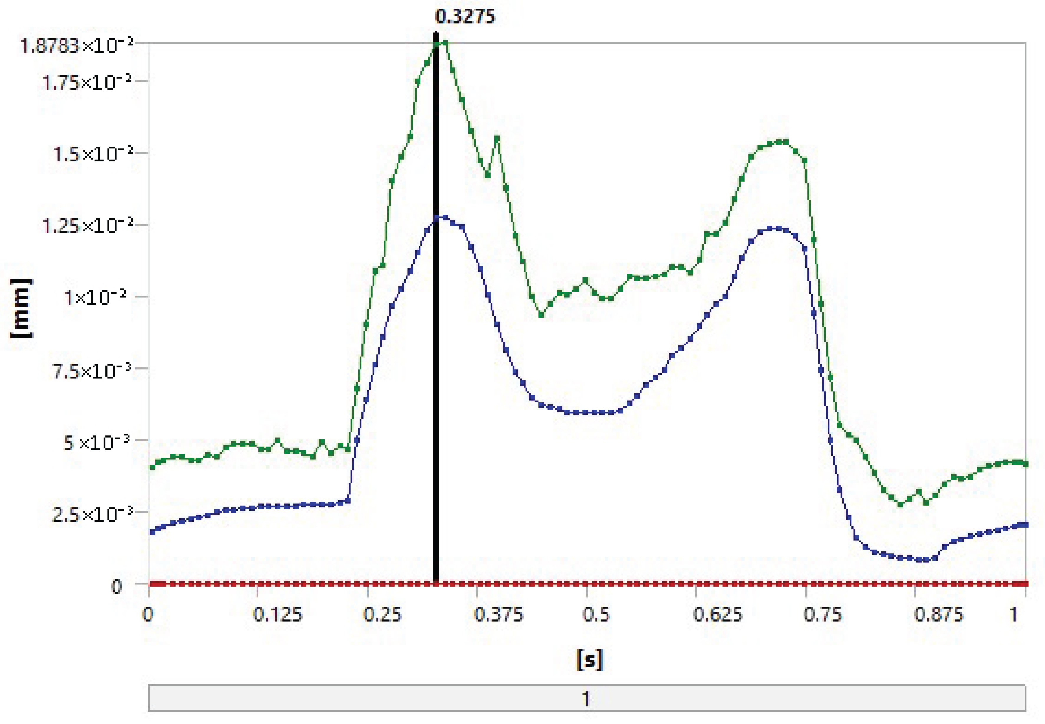
5.1. FEA
- Loading and distribution: The same loading conditions were imposed on both combinations, resulting in similar stress distributions, which promotes the occurrence of similar deformation values.
- Geometric properties: The thicknesses of the UHMWPE and PEEK parts were equal in the model, which could lead to equal deformations under the same stresses.
- Contact materials: Alumina is a very hard and strong material and can significantly influence the properties of both combinations. This results in similar deformation and contact stress due to the similar performance of alumina in both combinations.
5.2. The Statistical Study
- (Alumina–UHMWPE–UHMWPE) combination: Total score = 27.60.
- 2.
- (Alumina–PEEK) combination: Total score = 35.85.
6. Discussion
7. Conclusions
Author Contributions
Funding
Institutional Review Board Statement
Informed Consent Statement
Data Availability Statement
Acknowledgments
Conflicts of Interest
References
- Trentadue, B.; Ceddia, M.; Callea, C. Design and optimization of an artificial hip joint by finite element analysis. Biomed. J. Sci. Tech. Res. 2023, 48, 39132–39140. [Google Scholar]
- Merola, M.; Affatato, S. Materials for hip prostheses: A review of wear and loading considerations. Materials 2019, 12, 495. [Google Scholar] [CrossRef] [PubMed]
- Affatato, S. Tribological interactions of modern biomaterials used in total hip arthroplasty (THA). In Perspectives in Total Hip Arthroplasty; Elsevier: Amsterdam, The Netherlands, 2014; pp. 99–116. [Google Scholar]
- Di Puccio, F.; Mattei, L. Biotribology of artificial hip joints. World J. Orthop. 2015, 6, 77–94. [Google Scholar] [CrossRef]
- Zhang, G.; Li, J.; Li, J.; Zhou, X.; Xie, J.; Wang, A. Selective Laser Melting Molding of Individualized Femur Implant: Design, Process, Optimization. J. Bionic Eng. 2021, 18, 128–137. [Google Scholar] [CrossRef]
- Giannetti, F.A. Finite element modelling to predict wear in joint replacements. J. Mech. Behav. Biomed. Mater. 2020, 110, 103942. [Google Scholar]
- Nithyaprakash, R.; Shankar, S.; Uddin, M.S. Computational wear assessment of hard-on-hard hip implants subject to physically demanding tasks. Med. Biol. Eng. Comput. 2018, 56, 899–910. [Google Scholar] [CrossRef]
- Shankar, S.; Nithyaprakash, R. Predicting the wear of soft-on-hard bearing couples for human hip prosthesis using finite element concepts. J. Mech. Med. Biol. 2016, 16, 1650020. [Google Scholar] [CrossRef]
- Soemardi, T.P.; Suwandi, A.; Badri, C.; Ibrahim, A.S.; Wijaya, S.K.; Siregar, J.P. Development of total hip joint replacement prostheses made by local material: An introduction. In Proceedings of the 1st International Conference on Automotive, Manufacturing, and Mechanical Engineering (IC-AMME 2018), Kuta, Indonesia, 26–28 September 2018; E3S Web of Conferences. Volume 130, p. 01002. [Google Scholar]
- Jangid, V.; Singh, A.K.; Mishra, A. Wear simulation of artificial hip joints: Effect of materials. Mater. Today Proc. 2019, 18, 3867–3875. [Google Scholar] [CrossRef]
- Abdul Samad, M. Recent advances in UHMWPE/UHMWPE nanocomposite/UHMWPE hybrid nanocomposite polymer coatings for tribological applications: A comprehensive review. Polymers 2021, 13, 608. [Google Scholar] [CrossRef]
- Macuvele, D.L.P.; Nones, J.; Matsinhe, J.V.; Lima, M.M.; Soares, C.; Fiori, M.A.; Riella, H.G. Advances in ultra-high molecular weight polyethylene/hydroxyapatite composites for biomedical applications: A brief review. Mater. Sci. Eng. C 2017, 76, 1248–1262. [Google Scholar] [CrossRef]
- Gowland, N.J. The Wear and Biological Activity of Antioxidant UHMWPE for Use in Total Hip Replacements. Ph.D. Thesis, University of Leeds, Leeds, UK, 2014. [Google Scholar]
- Affatato, S.; Brando, D. Introduction to wear phenomena of orthopedic implants. In Wear of Orthopedic Implants and Artificial Joints; Woodhead Publishing: Cambridge, UK, 2013; pp. 3–26. [Google Scholar]
- Pierce, T.; Anderson, J.; Roberts, L. Clinical Outcomes of PEEK in Hip Implants: A Systematic Review. J. Biomed. Mater. Res. Part A 2022, 110, 1234–1245. [Google Scholar]
- Smith, A.; Jones, R. Wear Behavior of UHMWPE and PEEK in Artificial Joint Applications. Mater. Sci. Eng. C 2021, 118, 124565. [Google Scholar]
- Khan, M.; Müller, S.; Schneider, J. Comparative Analysis of Wear Rates: UHMWPE vs. PEEK. Int. Orthop. 2020, 44, 2105–2113. [Google Scholar]
- Liu, B.; Hua, J.; Cheng, C.K. Biomechanics of the hip. In Frontiers in Orthopedic Biomechanics; Springer: Singapore, 2020; pp. 169–188. [Google Scholar]
- Molini, L.; Precerutti, M.; Gervasio, A.; Draghi, F.; Bianchi, S. Hip: Anatomy and US technique. J. Ultrasound 2011, 14, 99–108. [Google Scholar] [CrossRef] [PubMed]
- Gold, M.; Munjal, A.; Varacallo, M. Anatomy, Bony Pelvis and Lower Limb, Hip Joint; StatPearls: St. Petersburg, FL, USA, 2017. [Google Scholar]
- Jahani, F. Modelling of Dynamic Edge Loading in Total Hip Replacements with Ceramic on Polyethylene Bearings. Ph.D. Thesis, University of Leeds, Leeds, UK, 2017. [Google Scholar]
- Jamari, J.; Ammarullah, M.I.; Santoso, G.; Sugiharto, S.; Supriyono, T.; Permana, M.S.; Winarni, T.I.; van der Heide, E. Adopted walking condition for computational simulation approach on bearing of hip joint prosthesis: Review over the past 30 years. Heliyon 2022, 8, e12050. [Google Scholar] [CrossRef] [PubMed]
- The Health Investigators. Total hip arthroplasty or hemiarthroplasty for hip fracture. N. Engl. J. Med. 2019, 381, 2199–2208. [Google Scholar] [CrossRef]
- Affatato, S.; Ruggiero, A.; Merola, M. Advanced biomaterials in hip joint arthroplasty. A review on polymer and ceramics composites as alternative bearings. Compos. Part B Eng. 2015, 83, 276–283. [Google Scholar] [CrossRef]
- Ben-Nissan, B.; Choi, A.H.; Cordingley, R. Alumina ceramics. In Bioceramics and Their Clinical Applications; Woodhead Publishing: Cambridge, UK, 2008; pp. 223–242. [Google Scholar]
- Piconi, C.; Maccauro, G. Zirconia as a ceramic biomaterial. Biomaterials 1999, 20, 1–25. [Google Scholar] [CrossRef]
- Hussain, M.; Naqvi, R.A.; Abbas, N.; Khan, S.M.; Nawaz, S.; Hussain, A.; Zahra, N.; Khalid, M.W. Ultra-high-molecular-weight-polyethylene (UHMWPE) as a promising polymer material for biomedical applications: A concise review. Polymers 2020, 12, 323. [Google Scholar] [CrossRef]
- Moharil, S.; Reche, A.; Durge, K.; Moharil, S.S. Polyetheretherketone (PEEK) as a biomaterial: An overview. Cureus 2023, 15, e44307. [Google Scholar] [CrossRef]
- Sobieraj, M.C.; Kurtz, S.M.; Rimnac, C.M. Notch sensitivity of PEEK in monotonic tension. Biomaterials 2009, 30, 6485–6494. [Google Scholar] [CrossRef] [PubMed]
- Jung, Y.L.; Kim, S.Y. Alumina-on-polyethylene bearing surfaces in total hip arthroplasty. Open Orthop. J. 2010, 4, 56–60. [Google Scholar] [PubMed]
- Kurtz, S.M. An overview of PEEK biomaterials. In PEEK Biomaterials Handbook; Elsevier: Amsterdam, The Netherlands, 2012; pp. 1–7. [Google Scholar]
- Goodman, S.B. Wear particles, periprosthetic osteolysis and the immune system. Biomaterials 2007, 28, 5044–5048. [Google Scholar] [CrossRef]
- Maloney, W.J.; Smith, R.L. Periprosthetic osteolysis in total hip arthroplasty: The role of particulate wear debris. J. Bone Jt. Surg. Am. 1995, 77, 1448–1461. [Google Scholar] [CrossRef]
- Stratton-Powell, A.A.; Pasko, K.M.; Lal, S.; Brockett, C.L.; Tipper, J.L. Biologic responses to polyetheretherketone (PEEK) wear particles. In PEEK Biomaterials Handbook; Elsevier: Amsterdam, The Netherlands, 2019; pp. 367–384. [Google Scholar]
- Stratton-Powell, A.A.; Pasko, K.M.; Brockett, C.L.; Tipper, J.L. The biologic response to polyetheretherketone (PEEK) wear particles in total joint replacement: A systematic review. Clin. Orthop. Relat. Res. 2016, 474, 2394–2404. [Google Scholar] [CrossRef]
- Bian, Y.Y.; Zhou, L.; Zhou, G.; Jin, Z.M.; Xin, S.X.; Hua, Z.K.; Weng, X.S. Study on biocompatibility, tribological property and wear debris characterization of ultra-low-wear polyethylene as artificial joint materials. J. Mech. Behav. Biomed. Mater. 2018, 82, 87–94. [Google Scholar] [CrossRef]
- Nine, M.J.; Choudhury, D.; Hee, A.C.; Mootanah, R.; Osman, N.A.A. Wear debris characterization and corresponding biological response: Artificial hip and knee joints. Materials 2014, 7, 980–1016. [Google Scholar] [CrossRef]
- Couto, M.; Vasconcelos, D.P.; Sousa, D.M.; Sousa, B.; Conceição, F.; Neto, E.; Lamghari, M.; Alves, C.J. The mechanisms underlying the biological response to wear debris in periprosthetic inflammation. Front. Mater. 2020, 7, 274. [Google Scholar] [CrossRef]
- Queiroz, R.D.; Oliveira, A.; Trigo, F.; Lopes, J. A finite element method approach to compare the wear of acetabular cups in polyethylene according to their lateral tilt in relation to the coronal plane. Wear 2013, 298, 8–13. [Google Scholar] [CrossRef]
- ISO 7206-2:2011; Implants for Surgery—Partial and Total Hip Joint Prostheses—Part 2: Articulating Surfaces Made of Metallic, Ceramic and Plastics Materials. International Organization for Standardization (ISO): Geneva, Switzerland, 2011.
- Heuberger, R.; Stöck, C.; Sahin, J.; Eschbach, L. PEEK as a replacement for CoCrMo in knee prostheses: Pin-on-disc wear test of PEEK-on-polyethylene articulations. Biotribology 2021, 27, 100189. [Google Scholar] [CrossRef]
- Koh, Y.G.; Lee, J.A.; Kang, K.T. Prediction of wear on tibial inserts made of UHMWPE, PEEK, and CFR-PEEK in total knee arthroplasty using finite-element analysis. Lubricants 2019, 7, 30. [Google Scholar] [CrossRef]
- Bistolfi, A.; Giustra, F.; Bosco, F.; Sabatini, L.; Aprato, A.; Bracco, P.; Bellare, A. Ultra-high molecular weight polyethylene (UHMWPE) for hip and knee arthroplasty: The present and the future. J. Orthop. 2021, 25, 98–106. [Google Scholar] [CrossRef] [PubMed]
- Knahr, K. (Ed.) Tribology in Total Hip Arthroplasty; Springer: Berlin/Heidelberg, Germany, 2011. [Google Scholar]
- Kaivosoja, E.; Tiainen, V.M.; Takakubo, Y.; Rajchel, B.; Sobiecki, J.; Konttinen, Y.T.; Takagi, M. Materials used for hip and knee implants. In Wear of Orthopaedic Implants and Artificial Joints; Woodhead Publishing: Cambridge, UK, 2013; pp. 178–218. [Google Scholar]
- Urban, J.A.; Garvin, K.L.; Boese, C.K.; Bryson, L.; Pedersen, D.R.; Callaghan, J.J.; Miller, R.K. Ceramic-on-polyethylene bearing surfaces in total hip arthroplasty: Seventeen to twenty-one-year results. J. Bone Jt. Surg. Am. 2001, 83, 1688–1694. [Google Scholar] [CrossRef] [PubMed]
- Mattei, L.; Di Puccio, F.; Ciulli, E.; Pauschitz, A. Experimental investigation on wear map evolution of ceramic-on-UHMWPE hip prosthesis. Tribol. Int. 2020, 143, 106068. [Google Scholar] [CrossRef]
- Barreto, S.; Folgado, J.; Fernandes, P.R.; Monteiro, J. The influence of the pelvic bone on the computational results of the acetabular component of a total hip prosthesis. J. Biomech. Eng. 2010, 107, 054503. [Google Scholar] [CrossRef]


| Material Properties | AL2O3 | Ti-6Al-4V | UHMWPE | PEEK |
|---|---|---|---|---|
| Density (kg/m3) | 3980 | 4500 | 936 | 1300 |
| Poisson’s ratio | 0.23 | 0.32 | 0.46 | 0.3 |
| Young’s modulus (GPa) | 370 | 110 | 0.5–0.8 | 3.6 |
| Yield strength (MPa) | 15.4 | 900 | 17 | 100 |
| Ultimate strength tensile (MPa) | 240 | 900 | 39–48 | 139 |
| Material Combination | Wear Coefficient [mm3/N·m] | Reference |
|---|---|---|
| Alumina–UHMWPE | 1.32 × 10⁻⁶ | [8] |
| Alumina–PEEK | 0.06 × 10⁻⁶ | [42] |
| Category | Parameter | Value | Source |
|---|---|---|---|
| Geometry | Femoral head diameter | 28 mm | ISO 7206-2 standards |
| Acetabular cup thickness | 6 mm (UHMWPE/PEEK) | Commercial implant dimensions | |
| Radial clearance | 0.05 mm | [8,41] | |
| Mesh | Element type | 10-node quadratic tetrahedral (SOLID187) | ANSYS best practices |
| Number of nodes/elements | 53,656 nodes/35,833 elements | Mesh convergence study | |
| Minimum element size | 0.3 mm (contact regions) | Stress gradient resolution | |
| Contact | Contact formulation | Surface-to-surface (CONTA174/TARGE170) | [8] |
| Friction coefficients | 0.07 (alumina–UHMWPE), 0.06 (alumina–PEEK) | [43] | |
| Algorithm | Augmented Lagrange | Numerical stability | |
| Solver | Load steps per gait cycle | 50 | ISO 14242-1 temporal resolution |
| Convergence tolerance | 5% (stress), 2% (contact pressure) | ANSYS default |
| Results | Alumina–PEEK | Alumina–UHMWPE |
|---|---|---|
| Total deformation [mm] | 0.38759 | 0.38755 |
| Volume [mm3] | 7.0783 | 7.0783 |
| Pressure [MPa] | 7.6656 | 7.6652 |
| Sliding distance [mm] | 12.419 | 12.411 |
| Gap [mm] | −0.14763 | −0.14765 |
| Penetration [mm] | 1.87 × 10⁻² | 1.85 × 10⁻² |
| Total wear depth [mm] | 3.15 × 10⁻² | 6.93 × 10⁻⁴ |
| Wear volume [mm3] | 8.4006 | 0.18481 |
Disclaimer/Publisher’s Note: The statements, opinions and data contained in all publications are solely those of the individual author(s) and contributor(s) and not of MDPI and/or the editor(s). MDPI and/or the editor(s) disclaim responsibility for any injury to people or property resulting from any ideas, methods, instructions or products referred to in the content. |
© 2025 by the authors. Licensee MDPI, Basel, Switzerland. This article is an open access article distributed under the terms and conditions of the Creative Commons Attribution (CC BY) license (https://creativecommons.org/licenses/by/4.0/).
Share and Cite
Darwich, M.A.; Nazha, H.M.; Ghadir, H.M.; Salamah, A. Biotribological Wear Prediction of Alumina–Polymer Hip Prostheses Using Finite Element Analysis. Appl. Mech. 2025, 6, 46. https://doi.org/10.3390/applmech6030046
Darwich MA, Nazha HM, Ghadir HM, Salamah A. Biotribological Wear Prediction of Alumina–Polymer Hip Prostheses Using Finite Element Analysis. Applied Mechanics. 2025; 6(3):46. https://doi.org/10.3390/applmech6030046
Chicago/Turabian StyleDarwich, Mhd Ayham, Hasan Mhd Nazha, Hiba Mohsen Ghadir, and Ahmad Salamah. 2025. "Biotribological Wear Prediction of Alumina–Polymer Hip Prostheses Using Finite Element Analysis" Applied Mechanics 6, no. 3: 46. https://doi.org/10.3390/applmech6030046
APA StyleDarwich, M. A., Nazha, H. M., Ghadir, H. M., & Salamah, A. (2025). Biotribological Wear Prediction of Alumina–Polymer Hip Prostheses Using Finite Element Analysis. Applied Mechanics, 6(3), 46. https://doi.org/10.3390/applmech6030046