Abstract
This paper focuses on the behavior of anchor channels in the event of fire. The contribution of this project lies in the necessity coming from the market to study the fire resistance of anchor channels more thoroughly, considering the modes of failure to which they are subjected. The aim of this paper is to transform the method based on tests into a numerical method that allows calculation of the fire resistance at any time under fire conditions, for all fire scenarios (whether it is a standard fire or using performance-based design approaches). A 3D transient thermal model was developed using ANSYS 19.1 to determine the thermal distribution of anchor channels, simulated in uncracked concrete under ISO 834-1 fire conditions. Subsequently, a design model for steel-related failure modes under fire conditions was employed. The model consists of coupling the characteristic resistances of the anchor channel at ambient temperature with temperature-based reduction factors for steel-related failure modes to obtain the calculated fire resistances. The model was compared with fire test results available in the literature, and the comparison yielded satisfactory results, confirming its reliability and accuracy in capturing the relevant phenomena under fire conditions. The results of this research show that the model presents a good candidate to replace the current method of qualification of anchor channels under fire conditions.
1. Introduction
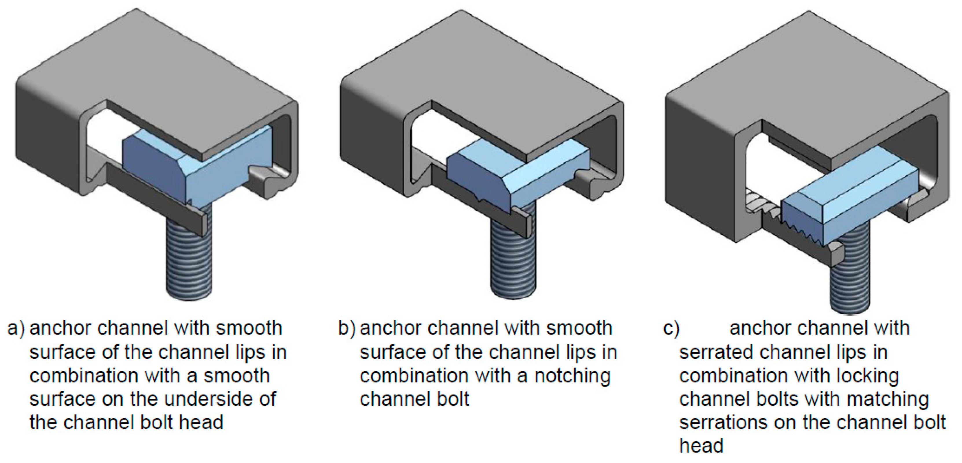
Anchor channels consist of a cold-formed or hot-rolled steel channel equipped with special anchor fittings [1]. They are cast-in-place solutions that are attached to the reinforcement in the formwork. Following the removal of the formwork, a variety of components can be attached with the help of T-shaped headed bolts. The connection between the channel and the bolt is ensured by the application of an installation torque. The load transfer mechanism relies on mechanical interlock, and the surface of the channel and the bolt can be smooth (for tension loading and shear loading perpendicular to the channel axis), serrated (for tension loading and shear loading perpendicular and parallel to the channel axis), or a combination of smooth channels and notching bolts (for tension loading and shear loading perpendicular and parallel to the channel axis); see Figure 1 [2]. The load transfer to the surrounding concrete is achieved by T- or I-shaped headed anchors that can be welded or forged to the channel back.

Figure 1.
Examples of anchor channels with different channel profiles and different channel bolt types [2].
The knowledge of this anchoring technology is still developing owing to a rapid evolution of the European guidelines for their testing and assessment. The resistance of anchor channels decreases with temperature increase, and this causes failure of the connection at high temperature. This is due to the change of material properties in fire situations. In some design cases, the consideration of the fire resistance of the connection is needed. Under these circumstances, fire design usually ends up being the governing design case. In Europe, anchor channels must undergo specific fire tests to justify the assessment of their resistance to fire.
Evaluation and test conditions of anchor channels can be carried out in accordance with EAD 330008-04-0601 [2] and their design in accordance with EN 1992-4 [3] complemented with EOTA TR 047 [4]. Anchor channels loaded in tension can have different failure modes, and the assessment for each mode is made by tests or calculations. Steel-related failure modes can manifest at any part of the steel-to-steel connections of the anchor channel (anchor, anchor/channel back, bending of channel, bending of channel lips, bolt), as well as concrete-related failure modes (breakout or blow-out in tension). Under fire conditions, concrete cone breakout can be calculated, and concrete blow-out is omitted due to the forces being taken over by the reinforcement in the concrete member. However, steel-related failure modes have to be tested, and the prediction of which steel-related failure mode will govern is difficult. Fire tests are regarded as relatively expensive, and the extrapolation of the test results to untested channel and bolt sizes is tricky and can be questionable as it is written in EAD 330008-04-0601 [2].
In this paper, a design method for steel-related failure modes of anchor channels under fire conditions is presented. The model is based on the calculation of the temperature of all parts of the anchor channel. The thermal distribution is determined throughout the exposure to fire conditions using a finite element model. The temperature of each steel element is then used to calculate its fire resistance to steel failure.
2. Literature Review
Anchor channels can be qualified for static and quasi-static loading, seismic, fatigue, and fire conditions. If all of these situations are applicable for the design case, fire design will probably govern because of the significant decrease of strength that the anchor channel can undergo if it is directly exposed to fire conditions.
Recent advancements in the behavior of adhesive anchors [5,6,7,8,9] and post-installed reinforcing bar systems [8,9,10,11,12,13,14,15,16] under fire conditions have led to the development of suitable fire qualification methods and fire design methods in Europe [17], with a specific focus on bond and steel failure modes. The background research has focused on bond and steel failure modes, introducing rational (temperature-based) fire design methods to the field of anchors. While this type of method has been well known for two decades in the Eurocodes (i.e., for concrete [18] and steel structures [19]), anchor fire design has been limited to prescriptive methods providing either conservative values without the need for qualification testing, or test-based values. Both approaches are limited to a maximum ISO 834-1 [20] fire rating of R120 (i.e., 120 min). This limitation essentially comes from the limitation of the current model for the resistance to concrete cone failure under fire conditions. Robson et al. [21] investigated concrete-related failure modes of anchors under fire conditions. Their findings [22] are still in need of further development before employing them in the current design paradigm. For example, the behavior of anchor groups, fire exposure to several sides, and the influence of different anchor sizes and embedment depths remain uninvestigated. The European Commission has issued the Delegated Regulation (EU) 2024/1681 of March 2024, supplementing Regulation EU No. 305/2011 of the European Parliament and of the council establishing classes of performance in relation to the resistance to fire of construction products [23]. This Delegated Regulation allows for the establishment of resistance-to-fire ratings up to 360 min. Therefore, to promote the use of anchor products in construction, the development of temperature-based methods and the extension/development of fire design models capable of reaching higher fire ratings is needed.
The qualification procedure for use of anchor channels under fire conditions is based only on testing. Currently, anchor channel manufacturers have to engage expensive test programs in order to qualify their products for fire. Anchor channels are qualified for fire as complete systems, with the qualification covering all of their components (steel parts and surrounding concrete). The current qualification procedure in EAD 330008-04-0601 [2] allows for a reduced test program if certain conditions are respected. For example, tests for anchor channels made of stainless steel may be omitted if:
- (1)
- Tests with anchor channels made of carbon steel of the same size are performed, and
- (2)
- The evaluated fire resistance to steel failure for carbon steel channels is used for stainless steel channels, and
- (3)
- The dimensions of anchor channels and channel bolts are the same for carbon steel and stainless steel channels, and
- (4)
- The characteristic resistances to steel failure modes under normal ambient temperature (anchor, connection between anchor and channel back, bending of channel lips, and bolt) of stainless steel channels are equal to or greater than those for carbon steel channels.
Additionally, tests for anchor channels with the bigger anchor channel sizes in a group may be omitted if:
- (1)
- Tests with the smallest anchor channel size of the group are used for the assessment, and
- (2)
- The characteristic resistances to steel failure modes under normal ambient temperature (anchor, connection between anchor and channel back, bending of channel lips, and bolt) of bigger anchor channel sizes are equal to or greater than those for the smallest anchor channel size, and
- (3)
- Channel bolt head height and head width for the smallest anchor channel size is equal to or greater than for the bigger anchor channel sizes, and
- (4)
- Only the following failure modes in all fire tests are allowed: bolt shaft, slipping of the nut over the bolt shaft, bending of channel lips.
Also, anchor channels shall be grouped according to the following principles:
- (1)
- The profile form and its manufacturing method is constant.
- (2)
- The characteristic resistances to steed failure modes under normal ambient temperature (anchor, connection between anchor and channel back, bending of channel lips, and bolt) associated with the anchor channels and the channel bolts in the group are equal to or greater than the values associated with the smallest anchor channel in the group.
Despite these strict rules, no background information in the literature is available to justify the choices made in this version of the EAD. These rules seem to be only based on the point that bigger or stronger is better, hence the conservative (safe) transfer of performance. This argument may hold under normal ambient temperature, but at high temperature, and especially under fire conditions, bigger sections can lead to a higher diffusion of temperature, leading to a premature failure of deeper parts (for example, resistance of the connection between anchor and channel back). Furthermore, the current qualification procedure neglects the resistance to bending of the channel because the qualification procedure only prescribes tests with channel bolts installed over the anchors, without tests in the mid-span of the channel. If the manufacturer applies for testing on one anchor channel size, it is permitted according to the current qualification procedure to mix all steel-related failure modes in a single assessment.
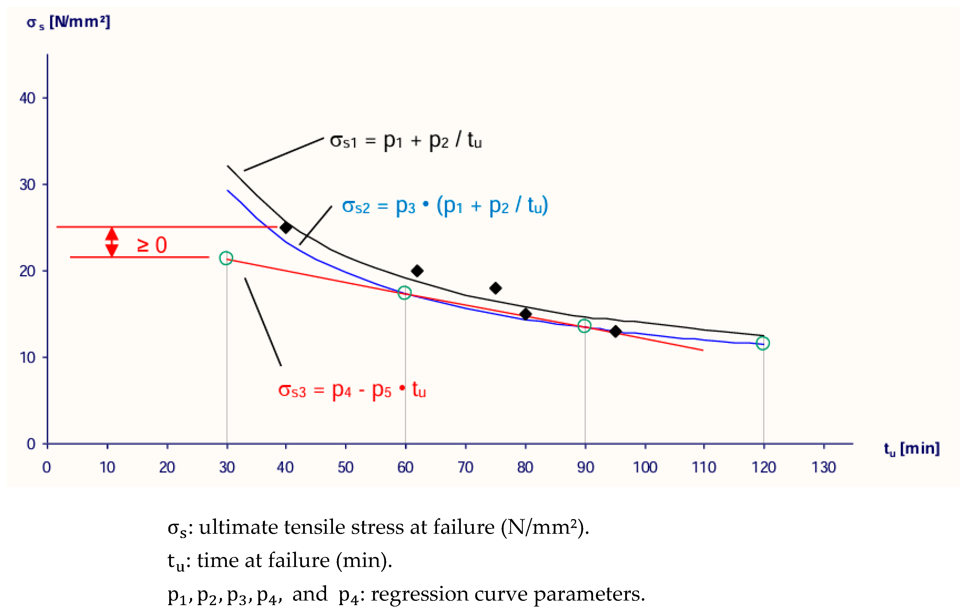
The assessment of the fire test results is based on a minimum of five tests, of which four tests must show a failure time of more than 60 min in order to presumably cover the whole fire resistance duration. This method allows for manipulation of the assessment via selective testing, where the obtained test results would favor the obtention of a relatively higher trend curve (or line) based on the potentially better statistical distribution of the results (Figure 2).
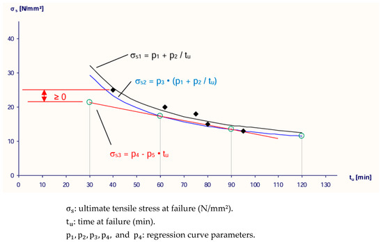
Figure 2.
Example of the determination of the characteristic steel stress based on a minimum of five fire tests [2].
For resistance to shear loading perpendicular to the longitudinal channel axis, transfer of performance is allowed in accordance with the EAD without reduction (tension equals shear resistance under fire conditions). This last exception is highly questionable, especially when tracing its origins to a note in EN 1992-4 [3], Annex D, stating: “Limited numbers of tests have indicated, that the ratio of shear strength to tensile strength increases under fire conditions above that for normal ambient temperature design. Here it is assumed that this ratio is equal to 1. This is a discrepancy to the behaviour in the cold state where the ratio is smaller than 1”. This original note is based on tests on anchors where failure of the shaft or nut was observed. In addition, recent investigations by the authors (publication in progress) have shown that the testing procedure, using a relatively big fixture for tension loading at a few centimeters from the concrete surface vs. using a metallic bar/arm for shear loading flush to the surface, may lead to more degraded thermal conditions at the nut/rod connection in both loading configurations.
This paper presents a novel approach, initially developed for steel failure of rods and reinforcing bars by Haddadi and Al-Mansouri [24], incorporated in EOTA TR 082 [17], and further adapted for the case of anchor channels, considering all steel-related failure modes based on the temperature of each part of the connection. This approach is rational (temperature-based) and presents a proper candidate for standardization. This paper is of interest to European Technical Assessment Bodies to demonstrate that the testing, evaluation, and design guidelines developed initially in EAD 330008, based on the existing knowledge at that time, are obsolete and to propose a modernization (rationalization) of fire design for the specific case of anchor channels.
3. Design Model
3.1. Thermal Simulation
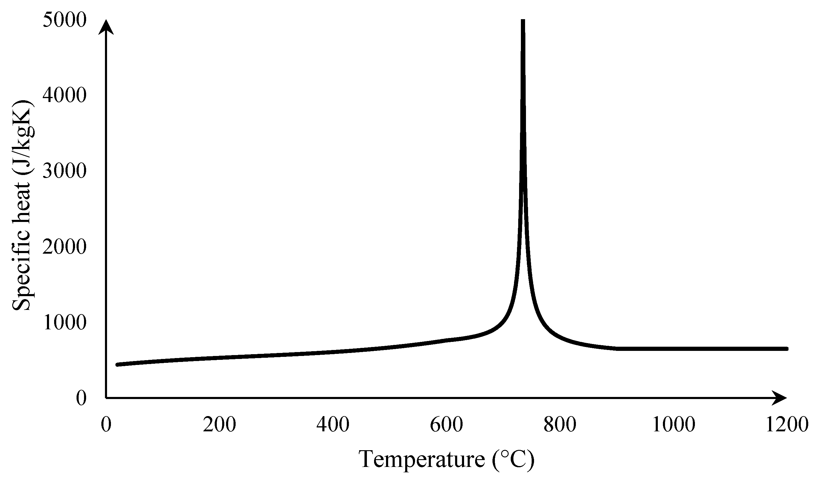
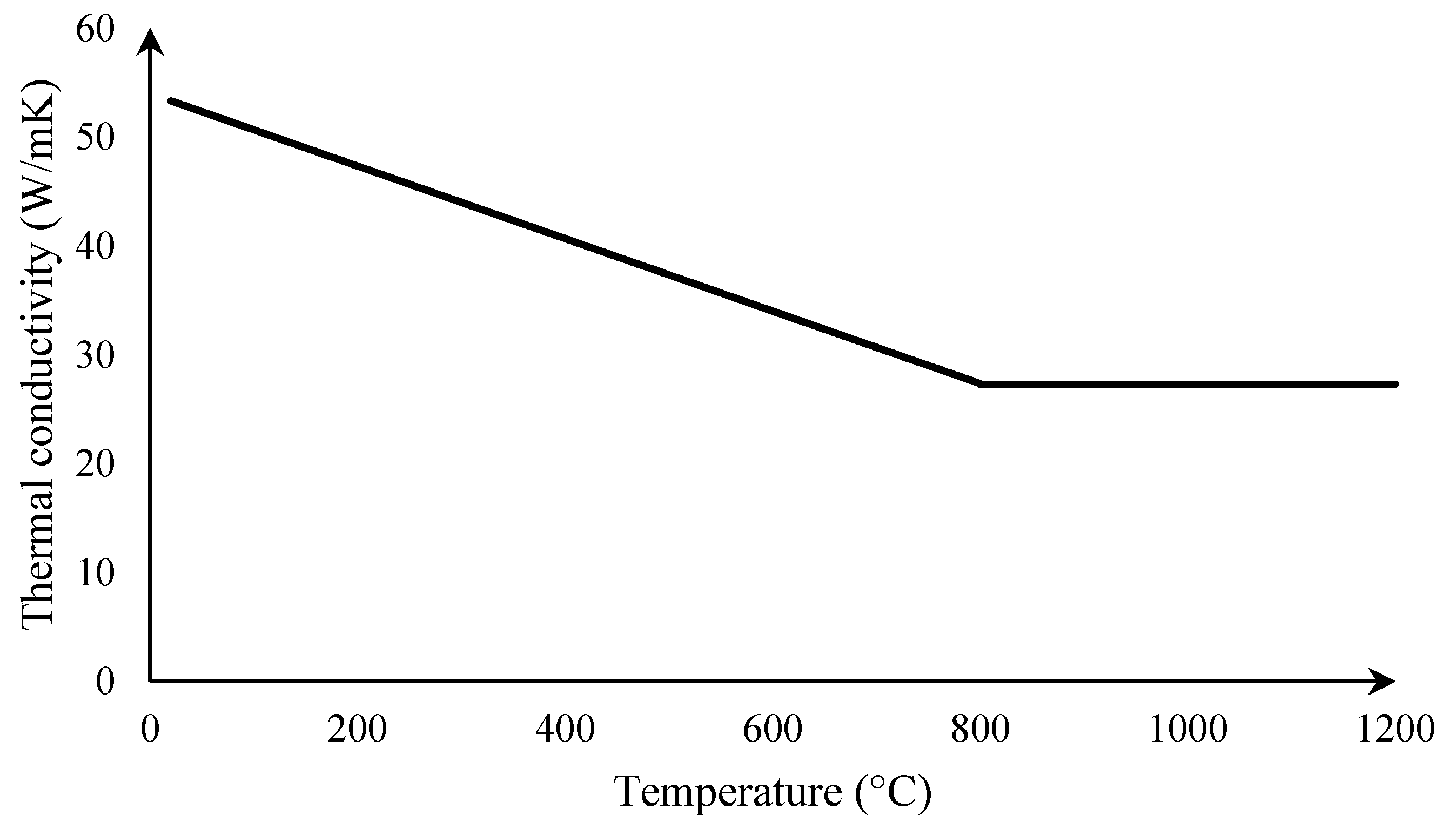
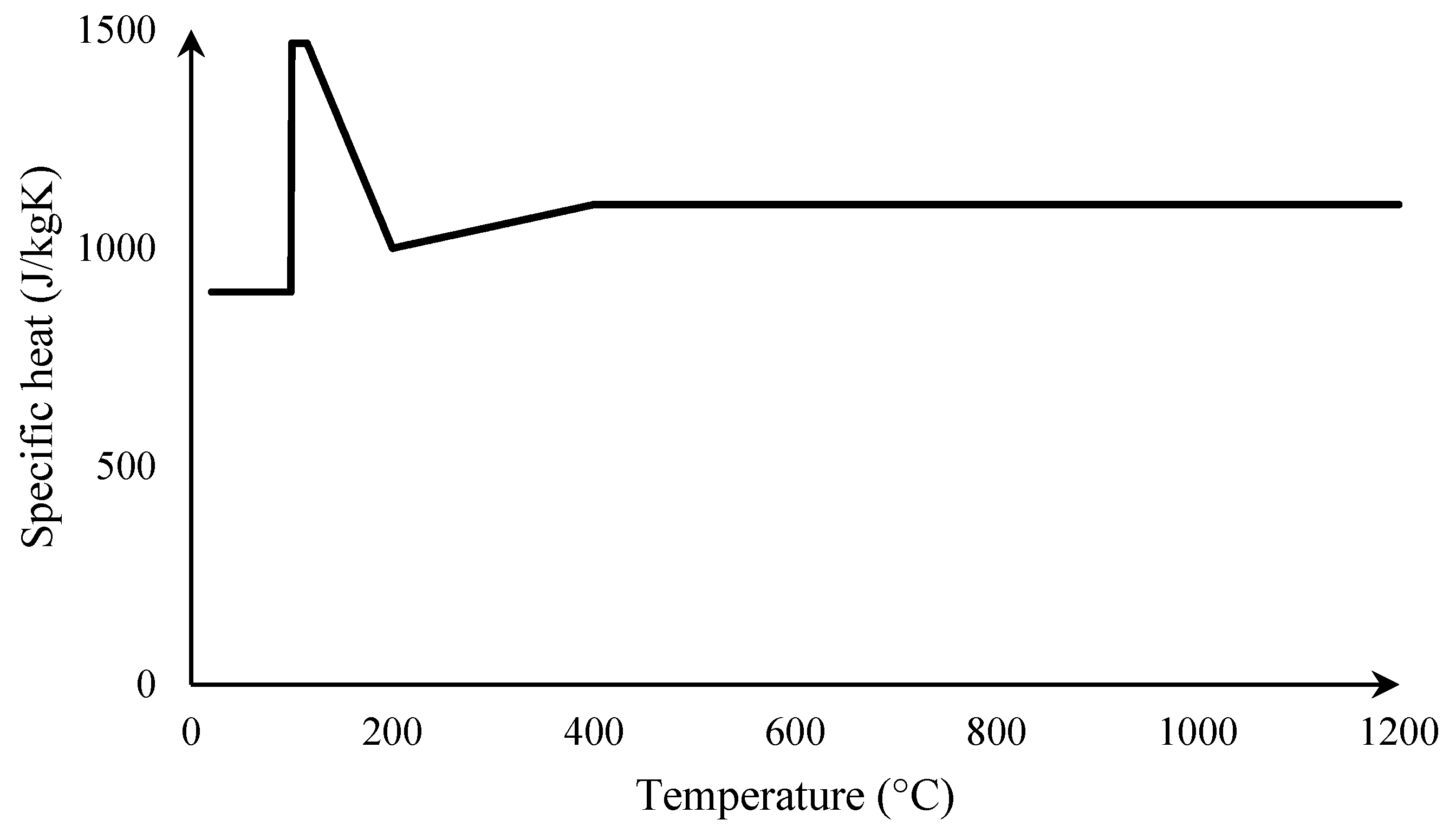
This section describes the thermal model (using ANSYS in this study) developed for the determination of the fire resistance under ISO 834-1 [20] fire conditions for anchor channels made of carbon steel in uncracked concrete. The thermal properties of carbon steel are obtained from EN 1993-1-2 [19] (Figure 3 and Figure 4).
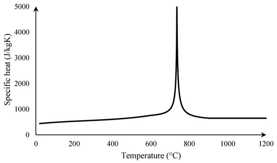
Figure 3.
Specific heat of carbon steel vs. temperature [19].
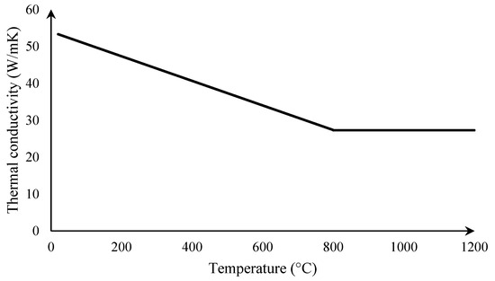
Figure 4.
Thermal conductivity of carbon steel vs. temperature [19].
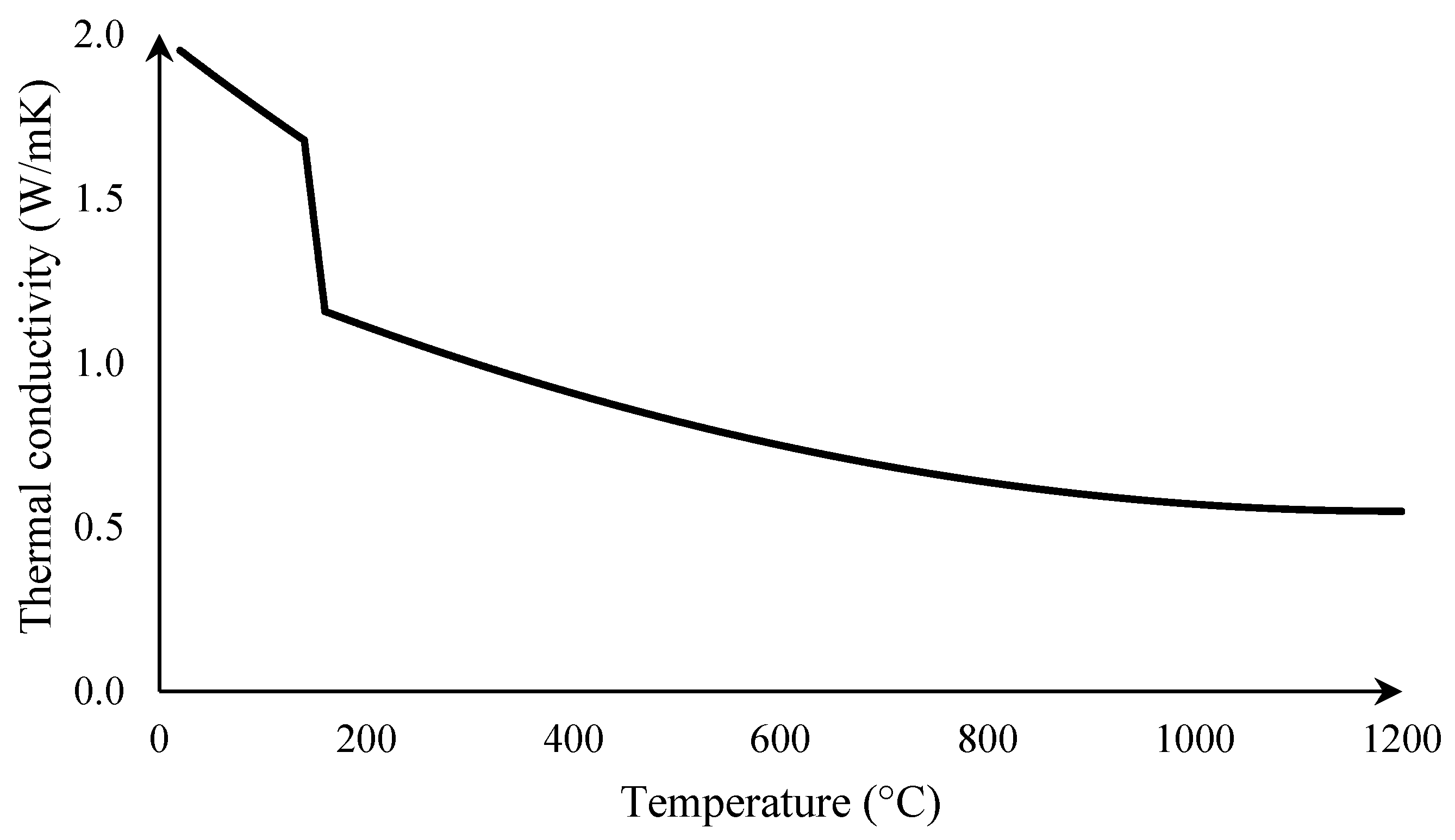
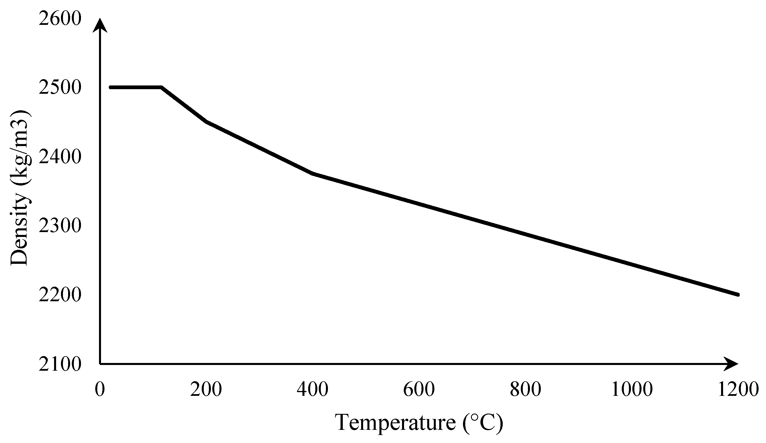
The thermal properties of concrete are obtained from EN 1992-1-2 [18] (Figure 5, Figure 6 and Figure 7). A moisture content of 1,5% was adopted for concrete based on the French practice (French National Annex) of the first generation EN 1992-1-2, which will become the harmonized approach in the second generation EN 1992-1-2.

Figure 5.
Specific heat of concrete vs. temperature [18].

Figure 6.
Thermal conductivity of concrete vs. temperature [18].

Figure 7.
Density of concrete vs. temperature [18].
In this study, the fire test results and anchor channel product in [25] are investigated. The selected case presents anchors either forged or welded to C-channels, which are cast flush in reinforced concrete elements and allow, after stripping of the formwork, the installation of matching T-bolts, which have been tested under fire conditions.
A 3D model is developed. The geometrical aspects of anchor channels do not allow 2D or 1D simplification. The geometry (dimensions) of the model depends on the complexity of the studied anchor channel product.
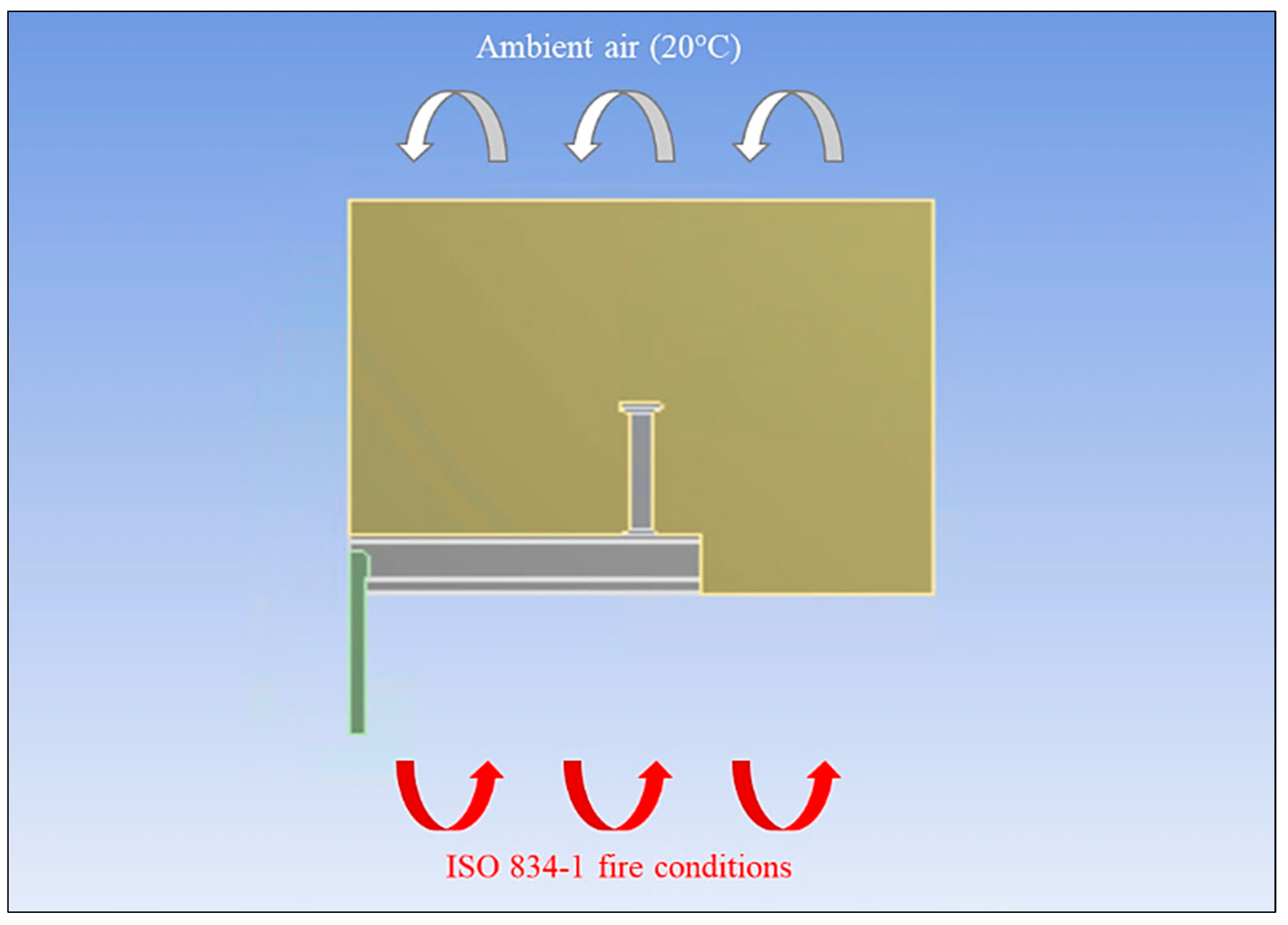
The numerical model presented in this paper is based on the following assumptions (Figure 8):

Figure 8.
Boundary conditions applied to anchor channel exposed to fire conditions.
- The lower surface of the structure is directly exposed to fire conditions.
- The upper face is exposed to ambient air (20 °C).
- The lateral part remains under adiabatic (zero heat flux).
When the system is exposed to fire conditions, heat is transferred by convection and radiation between the fire-exposed surfaces of the structure and the fire on one side, and between the unexposed surfaces of the structure and ambient air on the other side.
Furthermore, the approach involves solving the three-dimensional transient heat transfer equation to determine the temperature distribution at any specific time of exposure to fire conditions. ANSYS calculates the differential equation (Equation (1)) that governs transient heat conduction in 3D, employing an iterative solver and an implicit scheme:
The Neumann boundary conditions were used.
The heat flux exchanged by convection and radiation on the fire-exposed surface is expressed by Equation (2):
The heat flux exchanged by convection and radiation on the unexposed surface (ambient air at 20 °C) is given by Equation (3):
The lateral surface under adiabatic conditions is given by Equation (4):
- where:
- = Thermal conductivity [W/m∙K]
- = Specific heat [J/kg∙K]
- = Density [kg/m3]
- = Convective heat transfer coefficient for the fire-exposed surface [25 W/m2∙K]
- = Convective heat transfer coefficient for the surface exposed to ambient air [4 W/m2∙K]
- = Gas temperature inside the furnace as a function of time [K]
- = Ambient air temperature [293 K]
- = Solid surface temperature [K]
- = Total heat flux applied to the surface [-]
- = Surface emissivity (0.7 for c-steel and concrete) [-]
- = Stefan–Boltzmann constant [5.677∙10−8 W/m2∙K4]
3.2. Mesh Sensitivity Study
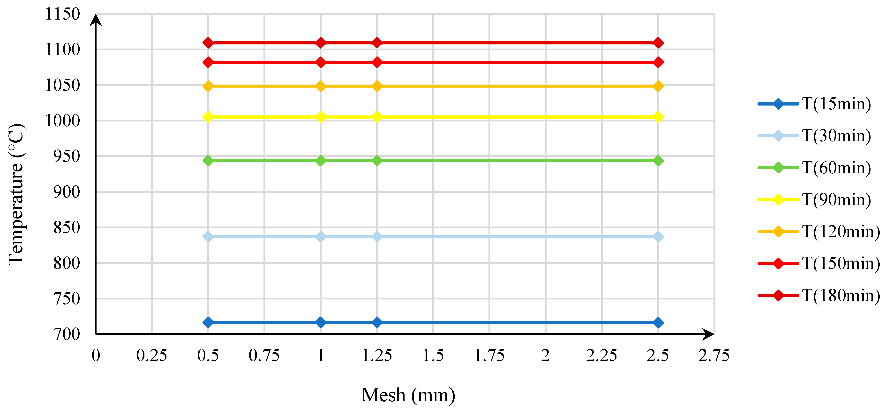
To ensure the accuracy of numerical simulations, it is necessary to find the most appropriate mesh. In this study, the mesh size was varied to assess its influence on the temperature of the bolt (the bolt being the hottest part of all components, thus considered as the determining point of view for mesh analysis) for different fire exposure times.
The initial mesh size for concrete and steel parts was based on previous studies on fixing products under fire conditions. Therefore, the size of the elements was refined (i.e., decreased), starting with the initial size chosen for mesh M (1) to M (4), as illustrated in Table 1 and Figure 9.

Table 1.
Studied steel and concrete mesh sizes.
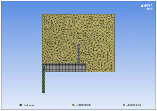
Figure 9.
Example of used mesh—representative of mesh size M (4).
Bolt temperature values for different mesh sizes were assessed for different fire exposure times from 15 to 180 min (Table 2, Figure 10).
Table 2.
Influence of spatial mesh on bolt temperature.
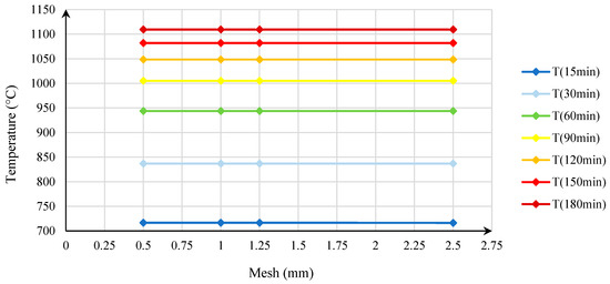
Figure 10.
Influence of spatial mesh on bolt temperature.
Based on the temperature values obtained for different mesh configurations at different fire exposure times, the influence of mesh size was deemed insignificant after 15 min of fire exposure. Furthermore, the influence of the mesh size at 15 min of fire exposure was relatively small (difference = 0.05% compared to converged value) and can be considered negligible.
3.3. Descriptive Equations of the Design Model
The characteristic tensile strength of steel under static and quasi-static tensile loading is obtained from the European Technical Assessment of the anchor channel product (ETA) and calculated in accordance with the principles laid down in EAD 330008-04-0601 [2].
Steel strength reduction factor for failure of anchors, connection between anchor and channel, channel lips, and channel bolt are presented in Table 3.
Table 3.
Steel strength reduction factor for failure of anchors, connection between anchor and channel, channel lips, and channel bolt.
- where
- θs = Temperature of the steel in the specific part of the anchor channel [°C]
- = Steel strength reduction factor for failure of anchors, connection between anchor and channel, channel lips, and channel bolt [-]
- = Specified steel yield tensile strength of specific part of the anchor channel [N/mm2]
- = Nominal steel ultimate tensile strength of specific part of the anchor channel [N/mm2]
- Fire resistance to steel failure of anchors
- where
- = Characteristic tensile steel strength of single anchor under fire conditions [kN]
- = Steel strength reduction factor in accordance with Table 3 [-]
- = Characteristic tensile steel strength of single anchor at ambient temperature [kN]
- Fire resistance to steel failure of the connection between anchor and channel
- where
- = Characteristic tensile steel strength of connection between anchor and channel under fire condition. [kN]
- = Steel strength reduction factor in accordance with Table 3 [-]
- = Characteristic tensile steel strength of connection between anchor and channel at ambient temperature [kN]
- Fire resistance to steel failure of channel lips
- where
- = Characteristic tensile steel strength of the local bending of channel under fire conditions [kN]
- = Steel strength reduction factor in accordance with Table 3 [-]
- = Characteristic tensile steel strength of the local bending of channel at ambient temperature [kN]
- Fire resistance to steel failure of channel bolt
- where
- = Characteristic tensile steel strength of channel bolt under fire conditions [kN]
- = Steel strength reduction factor in accordance with Table 3 [-]
- = Characteristic tensile steel strength of channel bolt at ambient temperature [kN]
- Fire resistance of steel failure by bending of anchor channel
- where
- = Characteristic tensile steel strength of anchor channel in case of bending failure of channel under fire conditions [kN]
- = Steel strength reduction factor in accordance with Table 4 [-]
Table 4. Steel strength reduction factor for failure by bending of anchor channel.
- = Characteristic tensile steel strength of anchor channel in case of bending failure of channel at ambient temperature [kN]
3.4. Validation of the Design Model
The goal of this section is to prove the applicability of the rational design method (temperature-based instead of fire rating-based), which has been validated for post-installed rebars and bonded anchors, and transfer this methodology to the anchor channels. In order to validate the results obtained from the developed model, tests carried out on the studied anchor channel were adopted from the literature [25] as a basis of comparison by considering the failure modes of all the components of the anchor channel product and focusing on the steel-related failure modes. The fire resistance of the anchor channel was determined using the model up to 3 h of exposure to fire conditions (fire rating of 180 min).
The characteristic resistances to steel failure at ambient temperature are illustrated in Table 5.
Table 5.
Characteristic resistances to steel failure at ambient temperature.
The fire resistance to steel failure obtained from fire tests and the corresponding fire exposure time are reported in Table 6.
Table 6.
Failure modes and fire resistance values from fire tests on anchor channel.
The reduction factor for all steel-related failure modes was then determined, as shown in detail in Table 7, for different temperatures, from 20 °C to 1200 °C.
Table 7.
Reduction factor vs. temperature for channel-related failure modes and bolt failure.
The method described in the previous equations and figures is summarized in Figure 11 for all steel-related failure modes.
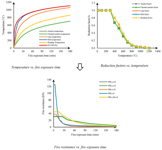
Figure 11.
Illustration of the fire design method.
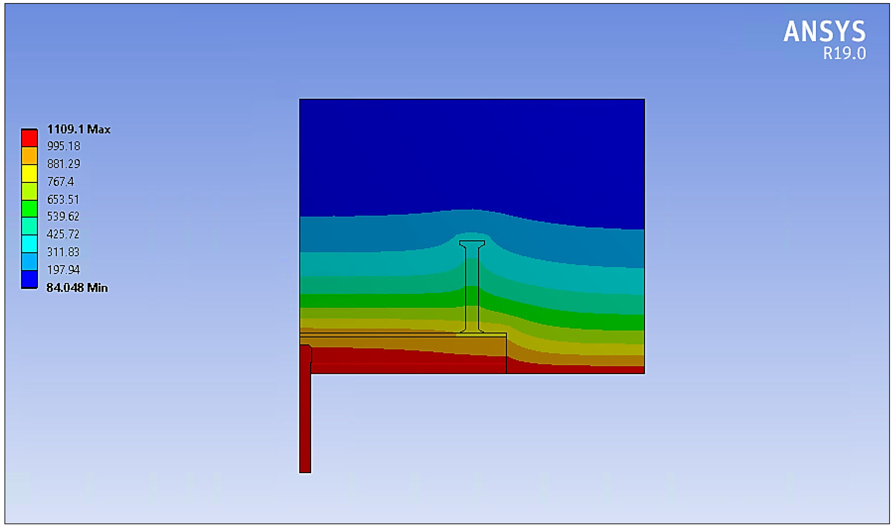
Figure 12 shows an example thermal distribution experienced by the anchor channel and its surrounding concrete at 180 min of exposure to the ISO 834-1 [20] fire scenario. The boundary conditions presented in Figure 8 demonstrate the studied problem. Fire coming from below in Figure 12 is the design case the paper addresses. The exposed surfaces of concrete and steel are not protected from the ISO 834-1 [20] fire conditions. The isotherms show a curved tendency demonstrating the steel’s capacity to create a thermal bridge towards the inner parts of the concrete element.

Figure 12.
Example of thermal distribution experienced by the anchor channel and surrounding concrete at 180 min of fire exposure.
It can be observed that although steel is a very diffusive material, not all parts of the anchor channel experience the same temperature instantaneously. A significant difference can be observed between different parts of the anchor channel (e.g., while the head of the bolt is at 1109 °C, the connection of the anchor and channel experiences a temperature around 800 °C). This is partly due to the fact that the embedded parts of the anchor channel are not exposed directly to the convective and radiative boundary conditions applied to the exposed parts (lips and bolt). The heat is diffused through conduction from the exposed parts to the embedded parts, which generates this temperature difference from the top to the bottom of the anchor channel.
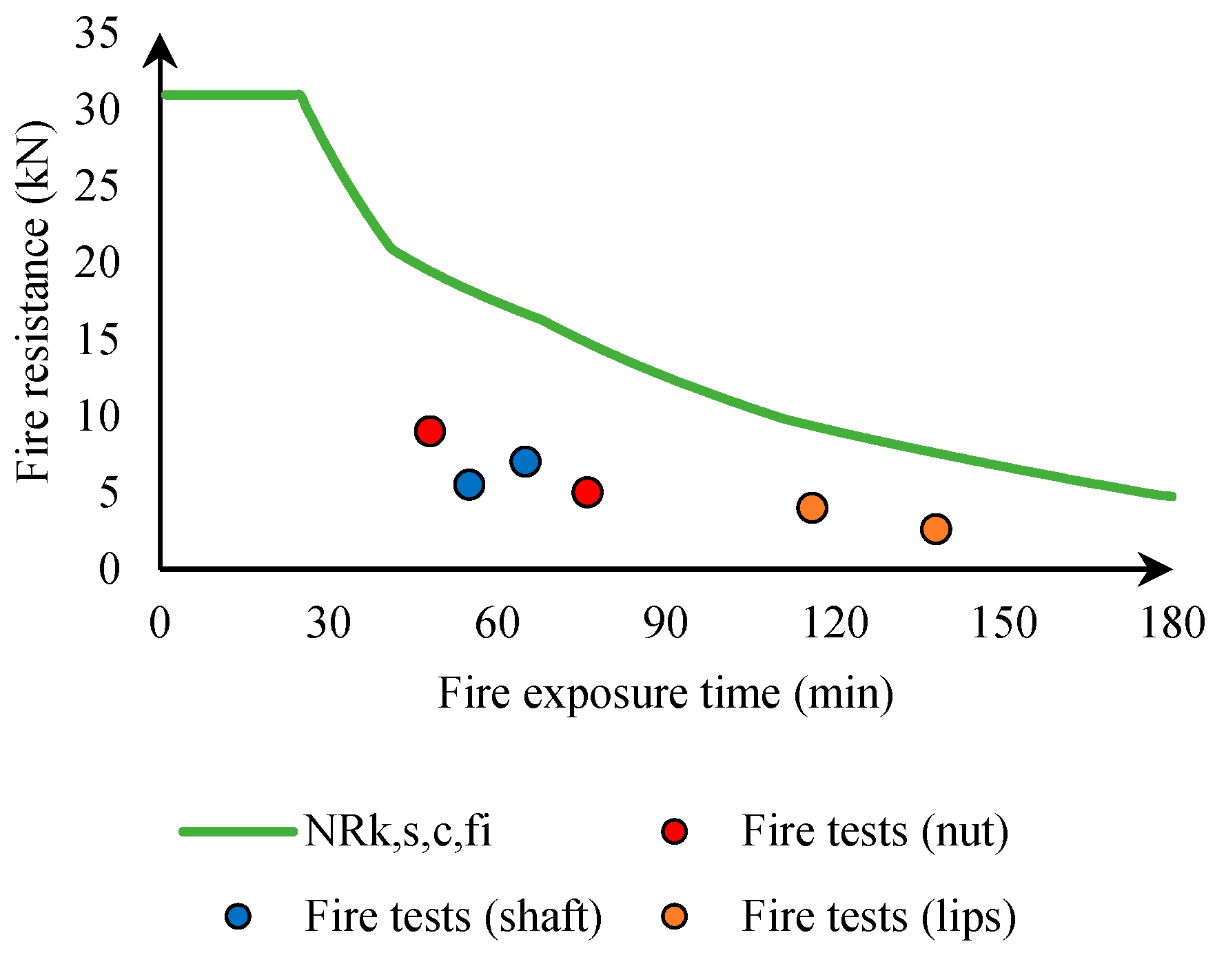
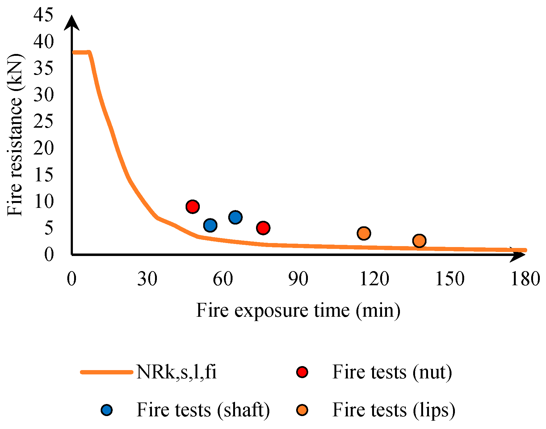
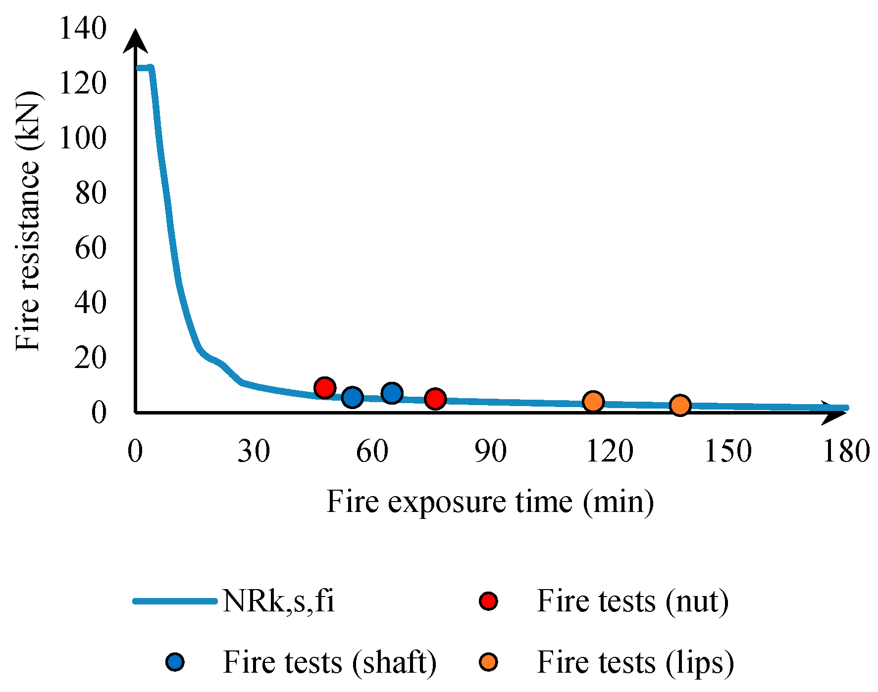
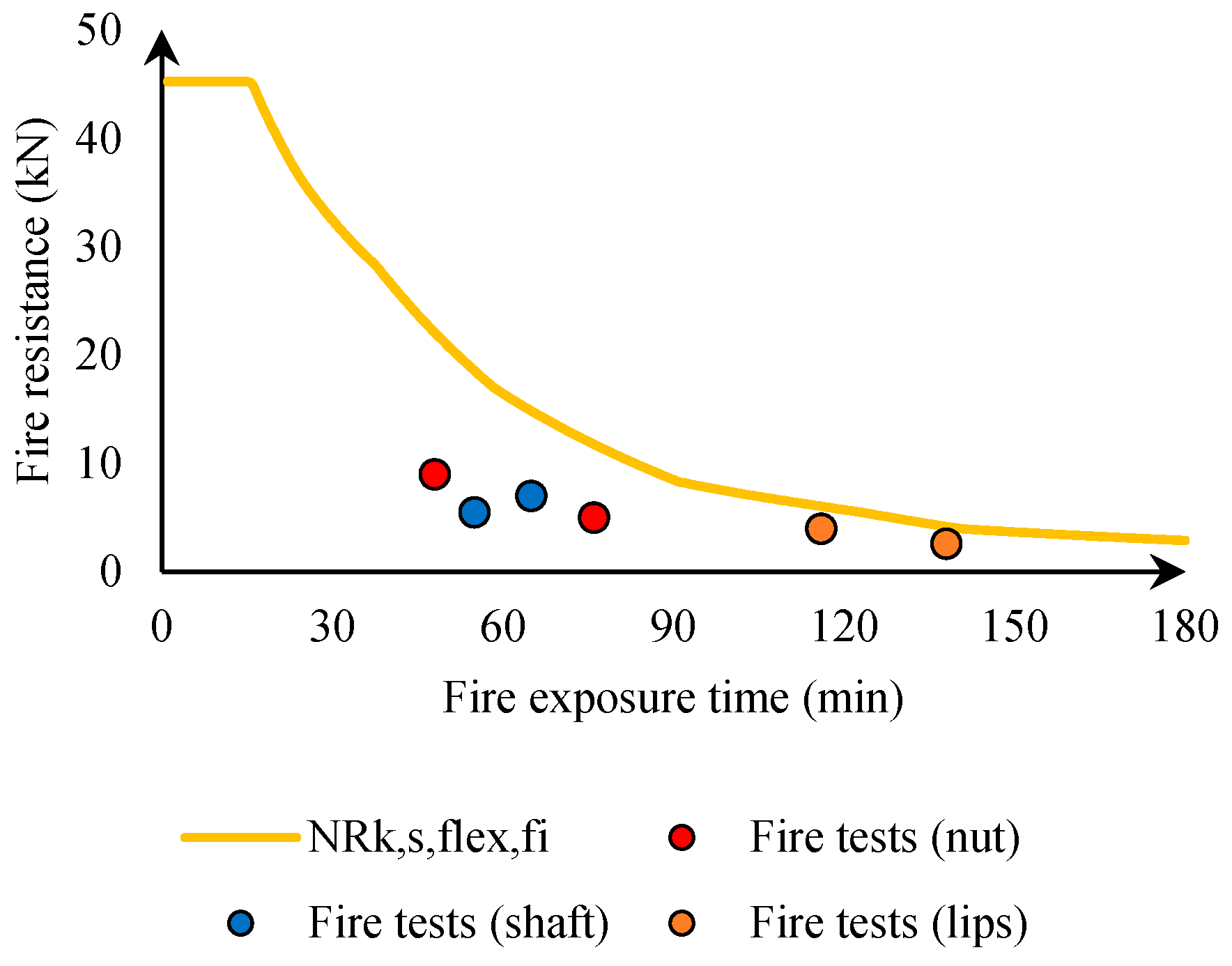
The association of temperature results from the thermal model that allowed the reduction factors to obtain the calculated fire resistance of the anchor channel (for all failure modes). Figure 13, Figure 14, Figure 15, Figure 16 and Figure 17 show the detailed calculation for each failure mode of the anchor channel vs. fire exposure time. It is clear that the model allows for the calculation of fire resistance at every minute (unlike the current method, which gives values for 30, 60, 90, and 120 min only). Some failure modes show that the calculation is above the fire test results, which is normal because their failure is not probable as they do not present the lowest resistance of all failure modes (e.g., failure of the anchor, connection between the anchor and channel, and bending). However, lip failure and bolt failure seem to be the most probable failure modes to occur under fire conditions, due to the high temperature experienced at their location and the high resistance reduction associated with this temperature. Figure 13, Figure 14, Figure 15, Figure 16 and Figure 17 show that the calculations yield values that are conservative compared to fire test results for the same failure mode obtained in testing and simulation, confirming that validation of the model for the studied anchor channel is a safe alternative to fire testing.

Figure 13.
Characteristic fire resistance to steel failure of anchors.

Figure 14.
Characteristic fire resistance to steel failure of the connection between anchor and channel.
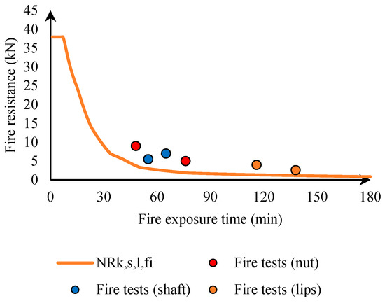
Figure 15.
Characteristic fire resistance to steel failure of channel lips.
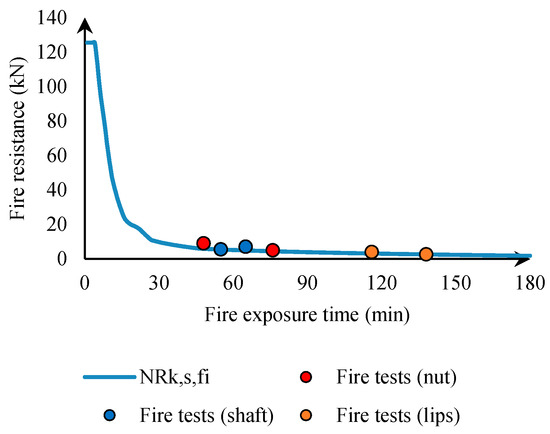
Figure 16.
Characteristic resistance to steel failure of channel bolt.
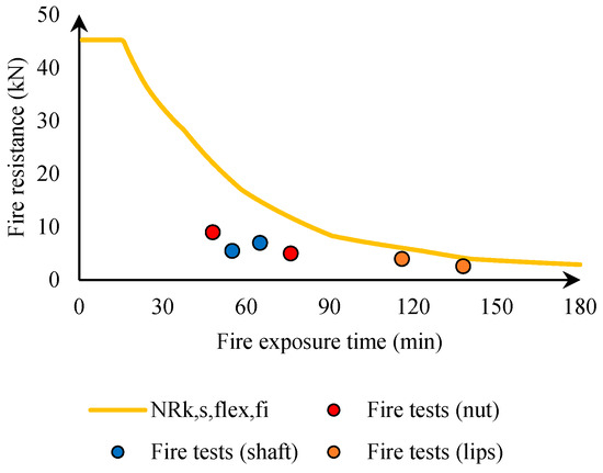
Figure 17.
Characteristic fire resistance to steel failure by exceeding the bending strength of the channel.
Figure 13, Figure 14, Figure 15, Figure 16 and Figure 17 aim to isolate the calculation for each failure mode in comparison to the fire test results. This comes in handy when the evaluators and manufacturers wonder about the choice of not conducting tests in mid-span to assess the flexural strength of the channel through fire tests (some failure modes may never show up in a fire test). This is also beneficial because it shows that, in the case of anchor channels directly exposed to fire conditions, the failure of the bolt and lips always govern and may alternate from one to the other for different fire exposure times. The level of reduction of some failure modes (i.e., bolt) compared to others (i.e., lips) shows that an error may be made when mixing all steel-related failure modes in a single evaluation (the EAD method).
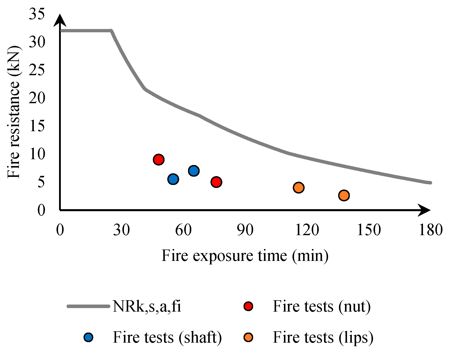
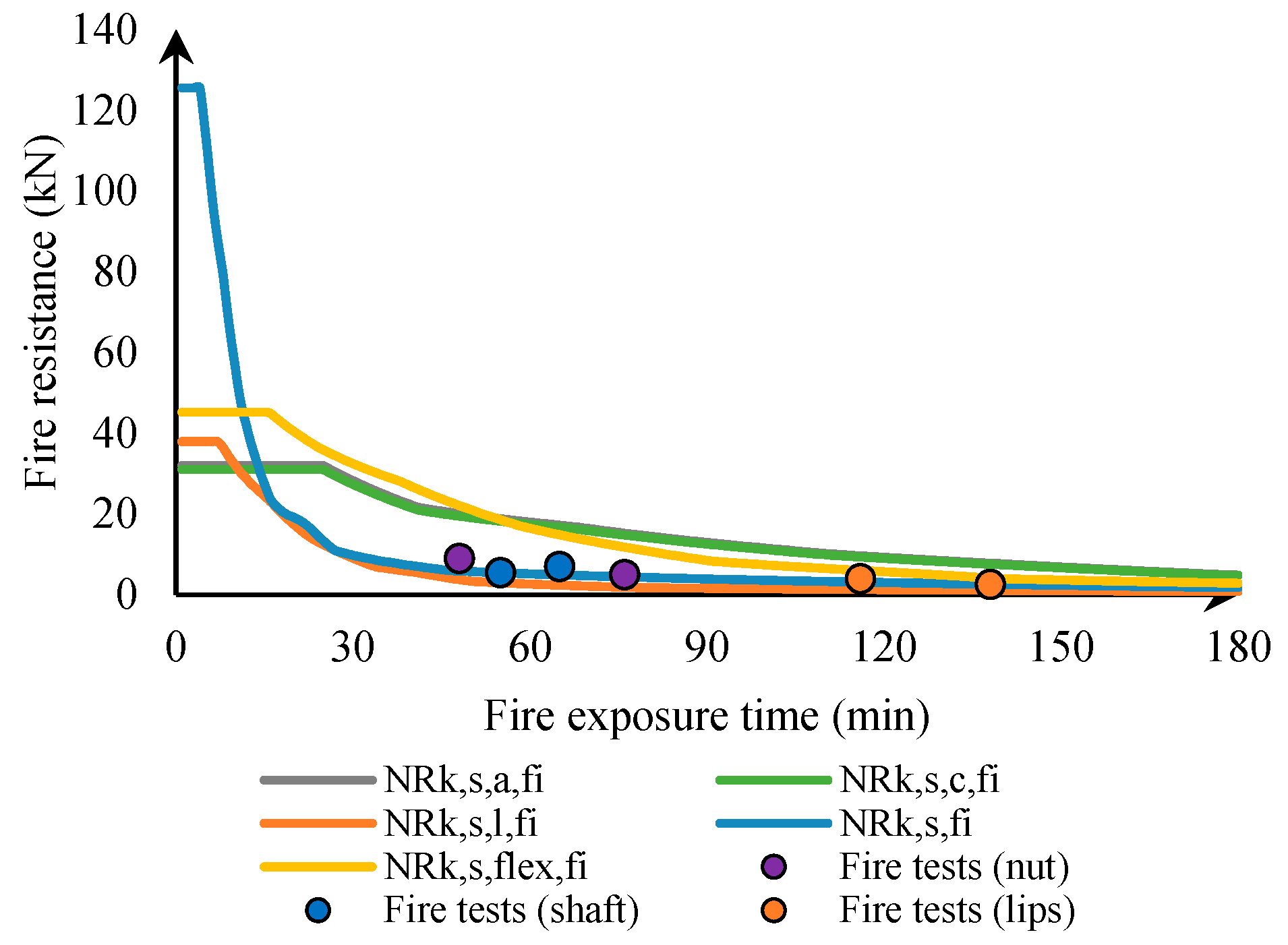
Figure 18 shows the combination of all steel-related failure modes in one graph. At ambient temperature (before exposure to fire conditions), the dominant failure mode is the connection between anchor and channel. Under fire conditions, the degradation of the resistance to lip failure is faster than that of the connection between anchor and channel, and starting from a certain fire exposure time (approximately 18 min), lip failure becomes the governing failure mode of the anchor channel. For most of the fire exposure time, a competition between lip failure and bolt failure seems to occur, although the difference between both resistances at ambient temperature is significant. This is due to the higher temperature of the bolt compared to that of the lip at the same time of exposure to fire conditions (from 150 °C to 200 °C).

Figure 18.
Summary of the different steel-related failure modes as function of fire exposure time.
The conservatism of the model was assessed against the available fire test results (real measured values with tests in a gas furnace). Table 8 shows the test results and calculated resistance for all steel-related failure modes.
Table 8.
Calculated and measured fire resistance values vs. fire exposure time.
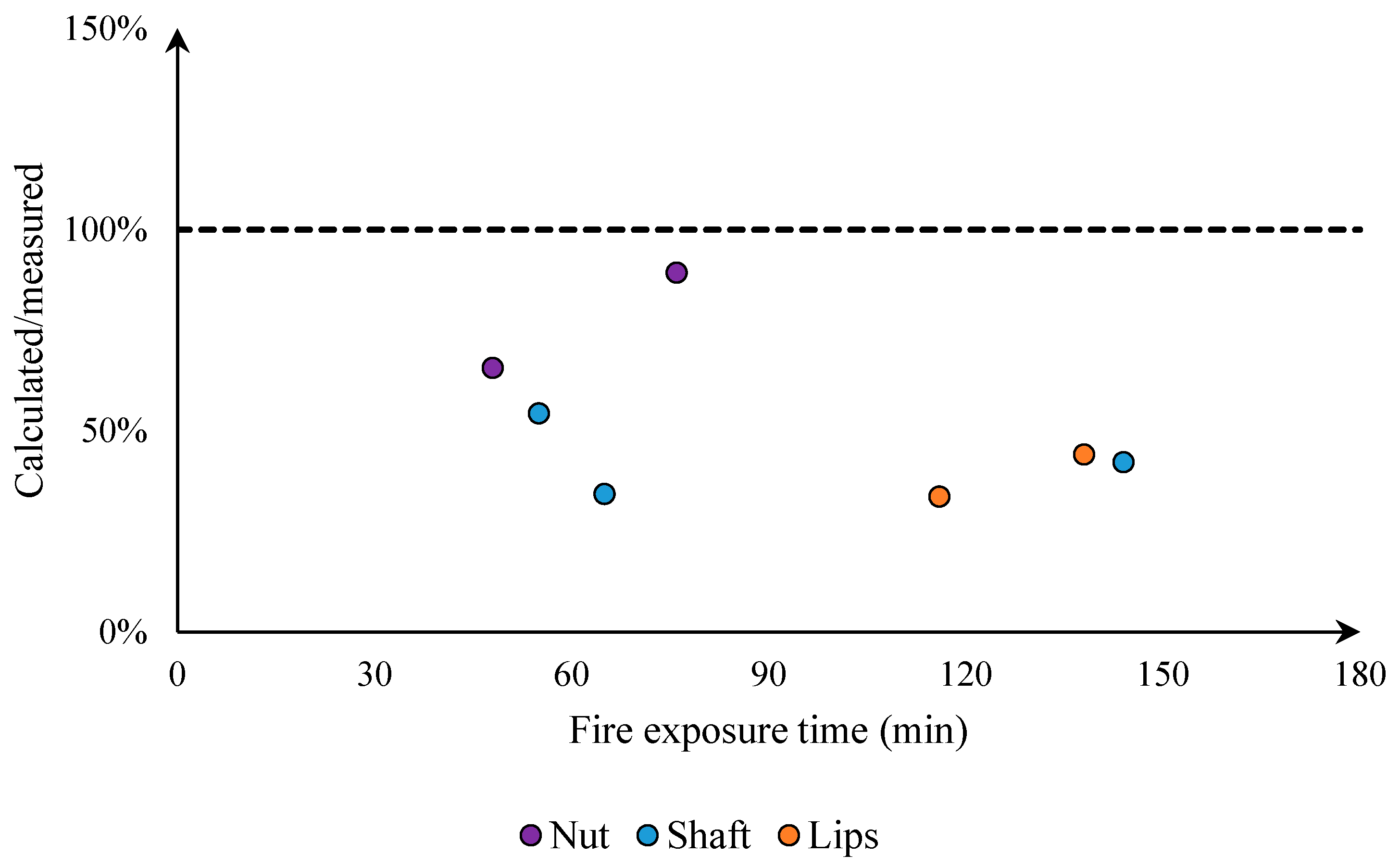
To assess the conservatism of the model, the tested to calculated ratio was assessed (Figure 19). It can be observed that the ratio is higher than 1.0, which emphasizes the conservatism of the model. Furthermore, the ratio varied between 0.34 to 0.89 for lip and bolt failure modes.

Figure 19.
Tested/calculated ratio of fire resistance vs. fire exposure time.
The conservatism of the model is justified by the following points:
- The model uses Eurocode material properties (for concrete and steel). These properties are design values (i.e., safe values) that ensure conservative results.
- The numerical model ensures perfect application of thermal boundary conditions (radiation and convection of the ISO 834-1 fire). When an anchor channel is tested in a real furnace, the applied ISO 834-1 fire scenario may be less severe than the simulated one because of the kinetics of the furnace and physical phenomena occurring in a fire test (water vaporization, actual material emissivity, limited convection in small spaces, etc.).
4. Conclusions
This paper presents the model developed for the determination of fire resistance under fire conditions for anchor channels made of steel. The design method uses numerical calculations based on finite element simulations and gives temperature profiles along the anchor channel throughout the fire exposure time. These temperatures are used to assess steel resistance as a function of fire exposure time, using temperature-based reduction factors derived from the material properties in EN 1993-1-2 [19]. It proves that the proposed model is efficient in the case of the studied anchor channel product. It is concluded that this method is a good candidate to replace the current test method and make the fire design of anchor channels more rational.
This work opens the door to further development of the fire design of these products. For example, the model can be extended to other cases of anchor channel products. Furthermore, fire protection solutions can be applied to the exposed parts to improve their fire resistance. If the resulting temperature during fire exposure of such a solution is known, the method can be validated for fire-protected anchor solutions. Another perspective use could be to investigate the behavior of anchor channels under other fire exposure scenarios (hydrocarbon fire, real fire, etc.). Finally, the developed model can be used to assess the validity of the assumptions allowing for the transfer of test results from tested to untested configurations of anchor channel and channel bolt sizes, materials, and shapes.
Author Contributions
Conceptualization, O.A.-M.; methodology, O.A.-M.; software, M.S. and O.A.-M.; validation, M.S. and O.A.-M.; formal analysis, M.S. and O.A.-M.; investigation, M.S. and O.A.-M.; resources, O.A.-M. and C.M.; data curation, C.M.; writing—original draft preparation, M.S.; writing—review and editing, O.A.-M. and C.M.; visualization, O.A.-M. and C.M.; supervision, O.A.-M.; project administration, O.A.-M.; funding acquisition, O.A.-M. All authors have read and agreed to the published version of the manuscript.
Funding
This research received funding from CAMA (Concrete and Masonry Anchor Manufacturers Association) and CSTB (Centre Scientifique et Technique du Bâtiment).
Institutional Review Board Statement
Not applicable.
Informed Consent Statement
Not applicable.
Data Availability Statement
The original contributions presented in this study are included in the article. Further inquiries can be directed to the corresponding author(s).
Acknowledgments
The authors express their sincerest gratitude to Jordahl for their support in providing access to their experimental results. Jordahl’s data have been instrumental in advancing this research, enabling us to perform detailed analyses and validate key aspects of our findings. The authors would also like to acknowledge the contribution of the Concrete and Masonry Anchor Manufacturers Association (CAMA) and its Research Task Group.
Conflicts of Interest
The research presented in this paper was sponsored by CAMA and CSTB. The support of the anchor manufacturer Jordahl is gratefully acknowledged. Findings, opinions, and conclusions are those of the authors and do not necessarily reflect those of the sponsoring organizations.
References
- Eligehausen, R.; Mallée, R.; Silva, J.F. Anchorage in Concrete Construction; Ernst & Sohn: Berlin, Germany, 2006. [Google Scholar]
- EAD 330008-04-0601; Anchor Channels. EOTA: Brussels, Belgium, 2021.
- EN 1992-4; Eurocode 2—Design of Concrete Structures—Part 4: Design of Fastenings for Use in Concrete. CEN (European Committee for Standardization): Brussels, Belgium, 2018.
- EOTA TR 047; Design of Anchor Channels in Addition to EN 1992-4. EOTA: Brussels, Belgium, 2021.
- Al-Mansouri, O. Behavior of Bonded Anchors in Concrete Under Fire. Ph.D. Thesis, Ecole Nationale Supérieure Mins-Télécom Lille-Douai, Douai, France, 2020. (In English). [Google Scholar]
- Al-Mansouri, O.; Mège, O.; Pinoteau, N.; Guillet, T.; Rémond, S. Influence of Testing Conditions on Thermal Distribution and Resulting Load-Bearing Capacity of Bonded Anchors Under Fire. Eng. Struct. J. 2019, 192, 190–204. [Google Scholar] [CrossRef]
- Al-Mansouri, O.; Mège, R.; Pinoteau, N.; Guillet, T.; Piccinin, R.; McBride, K.; Rémond, S. Numerical Investigation of Parameters Influencing Fire Evaluation Tests of Chemically Bonded Anchors in Uncracked Concrete. Eng. Struct. J. 2020, 209, 110297. [Google Scholar] [CrossRef]
- Al-Mansouri, O.; Mège, R.; Pinoteau, N.; Guillet, T.; Piccinin, R.; McBride, K.; Abate, M.; Rémond, S. Design Recommendations for Bonded Anchors Under Fire Conditions Using the Resistance Integration Method. Appl. Sci. 2021, 11, 7810. [Google Scholar] [CrossRef]
- Reichert, M. Zur Bestimmung des Feuerwiderstands von Injektionsakern mit Variabler Verankerungstiefe in Beton. (Fire Resistance of Bonded Anchors with Variable Anchor Length). Ph.D. Thesis, Universität Kaiserslautern, Kaiserslautern, Germany, 2020. [Google Scholar]
- Pinoteau, N. Behavior of Post-Installed Rebars in Concrete Under Fire. Ph.D. Thesis, University of Lille, Lille, France, 2013. [Google Scholar]
- Pinoteau, N.; Heck, J.-V.; Rivillon, P.; Avenel, R.; Pimienta, P.; Guillet, T.; Rémond, S. Prediction of Failure of a Cantilever-Wall Connection Using Post-Installed Rebars Under Thermal Loading. Eng. Struct. J. 2013, 56, 1607–1619. [Google Scholar] [CrossRef]
- Pinoteau, N.; Pimienta, N.; Guillet, T.; Rivillon, P.; Rémond, S. Effect of Hating Rate on Bond Failure of Rebars into Concrete Using Polymer Adhesives to Simulate Exposure to Fire. Int. J. Adhes. Adhes. 2011, 31, 851–861. [Google Scholar] [CrossRef]
- Lahouar, M.A.; Caron, J.-F.; Pinoteau, N.; Forêt, G.; Benzarti, K. Mechanical Behavior of Adhesive Anchors Under High Temperature Exposure: Experimental Investigation. Int. J. Adhes. Adhes. 2017, 78, 200–211. [Google Scholar] [CrossRef]
- Lahouar, M.A. Tenue au feu des Goujons Collés dans le bois et dans le Béton. (Fire Resistance of Chemical Anchors in Wood and Concrete). Ph.D. Thesis, Matériaux. Université Paris-Est, Champs-sur-Marne, France, 2017. [Google Scholar]
- Lahouar, M.A.; Pinoteau, N.; Caron, J.-F.; Forêt, G.; Mège, R. A Nonlinear Shear-Lag Model Applied to Chemical Anchors Subjected to A Temperature Distribution. Int. J. Adhe. Adhes. 2018, 84, 438–450. [Google Scholar] [CrossRef]
- Lahouar, M.A.; Pinoteau, N.; Caron, J.-F.; Forêt, G.; Rivillon, P. Fire Design of Post-Installed Rebars: Full-Scale Validation Test on a 2.94×2×0.15 m3 Concrete Slab Subjected to ISO 834-1 Fire. Eng. Struct. J. 2018, 174, 81–94. [Google Scholar] [CrossRef]
- EOTA TR 082; Design of Bonded Fasteners in Concrete under Fire Conditions. EOTA: Brussels, Belgium, 2024.
- EN 1992-1-2; Eurocode 2—Design of Concrete Structures—Part 1–2: Structural Fire Design. CEN (European Committee for Standardization): Brussels, Belgium, 2023.
- EN 1993-1-2; Eurocode 3—Design of Steel Structures—Part 1–2: Structural Fire Design. CEN (European Committee for Standardization): Brussels, Belgium, 2024.
- ISO 834-1 International Standard; Fire-Resistance Tests—Elements of Building Construction—Part 1: General Requirements, 1st ed. ISO: Geneva, Switzerland, 1999.
- Robson, M.N.; Al-Mansouri, O.; Pinoteau, N.; Abate, M.; McBride, K.; Piccinin, R.; Rémond, S.; Hoxha, D. Experimental Investigation of the Concrete Cone Failure of Bonded Anchors at Room and High Temperature. Appl. Sci. 2022, 12, 4760. [Google Scholar] [CrossRef]
- Robson, M.N. Rupture par Cône de Béton des Ancrages à Températures Elevées. (Concrete Cone Failure of Anchors at High Temperature). Ph.D. Thesis, Université d’Orléans, Orléans, France, 2022. [Google Scholar]
- Commission Delegated Regulation (EU) 2024/1681 of 6 March 2024 Supplementing Regulation (EU) No 305/2011 of the European Parliament and of the Council by Establishing Classes of Performance in Relation to the Resistance to Fire of Construction Products. Available online: https://eur-lex.europa.eu/eli/reg_del/2024/1681/oj/eng (accessed on 1 April 2024).
- Haddadi, S.; Al-Mansouri, O. Steel Failure of Anchors Made C-Steel under Fire Conditions—A Proposal for a New Design Criterion According to EN 1993-1-2. In Proceedings of the 12th International Conference on Structures in Fire, Hong Kong, China, 30 November–2 December 2022; pp. 26–37. [Google Scholar]
- Mahrenholtz, C.; Tian, K. Fire Rating of Anchor Channels and Channel Bolts. In Proceedings of the 2021 Congress on Advances in Structural Engineering and Mechanics (ASME21), GECE, Seoul, Republic of Korea, 23–26 August 2021. [Google Scholar]


Disclaimer/Publisher’s Note: The statements, opinions and data contained in all publications are solely those of the individual author(s) and contributor(s) and not of MDPI and/or the editor(s). MDPI and/or the editor(s) disclaim responsibility for any injury to people or property resulting from any ideas, methods, instructions or products referred to in the content. |
© 2025 by the authors. Licensee MDPI, Basel, Switzerland. This article is an open access article distributed under the terms and conditions of the Creative Commons Attribution (CC BY) license (https://creativecommons.org/licenses/by/4.0/).