Abstract
In this paper, the dynamic response of the Timoshenko cracked beam subjected to a mass is investigated. In turn, it is assumed that the beam has its ends restrained with both transverse and rotational elastic springs. Based on an alternative beam theory, truncated Timoshenko theory (TTT), the governing equations of motion of the cracked beam are derived and the influence of a mass on the behavior of free vibrations is investigated. The novelty of the proposed approach lies in the fact that the variational method used in the truncated theory simplifies the derivation of the equation of motion via the classical theory, and the perfect analogy between the two theories is shown. The objective of the present formulation lies in finding the equations of the truncated Timoshenko model with their corresponding boundary conditions and establishing their mathematical similarity with the geometric approach. It is shown that the differential equations with their corresponding boundary conditions, used to solve the dynamic problem of Timoshenko truncated beams through variational formulations, have the same form as those obtained through the direct method. Finally, some numerical examples are carried out to evaluate the influence of a mass and its position on the vibration performances of the cracked Timoshenko model. Additionally, the effects of the crack positions, the shear deformation and rotational inertia, and the yielding constraints on the natural frequencies are also discussed in some numerical examples.
1. Introduction
A crack has a substantial impact on the structural behavior of a beam, thus precisely modeling its influence is critical for reliable structural analysis. Cracks can form as a result of the building settling due to the strains exerted on the materials, or they can indicate far more serious issues that should not be overlooked, as they can lead to structural failures and, in some cases, collapse. This phenomenon has numerous causes, some of which are directly related to human activities and others to exogenous occurrences like earthquakes or other natural calamities.
The presence of a crack complicates the vibrational behavior of a beam. A crack introduces discontinuities in the rigidity of the beam, causing considerable changes in its vibrational properties. This phenomenon has several main effects, including reduced stiffness, localized flexibility, stress concentration, and enhanced damping. As a result, understanding these characteristics is critical for structural health monitoring, damage detection, and component life-cycle prediction. Yang et al. highlight the importance of fracture detection in monitoring structural integrity [1]. Meirovitch [2] provided a current perspective on vibration analysis, developing a variety of mathematical approaches that emphasize both analytical and computational solutions. Furthermore, Doebling et al. [3] conducted extensive research to identify structural damage using measured vibration data. Multiple studies have been undertaken to enhance understanding of the dynamic response and stability of cracked beams, as determining the impact of a crack on a structure’s dynamic properties is critical for reducing the risk of catastrophic failures. Importantly, various research initiatives, notably those conducted in the last two decades, have emphasized vibration analysis as a highly effective approach of fracture detection.
Several modeling tools, such as continuum models, spring models, and the finite element method (FEM), can be used to examine the vibrational properties of a cracked Timoshenko beam. In the continuum model, a crack is defined as a continuous reduction in stiffness over a specified length. This technique is computationally efficient, although it is less accurate for deep cracks [4]. The spring model views the crack as a rotational spring positioned at the site of the crack, exhibiting local flexibility. This approach is suitable for cracks of various depths [5]. In contrast, the finite element method (FEM) divides the beam into finite elements and makes the appropriate adjustments to account for the crack. This technique offers a high degree of accuracy; however, it can also lead to considerable computational expenses [6]. A number of modal analysis techniques based on Euler–Bernoulli theory have been proposed (see publications [7,8,9,10,11]). However, these approaches were subsequently criticized for their inadequacy in addressing the contributions of deformations arising from shear and rotational inertia. In light of this, Timoshenko [12] proposed corrective factors to improve the Euler–Bernoulli model, prompting many researchers to examine the free vibrations of cracked beams using Timoshenko’s theory (refer to [13,14,15,16,17,18]) as well as investigate particular solutions for the problem of crack detection through traditional methods.
This research investigates the dynamic behavior of a cracked Timoshenko beam if influenced by an external mass. It is assumed that the beam’s ends are supported by elastic springs that provide both transverse and rotational constraints. Using an alternative beam theory, known as the truncated Timoshenko theory (TTT), the fundamental equations of motion for the cracked beam are formulated, and the effects of the external mass on its free vibration characteristics are investigated.
The innovative aspect of the proposed methodology lies in its utilization of a variational approach within truncated theory, which facilitates the derivation of the equation of motion using classical theory. Furthermore, this framework elucidates a precise analogy between the two theoretical constructions.
The primary goal of the proposed formulation is to derive the equations governing the truncated Timoshenko model, as well as their associated boundary conditions, while establishing mathematical congruence with a geometric approach. It is demonstrated that the differential equations, along with their respective boundary conditions, used to solve the dynamic problem of truncated Timoshenko beams using variational formulations have the same structure as those produced using direct methods.
Recently, the authors have advocated for this methodology to investigate the dynamic responses of shells and nanotubes [19,20,21]. Finally, several numerical examples are used to assess the effect of mass and its placement on the vibrational characteristics of the cracked Timoshenko model. Furthermore, these examples show how crack positions, shear deformation, rotational inertia, and elastic constraints influence natural frequencies.
2. Free Vibrations Analysis of a Timoshenko Cracked Beam: Truncated Theory
2.1. Variational Formulation of a Timoshenko Beam in the Presence of a Crack and Mass: The Truncated Theory
Examine a Timoshenko beam characterized by the presence of a crack and mass, as illustrated in Figure 1. This beam possesses a length denoted as L, a cross-sectional area represented by A, second moment of area indicated by I, Young’s modulus labeled E, shear modulus referred to as G, a shear factor denoted by , the mass density represented by , and Poisson’s ratio indicated by . The beam is assumed to be supported at both ends by elastic springs that provide transverse stiffness and rotational bending stiffness. The coordinate system is established with the origin at the left end, where the abscissa is z and the ordinate is y, while t represents the time variable.
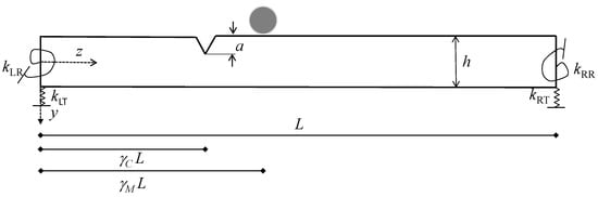
Figure 1.
Beam model under consideration.
In accordance with Hamilton’s principle, as detailed in [19], three systems of partial differential equations are derived for a Timoshenko beam in the truncated case considering the presence of a crack located at a distance denoted by L and a mass M situated at a distance L from the origin. The corresponding expressions are presented as follows:
with i = 1, 2, 3.
Define (z,t) as the transverse displacement and (z,t) as the total rotation, expressed as follows:
where represents the flexural rotation and denotes the slope of the deflection curve due to bending.
The solution for each ith system of Equation (1) is suggested to take the form of variable separation as outlined below:
in which i= and shows natural frequencies; thereby the system of differential Equation (1) transforms into:
The corresponding twelve boundary conditions associated with the presence of a crack, of a mass (as illustrated in Figure 1), and elastic end constraints for L < L are expressed as follows:
where is the flexibility rotational constant of the spring; for , Equations (8)–(11) interchange with Equations (12)–(15).
By introducing the subsequent dimensionless parameters
the system of differential Equations (4) and (5) assumes the following form:
where = L.
Differentiating from Equation (19) and substituting the appropriately derived expression into Equation (20), we arrive at the following result:
The solution of these differential equations is provided as follows:
where are constants to be determined, and the following coefficients are given:
with
Furthermore, one can derive () from Equation (20) by appropriately substituting the expression, for , which is obtained from Equation (19):
At the left end, the dimensionless boundary conditions for are expressed as follows:
The conditions for continuity of displacement and rotation at the crack location are written, respectively, in the following form:
and in corresponding to the mass M are given by
Ultimately, on the right end, we find
where the dimensionless nature of the stiffness of the constraints, the yield capacity of the crack, and the concentrated mass are
where is the non-dimensional crack sectional flexibility and depends on the extensions of the crack as defined in [15] (see Formula (11a)).
Compliance flexibility coefficients are typically represented as rotational springs or as a combination of translational and rotational springs, as demonstrated in the research conducted by Loya et al. [14]. Various methodologies have been reported in the literature to model cracks within beams. Among these, the approach utilizing a rotational spring, with its stiffness derived from principles of fracture mechanics, is particularly appealing for components resembling beams. In scenarios involving Timoshenko beams, an open edge crack is modeled using a single rotational spring.
Many researchers have neglected the concept of extensional compliance, considering its effects to be less significant than those associated with rotational compliance. In addition, this examination does not take into account the influence of translational compliance.
2.2. Crack Effect Theory for Beam Analysis
The crack effect along the beam is examined in this section, as shown in Figure 1. It is assumed that the crack is located at a height of a at a non-dimensional abscissa . The following connection can be used to define the mathematical description of a single-sided open crack:
where denotes the dimensionless height h given by =a/h, a denotes the height of the crack, and h represents the height of the cross section.
The function is obtained through the following equation:
being the flexibility function for a one-sided open edge crack exposed to a bending moment, as reported in [22]. It is worth mentioning that similar equations have been proposed for a double-sided open crack. By incorporating the suitably derived Equations (22)–(24) and (27) into boundary conditions (28)–(39), a set of twelve equations is formed, which encompasses the twelve unknown . In order for this system to exhibit non-trivial solutions, it is essential that the determinant of the coefficient matrix is zero. The infinite solutions that arise from the transcendental equation formed by solving this determinant will correspond to infinite free vibration frequencies.
3. Numerical Results and Discussion
This section aims to validate the suggested analytical approach by evaluating the effect of a mass, crack, and L/h ratios on the natural frequency of beams. Following the completion of numerical examples, the results were compared with those of earlier studies published in the literature. The numerical demonstrations used specialized software written in the Mathematica computer language [23]. The mechanical, geometrical, and physical properties discussed in [18] were applied to all numerical examples.
3.1. Beam with a Crack: Comparison of Results
This numerical analysis compares the first three natural frequencies associated with flexural vibrations, as estimated by the proposed Timoshenko truncated beam model, with the results shown in Table 3 of reference [18].
The three eigenvalues of a Timoshenko beam with different L/h ratios and boundary conditions are shown in Table 1 and were obtained using two different solution techniques: the truncated method and the exact solution [18]. The focus of this numerical example is the formulation developed for the free vibration of a Timoshenko beam, investigating four distinct boundary conditions in addition to the free condition (CF): simply supported (SS), simply supported with clamped ends (SSC), clamped–clamped (CC), and clamped–simply supported (CS). Simply supported, clamped, and free conditions are denoted by the acronyms S, C, and F, respectively. The L/h ratios examined include 3, 5, 7, and 9. For all cases, the dimensionless crack depth ratio is kept at = 0.35, while the dimensionless crack location parameter is consistently set at = 0.5. As can be seen in Table 1, the calculated values for the first three natural frequencies of the cracked beam using the suggested Timoshenko truncated beam model differ by no more than from those found in reference [18].

Table 1.
Comparison of the results with De Rosa and Lippiello (Timoshenko classical theory (TCT)) [18] and the proposed truncated model (TTT), in the presence of a crack, for various length–depth ratios and different boundary conditions: simply supported (S-S); simply supported–clamped (S-S-C); clamped–clamped (C-C); clamped–free (C-F).
3.2. Beam with a Crack: Variation of the Position Parameter
This research investigates a simply supported beam with a length-to-height ratio of L/h = 0.3, concentrating on different crack positions denoted by the dimensionless parameter . The first three natural frequencies are detailed in Table 2, which illustrates the variation of the parameter from 0.1 to 0.5, indicating that the crack is located at distances between and of the total length of the beam from the starting point. The findings presented in Table 2 indicate that, as the crack moves closer to the center of the beam, there is a notable reduction in the first natural frequency, which is associated with a reduction in structural stiffness.
Table 2.
First three natural frequencies = /2 for a Timoshenko beam with respect to the dimensionless crack position parameter .
3.3. Beam with a Crack: Clamped–Clamped Beam with Flexible Restraints at the Free End
This study investigates a beam that is fixed at the origin end but has flexible translation and rotation constraints at the free end on the right. The primary goal is to explore the variation in the first three dimensionless frequencies of the beam as the dimensionless rotational stiffness at the right extremity changes. In this example, the crack is located at the midpoint of the domain, specifically at = 0.5, while the dimensionless depth of the crack is given as = 0.35. For the sake of clarity, Figure 2 demonstrates how the first three dimensionless frequencies change in relation to the logarithm base 10 of the elastic support stiffness . The analysis reveals that the three dimensionless frequencies exhibit an increasing trend and ultimately converge to stable values once reaches 5. This phenomenon leads to the formation of an embedded beam featuring a bipendulum at its free end. In particular for we have that = 22.3457, = 291.9448, and = 1122.5413.

Figure 2.
First three dimensionless frequencies as rotational stiffness varies.
In the final example, the focus is on examining the variation of the initial three dimensionless frequencies in the context of a flexible constraint on translation at the free end. Consistent with the earlier discussion, the parameters are set to = 0.5 and = 0.35. It is evident that, when = 0, the problem is reduced to that of a cantilever beam.
Thus, Figure 3 shows the variation of the first three dimensionless frequencies with respect to the variation of translational rigidity, although again on a logarithmic scale, for convenience. As can be seen between = 4 and = 8, a change occurs in the curvature of the variation of the second and third dimensionless frequencies, to then stabilize and converge to the case of the simply supported beam–clamped beam as approaches ∞.
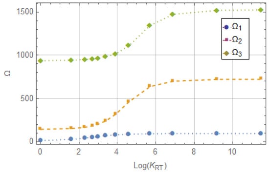
Figure 3.
First three dimensionless frequencies as translational rigidity varies.
3.4. Dynamic Problem of a Timoshenko Beam in the Presence of a Concentrated Mass and Variable Crack
Here, the dynamic response of a simply supported Timoshenko beam impacted by a concentrated mass and a developing crack is quantitatively explored. The analysis of this subject is especially complex, and structural engineering specialists have shown an increased interest in it in recent years. In addition to introducing nonlinear features and decreasing the beam’s stiffness, the presence of a crack can also cause the beam to vibrate nonlinearly. Localized stress concentrations and deformations result from the crack’s generation of a discontinuity in a beam’s stiffness.
Numerous researchers have explored the dynamic characteristics of Timoshenko beams that contain cracks and are subjected to concentrated masses [24,25,26]. Their findings have contributed significantly to the understanding of this complex phenomenon and have practical implications for the design and assessment of a range of structures, such as bridges, buildings, and aircraft. Importantly, these studies have revealed that the existence of a crack within a beam can markedly decrease its natural frequencies while simultaneously increasing its damping. Furthermore, the size of the concentrated mass has been found to influence the dynamic response of the beam.
3.4.1. Dynamic Problem of a Timoshenko Simply Supported Beam in the Presence of a Concentrated Mass and Variable Crack
To evaluate the reliability of the proposed truncated methodology, a simply supported beam with a length-to-height ratio of L/h = 0.3 and subjected to a fixed concentrated mass and a crack, which varies along the length of the beam, is analyzed.
Considering that the crack along the beam varies at values of = [0.1–0.9], and taking into account a non-dimensional mass intensity of 0.5, the first dimensionless frequency is determined for three different mass positions , specifically at 0.3, 0.5, and 0.7. Figure 4 shows the values of the first dimensionless frequency by varying the non-dimensional position of the crack along the beam. The data presented in Figure 4 show that the initial non-dimensional natural frequency of the beam exhibits sensitivity to both the magnitude of the additional mass and its positioning: for = 0.3 and that varies in the range [0.1–0.5] if increases decreases; for > 0.5 and = 0.5, increases. Also, for = 0.3 and that varies in the range [0.1–0.3] decreases, while it increases for , which varies in the range [0.4–0.7].
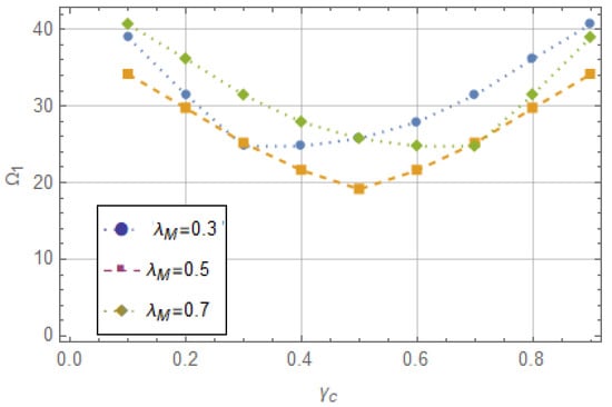
Figure 4.
First dimensionless frequency for three different values of mass and crack positions.
Figure 5 represents the first mode shapes of the beam with a mass at different normalized locations. It can be easily observed that the first natural frequency gradually decreases as the concentrated mass is moved from the two ends to the middle of the beam where the amplitude of the first mode shape is largest. Specifically, if = 0.5 and = 0.3 = 25.7701; for = 0.5 and = 0.5 = 19.1625 and, finally, for = 0.5 and = 0.7 = 25.7701. Consequently, it is expected that when the concentrated mass and the crack are in close proximity, there will be irregular variations in the natural frequency.
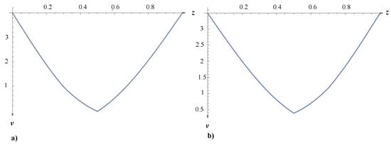
Figure 5.
Effect of crack and mass at different locations on Mode-I: (a) = 0.3 and (b) = 0.7.
3.4.2. Dynamic Problem of a Timoshenko Clamped–Free Beam in the Presence of a Concentrated Mass and Crack
The last numerical example discussed concerns a clamped–free beam structure with a crack in the midpoint of the beam, parameterized by = 0.5, and the presence of a concentrated mass.
The first three values of the dimensionless frequencies are reported in Table 3, assuming a mass with a non-dimensional value ranging from [0,1] at the left end.
Table 3.
First three natural frequencies for a Timoshenko beam with respect to the dimensionless crack position parameter = 0.5 and a mass with non-dimensional value varying from [0,1].
Table 3 shows that when the crack is positioned 0.5 from the beam’s origin, the non-dimensional free frequencies value decreases as the mass’s non-dimensional value increases.
4. Concluding Remarks
This paper investigates the dynamic behavior of the Timoshenko cracked beam when subjected to a mass. In turn, it is assumed that the beam’s ends are restrained by transverse and rotational elastic springs. The cracked beam’s governing equations of motion were calculated using truncated Timoshenko theory (TTT). The study examined how the translational and rotational stiffness coefficients, crack locations, and mass affect the natural frequencies of a beam. The results show that the presence of a crack affects the natural frequencies value, and the location of the crack has a significant impact on these values. Finally, to demonstrate the efficacy of the suggested method, typical results are presented and compared with some results available in the literature. The reported results are in good agreement with existing research. In particular, the following deductions are made:
- The change in natural frequencies depends largely on the boundary conditions and the length/depth ratios of the beam.Boundary conditions (such as simply supported, clamped, free, or a combination of these) influence the constraints on the deflection and rotation of the beam, which in turn affect the stiffness and modal properties. The eigenvalue problem, which governs the beam’s natural frequencies, changes with each set of boundary conditions. The aspect ratio of the beam has a direct impact on stiffness and slenderness ratio , which in turn influences the natural frequency value. In general, if the length-to-depth ratio increases, the stiffness relative to mass decreases, resulting in lower natural frequencies. In contrast, a smaller ratio enhances structural stiffness while increasing natural frequencies. Simply supported beams have lower fundamental frequencies than clamped beams due to the smaller value of (the first mode constant). Similarly, increasing reduces frequency when decreases relative to .
- The crack plays a key role in the dynamic behavior of the beam: the values of the natural frequencies increase when the dimensionless transverse and rotational stiffness parameters in the flexible supports increase.The crack introduces a localized reduction in stiffness, causing an uneven distribution of bending rigidity along the beam. As a result, the effective stiffness in the natural frequency equation is altered. The depth, location, and orientation of the crack affect the resistance to deformation of the beam, which results in variations in the modal shapes and frequencies.
- The first non-dimensional natural frequency of the beam is sensitive to added mass and its location.Adding mass alters the system’s overall inertial properties, specifically the effective mass involved in vibration for various modes. The placement of the added mass affects the mass distribution and coupling with mode shapes, influencing how the beam vibrates. The natural frequency is determined by the equilibrium of stiffness and inertia. Adding bulk increases inertia without changing stiffness directly, lowering the natural frequency. The first mode of frequency is particularly sensitive because it often involves the greatest relative displacement along the beam, making it more susceptible to changes in the mass distribution.
This method works quite well for studying Timoshenko beam vibration issues. The novel part of the suggested strategy is that it makes use of a variational approach in truncated theory, which makes it easier to derive the equation of motion using classical theory. Furthermore, a clear analogy between the two theoretical structures is clarified by this framework. Finally, it has been demonstrated that the differential equations and their associated boundary conditions using variational formulations to solve the dynamic problem of Timoshenko truncated beams have the same form as those derived using the direct method.
Author Contributions
Conceptualization, M.A.D.R. and M.L.; methodology, M.A.D.R., M.L., M.T.P. and C.C.; software, M.A.D.R., H.D.M. and A.O.; validation, M.A.D.R., M.L., M.T.P. and C.C.; formal analysis, M.A.D.R., M.L. and A.O.; investigation, M.L. and H.D.M.; resources, M.A.D.R. and M.L.; data curation, M.A.D.R. and M.L.; writing—original draft preparation, M.L.; writing—review and editing, M.A.D.R., M.L. and M.T.P.; visualization, M.A.D.R. and M.L.; supervision, M.A.D.R., M.L. and M.T.P. All authors have read and agreed to the published version of the manuscript.
Funding
This research received no external funding.
Institutional Review Board Statement
Not applicable.
Informed Consent Statement
Not applicable.
Data Availability Statement
The original contributions presented in this study are included in the article. Further inquiries can be directed to the corresponding author.
Conflicts of Interest
The authors declare no conflicts of interest.
References
- Yang, Y.; Zhang, Y.; Tan, X. Review on Vibration-Based Structural Health Monitoring Techniques and Technical Codes. Symmetry 2021, 13, 1998. [Google Scholar] [CrossRef]
- Meirovitch, L. Fundamentals of Vibrations; McGraw-Hill: Boston, MA, USA, 2001; ISBN 978-0-07-041345-0. [Google Scholar]
- Doebling, S.W.; Farrar, C.R.; Prime, M.B.; Shevitz, D.W. Damage Identification and Health Monitoring of Structural and Mechanical Systems from Changes in Their Vibration Characteristics: A Literature Review; SAGE Publications: New York, NY, USA, 1996. [Google Scholar]
- Chondros, T.G.; Dimarogonas, A.D.; Yao, J. A continuous cracked beam vibration theory. J. Sound Vibr. 1998, 215, 17–34. [Google Scholar] [CrossRef]
- Adams, R.D.; Cawley, P.; Pye, C.J.; Stone, B.J. A vibration technique for non-destructively assessing the integrity of structures. J. Mech. Eng. Sci. 1978, 20, 93–100. [Google Scholar] [CrossRef]
- Sinha, J.K.; Friswell, M.I.; Edwards, S. Simplified models for the location of cracks in beam structures using measured vibration data. J. Sound Vibr. 2002, 251, 13–38. [Google Scholar] [CrossRef]
- Thatoi, D.; Jena, P.; Acharya, A.; Mohapatra, S.; Nanda, J. Analysis of the dynamic response of a cracked cantilever beam. In Proceedings of the AICTE Sponsored National Conference on Emerging Trend and its Application in Engineering (NCETAE), Shillong, India, 4–5 March 2011. [Google Scholar]
- Narkis, Y. Identification of crack location in vibrating simply supported beams. J. Sound Vibr. 1994, 172, 549–558. [Google Scholar] [CrossRef]
- Khiem, N.; Lien, T. A simplified method for natural frequency analysis of a multiple cracked beam. J. Sound Vibr. 2001, 245, 737–751. [Google Scholar] [CrossRef]
- Caddemi, S.; Calio, I. Exact closed-form solution for the vibration modes of the Euler- Bernoulli beam with multiple open cracks. J. Sound Vibr. 2009, 327, 473–489. [Google Scholar] [CrossRef]
- Khiem, N.; Hai, T. A closed-form solution for free vibration of beams with arbitrary number of cracks. In Proceedings of the Scientific Conference Dedicated to 35th Anniversary of Vietnam Academy of Science and Technology, Hanoi, Vietnam, 26 October 2010; Volume 1, pp. 30–42. [Google Scholar]
- Timoshenko, S. On the correction for shear of the differential equation for transverse vibrations of prismatic bars. Philos. Mag. 1921, 41, 744–746. [Google Scholar] [CrossRef]
- Li, Q. Vibratory characteristics of Timoshenko beams with arbitrary number of cracks. J. Eng. Mech. 2003, 129, 1355–1359. [Google Scholar] [CrossRef]
- Loya, J.; Rubio, L.; Fernández-Sáez, J. Natural frequencies for bending vibrations of Timoshenko cracked beams. J. Sound Vibr. 2006, 290, 640–653. [Google Scholar] [CrossRef]
- Khaji, N.; Shafiei, M.; Jalalpour, M. Closed-form solutions for crack detection problem of Timoshenko beams with various boundary conditions. Int. J. Mech. Sci. 2009, 51, 667–681. [Google Scholar] [CrossRef]
- Elishakoff, I.; Hache, F.; Challamel, N. Critical contrasting of three versions of vibrating Bresse- Timoshenko beam with a crack. Int. J. Sol. Struct. 2017, 109, 143–151. [Google Scholar] [CrossRef]
- Khiem, N.; Hung, D. A closed-form solution for free vibration of multiple cracked Timoshenko beam and application. Vietnam J. Mech. 2017, 39, 315–328. [Google Scholar] [CrossRef] [PubMed]
- De Rosa, M.; Lippiello, M. Closed-form solutions for vibrations analysis of cracked Timoshenko beams on elastic medium: An analytical approach. Eng. Struc. 2021, 236, 111946. [Google Scholar] [CrossRef]
- De Rosa, M.; Lippiello, M.; Elishakoff, I. Variational Derivation of Truncated Timoshenko- Ehrenfest Beam Theory. J. Appl. Comput. Mech. 2022, 8, 996–1004. [Google Scholar]
- De Rosa, M.; Lippiello, M.; Elishakoff, I. Reduced Theories for Thick Shells. In Proceedings of the ASME 2022 International Mechanical Engineering Congress and Exposition, Columbus, OH, USA, 30 October–3 November 2022. IMECE2022-96660, V005T07A003. [Google Scholar]
- De Rosa, M.A.; Elishakoff, I.; Onorato, A.; Lippiello, M. Dynamic Analysis of a Timoshenko–Ehrenfest Single-Walled Carbon Nanotube in the Presence of Surface Effects: The Truncated Theory. Appl. Mech. 2023, 4, 1100–1113. [Google Scholar] [CrossRef]
- Ostachowitz, W.M.; Krawczuk, M. Analysis of the effect of cracks on the natural frequencies of a cantilever beam. J. Sound Vibr. 1991, 150, 91–201. [Google Scholar] [CrossRef]
- Wolfram, S. The Mathematica 8; Cambridge University Press: Cambridge, UK, 2010. [Google Scholar]
- Khoa, N.V.; Quang, N.V. Free vibration of a cracked double-beam carrying a concentrated mass. Vietnam J. Mech. VAST 2016, 38, 279–293. [Google Scholar] [CrossRef] [PubMed][Green Version]
- Shafiei, M.; Khaji, N. Analytical solutions for free and forced vibrations of a multiple cracked Timoshenko beam subject to a concentrated moving load. Act. Mech. 2011, 221, 79–97. [Google Scholar] [CrossRef]
- Murat, R.; Quang, N.V. Vibration of a cracked cantilever beam under moving mass load. J. Civil Eng. Manag. 2012, 18, 106–113. [Google Scholar]
Disclaimer/Publisher’s Note: The statements, opinions and data contained in all publications are solely those of the individual author(s) and contributor(s) and not of MDPI and/or the editor(s). MDPI and/or the editor(s) disclaim responsibility for any injury to people or property resulting from any ideas, methods, instructions or products referred to in the content. |
© 2025 by the authors. Licensee MDPI, Basel, Switzerland. This article is an open access article distributed under the terms and conditions of the Creative Commons Attribution (CC BY) license (https://creativecommons.org/licenses/by/4.0/).