Article

Numerical Model for Studying the Properties of a New Friction Damper Developed Based on the Shell with a Helical Cut

by
Andrii Velychkovych
1,*,
Vasyl Mykhailiuk
2 and
Andriy Andrusyak
1
1
Department of Construction and Civil Engineering, Ivano-Frankivsk National Technical University of Oil and Gas, 15 Karpatska Str., 76019 Ivano-Frankivsk, Ukraine
2
Department of Oil and Gas Field Machinery and Equipment, Ivano-Frankivsk National Technical University of Oil and Gas, 15 Karpatska Str., 76019 Ivano-Frankivsk, Ukraine
*
Author to whom correspondence should be addressed.
Appl. Mech. 2025, 6(1), 1; https://doi.org/10.3390/applmech6010001
Submission received: 26 November 2024 / Revised: 27 December 2024 / Accepted: 31 December 2024 / Published: 2 January 2025

Abstract

:
Friction dampers based on the effects of dry friction are attractive to engineers because of their simple design, low manufacturing and maintenance costs, and high efficiency under heavy loads. This study proposes a new damper design based on an open shell with a deformable filler, with the shell cut along a cylindrical helical line. The key idea in developing the design was to use the bending effect of the shell in contact with the weakly compressible filler. Another idea was to use the frictional interaction between the filler and the open shell to obtain the required damping characteristics. The working hypothesis of this study was that, ceteris paribus, a change in the configuration of the shell cut would cause a change in the stiffness of the structure. To analyse the performance characteristics of the proposed damper and test the hypothesis put forward, a numerical model of the shell damper was built, and a boundary value problem was formulated and solved for the frictional interaction between the shell cut along the helical line and the weakly compressible filler, taking into account the dry friction forces between them. As a result, the strength, stiffness, and damping properties of the developed damper were investigated, and a comparative analysis of the new design with the prototype was carried out. It is predicted that the proposed friction damper will be used in the energy and construction industries, in particular in drilling shock absorbers for the oil and geothermal industries, as well as in earthquake-resistant structures.

1. Introduction

Today, the use of dampers, elastic elements, and shock absorbers is relevant in various industries, including construction [1,2], automotive [3], energy [4], aerospace engineering [5,6], etc. The popularity of these devices is due to their importance for implementing strategies to ensure the safety, comfort, and efficiency of production and household processes. Many studies have addressed the role of dampers in these industries, focusing primarily on improving their performance in specific applications, such as seismic safety, vehicle suspensions, and machinery vibration isolation. However, there is still a gap in understanding how different damper designs could be optimised for extreme operational environments, such as deep drilling and high-load systems.
First of all, the use of dampers reduces the risks associated with vibrations and shocks, preventing accidents and ensuring the reliability of structures. In addition, dampers improve comfort on production sites, in vehicles, and in buildings by reducing vibrations and noise [7,8,9]. In industrial machinery and equipment, they increase efficiency by reducing component wear and extending equipment life [10,11]. This reduces maintenance and repair costs, which is beneficial for businesses. Dampers also help to adapt structures to changing operating conditions, such as changes in loads, temperature, and other factors, which ensures the flexibility and reliability of systems in different environments [12,13,14]. Despite the widespread application of dampers, challenges persist in designing systems that maintain stable performance under varying loads and extreme environmental conditions.
Today, commonly used dampers are classified according to their design features and operating principles. Viscous dampers are devices that utilise the resistance to fluid or gas movement [15]. In viscous dampers, the piston moves inside a cylinder filled with liquid or gas, and hydrodynamic resistance occurs, which converts kinetic energy into thermal energy [16,17]. It should be noted that this is the most common group of dampers, which includes hydraulic, pneumatic, and hydropneumatic devices. However, this approach is less effective when applied to high-load systems where the fluid or gas may not provide the necessary resistance, leaving a gap for alternatives such as friction-based dampers.
Elastomeric and rubber–metal dampers (gaskets for motors and mechanisms, rubber–metal anti-vibration supports, etc.) absorb mechanical energy due to internal friction in the material, and their effectiveness depends significantly on the viscoelastic properties of the material from which the damper is made [18,19,20,21]. The next group is electromagnetic dampers, which create resistance due to the interaction of magnetic fields; in particular, when a conductor moves in a magnetic field, an electromotive force arises that generates a current and creates a damping effect [22,23]. Piezoelectric dampers use piezoelectric materials that generate an electric charge under mechanical stress, which is used to dampen vibrations through electronic components [24,25]. Magnetorheological dampers use liquids that change their viscosity under the influence of a magnetic field, which actually allows for controlling the damping characteristics by changing the strength of the magnetic field [26,27,28,29]. In contrast to fluid-based dampers, dry friction dampers offer simplicity, cost-effectiveness, and reliability under extreme load conditions, particularly in applications involving significant mass or slow motion. Dry friction dampers use the frictional force between solids to dissipate the energy of vibrations or shocks [30]. Dry friction dampers are used in industrial machinery, aviation, automotive brakes, earthquake-resistant structures, etc. [31,32,33]. Dry friction dampers attract engineers with their simple design, low production and maintenance costs, and efficiency under high loads.
Dry friction dampers have unique characteristics and play a key role in systems where the nonlinearity of vibration protection devices is important [34,35]. They are highly effective at damping low-frequency vibrations, especially at low speeds. This makes them indispensable in systems with a large mass or slow motion, such as in earthquake-resistant structures, where nonlinear behaviour is important for active energy absorption during strong vibrations [36,37]. Nevertheless, the modelling of dry friction dampers remains complex, as their behaviour involves nonlinearities such as hysteresis and stick–slip phenomena that are difficult to predict and model. In stabilisation systems, such as car suspensions, they provide precise control and stable damping under variable loads. This effect is achieved through a stable friction force that is independent of the speed of movement. The nonlinear characteristics make dry friction dampers indispensable in applications where damping stability under different load conditions is important.
Dry friction dampers are classified according to various criteria that determine their applications and effectiveness in different systems. The classification by friction type includes models with Coulomb friction [38], discontinuous friction, stick–slip friction [39,40], and variable friction [41], while the classification by design features covers cylindrical, conical, disc, plate, and various variants of combined mechanisms [42,43]. These types allow for dampers to be adapted to specific requirements and operating conditions. In particular, in the automotive industry, they are used in braking systems, suspensions, and body stabilisers, providing reliability at a low cost, although they require regular maintenance to prevent wear and tear [44,45,46]. In the mining and oil and gas industries, friction dampers are used to regulate the dynamic operation of rock-destroying tools, drill and casing strings, and elements of deep-well pumping equipment [47,48,49]. In aerospace engineering, they protect mechanical components from extreme loads; in construction, they are used in earthquake-resistant structures to absorb earthquake energy; in industry, they reduce vibrations in heavy machinery, elevators, and cranes [50,51,52,53]. In household washing machines, dry friction dampers ensure the stability of the drum during washing [54]. Although friction dampers have been successfully applied across various industries, new challenges emerge when applying them in specific scenarios, such as the high-pressure or high-temperature conditions encountered in deep-well drilling operations.
Modelling dry friction dampers is a challenging task due to their nonlinear behaviour. In well-known studies, we can find the use of analytical methods [55,56,57], the creation of numerical models [58,59], and experimental and hybrid techniques [60,61,62]. However, while existing studies provide useful insights into the behaviour of friction dampers, there remains a need for advanced models that can accurately predict their performance under complex loading conditions, such as those encountered in deep oil and gas drilling. The nonlinearity of the friction force, hysteresis phenomena, and dynamic switching between sliding and stopping create additional difficulties that require researchers to apply special approaches when developing mechanical and mathematical models.
This study was motivated by a real industrial problem. Previously, shell elastic elements based on a solid cylindrical shell with a deformable filler were successfully used to design shock absorber elements used in deep oil and gas and geothermal well drilling [63]. When drilling with roller cone bits, such elastic elements are able to work effectively under high loads (150–200 kN axial force load plus operational kinematic load) and with a limited transverse dimension (borehole diameter of about 140–180 mm). However, today, the most effective method of rock destruction for the construction of deep wells is drilling with polycrystalline diamond compact (PDC) bits [64,65,66]. Accordingly, the requirements for the characteristics of elastic elements of drill shock absorbers have changed. The axial loads on PDC bits are significantly lower, and the possible movements of the drilling tool elements are greater. It was necessary to significantly reduce the stiffness of the shell elastic elements and, as a result, to reduce the resonant frequencies of the dynamic system. In the process of solving this problem, we came up with the idea of using an open cylindrical shell with a cut along the generatrix as the main bearing link of the friction damper for the drill shock absorber. In fact, this step allowed for us to obtain a structurally anisotropic friction damper bearing link (this link remained rigid in the axial direction but became compliant in the tangential direction).
Figure 1 shows experimental samples and a conceptual diagram of a friction damper with an open shell. The peculiarity of the presented design is the presence of a section of the bearing link-shell along its generatrix. The operating load applied to the pushers (1) causes them to move inside the cut shell (2), compressing the deformable filler (3). At the same time, the weakly compressible filler (3) changes its shape and enters into frictional interaction with the open shell (2). As a result, the shell deforms and accumulates potential elastic deformation energy. The main part of the damper’s compatibility is provided by the change in the shape of the weakly compressible filler due to the bending deformation of the shell. When the external load decreases (or disappears), the moving parts of the damper try to return to their original position using the stored energy. Mutual slippage with friction of the deformable filler (3) and the open shell (2) leads to the dissipation of some of the energy of external influences that was supplied to the damper. To expand the scope of application of such devices, it would be good to develop a simple way to change their performance characteristics.
The shell damper is essentially a deformable system with positional dry friction. The physical and mathematical modelling of the loading process of such devices with non-monotonic load generates nonlinear problems regarding the contact interaction of a thin-walled shell with a weakly compressible filler. Such problems are quite difficult to solve analytically; therefore, in our study, we preferred to build a numerical model of the shell damper. In the context of the problem under consideration, we are particularly interested in the problems of contact interaction of rod systems with the environment [67,68,69], contact interaction of cut edges in bending of thin shells [70,71,72,73,74], and limit equilibrium of thin-walled structures on an elastic base [75,76]. It is worth noting a publication with a review of dynamic systems with different representations of dry friction effects [77].
The theoretical foundations for the calculation of dampers with a cylindrical shell with a cut along the generatrix have already been developed, and the influence of the open shell profile on the material consumption of the damper has been studied [21,78]. However, the problem of the influence of the configuration of the open shell cut on the strength and deformation properties of the damper has not yet been studied.
The aim of this study is to investigate the behaviour of a damper constructed on the basis of an open cylindrical shell with a deformable filler when the shell cut is made along a cylindrical helical line. It is planned to investigate the strength, stiffness, and damping capacity of such a device to assess the possibility of adjusting the stiffness of the damper by changing the configuration of the shell cut.

2. Materials and Methods

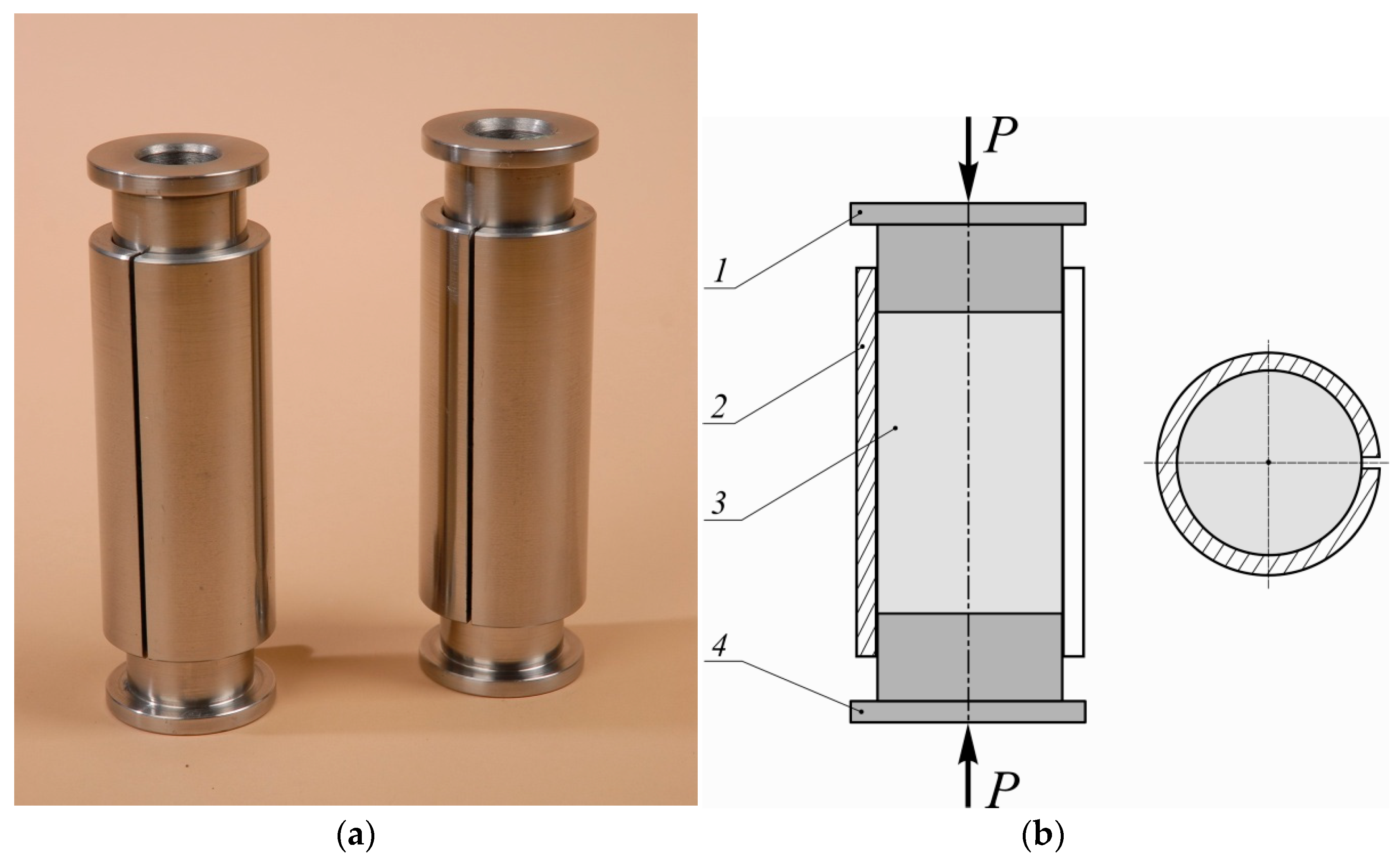
2.1. Hypothesis on the Method of Adjusting the Stiffness of the Shell Damper

Today, dampers are expected to not only perform the basic function of energy absorption but also to be able to be quickly adjusted to changing operating conditions without significantly increasing the cost or complexity of the design. An affordable and cost-effective way to adjust the stiffness of the damper is an important factor that often determines the operational suitability of such a device. The experience of manufacturing and operating shell shock absorbers as well as conducting test experiments allowed for the authors to put forward a hypothesis about the method of adjusting the stiffness of the shell damper. This method is as follows. In a friction damper with an open shell, the shell is cut at an angle to the generatrix so that the shell sweep takes the form of a parallelogram, the internal acute angle of which can vary in the range 90 α 45 (Figure 2). At the same time, when α = 45 , the maximum change in damper characteristics (in particular, an increase in stiffness) compared to the basic design is ensured. In this case, the shell is cut along a cylindrical helical line. This line is located on the surface of the shell and is formed by the uniform movement of a point along a generatrix that rotates uniformly around the shell axis. The length of the shell is the step of such a helical line.
The closer the angle α is to the value of 90 , the less noticeable are the changes in the performance characteristics of the damper. If α = 90 (i.e., the cut is made along the generatrix), we obtain the basic version of the shell damper (Figure 1).
To determine the operational characteristics of the proposed damper (Figure 2) as well as to assess the possibility of adjusting the stiffness of the damper by changing the configuration of the shell cut, it is necessary to consider the problem of interaction of the shell cut along the helical line with an elastic filler. For this purpose, it was decided to build a finite element model of the device.

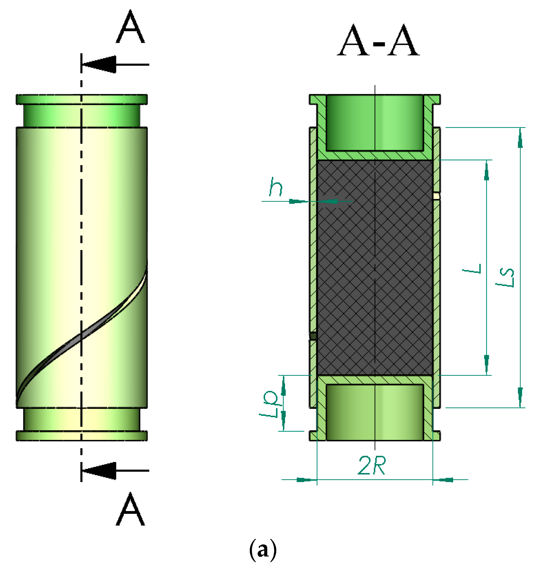
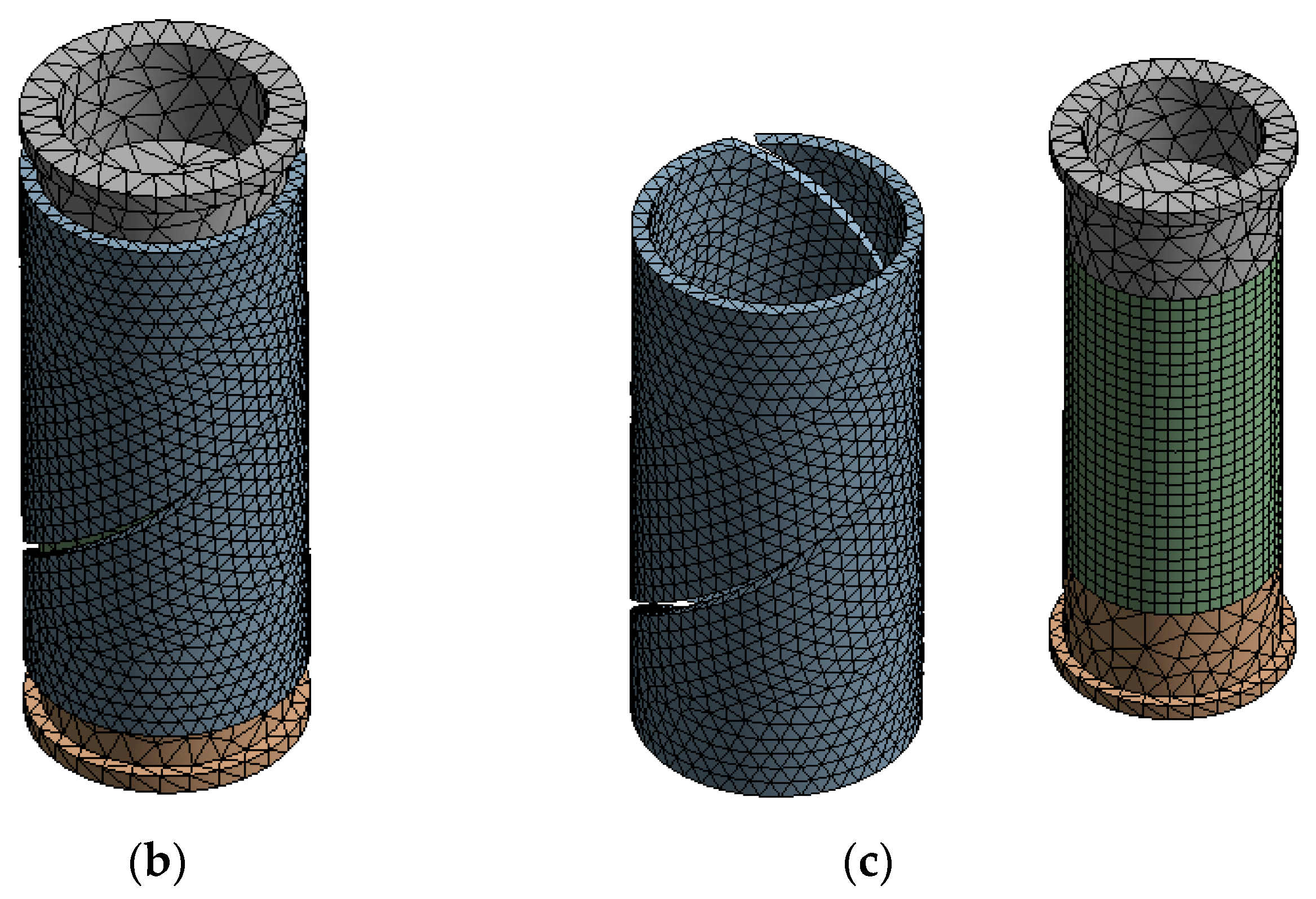
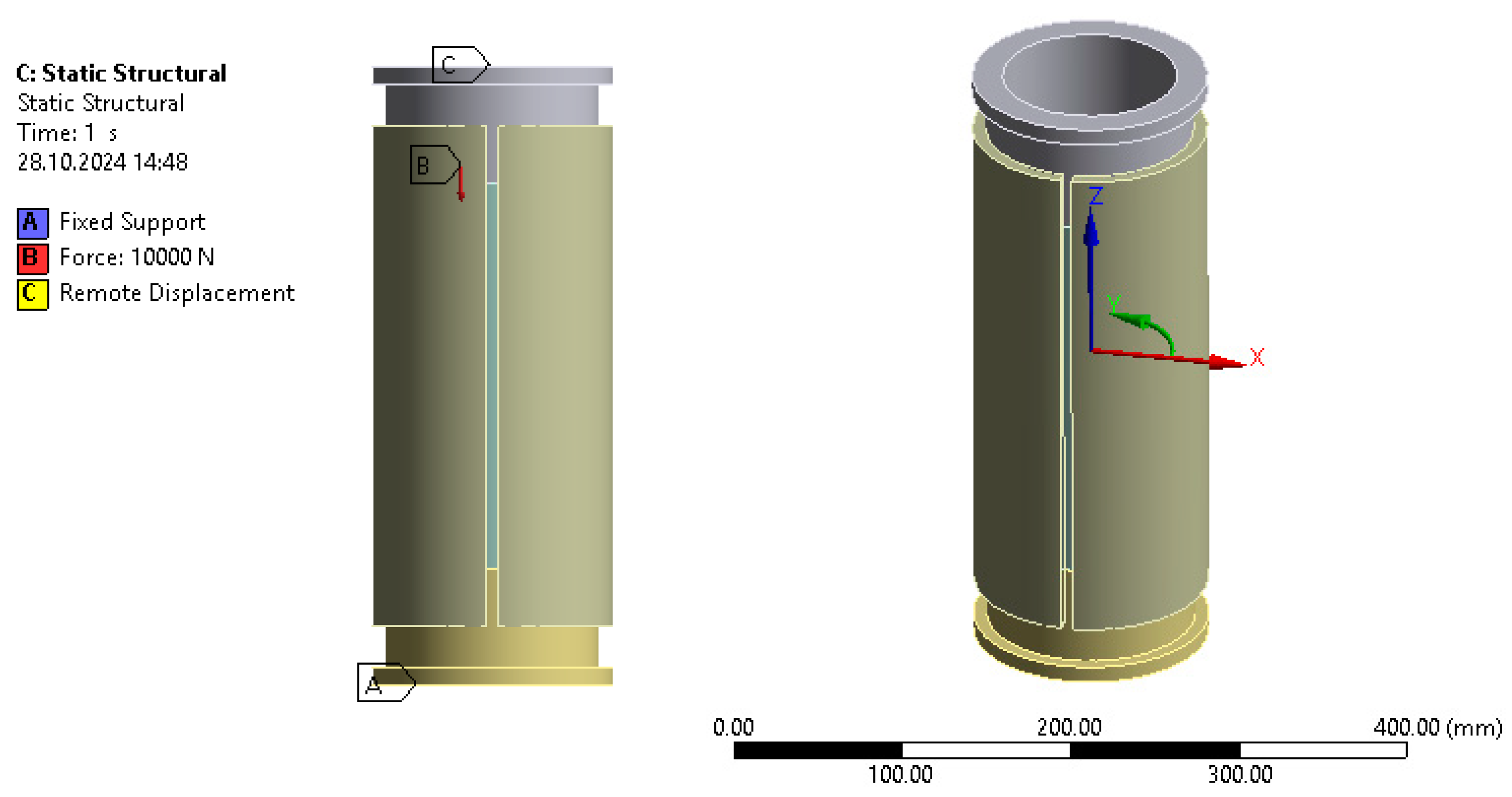
2.2. Numerical Model of a Friction Damper Constructed on the Basis of an Open Shell with a Deformable Filler

Let us formulate a boundary value problem of the theory of elasticity on the frictional interaction of an open shell and an elastic filler, taking into account the dry friction forces between them. An elastic deformable cylinder (hereafter referred to as a filler) with radius R and length L is placed in an open elastic shell of thickness h and length L s (Figure 3a). The shell is cut along a cylindrical helical line. A weakly compressible, deformable aggregate is compressed at the ends by pushers to which an external load P is applied. The interaction between the contacting surfaces of the filler and the open shell as well as between the working surface of the pusher and the end sections of the filler is described by the law of dry friction, which gives the system a significant nonlinearity. In order to determine the stress–strain state of this multicomponent system, it is necessary to construct a numerical solution that takes into account the specific features of contact interaction, in particular, the heterogeneous distribution of contact pressure between the contacting surfaces. To do this, it is necessary to create finite element models of the filler, pusher, and open shell. They must meet the required level of rigour to adequately describe the mixed contact problem and ensure accurate reproduction of the key parameters of the stress–strain state, in particular, the dependence of stresses and displacements on the geometric and mechanical parameters of the system.
The finite element model of the damper was developed in Ansys Workbench 2022R1. Each component was modelled as a separate array of finite elements, which made it possible to take into account the individual characteristics of the materials and geometry of the elements.
The Hex Dominant method was used to create the filler model. This method is typically used to generate a computational mesh when an object has a regular shape or contains fairly large homogeneous areas. The Hex Dominant method is based on the creation of hexahedral elements, which are known for their high accuracy in the analysis of deformations and stresses. Hexahedral elements have a more regular arrangement of nodes, which allows for high computational stability, especially in problems with large deformations. For a filler made of weakly compressible elastomers, the Hex Dominant method is the best choice, as it allows for a more accurate representation of the stress–strain state of a material subject to significant elastic deformation. In our model, we chose an average element edge length of 0.8 cm, which provides sufficient detail without increasing the number of nodes too much.
The Tetrahedrons method was used to model an open cylindrical shell with a helical cut. This method allows for efficient approximation of the surface contour and adaptation to shape changes. Tetrahedral elements are versatile and well suited for applications where complex geometry requires increased mesh flexibility. The Patch Independent mesh generation technology automatically overlays the mesh on the design area and cuts off fragments that go beyond the geometry. This avoids distortions and improves mesh adaptability to irregular shell shapes. The average edge length of the tetrahedral elements is 10 mm, which is considered optimal for maintaining the accuracy of modelling contact problems.
ANSYS used automatic mesh generation by default when modelling the pushers. The software system independently selected the meshing parameters using a coarser mesh (compared to other damper components), which is optimal for objects with rigid characteristics. This is due to the fact that the pushers in this model behave as absolutely rigid bodies that do not undergo significant deformations during loading. Since the stress–strain state of the pushers was not the object of study, a detailed mesh for them was not necessary. This approach allows for the reduction of the number of elements and optimises computing resources without losing accuracy in the models.
To test the effect of mesh density on the results, a mesh independence study was conducted [79]. This study made it possible to select a mesh density at which the analysis results remain stable without changing significantly with further reduction in the finite element size. Several iterations were performed to reduce the size of the elements and compare the results in order to determine the optimal balance between accuracy and resource intensity of the model. It was found that further reduction in the finite elements does not lead to a noticeable improvement in accuracy, so the selected mesh density is effective for our study.
One of the key aspects of the model is the description of the contact interaction between the shell and the filler. For this purpose, ANSYS used the ‘Frictional’ contact type, with a friction coefficient initially set to 0.2, which was changed during the experimental studies. This type of contact allows for the models to interact in a dry friction manner, where displacement is possible only when a certain level of friction force is overcome. To model the constraints with minimal penetration of the contact surfaces, the Augmented Lagrange method was chosen. This method ensures minimal penetration due to the adaptive variation in penalty coefficients in contact conditions. Unlike other methods, such as Pure Penalty, the Augmented Lagrange method provides more stable and accurate results because it adaptively adjusts contact constraints, reducing the risk of distortion [80,81,82]. In addition, this method requires a moderate computational time, which is an additional advantage in modelling complex contact problems. Thus, the contact parameters were set as follows: friction coefficient—0.2 (with the possibility of its adjustment); contact formulation—‘Augmented Lagrange’; penetration tolerance—0.0015, which ensures accurate compliance with the penetration limits, avoiding excessive displacement of surfaces; normal stiffness factor—‘Program controlled’, which allows for the system to automatically select the optimal value to ensure the stability of calculations. This setting of contact conditions ensures the reliability of the model, especially given the need to take into account friction in the system.
From a mechanical point of view, the surface contact between the damper components was modelled as a one-way contact with Coulomb friction, which allows for a realistic representation of the interaction between the filler and the shell. The one-way contact is described by a system of inequalities that models the ability of the surfaces to contact or break contact depending on the magnitude and direction of the applied loads. This system of inequalities describes the condition under which contact can only exist under compressive conditions on the contact surfaces and ensures that contact stresses disappear as the surfaces are removed. In this case, the tangential forces are determined by the Coulomb friction condition, and when they exceed the limit value, slippage occurs, and the surfaces can be relatively displaced, modelling slippage zones. This formulation allows for the prediction of changes in the ratio of adhesion and slipping zones (and possibly the appearance of separation zones—contact breakage) that occur during non-monotonic loading of the damper, providing a flexible response to dynamic changes in the system. It should be noted that this approach to modelling is critical for systems where the surfaces may be repeatedly approached and removed, as in the case of friction dampers.

3. Results and Analysis

This study analysed a friction damper with geometric parameters typical of shell drill shock absorbers: L / R = 5 , h / R = 1 / 10 (Figure 3a). Structural chromium–silicon steel 60SiCr7 (yield strength— σ 0.2 = 1450       MPa , Young’s module— 2.1 10 11   Pa , shear module— 8 10 10   Pa , Poisson’s ratio—0.31) was used as the material of the open shell. The material of the deformable damper filler was raw rubber with increased oil and petrol resistance (modulus of elasticity— 2 10 7   Pa , shear module— 7 10 6   Pa , Poisson’s ratio—0.4995). The geometric parameters of the damper were as follows: inner radius of the open shell R = 80   mm ; shell length L s = 0.5   m ; length of deformable filler L = 0.4   m ; shell wall thickness h = 8   mm ; length of the working part of the pusher L p = 110   mm ; friction coefficient of shell-filler and pusher-filler contact pairs— f = 0.2 ; and the range of change in the external load on the pusher P = 0 100   kN .
In the first stage of this study, the external load P was assumed to be constant or at least monotonically increasing. It was applied to the upper pusher, while the lower pusher was fixed. The stress–strain state of the structure was studied in cylindrical coordinates, and given the symmetry of the structure relative to a plane equidistant from the pushers, the origin of the cylindrical XYZ coordinate system was placed in the centre of the structure (Figure 4a). Here, X is the radial coordinate, Y is the angular coordinate, and Z is the axial coordinate.

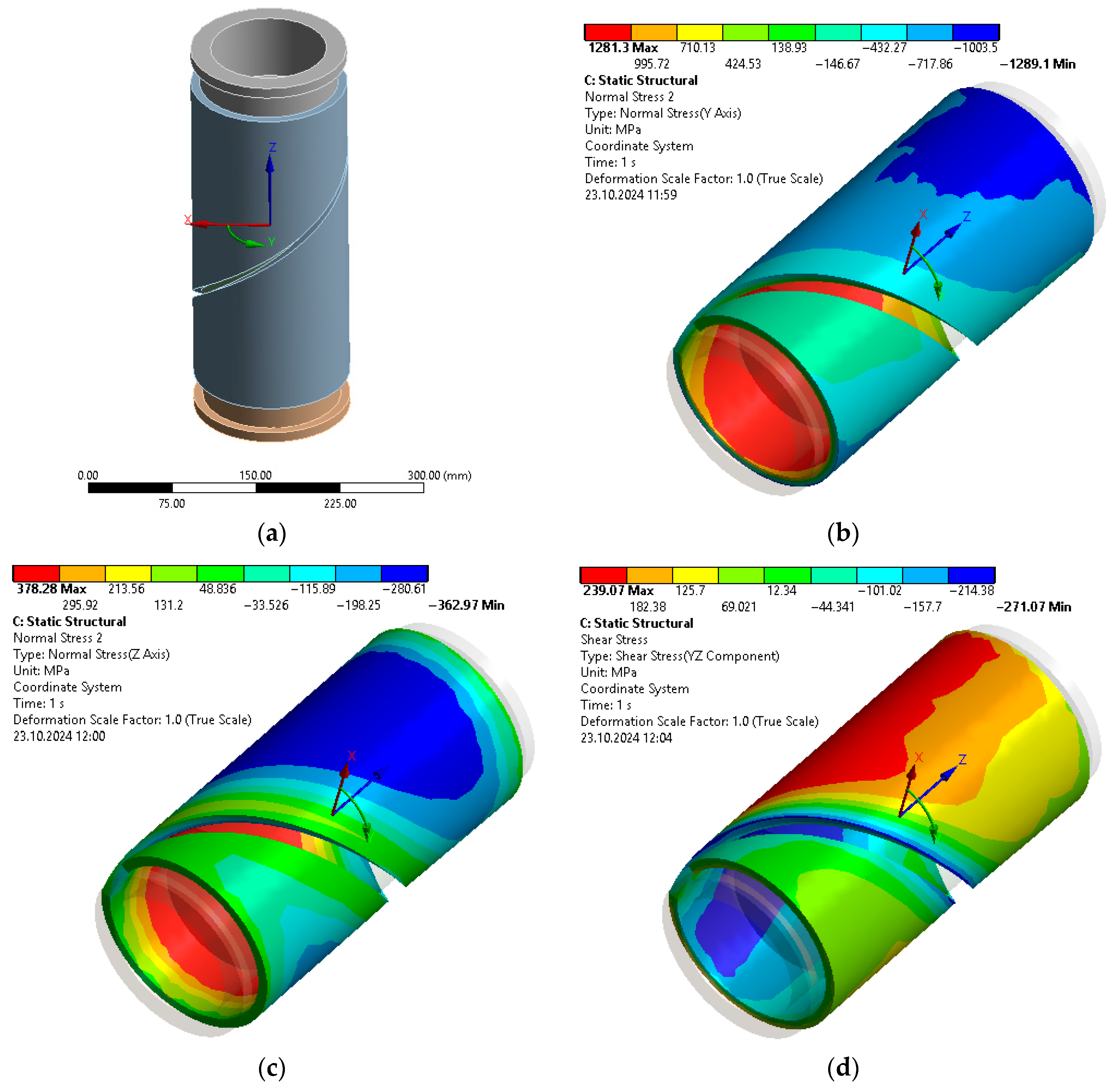
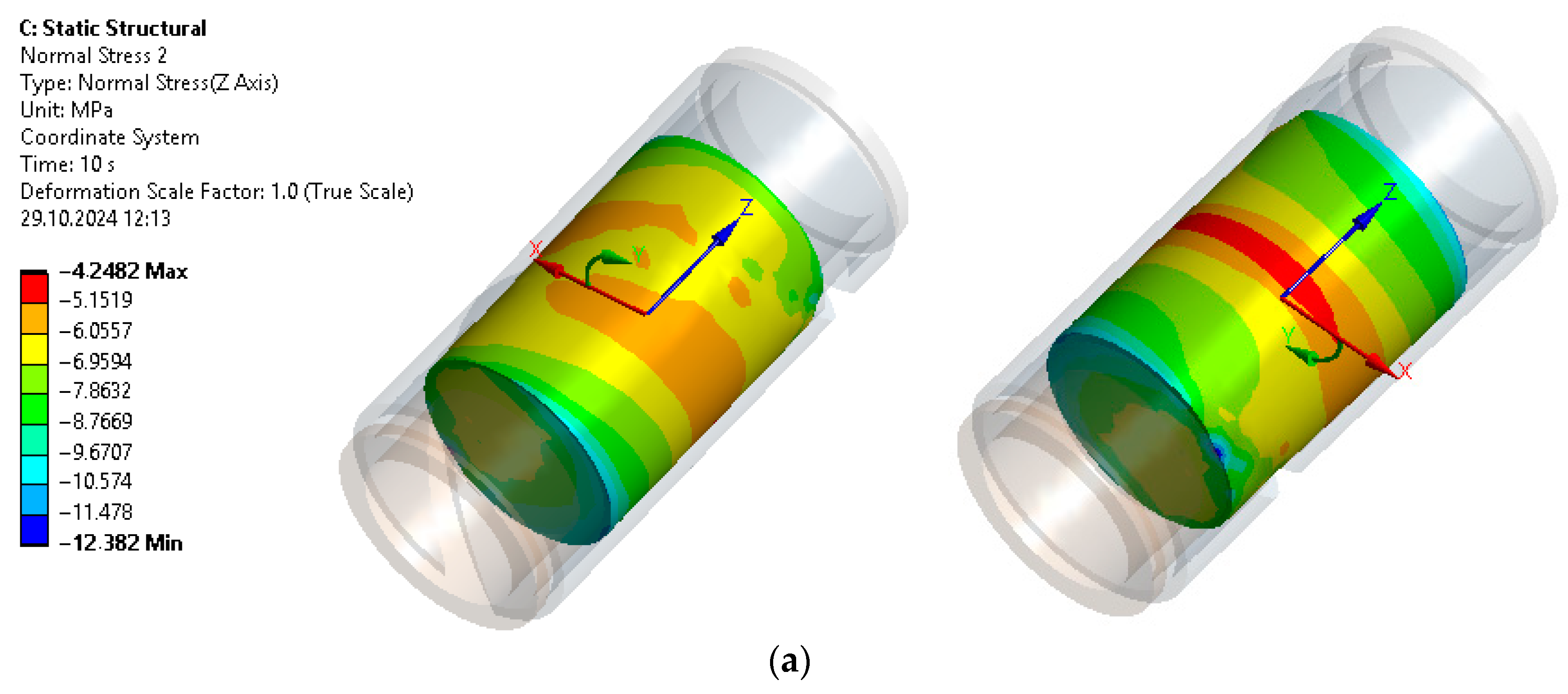
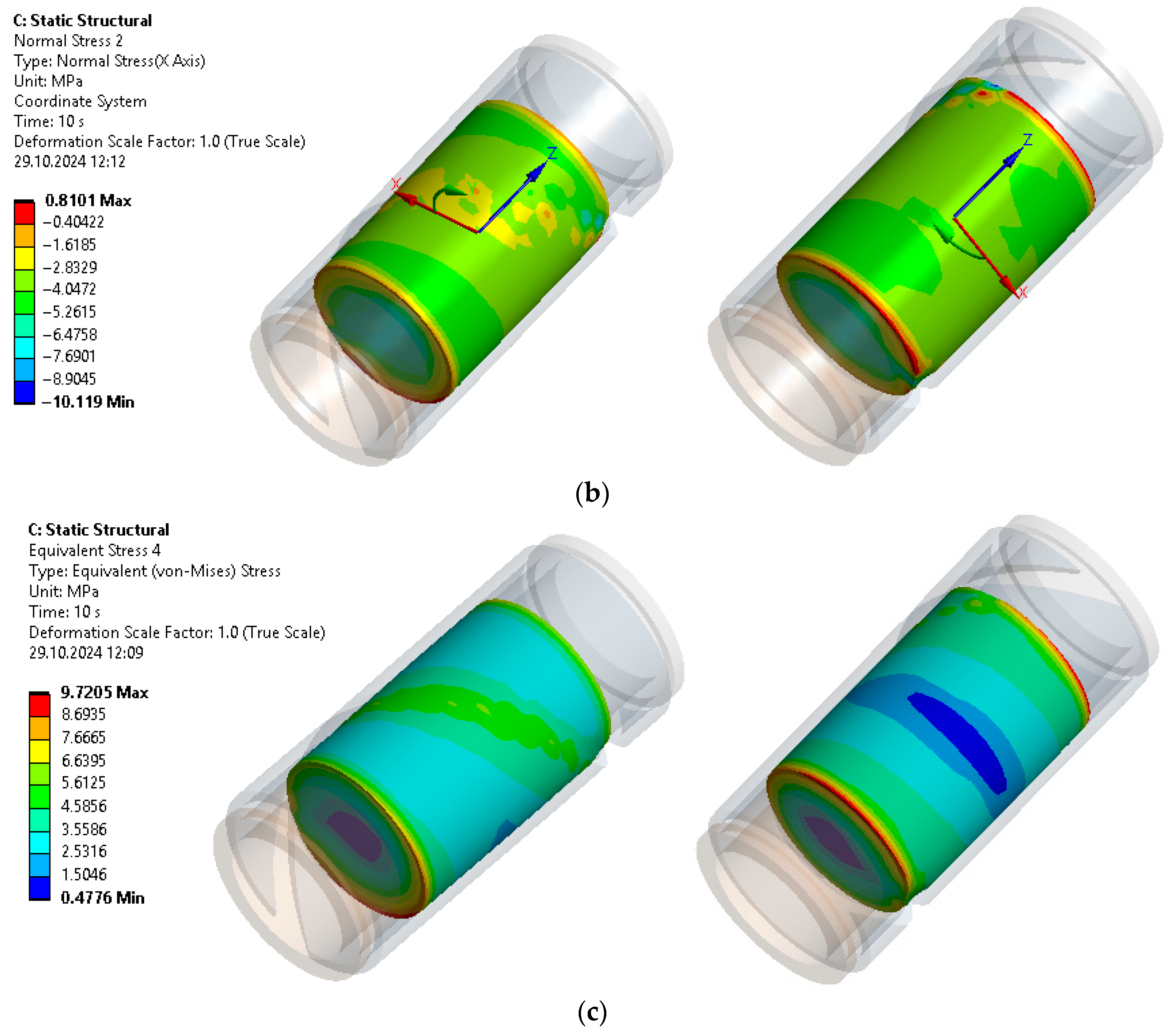
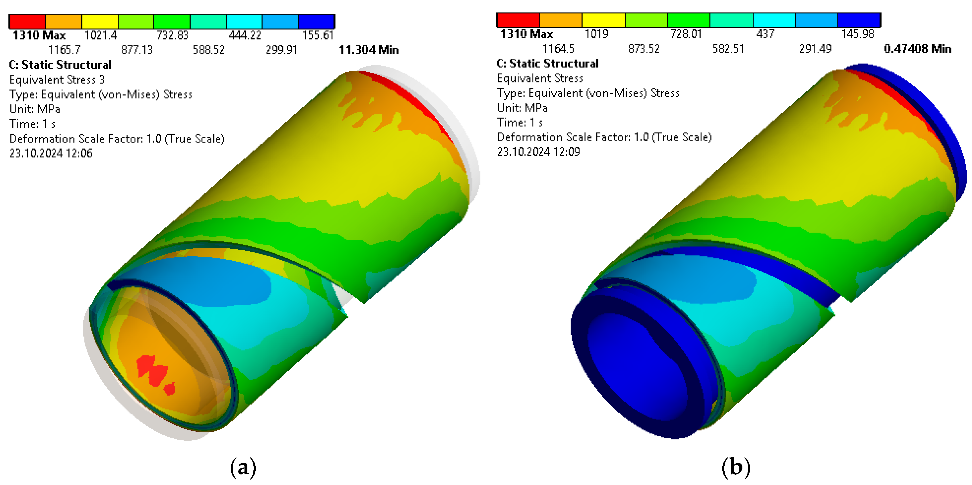
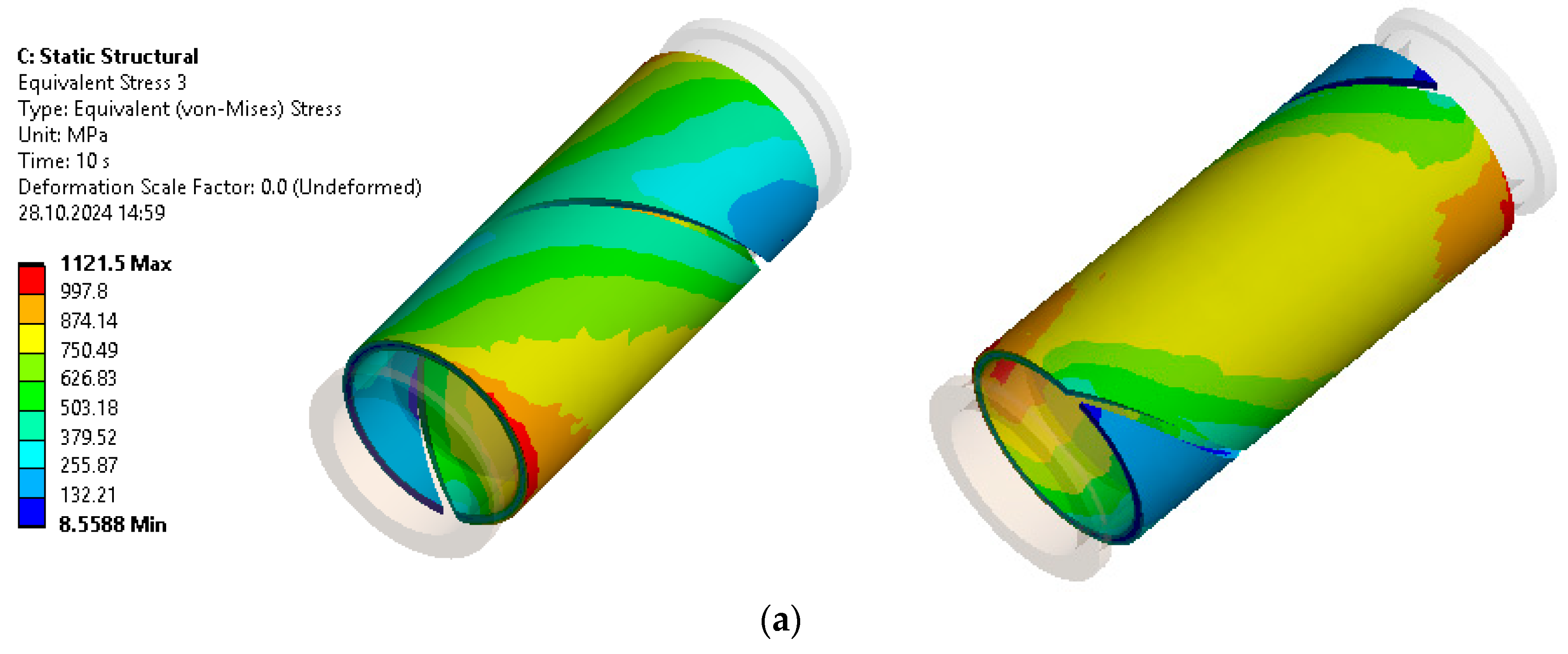
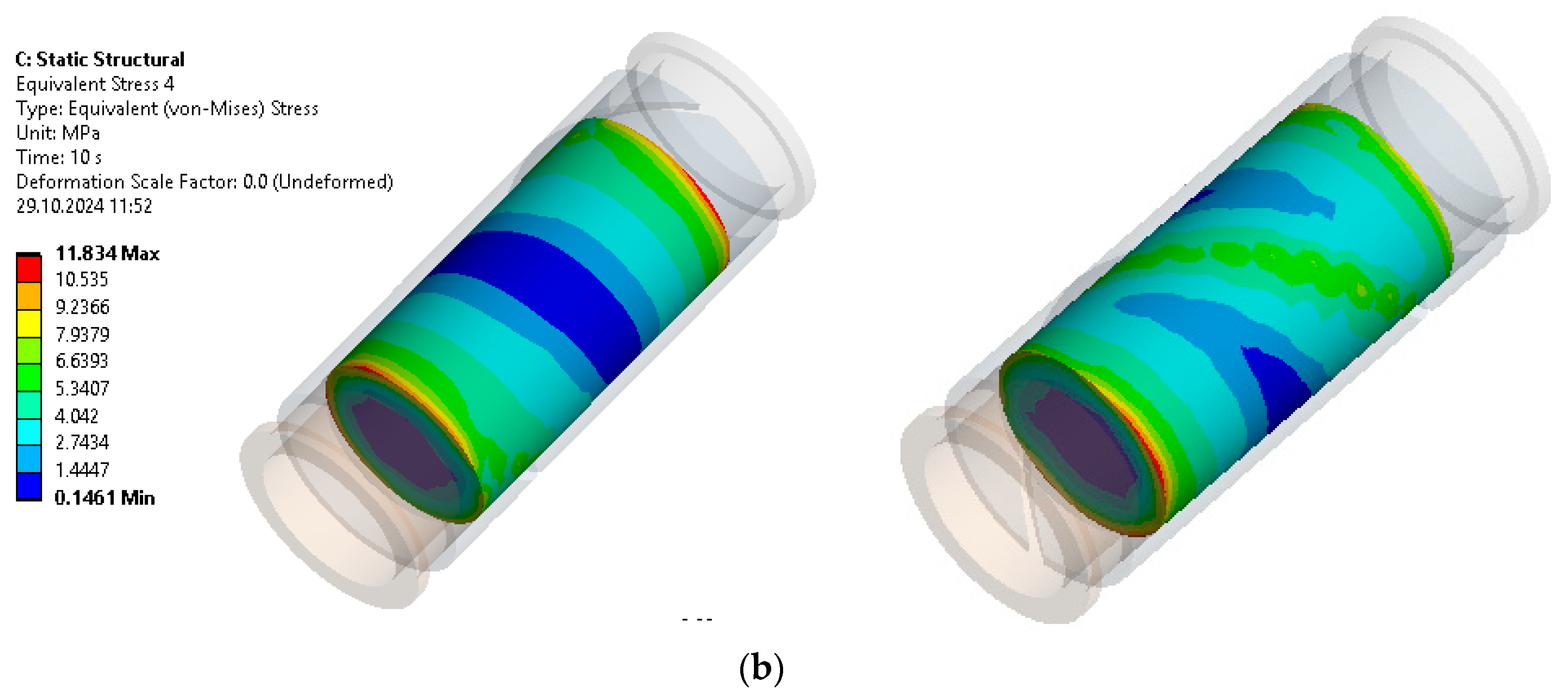
3.1. Stress State Analysis

We consider the stress state of the damper under an external load— P = 100     kN . Figure 4b–d show the chromograms of those components of the stress state that ultimately significantly affect the strength of the structure. The maximum absolute stress in the shell is the tensile circular stress σ Y that occurs on the inner surface of the shell (Figure 4b). It is localised in the area opposite the cut in the cross-sections belonging to the planes of the filler ends. When moving away from the filler end planes, the circular stresses decrease slightly, apparently due to a decrease in the contact pressure between the filler and the shell. On the outer surface of the shell, we observe compressive circular stresses. Their distribution pattern is similar to that of tensile circular stresses, but tensile circular stresses are predominant in absolute value.
The absolute values of axial normal stresses σ Z (Figure 4c) are significantly lower than the absolute values of circular normal stresses. The cut along the helical line contributes to an uneven distribution of stresses σ Z and causes a specific stress gradient along the length of the helix. The chromogram shows a gradual decrease in axial stresses towards the edges of the shell (including the edges of the cut). A cut along a cylindrical helical line contributes to the emergence of additional moments, resulting in stresses of different values on the chromogram σ Z . Figure 4d shows a chromogram of tangential stresses τ YZ . Other components of the tangential stress have significantly lower values. Tangential stresses are distributed asymmetrically along the perimeter of the shell cross-section. Compared to σ Y , maximum tangential stresses are distributed more evenly along the shell on both the inner and outer surfaces, and the stresses τ YZ reach the highest value, in contrast to σ Y , on the outer surface of the shell.
Next, let us analyse the stresses in the filler. In general, normal axial stresses in filler σ Zf reach their maximum (by modulus) values at the ends of the aggregate and gradually decrease in the direction of the cross-section equidistant from the ends (Figure 5a). It can be noted that stress concentration zones σ Zf appear near the pistons, as the pistons transfer the load directly into the filler material. The stresses σ Zf are not evenly distributed across the filler cross-section, with higher stresses (modulus) in the area where the filler is in contact with the solid part of the shell compared to the stresses in the area near the cut. In the central part of the filler, the normal axial stresses are lower and more evenly distributed across the cross-section. Radial stresses in the filler σ Xf arise as a result of contact with the shell, which deforms and creates a reaction to the surface of the filler (Figure 5b). The chromograms show an uneven distribution of radial stresses along the length of the filler due to friction, an uneven distribution along the filler’s vicinity due to the presence of a cut, and a transition zone along the cut. When the filler is compressed, the width of the cut increases, and the shell deforms outwards. This leads to lower σ Xf in areas close to the cut. Thus, in the areas coinciding with the cut, the radial stresses on the filler surface vary from a minimum value in the centre of the cut to higher values in the areas with a solid shell. At high loads, in some localised areas, we observe a complete breakdown of the contact between the shell and the filler. The analysis of Figure 5c shows that the highest equivalent stresses in the filler occur at the ends, while the central part of the length is subject to lower stresses. Due to the dry friction between the pusher and filler, on the surface of the filler ends, the equivalent stresses will be maximum at the periphery, where the combination of axial and tangential stresses creates peak values. Closer to the centre of the filler face, the equivalent stress values will decrease, reflecting the reduction in tangential stresses caused by friction.
Finally, we proceed to assess the strength of the bearing shell (Figure 6). The analysis of the built model showed that, under the operational load of the friction damper, most of the material of the filler and the open shell is in a complex stress state. Therefore, one of the strength theories should be used to estimate the strength. The equivalent stress according to the Huber–Mises theory indicates a combination of axial, radial, and tangential stresses and is an important indicator for assessing possible zones of plasticity. The peculiarities of the distribution of equivalent stresses (Figure 6) are mainly due to a combination of the effects of bending of the open shell and variable contact pressure along the length and around the shell. As can be seen from the chromogram, the maximum equivalent stress does not exceed the yield strength of the shell material, so the limit state is not reached at any point of the material.

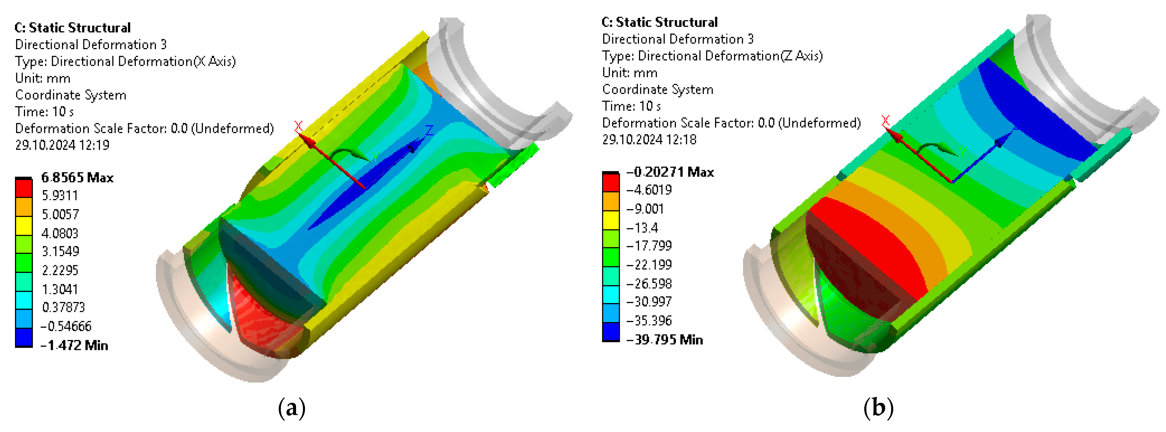
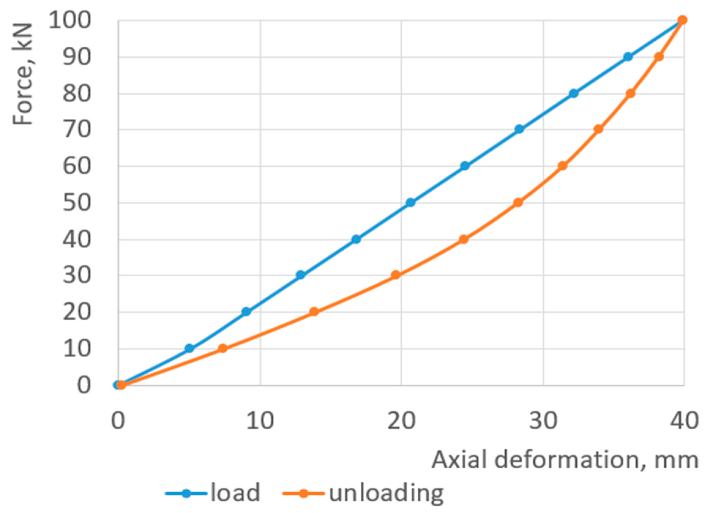
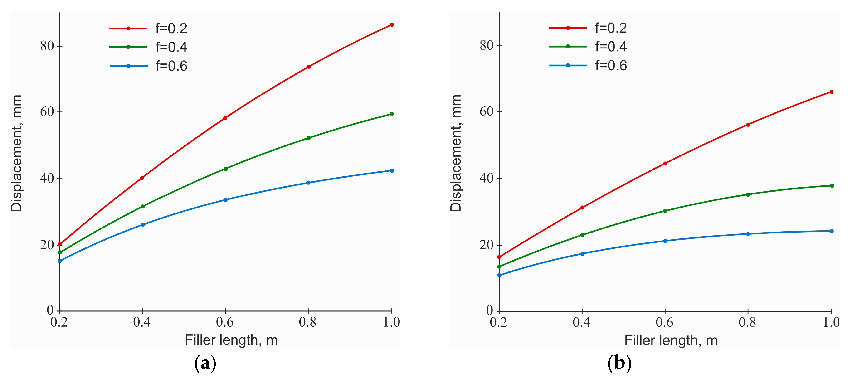
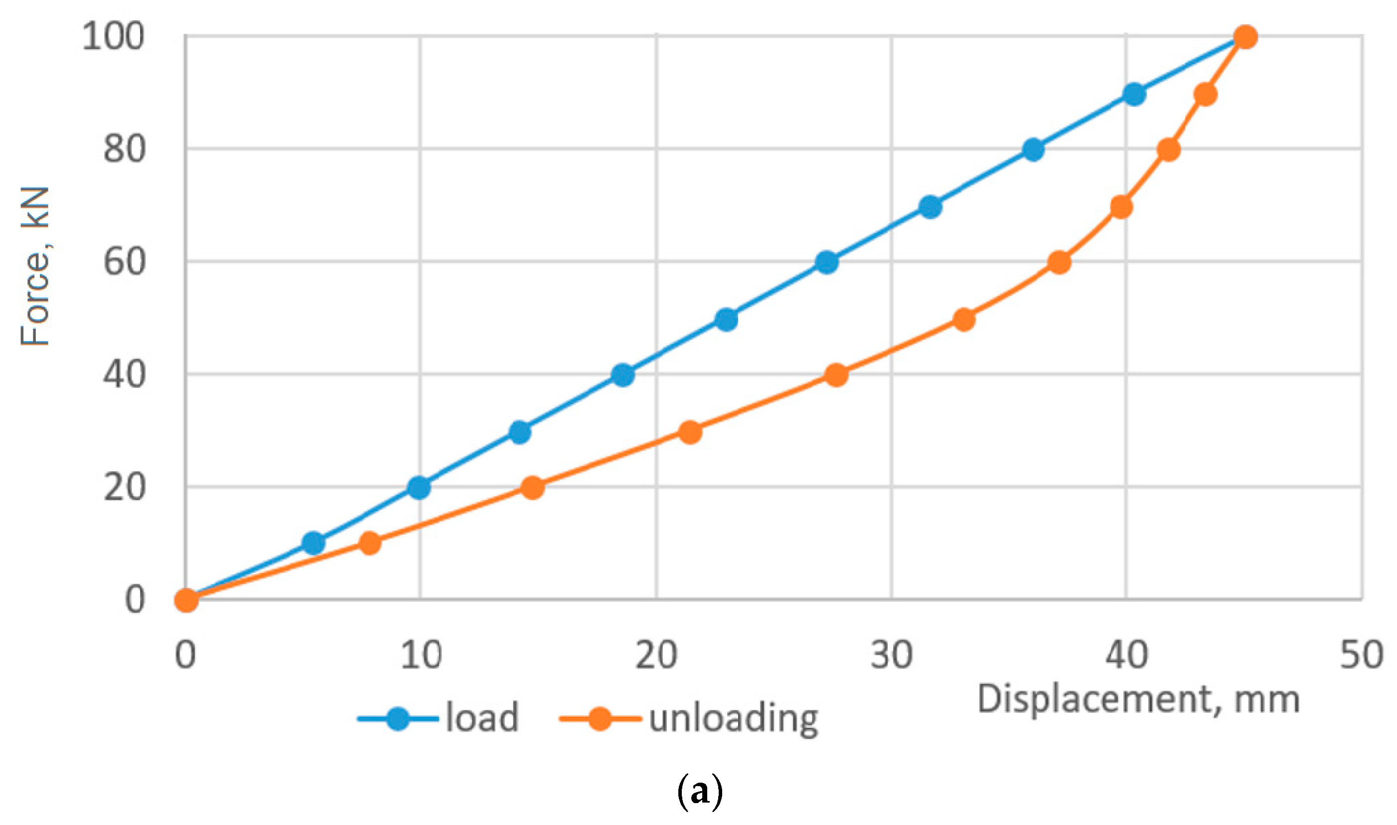
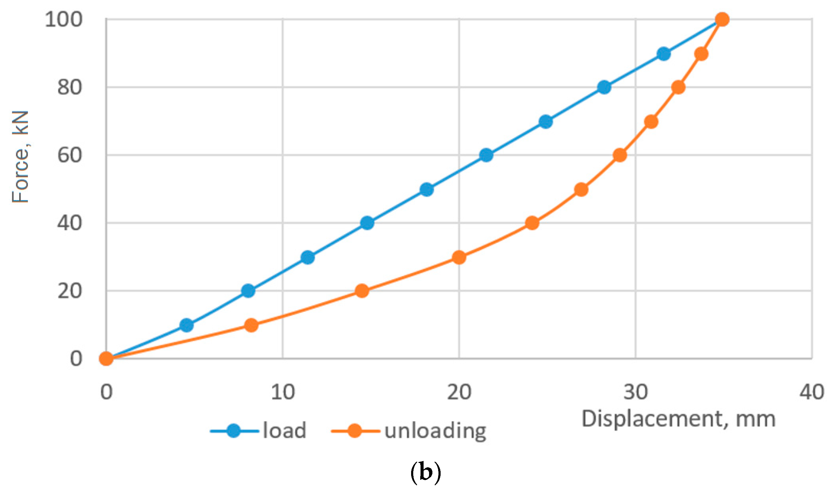
3.2. Displacement Analysis, Settlement-Load Diagram Construction

The distribution of axial and radial displacements in the system is significantly heterogeneous (Figure 7) and depends on a combination of the following factors: dry friction between the filler and the shell and between the filler and the pushers, deformable characteristics of the shell and the filler, and the presence of a helical cut in the shell. The analysis of the chromogram (Figure 7a) shows that the radial displacements increase from the axis of the device to the periphery, and the deformation of the open shell in the radial direction is non-axisymmetric. The maximum radial displacement in the damper was 6.9 mm. If we consider a typical cross-section of a shell with filler, the smallest radial displacements occur in the area of the shell cut. If we use a local coordinate system and count the azimuth from the section, the largest radial displacements will occur at an azimuth value close to ± 90 .
Figure 7b shows the distributions of axial displacements of the shell and filler. Recall that, in the model, the lower pusher of the damper is fixed, and the load is applied to the upper pusher. That is why, in Figure 7b, the axial displacement of the lower end of the filler approaches zero, and the displacement of the upper end corresponds to the total displacement of the damper—39.8 mm. At the same time, under the action of the load, both pushers symmetrically enter the shell, i.e., the shell has axial displacements not only due to deformation but also as a rigid whole. If this is taken into account, the shell stiffness in the direction of the generatrix is much higher than that of the filler, and attempts to change the friction coefficient had little effect on the rate of change in the axial displacements of the shell sections. As for the axial displacements of the filler, the dependence on friction is more evident. An increase in the coefficient of friction leads to an increase in the adhesion area (the area where there is no slippage in the longitudinal direction between the filler and the shell) and to a decrease in the overall displacement of the damper.
The external load P has been assumed to be constant or at least monotonically increasing. Now, let us analyse the structural hysteresis that occurs in a friction damper in response to an external non-monotonic load. In other words, it is necessary to construct a deformation diagram of the damper, which, given the known load history, can be used to predict the behaviour of the considered non-conservative system at any time after the start of the loading process, as well as to calculate the amount of energy dissipated during this process. The process of non-monotonic loading of the damper was studied in the quasi-static approximation. To analyse the results of this task, the typical colour interpretation of the friction damper displacements offered by the ANSYS post-processor is not sufficiently informative. Therefore, to construct the deformation diagram, we divided the loading range and unloading range into 10 intervals. At the boundaries of each loading (or unloading) interval, the results of solving the problem were read, which were used to build the diagram (Figure 8). Here, the abscissa axis shows the damper’s deflection, and the ordinate axis shows the value of the load applied to the upper pusher.
A hysteresis loop was formed on the force-settlement diagram of the pushers: during loading, the curve is initially nonlinear and then enters a straight line; when unloaded, it does not repeat the load trajectory; due to the presence of friction, the system seems to “hold” a certain residual deformation when the load is reduced, creating a hysteresis effect. The area of the constructed loop (Figure 8) is numerically equal to the losses of energy supplied to the damper during one loading and unloading cycle.
Figure 9 illustrates the effect of changing the value of the coefficient of friction of the filler—open shell and filler—and pusher pairs on the view of the friction damper deformation diagram. The diagram clearly shows the effect of increasing the stiffness of the damper with an increase in the coefficient of friction between the filler and the shell.
It is worth noting that, with an increase in the friction coefficient in the damper contact pairs, the maximum values of the stress components in the open shell decrease, while the stresses in the filler increase. In general, this effect is well illustrated by the chromograms of equivalent stresses in the shell (Figure 10a) and aggregate (Figure 10b), which can be compared with Figure 5c and Figure 6a, respectively.
Figure 11 shows the dependences of the shell damper pliability on the filler length for different shell thicknesses. Note that the filler length is equal to the operating length of the open shell. In general, with an increase in the length of the filler, the compliance of the damper increases, but this dependence is non-linear, and the following features can be traced. With an increase in the length of the system, the rate of increase in compliance gradually decreases, especially when the friction coefficient becomes larger.
This is because, due to friction, the contact pressure between the filler and the shell attenuates with distance from the ends of the filler. Thus, as the length of the damper increases, it turns out that the middle part of the shell works inefficiently. Therefore, an extensive increase in the length of the shell and filler is not a productive way to increase the compliance of the damper. The rate of increase in compliance slows down more quickly in dampers with a larger open-shell wall thickness.
A comparison of the graphical dependencies of Figure 11a,b indicates that, as the shell thickness increases, the compliance of the system decreases. In other identical conditions, a system with a lower coefficient of friction in contact pairs will have a higher compliance. An increase in the coefficient of friction leads to a decrease in the compliance of the elastic element.

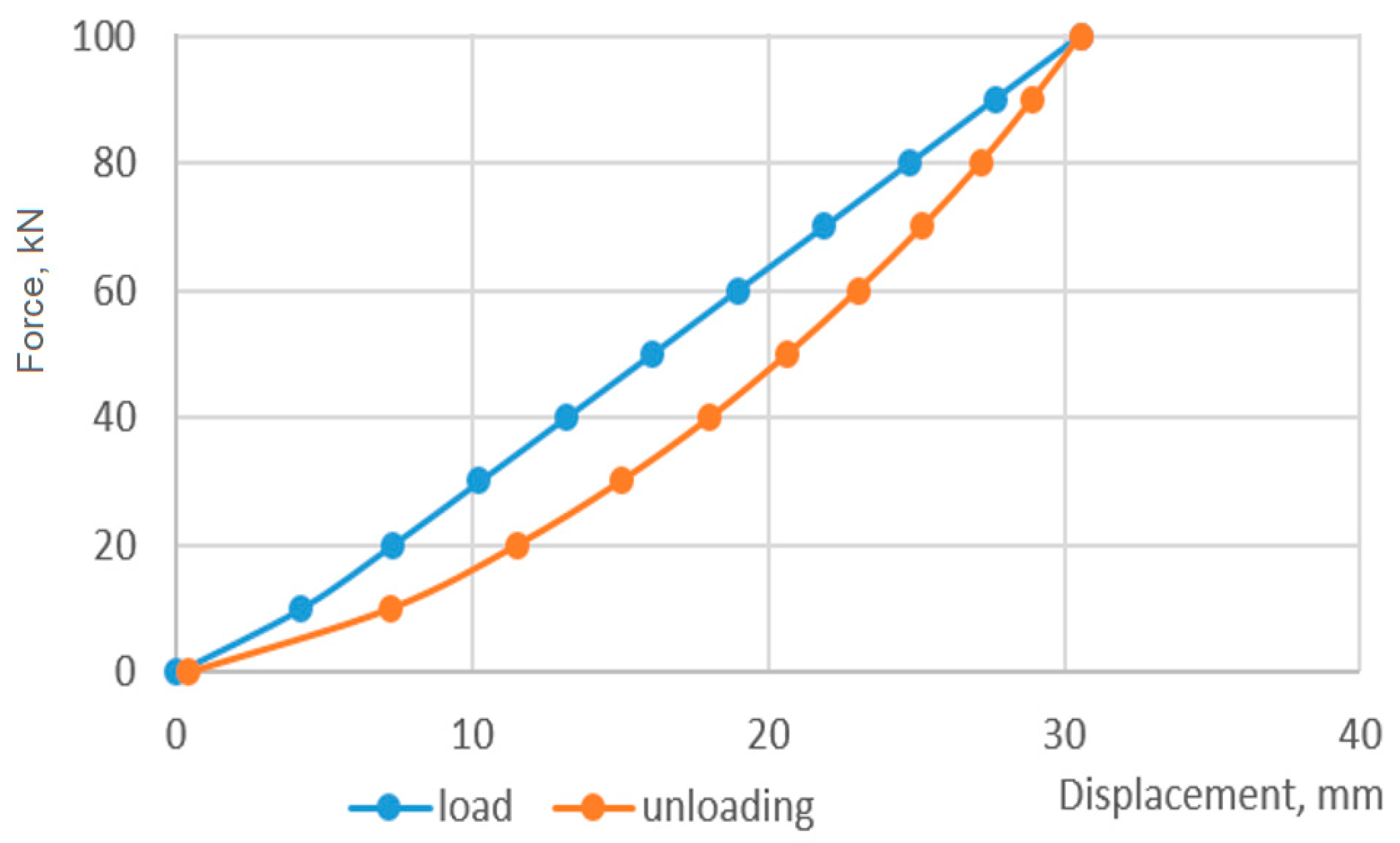
3.3. Comparison of the Stiffness of a Damper Based on a Shell with a Screw Cut with the Stiffness of a Basic Shell Damper Model

To evaluate the characteristics of the basic shell damper design (Figure 1), we made only one amendment to the finite element model, which was described in detail in Section 2.2. Instead of a cut along the helical line, the shell now has a vertical cut along the generatrix (Figure 12), and all other model parameters remained unchanged. Figure 13a,b show the deformation diagrams of the basic damper structure at different friction coefficients between the filler and the shell and pushers. As before, the diagrams show the damper settling on the abscissa axis and the load applied to the upper pusher on the ordinate axis. Qualitatively, the diagrams in Figure 13 do not differ significantly from the diagrams in Figure 8 and Figure 9. However, the quantitative analysis shows that the cut along the cylindrical helical line increases the stiffness of the damper and slightly reduces the amount of energy absorbed per load cycle.
A visualisation of the effect of changing the stiffness of the shell damper by changing the configuration of the shell cut is shown in Figure 14. Here, the load diagrams of the basic design of the shell damper (square labels) and the damper with a helical cut in the shell (triangular labels) are presented on the same graphical field. The red colour shows the cases when the system has a friction coefficient of 0.2, and the blue colour shows the cases when the friction coefficient is 0.4. When working in the range of high loads, the change in damper stiffness due to the change in the configuration of the cut reached 14%. Changes in the coefficient of friction in the damper contact pairs had little effect on this value, while for longer standard sizes, the change in stiffness was more noticeable. Therefore, in cases where the shell damper is operated under high loads and we have a strict limitation on the transverse dimension of the structure (for example, drilling shock absorbers), the proposed method of changing the stiffness can be recommended for implementation in practice.

4. Conclusions

Friction dampers based on dry friction effects are an important element of vibration protection systems due to their simplicity, efficiency, and ability to adapt to high loads. In this study, a new design of a shell friction damper was developed. The distinctive features of this design are as follows: the main bearing and actuating link of the damper is an open cylindrical shell, the cut of which is made along a helical line; the working body of the device is a weakly compressible elastic filler; contact interaction of the filler with the shell allows for full use of the bending effects of the open shell; the presence of dry friction on the contact surfaces provides damping properties of the structure, the quantitative parameters of which are formed mainly due to structural damping.
A finite element model of the designed damper was built. Each component was modelled as a separate array of finite elements, and the contact interaction of the surfaces of the damper components was modelled as a one-way contact with consideration of dry friction, which allowed for us to realistically simulate the behaviour of the device.
Using the developed model, solutions to the non-conservative contact problem on the frictional interaction of the deformable filler with the pushers and the shell cut along the helical line were obtained. As a result, the strength, stiffness, and damping characteristics of the developed damper were evaluated.
The hypothesis that, other things being equal, a change in the configuration of the shell cut from vertical (along the generatrix) to helical (along a cylindrical helical line) will be accompanied by an increase in the damper stiffness is confirmed. It was found that a change in the coefficient of friction in the contact pairs has little impact on this effect, while an increase in the damper dimensions enhances it.
The authors associate further research with industrial testing of the shell damper as a component of drilling shock absorbers.

Author Contributions

Conceptualisation, A.V.; methodology, A.V., V.M. and A.A.; software, V.M.; validation, A.V. and V.M.; formal analysis, A.A.; investigation, A.V.; resources, V.M.; data curation, A.V., V.M. and A.A.; writing—original draft preparation, A.V.; writing—review and editing, A.V. and V.M.; visualisation, A.V. and A.A.; supervision, V.M. and A.A.; project administration, A.V.; funding acquisition, A.V. All authors have read and agreed to the published version of the manuscript.

Funding

This research received no targeted external funding.

Institutional Review Board Statement

Not applicable.

Informed Consent Statement

Not applicable.

Data Availability Statement

The data are contained within this article. Further inquiries can be directed to the corresponding author.

Conflicts of Interest

The authors declare no conflicts of interest.

References

  1. Aydin, E.; Ozturk, B.; Dutkiewicz, M. Analysis of efficiency of passive dampers in multistorey buildings. J. Sound Vib. 2019, 439, 17–28. [Google Scholar] [CrossRef]
  2. Zhao, Q.; Tan, Y.; Sun, M.; Jiang, Y.; Wang, P.; Meng, F.; Li, Z. Performance of Strengthened Accelerated Oscillator Damper for Vibration Control of Bridges. Appl. Sci. 2024, 14, 6732. [Google Scholar] [CrossRef]
  3. Wang, Z.; Liu, C.; Zheng, X.; Zhao, L.; Qiu, Y. Advancements in Semi-Active Automotive Suspension Systems with Magnetorheological Dampers: A Review. Appl. Sci. 2024, 14, 7866. [Google Scholar] [CrossRef]
  4. Machado, M.R.; Dutkiewicz, M. Wind turbine vibration management: An integrated analysis of existing solutions, products, and Open-source developments. Energy Rep. 2024, 11, 3756–3791. [Google Scholar] [CrossRef]
  5. Kang, C.-H.; Park, H.-S.; Seo, S.-W.; Kwag, D.-G. Design and Experiment of a Passive Vibration Isolator for Small Unmanned Aerial Vehicles. Appl. Sci. 2024, 14, 4113. [Google Scholar] [CrossRef]
  6. Gasparetto, V.E.L.; Reid, J.; ElSayed, M.S.A. Passive-Tuned Mass Dampers for the Pointing Accuracy Mitigation of VLBI Earth-Based Antennae Subject to Aerodynamic Gust. Appl. Mech. 2023, 4, 816–840. [Google Scholar] [CrossRef]
  7. El Ouni, M.H.; Abdeddaim, M.; Elias, S.; Kahla, N.B. Review of Vibration Control Strategies of High-Rise Buildings. Sensors 2022, 22, 8581. [Google Scholar] [CrossRef]
  8. Velichkovich, A.S.; Velichkovich, S.V. Vibration-impact damper for controlling the dynamic drillstring conditions. Chem. Pet. Eng. 2001, 37, 213–215. [Google Scholar] [CrossRef]
  9. Zhang, R.; Wang, X.; John, S. A Comprehensive Review of the Techniques on Regenerative Shock Absorber Systems. Energies 2018, 11, 1167. [Google Scholar] [CrossRef]
  10. Jacob, K.; Tan, A.S.; Sattel, T.; Kohl, M. Enhancement of Shock Absorption Using Hybrid SMA-MRF Damper by Complementary Operation. Actuators 2022, 11, 280. [Google Scholar] [CrossRef]
  11. Velichkovich, A.S.; Dalyak, T.M. Assessment of stressed state and performance characteristics of jacketed spring with a cut for drill shock absorber. Chem. Pet. Eng. 2015, 51, 188–193. [Google Scholar] [CrossRef]
  12. Ehlers, T.; Tatzko, S.; Wallaschek, J.; Lachmayer, R. Design of particle dampers for additive manufacturing. Addit. Manuf. 2021, 38, 101752. [Google Scholar] [CrossRef]
  13. Pang, F.; Sun, S.; Liu, W.; Zhang, G. Research on reliability test method of MR damper based on damage equivalent. Vibroengin. Procedia 2022, 44, 33–39. [Google Scholar] [CrossRef]
  14. Pei, Y.; Liu, Z.; Xu, J.; Qi, B.; Cheng, Q. Grouping Preventive Maintenance Strategy of Flexible Manufacturing Systems and Its Optimization Based on Reliability and Cost. Machines 2023, 11, 74. [Google Scholar] [CrossRef]
  15. Zoccolini, L.; Bruschi, E.; Cattaneo, S.; Quaglini, V. Current Trends in Fluid Viscous Dampers with Semi-Active and Adaptive Behavior. Appl. Sci. 2023, 13, 10358. [Google Scholar] [CrossRef]
  16. Zhang, Y.; Xu, W.; Wang, S.; Du, D.; Geng, Y. Mechanical Modeling of Viscous Fluid Damper with Temperature and Pressure Coupling Effects. Machines 2024, 12, 366. [Google Scholar] [CrossRef]
  17. Chen, Y.; Qin, C.; Zhou, H.; Xu, Z.; Xu, A.; Li, H. Damping Characteristics of a Novel Bellows Viscous Damper. Sensors 2024, 24, 6265. [Google Scholar] [CrossRef] [PubMed]
  18. Kluczyk, M.; Grządziela, A.; Pająk, M.; Muślewski, Ł.; Szeleziński, A. The Fatigue Wear Process of Rubber-Metal Shock Absorbers. Polymers 2022, 14, 1186. [Google Scholar] [CrossRef] [PubMed]
  19. Tang, N.; Rongong, J.A.; Sims, N.D. Design of adjustable Tuned Mass Dampers using elastomeric O-rings. J. Sound Vib. 2018, 433, 334–348. [Google Scholar] [CrossRef]
  20. Liu, Y.; Liu, J.; Pan, G.; Huang, Q. Modeling and analysis of a metal rubber vibration isolation system considering the nonlinear stiffness characteristics. Rev. Sci. Instrum. 2023, 94, 015105. [Google Scholar] [CrossRef] [PubMed]
  21. Landar, S.; Velychkovych, A.; Mykhailiuk, V. Numerical and analytical models of the mechanism of torque and axial load transmission in a shock absorber for drilling oil, gas and geothermal wells. Eng. Solid Mech. 2024, 12, 207–220. [Google Scholar] [CrossRef]
  22. Jung, H.-Y.; Kim, I.-H.; Jung, H.-J. Feasibility Study of the Electromagnetic Damper for Cable Structures Using Real-Time Hybrid Simulation. Sensors 2017, 17, 2499. [Google Scholar] [CrossRef]
  23. She, C.; Zhang, M.; Ge, Y.; Tang, L.; Yin, H.; Peng, G. Design and Simulation Analysis of an Electromagnetic Damper for Reducing Shimmy in Electrically Actuated Nose Wheel Steering Systems. Aerospace 2022, 9, 113. [Google Scholar] [CrossRef]
  24. Makowski, M.; Knap, L. Study of a Controlled Piezoelectric Damper. Sensors 2021, 21, 3509. [Google Scholar] [CrossRef]
  25. Chatziathanasiou, G.M.; Chrysochoidis, N.A.; Rekatsinas, C.S.; Saravanos, D.A. A semi-active shunted piezoelectric tuned-mass-damper for multi-modal vibration control of large flexible structures. J. Sound Vib. 2022, 537, 117222. [Google Scholar] [CrossRef]
  26. Viadero-Monasterio, F.; Meléndez-Useros, M.; Jiménez-Salas, M.; Boada, B.L. Robust Static Output Feedback Control of a Semi-Active Vehicle Suspension Based on Magnetorheological Dampers. Appl. Sci. 2024, 14, 10336. [Google Scholar] [CrossRef]
  27. Sapiński, B.; Jastrzębski, Ł. Performance Improvement of an MR-Damper-Based Vibration-Reduction System with Energy Harvesting at Sprung Mass Changes. Energies 2024, 17, 3436. [Google Scholar] [CrossRef]
  28. Hao, J.; Wang, Y.; Peng, Y.; Ma, H.; Wei, X. Design and Structure Optimization of Arresting Gear Based on Magnetorheological Damper. Aerospace 2023, 10, 1019. [Google Scholar] [CrossRef]
  29. Wang, H.; Bi, C.; Liu, W.; Zhou, F. Squeeze Behaviors of Magnetorheological Fluids under Different Compressive Speeds. Materials 2023, 16, 3109. [Google Scholar] [CrossRef] [PubMed]
  30. Gagnon, L.; Morandini, M.; Ghiringhelli, G.L. A review of friction damping modeling and testing. Arch. Appl. Mech. 2020, 90, 107–126. [Google Scholar] [CrossRef]
  31. Ma, H.Y.; Li, L.; Wu, Y.G.; Fan, Y.; Gao, Q. Design of dry friction dampers for thin-walled structures by an accelerated dynamic Lagrange method. J. Sound Vib. 2020, 489, 115550. [Google Scholar] [CrossRef]
  32. Mandziy, T.; Ivasenko, I.; Berehulyak, O.; Vorobel, R.; Bembenek, M.; Kryshtopa, S.; Ropyak, L. Evaluation of the Degree of Degradation of Brake Pad Friction Surfaces Using Image Processing. Lubricants 2024, 12, 172. [Google Scholar] [CrossRef]
  33. Jaisee, S.; Yue, F.; Ooi, Y.H. A state-of-the-art review on passive friction dampers and their applications. Eng. Struct. 2021, 235, 112022. [Google Scholar] [CrossRef]
  34. Balaji, P.S.; Karthik SelvaKumar, K. Applications of Nonlinearity in Passive Vibration Control: A Review. J. Vib. Eng. Technol. 2021, 9, 183–213. [Google Scholar] [CrossRef]
  35. Yuan, J.; Gastaldi, C.; Goy, E.D.; Chouvion, B. Friction damping for turbomachinery: A comprehensive review of modelling, design strategies, and testing capabilities. Prog. Aerosp. Sci. 2024, 147, 101018. [Google Scholar] [CrossRef]
  36. Baraftabi, E.S.; Elizei, M.H.; Esmaeilabadi, R. Numerical and experimental investigation of a new model of friction damper in diagonal brace under cyclic loading. Structures 2024, 61, 105830. [Google Scholar] [CrossRef]
  37. Velichkovich, A.S. Shock Absorber for Oil-Well Sucker-Rod Pumping Unit. Chem. Petrol. Eng. 2005, 41, 544–546. [Google Scholar] [CrossRef]
  38. Rathee, R. Numerical modeling and simulation of friction models for mechanical systems: A brief review. Mater. Today Proc. 2023; in press. [Google Scholar] [CrossRef]
  39. Barsotti, R.; Bennati, S.; Migliaccio, G. Non-Linear Dynamics of Simple Elastic Systems Undergoing Friction-Ruled Stick–Slip Motions. CivilEng 2024, 5, 420–434. [Google Scholar] [CrossRef]
  40. Dou, C.; Fan, J.; Li, C.; Cao, J.; Gao, M. On discontinuous dynamics of a class of friction-influenced oscillators with nonlinear damping under bilateral rigid constraints. Mech. Mach. Theory 2020, 147, 103750. [Google Scholar] [CrossRef]
  41. Ferrotto, M.F.; Cavaleri, L. Variable Friction Dampers (VFD) for a modulated mitigation of the seismic response of framed structures: Characteristics and design criteria. Probabilistic Eng. Mech. 2022, 70, 103375. [Google Scholar] [CrossRef]
  42. Mrad, C.; Titirla, M.; Larbi, W. Optimal Design of Viscous and Friction Dampers in Symmetric Reinforced Concrete Buildings. In Proceedings of the 7th World Congress on Civil, Structural, and Environmental Engineering, Lisbon, Portugal, 10–12 April 2022. [Google Scholar] [CrossRef]
  43. Wang, Q.; Shen, H.; Zhang, Z.; Qian, H. Mechanical Behaviors of a Buckling-Plate Self-Centering Friction Damper. Buildings 2023, 13, 440. [Google Scholar] [CrossRef]
  44. Guglielmino, E.; Edge, K.A. A controlled friction damper for vehicle applications. Control. Eng. Pract. 2004, 12, 431–443. [Google Scholar] [CrossRef]
  45. Dixon, J.C. The Shock Absorber Handbook, 2nd ed.; John Wiley & Sons, Ltd.: Hoboken, NJ, USA, 2007. [Google Scholar] [CrossRef]
  46. Sun, Y.; Denimal, E.; Yuan, J.; Salles, L. Geometric design of friction ring dampers in blisks using nonlinear modal analysis and Kriging surrogate model. Struct. Multidiscip. Optim. 2022, 65, 98. [Google Scholar] [CrossRef]
  47. Velichkovich, A.S. Design features of shell springs for drilling dampers. Chem. Petrol. Eng. 2007, 43, 458–461. [Google Scholar] [CrossRef]
  48. Velichkovich, A.; Dalyak, T.; Petryk, I. Slotted shell resilient elements for drilling shock absorbers. Oil Gas Sci. Technol. Rev. IFP Energ. Nouv. 2018, 73, 34. [Google Scholar] [CrossRef]
  49. Bembenek, M.; Grydzhuk, Y.; Gajdzik, B.; Ropyak, L.; Pashechko, M.; Slabyi, O.; Al-Tanakchi, A.; Pryhorovska, T. An Analytical–Numerical Model for Determining “Drill String–Wellbore” Frictional Interaction Forces. Energies 2024, 17, 301. [Google Scholar] [CrossRef]
  50. Man, J.; Xue, B.; Bian, X.; Yan, W.; Qiao, D.; Zeng, W. Experimental and Numerical Investigations on the Dynamic Response of Blades with Dual Friction Dampers. Aerospace 2023, 10, 977. [Google Scholar] [CrossRef]
  51. Bruschi, E.; Quaglini, V. Assessment of Non-Linear Analyses of RC Buildings Retrofitted with Hysteretic Dampers According to the Italian Building Code. Appl. Sci. 2024, 14, 2684. [Google Scholar] [CrossRef]
  52. Lozynskyi, V.; Shihab, T.; Drach, I.; Ropyak, L. The Inertial Disturbances of Fluid Movement in the Chamber of a Liquid Autobalancer. Machines 2024, 12, 39. [Google Scholar] [CrossRef]
  53. Prysyazhnyuk, P.; Bembenek, M.; Drach, I.; Korzhov, A.; Romanyshyn, L.; Ropyak, L. Restoration of the Impact Crusher Rotor Using FCAW with High-Manganese Steel Reinforced by Complex Carbides. Manag. Syst. Prod. Eng. 2024, 32, 294–302. [Google Scholar] [CrossRef]
  54. Wahad, H.S.; Tudor, A.; Vlase, M.; Cerbu, N.; Subhi, K.A. The effect of friction in coulombian damper. IOP Conf. Ser. Mater. Sci. Eng. 2017, 174, 012021. [Google Scholar] [CrossRef]
  55. Shopa, V.M.; Shatskii, I.P.; Popadyuk, I.I. Elementary calculation of structural damping in shell springs. Sov. Eng. Res. 1989, 9, 42–44. [Google Scholar]
  56. Bedzir, A.A.; Shatskii, I.P.; Shopa, V.M. Nonideal contact in a composite shell structure with a deformable filler. Int. Appl. Mech. 1995, 31, 351–354. [Google Scholar] [CrossRef]
  57. Herisanu, N.; Marinca, V. Analytical Study of Nonlinear Vibration in a Rub-Impact Jeffcott Rotor. Energies 2021, 14, 8298. [Google Scholar] [CrossRef]
  58. Gao, S.; Wang, Y. An Evaluation Method for Dry Friction Damping of Ring Damper in Gas Turbine Engines under Axial Vibration. Aerospace 2021, 8, 302. [Google Scholar] [CrossRef]
  59. Horvath, H.Z.; Takacs, D. Numerical Analysis on Shimmying Wheels with Dry Friction Damper. Period. Polytech. Mech. Eng. 2023, 67, 118–126. [Google Scholar] [CrossRef]
  60. Huang, Z.; Tan, J.; Liu, C.; Lu, X. Dynamic Characteristics of a Segmented Supercritical Driveline with Flexible Couplings and Dry Friction Dampers. Symmetry 2021, 13, 281. [Google Scholar] [CrossRef]
  61. Man, J.; Bian, X.; Zeng, W.; Yan, W.; Qiao, D. Experimental Investigation of the Dynamic Response of a Flat Blade with Dual Dry Friction Dampers. Energies 2023, 16, 7401. [Google Scholar] [CrossRef]
  62. Wu, Y.G.; Fan, L.; Li, Y.; Ma, H.Y.; Wang, W.J.; Christen, J.-L.; Ichchou, M. Design of semi-active dry friction dampers for steady-state vibration: Sensitivity analysis and experimental studies. J. Sound Vib. 2019, 459, 114850. [Google Scholar] [CrossRef]
  63. Velichkovich, A.S.; Popadyuk, I.I.; Shopa, V.M. Experimental study of shell flexible component for drilling vibration damping devices. Chem. Pet. Eng. 2011, 46, 518–524. [Google Scholar] [CrossRef]
  64. Deng, P.; Tan, X.; Bai; Li, H. Influence of Blades’ Shape and Cutters’ Arrangement of PDC Drill Bit on Nonlinear Vibration of Deep Drilling System. J. Sound Vib. 2023, 572, 118165. [Google Scholar] [CrossRef]
  65. Ropyak, L.Y.; Pryhorovska, T.O.; Levchuk, K.H. Analysis of materials and modern technologies for PDC drill bit manufacturing. Prog. Phys. Met. 2020, 21, 274–301. [Google Scholar] [CrossRef]
  66. Li, L.; Zhang, C.; Wu, A. Study on Mechanism of Stick–Slip Vibration Based on Torque Characteristics of PDC Bit. Appl. Sci. 2024, 14, 6419. [Google Scholar] [CrossRef]
  67. Shatskii, I.P.; Perepichka, V.V. Shock-wave propagation in an elastic rod with a viscoplastic external resistance. J. Appl. Mech. Tech. Phys. 2013, 54, 1016–1020. [Google Scholar] [CrossRef]
  68. Dutkiewicz, M.; Velychkovych, A.; Andrusyak, A.; Petryk, I.; Kychma, A. Analytical Model of Interaction of an Oil Pipeline with a Support of an Overpass Built in a Mountainous Area. Energies 2023, 16, 4464. [Google Scholar] [CrossRef]
  69. Shatskyi, I.; Perepichka, V. Problem of dynamics of an elastic rod with decreasing function of elastic-plastic external resistance. In Dynamical Systems in Applications, Proceedings of the DSTA 2017, Lodz, Poland, 11–14 December 2017; Awrejcewicz, J., Ed.; Springer: Cham, Switzerland, 2018; Volume 249, pp. 335–342. [Google Scholar] [CrossRef]
  70. Yue, F.; Wu, Z. Fracture Mechanical Analysis of Thin-Walled Cylindrical Shells with Cracks. Metals 2021, 11, 592. [Google Scholar] [CrossRef]
  71. Shats’kyi, I.P. Closure of a longitudinal crack in a shallow cylindrical shell in bending. Mater. Sci. 2005, 41, 186–191. [Google Scholar] [CrossRef]
  72. Zhu, Y.; Yang, J.; Pan, H. Three-Dimension Crack Propagation Behavior of Conical-Cylindrical Shell. Metals 2023, 13, 698. [Google Scholar] [CrossRef]
  73. Shats’kyi, I.P.; Makoviichuk, M.V. Analysis of the limiting state of cylindrical shells with cracks with regard for the contact of crack lips. Strength Mater. 2009, 41, 560–565. [Google Scholar] [CrossRef]
  74. Shatskii, I.P.; Makoviichuk, N.V. Effect of closure of collinear cracks on the stress-strain state and the limiting equilibrium of bent shallow shells. J. Appl. Mech. Tech. Phys. 2011, 52, 464–470. [Google Scholar] [CrossRef]
  75. Nobili, A.; Radi, E.; Lanzoni, L. A cracked infinite Kirchhoff plate supported by a two-parameter elastic foundation. J. Eur. Ceram. Soc. 2014, 34, 2737–2744. [Google Scholar] [CrossRef]
  76. Tutko, T.; Dubei, O.; Ropyak, L.; Vytvytskyi, V. Determination of Radial Displacement Coefficient for Designing of Thread Joint of Thin-Walled Shells. In Advances in Design, Simulation and Manufacturing IV, Proceedings of the 4th International Conference on Design, Simulation, Manufacturing: The Innovation Exchange, DSMIE 2021, Lviv, Ukraine, 8–11 June 2021; Ivanov, V., Trojanowska, J., Pavlenko, I., Zajac, J., Peraković, D., Eds.; Lecture Notes in Mechanical Engineering; Springer: Cham, Switzerland, 2021; pp. 153–162. [Google Scholar] [CrossRef]
  77. Awrejcewicz, J.; Olejnik, P. Analysis of Dynamic Systems with Various Friction Laws. ASME. Appl. Mech. Rev. 2005, 58, 389–411. [Google Scholar] [CrossRef]
  78. Velychkovych, A. Numerical model of interation of package of open shells with a weakly compressible filler in a friction shock absorber. Eng. Solid Mech. 2022, 10, 287–298. [Google Scholar] [CrossRef]
  79. Lu, S.; Liu, J.; Hekkenberg, R. Mesh Properties for RANS Simulations of Airfoil-Shaped Profiles: A Case Study of Rudder Hydrodynamics. J. Mar. Sci. Eng. 2021, 9, 1062. [Google Scholar] [CrossRef]
  80. Stolarski, T.; Nakasone, Y.; Yoshimoto, S. Application of ANSYS to contact between machine elements. Eng. Anal. ANSYS Softw. 2018, 2018, 375–509. [Google Scholar] [CrossRef]
  81. Sabri, L.A.; Stojanović, N.; Senatore, A.; Jweeg, M.J.; Abed, A.M.; Abdullah, O.I. Three-Dimensional Finite Element Analysis of Contact Problem in Dry Friction Clutches. Lubricants 2021, 9, 115. [Google Scholar] [CrossRef]
  82. Mattei, L.; Di Puccio, F. Frictionless vs. Frictional Contact in Numerical Wear Predictions of Conformal and Non-conformal Sliding Couplings. Tribol. Lett. 2022, 70, 115. [Google Scholar] [CrossRef]
Figure 1. Shell damper: (a)—experimental samples; (b)—conceptual diagram of the damper; 1 and 4—upper and lower pushers, 2—a cylindrical shell with a cut along the generatrix, 3—weakly compressible filler.
Applmech 06 00001 g001
Figure 2. Friction damper with an open shell cut along a cylindrical helical line: (a)—experimental samples; (b)—schematic diagram; 1 and 4—upper and lower pushers, 2—open cylindrical shell, 3—weakly compressible deformable filler, 5—cut along a cylindrical helical line.
Applmech 06 00001 g002
Figure 3. Design scheme of the friction damper (a); finite element model of the damper (b) and its individual parts (c).
Applmech 06 00001 g003aApplmech 06 00001 g003b
Figure 4. Investigation of the stress state of the damper shell, which is cut along a cylindrical helical line (external load on the pusher is 100 kN): (a)—reference of the cylindrical coordinate system; (b)—chromogram of circular stresses; (c)—chromogram of axial normal stresses; (d)—chromogram of tangential stresses.
Applmech 06 00001 g004
Figure 5. Investigation of the main components of the stress state and equivalent stresses in the filler (external load on the pusher of 100 kN): (a)—chromograms of axial normal stresses; (b)—chromograms of radial normal stresses; (c)—chromogram of equivalent stresses calculated by the Huber–Mises theory.
Applmech 06 00001 g005aApplmech 06 00001 g005b
Figure 6. Strength assessment of a friction damper in terms of equivalent stresses (external load on the pusher 100 kN): (a)—open shell, cut along a cylindrical helical line; (b)—shell damper.
Applmech 06 00001 g006
Figure 7. Displacement chromograms of the damper: (a)—radial displacement, (b)—axial displacement.
Applmech 06 00001 g007
Figure 8. Deformation diagram of a friction damper with an open shell, the cut of which is made along a cylindrical helical line (friction coefficient in contact pairs is 0.2).
Applmech 06 00001 g008
Figure 9. Deformation diagram of a friction damper with an open shell, cut along a cylindrical helical line (friction coefficient in contact pairs—0.4).
Applmech 06 00001 g009
Figure 10. Distribution of equivalent stresses determined by the Huber–Mises theory (friction coefficient in contact pairs is 0.4): (a)—in the open shell; (b)—in the filler.
Applmech 06 00001 g010aApplmech 06 00001 g010b
Figure 11. The influence of the length of the filler and the working part of the open shell on the compliance of the friction damper: (a) shell wall thickness 8 mm; (b) shell wall thickness 10 mm.
Applmech 06 00001 g011
Figure 12. Model of a friction damper constructed on the basis of a shell with a cut along the generatrix.
Applmech 06 00001 g012
Figure 13. Deformation diagrams of the basic structure of a shell damper: (a)—friction coefficient in contact pairs 0.2; (b)—friction coefficient in contact pairs 0.4.
Applmech 06 00001 g013aApplmech 06 00001 g013b
Figure 14. Comparative analysis of active load branches of friction dampers designed on the basis of open-ended shells with different cut configurations.
Applmech 06 00001 g014
Disclaimer/Publisher’s Note: The statements, opinions and data contained in all publications are solely those of the individual author(s) and contributor(s) and not of MDPI and/or the editor(s). MDPI and/or the editor(s) disclaim responsibility for any injury to people or property resulting from any ideas, methods, instructions or products referred to in the content.

