1. Introduction
Seismic activities around the world have shown that fluid storage tanks are highly vulnerable to earthquakes [
1]. Due to simplicity in design and low construction costs, most of the cylindrical steel tanks are thin-walled structures that may contain water, gasoline, or chemicals, and their damage may lead to a shortage of drinking water, spillage of poisonous or fatal fluids, and an outbreak of fire, thus resulting in indirect damages due to seismic excitations [
2]. So, these indirect damages may add up to the direct earthquake damages and thus amplify the destruction. Therefore, during earthquake events, their behavior must be well understood to prevent or minimize large plastic deformations, but it is difficult to predict the damages due to the complex fluid dynamics of the fluid contained in the tank and its interaction with the tank’s inner structure, called the fluid-structure interaction phenomenon. Some common types of failure or damage that occur due to fluid movement or sloshing are buckling of tank walls, damage to the roof, sliding of the tank base, hoop stresses, uplifting, etc. [
3].
Due to seismic sloshing, any of these failures may occur in the tank structure. To avoid such adverse damages, it is mandatory to know the response of the tank so that it may be designed to oppose or withstand earthquakes. When a tank containing fluid is subjected to seismic excitation, the fluid in it displaces in response to earthquake movement and the applied force to the tank walls. Housner [
4] proposed that the fluid in the tank is analogous to the spring-mass system as the upper portion of fluid moves relative to tank walls, whereas the fluid near the tank bottom moves in unison with the tank wall. The upper portion is called convective mass, and the lower portion is called impulsive mass [
5]. The equivalent mechanical model (spring-mass) approach is used in many interaction codes, like IITK-GSDMA guidelines for the seismic design of liquid storage tanks, Eurocode 8, AWWA, etc. Malhotra et al. [
6] provided a simplified procedure for the estimation of the seismic response of ground-supported liquid storage tanks. The impulsive and convective action of the contained liquid inside the fixed supported steel or concrete tank is considered for seismic analysis. Malhotra and EERI [
7] studied the effects of insufficient freeboard by calculating the additional sloshing loads on the tank roof, shell, and base due to the impacts of sloshing waves and recommended a tank by considering these additional loads to avoid structural failure. Karamanos et al. [
8] presented the methodology for the estimation of the total horizontal force due to seismic sloshing in horizontal cylindrical and spherical vessels. Jaiswal O. R. et al. [
9] estimated the sloshing frequencies of liquid contained in irregularly shaped tanks and also examined the effect of the square obstruction placed in the center of the square tank.
Dogangun A. and Livaoglu R. [
10] performed a comparative seismic analysis of rectangular tanks using different design codes. The results of this study were evaluated for the estimation of differences and similarities among various design codes. Abid, Hasan M. et al. [
11] investigated the structural integrity of liquid cargo tanks upon sudden brake application. It was found that sudden braking generates fluid forces that may affect the tank structure; therefore, baffles were introduced for better structural integrity. Vakilaadsarabi et al. [
12] studied the sloshing of water reservoirs and tanks due to long periods and long duration seismic motions. For this purpose, the computational fluid dynamics (CFD) simulation tool OpenFOAM (Open Field Operation and Manipulation) is applied to study the effect of ground motions inside a sloshing tank. An improved VOF method is used to assure an accurate description of water displacement. Computational results are validated and compared to obtain some useful insight into the effect of the period and duration of seismic motions on the sloshing phenomena in water tanks. Ghazvini, T. et al. [
13] investigated the dynamic response of aboveground steel storage tanks (ASSTs) under six and three correlated components. Hosseini et al. [
14] introduced a time-saving prediction methodology to predict the seismic sloshing response in the tanks. The neural network was used, which predicted the sloshing dynamics with satisfactory precision. Nicolici and Bilegan [
15] addressed the fluid structural interaction phenomenon in a partially filled container. Four tank models were created and analyzed, and it was found that bi-directional coupling, or two-way coupling, gives more realistic results. Aware and Mathoda [
16] performed the seismic performance analysis of elevated cylindrical water tanks at various heights and seismic zones. The analysis was carried out using FEM software (STAAD-PRO). Malhotra et al. [
17] estimated the sloshing response of horizontal liquid storage tanks and assessed the need for baffle inclusion to mitigate sloshing. Faridkhouri and Elias [
18] evaluated the hydrodynamic wall forces in rectangular storage tanks under seismic excitations. They provided a simplified methodology and step-by-step procedure or guidance to structural engineers and designers for the calculation of wall forces. Park et al. [
19] performed the seismic analysis of cylindrical steel tanks subjected to horizontal seismic excitations. To study the tank’s vibrational behavior, a small-scale model was developed and tested on the shake table. Oval and beam-type vibrations were analyzed under the ElCentro earthquake. Butnaru et al. [
20] presented a comparative analysis of two cylindrical tanks of the same capacity and seismic action but of different aspect ratios. The effect of tank construction size on hydrodynamic pressure has been evaluated using different design codes.
Kotrasova and Kormanikova [
21] studied the seismic behavior of fixed-supported, rigid cylindrical tanks subjected to horizontal acceleration. The tank’s response was calculated as a function of the tank slenderness parameter using Eurocode8. Zhao et al. [
22] developed a numerical code to predict 3D nonlinear sloshing in rectangular LNG tanks under forced excitation. The boundary value problems of both acceleration and velocity potential were solved using boundary element methods. Khezzar et al. [
23] experimentally investigated the water sloshing in the rectangular tank, which was supplemented by numerical simulations. The test facility was designed to study the sloshing phenomenon in rectangular PVC containers subjected to sudden impacts and to compare and examine the results of (CFD) numerical simulation. Kotrasova [
24] provided the theoretical background for the estimation of hydrodynamic pressure under seismic loadings. A ground-supported, rectangular, endlessly long shipping channel grounded on hard soil was analyzed. Sloshing wave height, fluid pressure, structural deformation, and stress distributions were calculated using the procedure adopted in Eurocode8 and numerically by using ADINA software. Tsipianitiset et al. [
25] focused on the fragility analysis of tanks isolated by sliding bearings, emphasizing the isolator’s displacements due to near-fault earthquakes, and developed a surrogate model for simulating the dynamic response of the superstructure (tank and liquid content) to achieve an optimal balance between computational efficiency and accuracy.
Zhao et al. [
26] analyzed the fluid-solid coupling problem in the seismic analysis of large LNG tanks to predict seismic response efficiently and accurately by adopting the method of Smoothed Particle Hydrodynamics-Finite Element Method (SPH-FEM). This method inherited the advantages of SPH in modeling fluid behavior while preserving the advantages of FEM in simulating FSI problems.
Zhou et al. [
27] studied the sloshing problem of vertical tanks experimentally and numerically by using ADIANA software. The sloshing response of vertical storage tanks under the action of near-fault ground motion was analyzed. The numerical simulations of the model tank showed that the simulation wave height and the test wave height data were fitted well. Therefore, it was feasible to simulate the sloshing of large vertical storage tanks due to the large number of sloshing simulations of near-fault ground motions on 10,000 m
3 vertical storage tanks.
Recently, Zulfiqar et al. [
28] performed a structural assessment of cylindrical steel tanks under lateral seismic sloshing and found that roof design/shape played a vital role in reducing tank structural stresses and deformations. Empirical relationships were also developed for the calculation of maximum Von-Mises stresses and total deformations induced in the tank structure when excited at the first convective frequency. Gabbianelli et al. [
29] developed a numerical model in OpenSees FEM code and a comprehensive study on the evaluation of a suitable base isolator having the advantages of high load bearing and displacement capacity, oscillation period independence, and minimal torsional effects. Zulfiqar et al. [
30] numerically investigated the effects of resonant seismic sloshing on the structural response of full-scale baffled tank models and, among different ring baffle designs, explored the optimum baffle design, which increases the tank structural strength up to four times under El-Centro and Kocaeli earthquakes. Zulfiqar et al. [
31] performed the stress analysis of flat and conical roof cylindrical steel tanks under harmonic excitation and found that by modifying the roof design, the tank’s structural safety increased up to 2.6 times as compared to a flat roof design.
The previous studies focused on the evaluation of hydrodynamic forces on the tank walls (base shear, overturning moment, etc.) when the tank is subjected to seismic excitations. These researchers estimated the structural response of a particular tank under one or two earthquake excitations, and some of them recommended safe designs to avoid structural damages either by modifying the tank design parameters or by incorporating the additional dynamic loads, e.g., due to insufficient freeboard, additional forces are generated on the tank walls and roof. The numerical methodologies adopted by most of the researchers are finite element transient, modal acoustic, and response spectrum analysis, in which both fluid and structural domains are modeled and analyzed in the same module or analysis system. The structural stresses and deformations are evaluated without going into the detailed sloshing and fluid dynamic analysis. The convective and impulsive time histories are therefore not well understood. Some of the above-mentioned research articles used the one-way fluid structural interaction (FSI) approach to estimate the structural integrity under seismic loadings. In one-way FSI analysis, both fluid and structural analysis are performed separately using ANSYS CFX or fluent and transient structural modules by considering the tank structure as a rigid body, and sloshing pressure from CFX or fluent is then imported to the tank inner surface in the structural module. This approach neglects the effect of tank wall flexibility on sloshing pressures.
Therefore, most of the studies done so far lack not only numerical methodologies but also the calculation of the seismic response curves of the steel-containing tanks under various seismic excitations. The evaluation of critical loads and structural failure durations are important factors in assessing the structural integrity of the storage tank, so extending research work is required in this area. The present study focuses on this lacking area through the development of seismic response curves and the evaluation of critical loads along with the durations of structural damage under resonant seismic sloshing. In terms of analysis methodology, this research uses a two-way FSI phenomenon by incorporating the tank wall flexibility factor. The objective of this study is to estimate and analyze the coupled seismic response and behavior of various tank structures, i.e., slender or tall and broad tanks, under lateral seismic sloshing and to develop the structural response curves for the evaluation of critical loads. The analyses are performed on full-scale 3D tank models using a range of PGDs (peak ground displacement) or equivalent PGAs (peak ground acceleration) to investigate the effects of resonant nonlinear sloshing on flexible tank structures. Five tank models have been analyzed with tank height-to-diameter H/D ratios of 1.5, 1.2, 0.9, 0.72, and 0.5, respectively, and having the same shell thickness, material properties, and fluid depth. Each tank model is acted upon by ten harmonic base excitations. The uniform shell thickness of 5 mm is considered as defined in the API 650 standard for welded steel structures for oil storage [
32]. The harmonic displacement loading ranges from 5 cm to 50 cm with an interval of 5 cm for each tank model, and they are excited at their first convective frequency. The effect of variation of tank diameter on convective frequency, mass participation factors, tank structural stresses, yielding, and ultimate failure time is also studied. The purpose of this research is to avoid any catastrophic seismic damage by designing the tank structure based on estimated critical loadings, which will help the structural engineers to understand the behavior of various tank models excited at first convective resonance.
2. Materials and Methods
Steel tank seismic deformations depend upon two factors: the characteristics of an earthquake and the dynamic characteristics of the tank structure, which in turn depend upon the nature of ground motions. These ground motions are represented as acceleration, velocity, or displacement time histories, and their peak values are denoted as PGA, PGV, and PGD, respectively. The present numerical investigation accounts for ten peak ground displacement PGD loadings for each tank model.
2.1. Tank Description
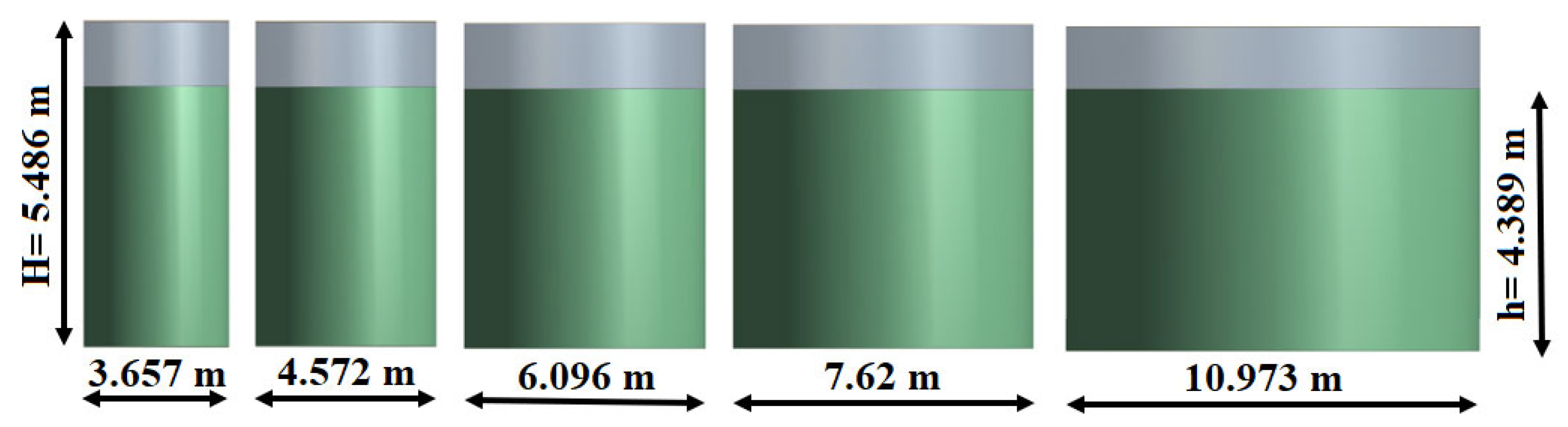
The typical cylindrical steel tanks of 15,000-, 23,000-, 42,000- and 63,000-, and 137,000-gallons capacity are considered for the structural analysis. Details are tabulated in
Table 1 and shown in
Figure 1.
The tanks are made up of structural steel with the following properties: density of 7850 Kg/m
3, Young’s Modulus of 210 GPa, poison ratio of 0.3, yield strength of 250 MPa, and ultimate strength of 450 MPa [
33]. They are ground-supported, and the contained fluid is water with a filled level of up to 80% by volume. Structure analysis is done using different displacement amplitudes and excited at resonance frequency to analyze the structural response and behavior of the tank. Critical loadings in terms of H/D ratio have been analyzed.
2.2. Code-Based Evaluation
Seismic design codes like the IITK-GSDMA guidelines for seismic design of liquid storage tanks [
34], Eurocode 8,part4 (related to tanks, silos, and pipelines) [
35], American Petroleum Institute API 650 [
32], and American Water Works Association AWWA D-100 [
36], which deals with ground supported circular steel tanks, etc. provide the standard procedures for the calculation of various parameters, e.g., hydrodynamic sloshing pressures, base shearing, and overturning moments; they also provide a seismic resistive design that withstands earthquakes safely.
These codes consider fluid contained in the tank as an equivalent mechanical model of a spring-mass system with two different masses oscillating with different frequencies, i.e., convective and impulsive, and they are situated at different tank heights. According to Eurocode 8 [
35], to calculate the hydrodynamic impulsive pressure at the tank wall due to liquid sloshing, the following equation is used, as shown below.
where
,
,
(.), and
(.) are modified Bessel functions of order 1 and its derivative, and
Ag(t) is the ground acceleration time history. The convective pressure component is represented and calculated using Equation (2) [
12].
where
,
J1 is the Bessel function of the first order,
equals 1.84, and
Acn(t) is the reactive acceleration of contained fluid developed as a result of
Ag (t) (ground acceleration time history) and called convective acceleration time history.
For the calculation of total hydrodynamic or sloshing pressure in the tank, both impulsive and convective parts are calculated using Equations (1) and (2) and combined using the Square Root of Summation of Squares (SRSS) rule. For the evaluation of both pressures along with the tank wall, substitute r = R (tank inner radius), θ = 0 or 180°, h = fill level, and y = value of interest along with the height of the tank wall. In this article, the tank models are base excited using displacement loadings; these displacement base excitations are transformed to equivalent ground acceleration time history, Ag(t), and the convective acceleration is evaluated using the response of the SDOF oscillator with a convective frequency and an appropriate damping ratio for the sloshing of the fluid. These equations subsequently provide the basis for validating the finite element modeling procedure.
2.3. Modeling Procedure
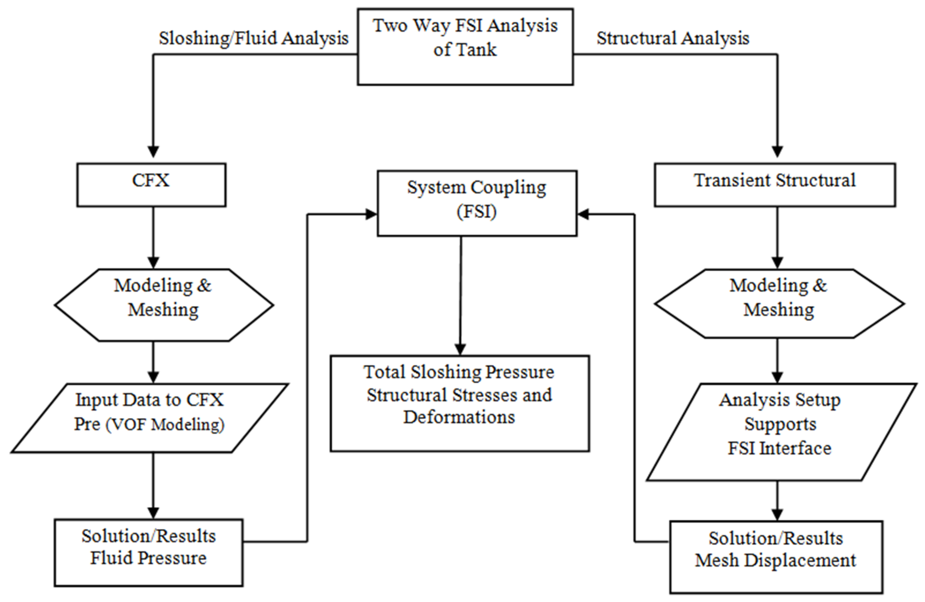
For modeling and analysis of cylindrical steel tanks, FE modeling software, ANSYS Workbench, is used. This numerical investigation has been performed using two analysis systems of ANSYS, namely:
Modal analysis is performed for the numerical estimation of fluid fundamental frequencies (natural), called the convective frequencies, and mode shapes and to analyze the variations of the convective frequency with the H/D ratio of tank models.
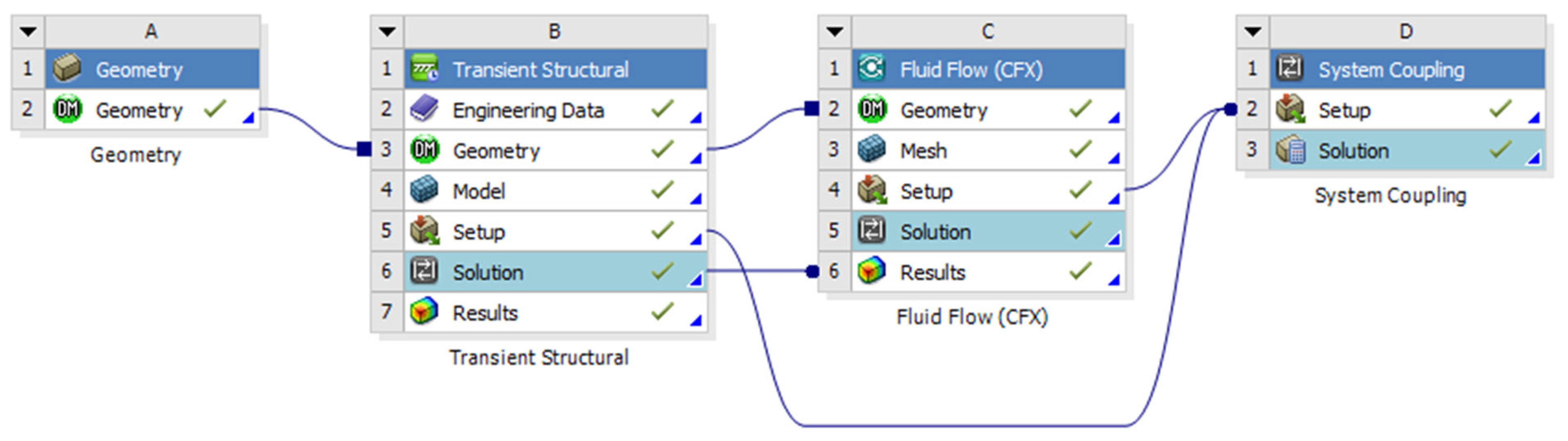
Whereas FSI analysis is used to evaluate the effects of seismic sloshing on the tank structure, this analysis system comprises fluid and structural parts as the fluid storage tank has two domains, i.e., contained fluid and tank structure. Upon seismic excitations, the fluid moves relative to the tank structure and interacts with the tank’s inner structure, resulting in a complex vibrational behavior of the tank structure. The fluid analysis has been done in ANSYS and structural analysis in the transient structural module of ANSYS Workbench. Both the solvers (CFX and Transient Structural) are coupled with ANSYS system coupling capability and transfer data both ways; the CFX solver estimates the fluid hydrodynamic pressure due to seismic sloshing, whereas the transient structural solver evaluates the structural response (mesh displacement) in response to imported CFX sloshing pressure. The flow chart of the two-way FSI analysis is shown in
Figure 2. The coupled FSI analysis setup is shown in
Figure 3.
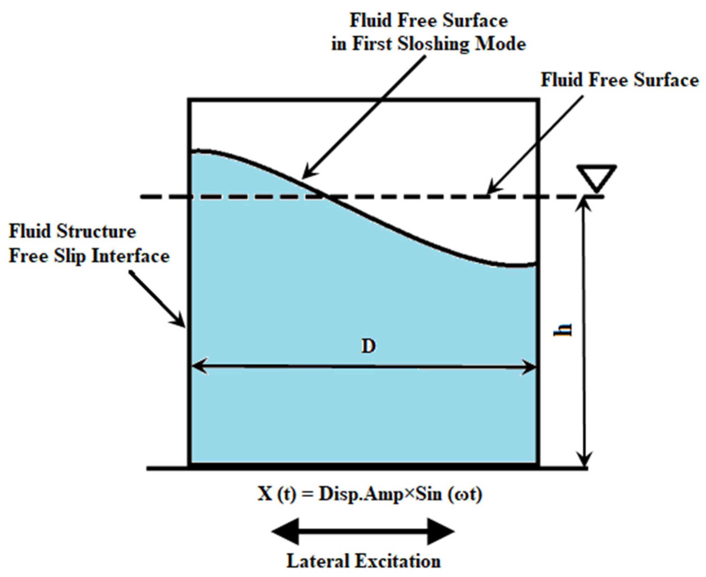
To represent the seismic activity harmonic displacement, excitation is applied to the tank base, which is represented mathematically as X(t) = D Sin
t; D is the displacement amplitude of lateral loading, and
is the excitation frequency. The schematic view of the tank, along with the assigned load and tank fluid boundary condition, is shown below in
Figure 4. For this analysis, the excitation frequency considered is the first convective frequency of the respective tank model. Modeling of both fluid and tank structures is done using solid and shell elements, respectively, with structured brick meshing. To ensure 100% node mapping between fluid and tank structure, structured hexahedral meshing is generated using the slicing technique [
37].
2.4. Modal Analysis
The dynamic analysis of cylindrical steel tank models starts with the modal analysis, whose aim is to calculate the natural frequencies and mode shapes of the fluid contained in the tank. The frequency response has been evaluated using the FEM software ANSYS. Water is considered a fluid and modeled as a solid body using Fluid30 elements. Fluid30 is an 8-noded hexahedral fluid element suitable for modeling 3D contained fluid. After numerical estimation of the convective frequencies of each tank model, they are compared with the design code (Eurocode8). Theoretically, the convective frequency is calculated using Equation (3) [
38].
where
is the convective frequency in rad/sec,
g is the gravitational acceleration,
R is the tank inner radius,
h is the fluid depth, and
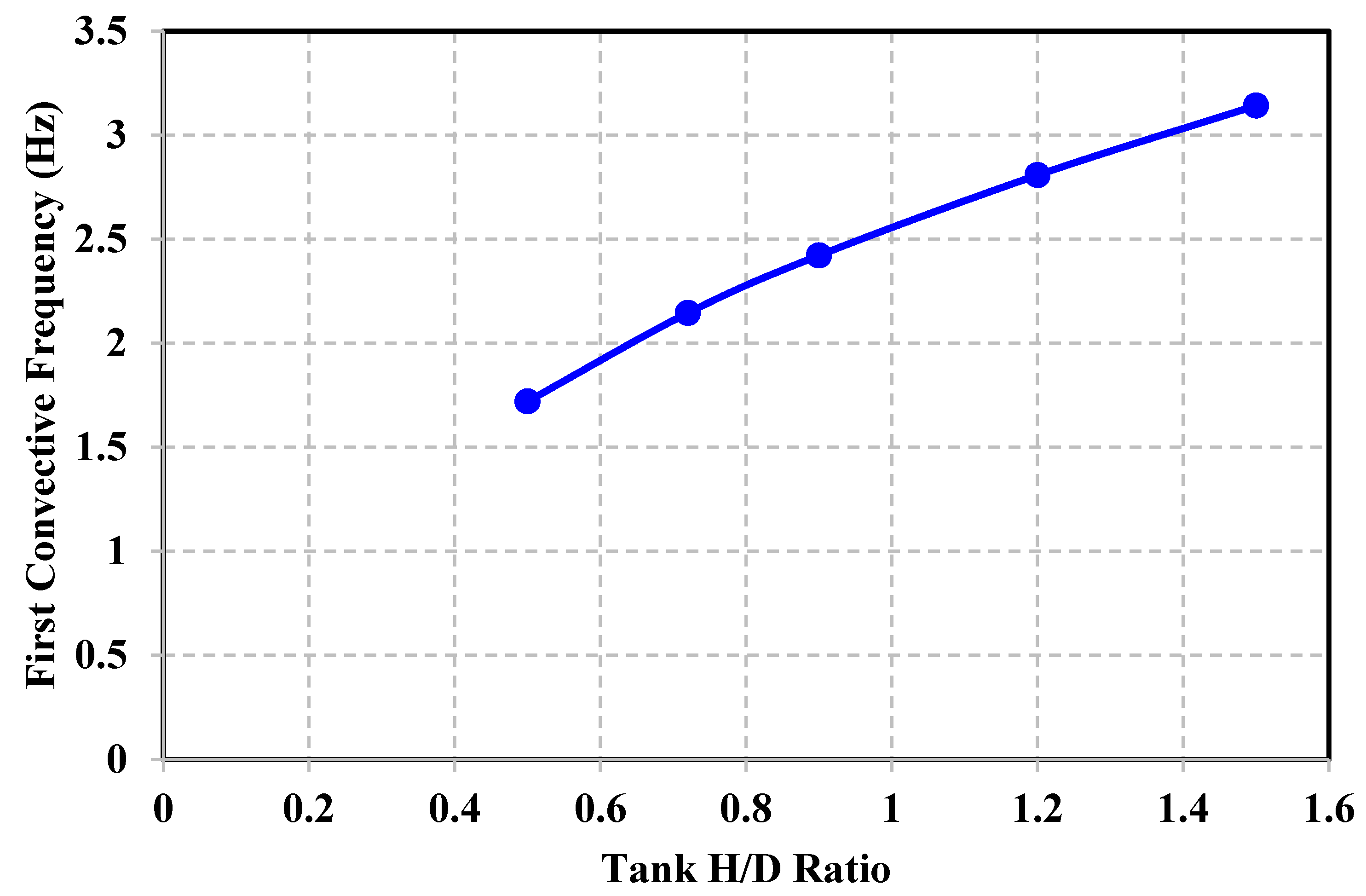
are the zeroes of the first derivative of the Bessel function of the first kind and first order. The first convective frequency of five tank geometries is evaluated from ANSYS and theoretically using Equation (3), as shown in
Table 2; comparison shows no difference between ANSYS and design code convective frequency values, which ensures the reliability of ANSYS results. It is indicated that as the diameter of the tank decreases, the convective frequency increases asymptotically, as shown in
Figure 5.
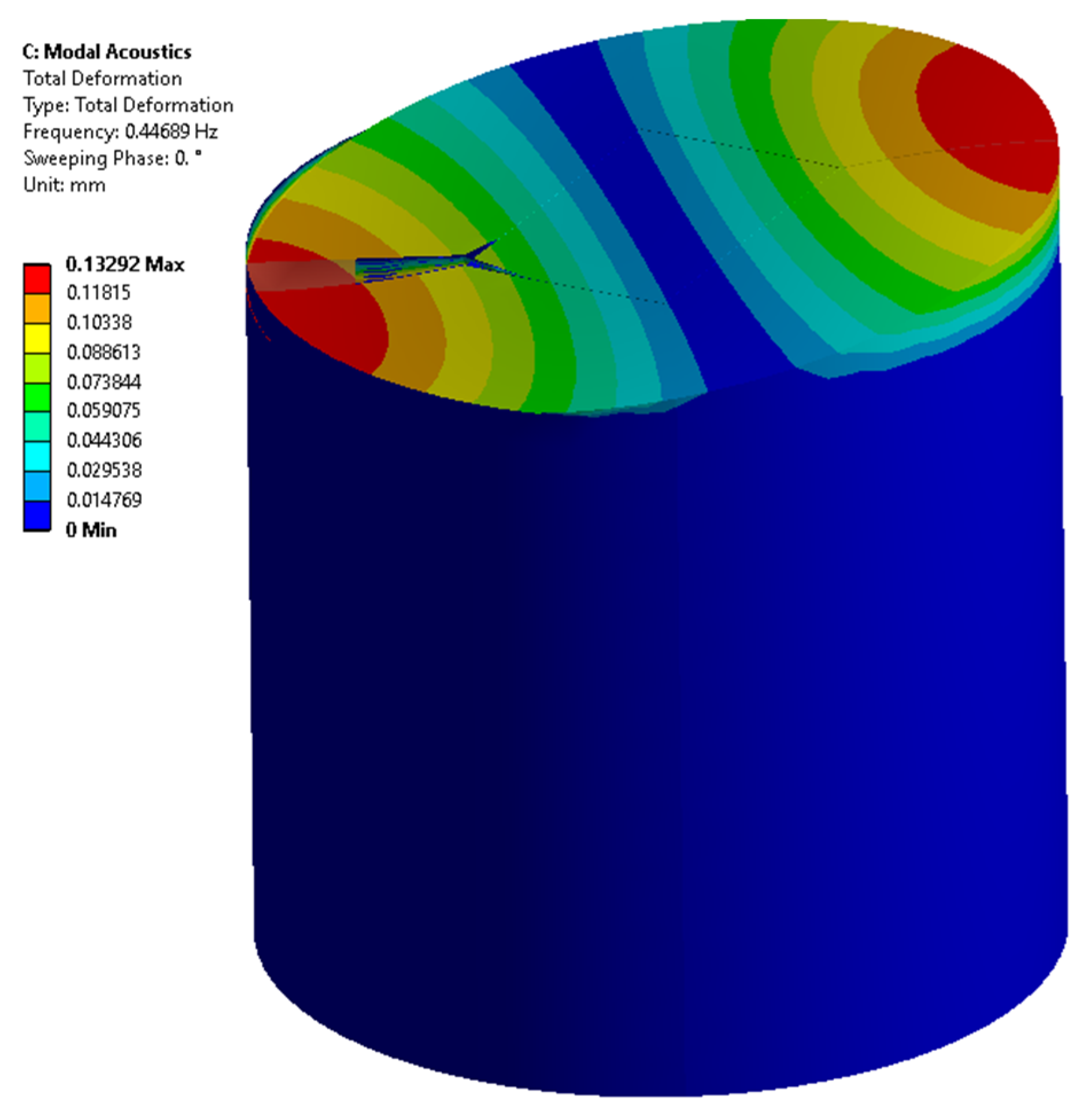
It is observed that the convective frequency of a tank with a diameter less than the tank height, i.e., D < H (slender tank), is higher than the tanks with D > H (broad tank). The present study uses only the first convective frequency as the excitation frequency and the corresponding mode shape, as shown in
Figure 6.
2.5. Validation of FE Model
The reliability and validation of the CFD model are required to ensure the accuracy of the modeling procedure. Both grid or element and time step sizes are selected based on several sensitivity analyses. Sensitivity studies are performed based on three criteria: First, CFD solution variations should be less when analyzed in terms of mesh and timestep size, which means consistent solutions. Second, the solution imbalances should be less than 1%.Third, the residual values should be converged at every timestep. After fulfilling both convergence and consistency of numerical results, i.e., pressure variations at the tank wall bottom and convective and impulsive heights in response to seismic excitations, they must be compared with some design code.
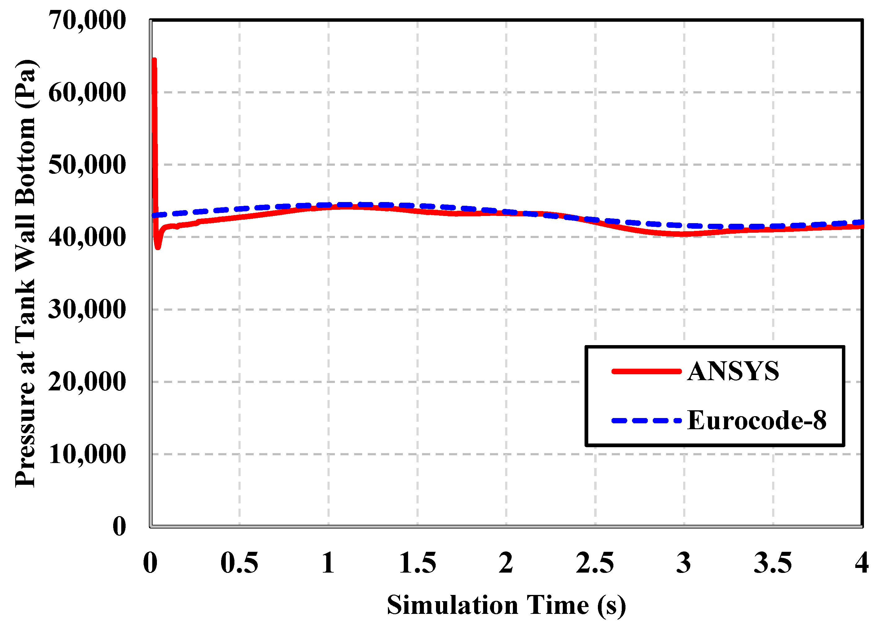
For validation of numerical methodology and modeling, analyses have been performed on a slender tank having a H/D ratio of 1.2 with harmonic base excitations of 5 cm and a 40 cm amplitude excited at 0.5ω
cn. Sloshing pressures at convective height, impulsive height, and tank wall bottom have been evaluated in ANSYS CFX and compared with the design code (Eurocode8). The convective and impulsive heights are calculated using expressions given in Eurocode8 [
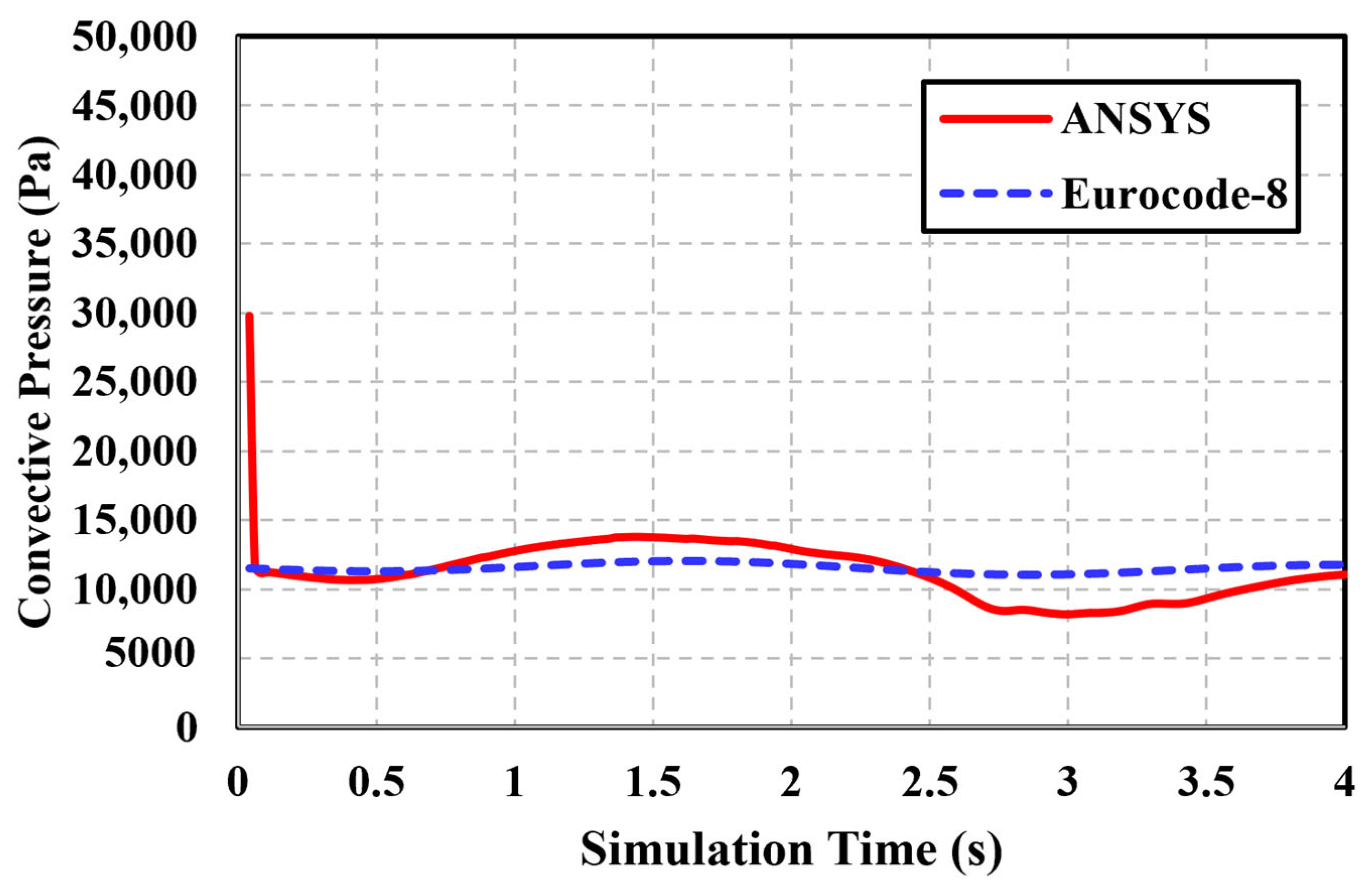
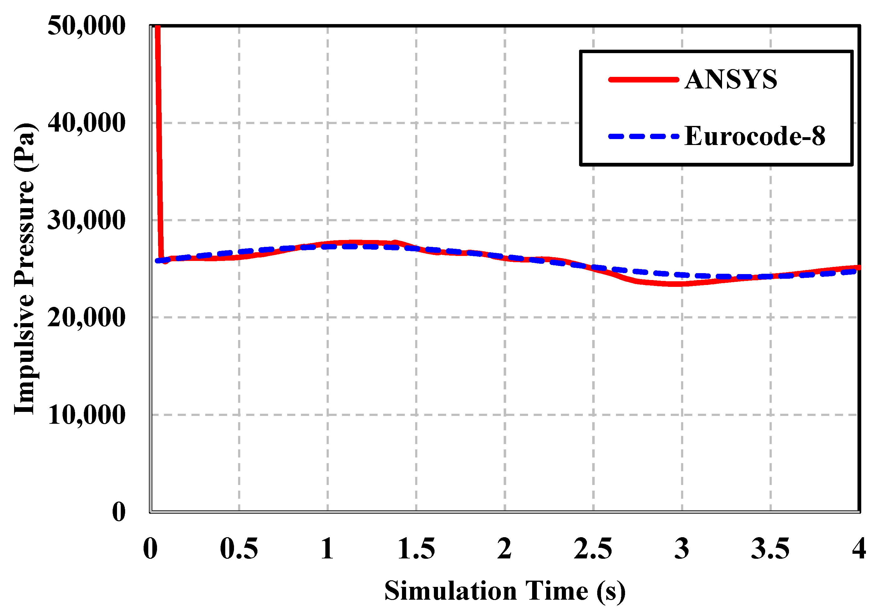
35], whereas impulsive, convective, and total sloshing pressures are evaluated using Equations (1) and (2) at respective heights. The percentage errors for displacement amplitudes of 5 cm at convective, impulsive, and tank wall bottom are 2.4%, 2.25%, and 1.25%, respectively. Similarly, the comparison of pressure curves for 40 cm displacement amplitude in ANSYS and design code (Eurocode8) indicates very good agreement of results as shown in
Figure 7,
Figure 8 and
Figure 9, as the percentage errors of convective, impulsive, and total sloshing pressures are 8.4%, 2.7%, and 2.2%, respectively.
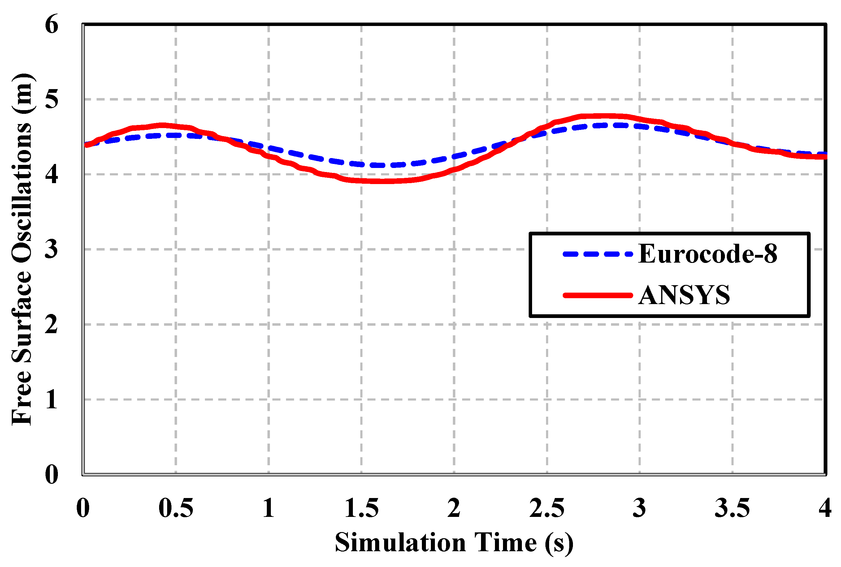
To ensure the appropriate selection of turbulence model for capturing process turbulence and seismic sloshing, the oscillations of the free surface have also been tracked in CFD post and compared with the oscillation evaluated using design code. The comparison of free-surface oscillations has been shown graphically in
Figure 10 and has a percentage error of 4%, which validates the selection of the turbulence model.
There is no significant difference between ANSYS- and Design-Code-(Eurocode8) based pressures, which indicates the reliability and accuracy of ANSYS CFX; therefore, the modeling procedure is validated.
To verify the FE model, the hydrodynamic hoop and shear stress resulting from the variation of sloshing pressure at 40 cm amplitude have been evaluated using appropriate shell theory. The maximum values of circumferential and shearing stresses in the tank walls are required for the evaluation of tank structural response under seismic loadings. The design procedure adopted by Veletsos and Yang [
39] was also reported in ASCE-1984 [
40], and a similar step-by-step procedure for the seismic design of circular liquid-containing structures [
41] is used to determine the maximum values of stresses. These values of maximum hoop or circumferential and shear stresses are then compared with the transient structural stress values, showing error percentages of 2.4% and 5%, respectively, as shown in
Table 3. This shows the accuracy of FE modeling as well.
2.6. Fluid-Structure Interaction Approach
The fluid-structure interaction approach is a multifaceted physics approach commonly occurring in systems where fluid interacts with the structure, which may result in structural deformations. The fluid may be flowing or contained; in our case, the water is contained in the tank’s solid structure. When the flexible tank structure is excited seismically, the fluid in the tank oscillates and exerts pressure on the inner tank wall surfaces, also called the fluid-structure interface [
42].
This article uses a bi-directional FSI approach, in which the CFX code and mechanical application solver execute the simultaneous simulation using coupled iterations. During this, each field solver gathers the required data from the other solver for the estimation of numerical results.
2.7. Fluid Domain Analysis
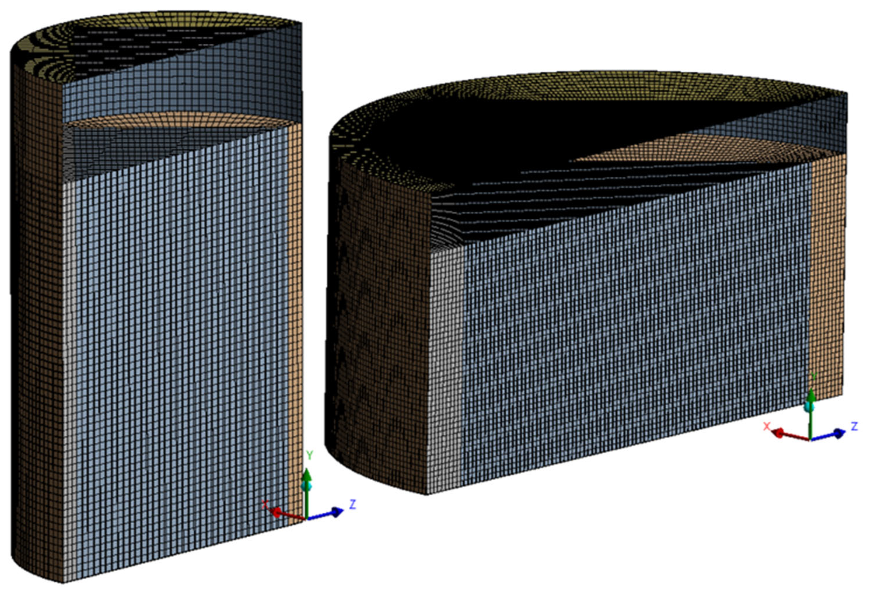
Fluid domain analysis is performed using ANSYS CFX, which iteratively solves the seismic problem and computes the hydrodynamic pressure variations. The fluid is assumed to be incompressible, inviscid, and irrotational, with a mass density of 998 kg/m
3. There is no heat transfer in the fluid model, and air above the fluid-free surface has a pressure of 1 atm. It is a multiphase (air and water) free-surface fluid flow problem; therefore, the volume of fluid (VOF) model is used, which is most suitable for sloshing analysis [
43]. The fluid part is modeled as a solid element with a fine and uniformly structured hexahedral mesh, as shown in
Figure 11.
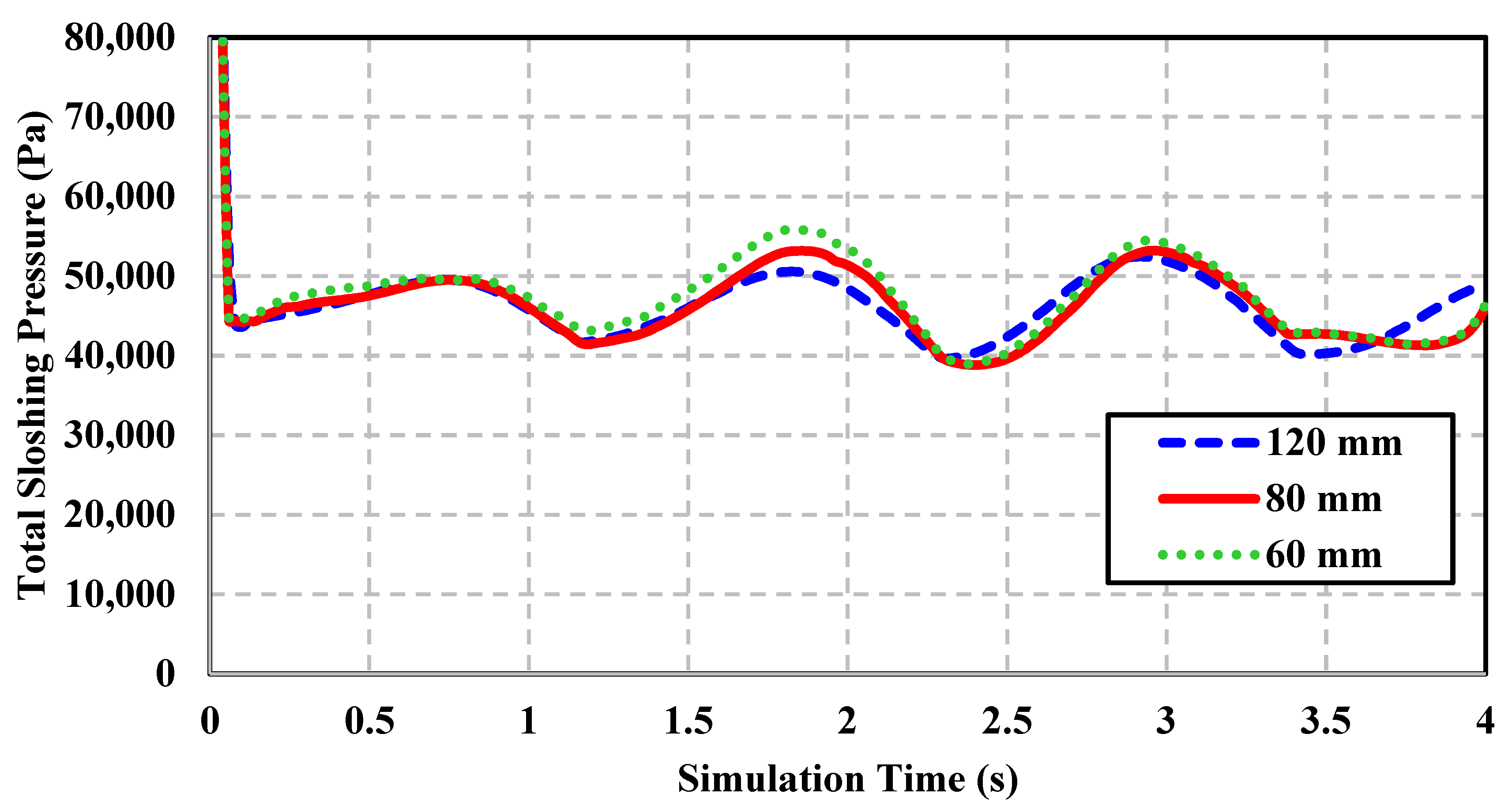
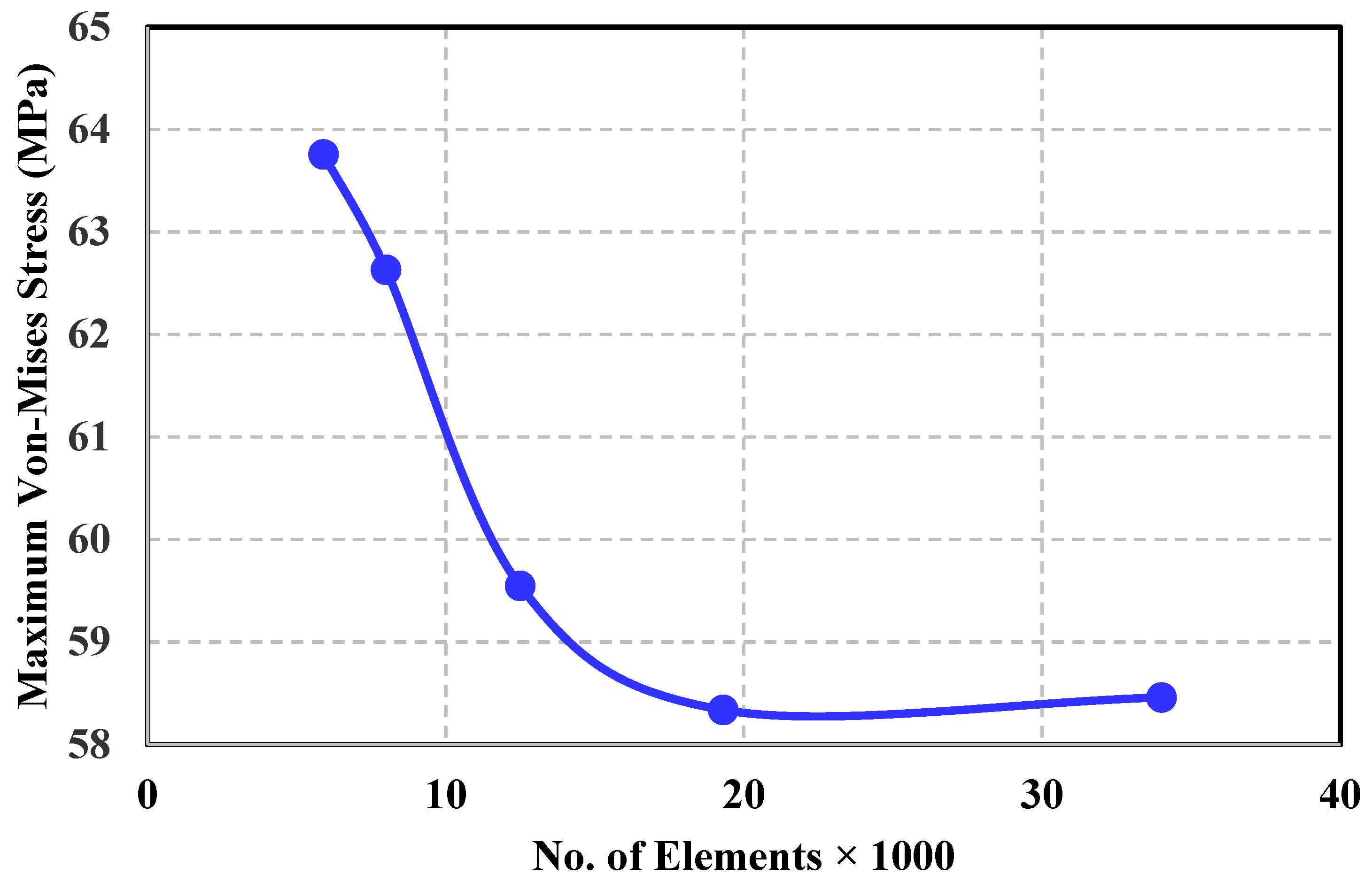
The slicing technique is used to generate a uniform brick mesh using HEX 8 elements to ensure perfect node mapping of pressure from the fluid part to the tank structure. The element size has been selected based on sensitivity analysis (mesh independence study); in this regard, the following grid sizes are tested: 120 mm, 80 mm, and 60 mm. Among them, 80 mm is selected for tank geometries. The result of the sensitivity analysis of the tank model with a H/D ratio of 1.2 is shown in
Figure 12. It is observed that for the selected grid size, the variations of total sloshing pressure (summation of convective and impulsive pressure) are less than 5%. Similarly, asuitable time step size has also been selected so that the iterative solution may converge and there can be consistent CFX results.
The seismic load is applied to the tank base in terms of displacement time history for 4 s. In the author’s previous research, it was found that the flat-top cylindrical steel tank with an H/D ratio of 1.2 exhibits the yielding phenomenon within 2 s of analysis [
28], and by performing tank roof shape or design modifications, it became safe. The tank was acted upon by resonant seismic excitations for 4 s, having four loading peaks (peak ground acceleration, PGA) of 0.3 g. The present study investigates the effects of variation in the H/D ratio on the structural response when excited at convective resonance using the same duration.
To capture process turbulence, the RNG K-є model is used. It is a two-equation turbulence model, and it provides adequate computational accuracy to capture sloshing turbulence. Since the fluid is considered inviscid, no mesh refinement is required near tank walls, and a free-slip boundary condition is implied for the tank walls. Different harmonic excitation amplitudes have been examined, ranging from 5 cm to 50 cm (with an interval of 5 cm). The displacement loading is implied as a displacement diffusion mesh motion model. In this model, the displacement of nodes at the interface boundary, i.e., the fluid boundary, is obtained as solution data from the structural solver, whereas the motion of all remaining nodes is determined by the displacement diffusion model. Both the fluid and structural solvers are coupled together using ANSYS system coupling, which uses fully implicit discretization of the equations at any given time step. The solution methodologies used in two-way FSI analysis are presented in
Table 4.
When the tank is excited or displaced, the water inside displaces relative to the tank wall and exhibits a sloshing phenomenon in which a water-free surface moves in response to applied seismic excitations and exerts hydrodynamic forces to the tank wall and roof.
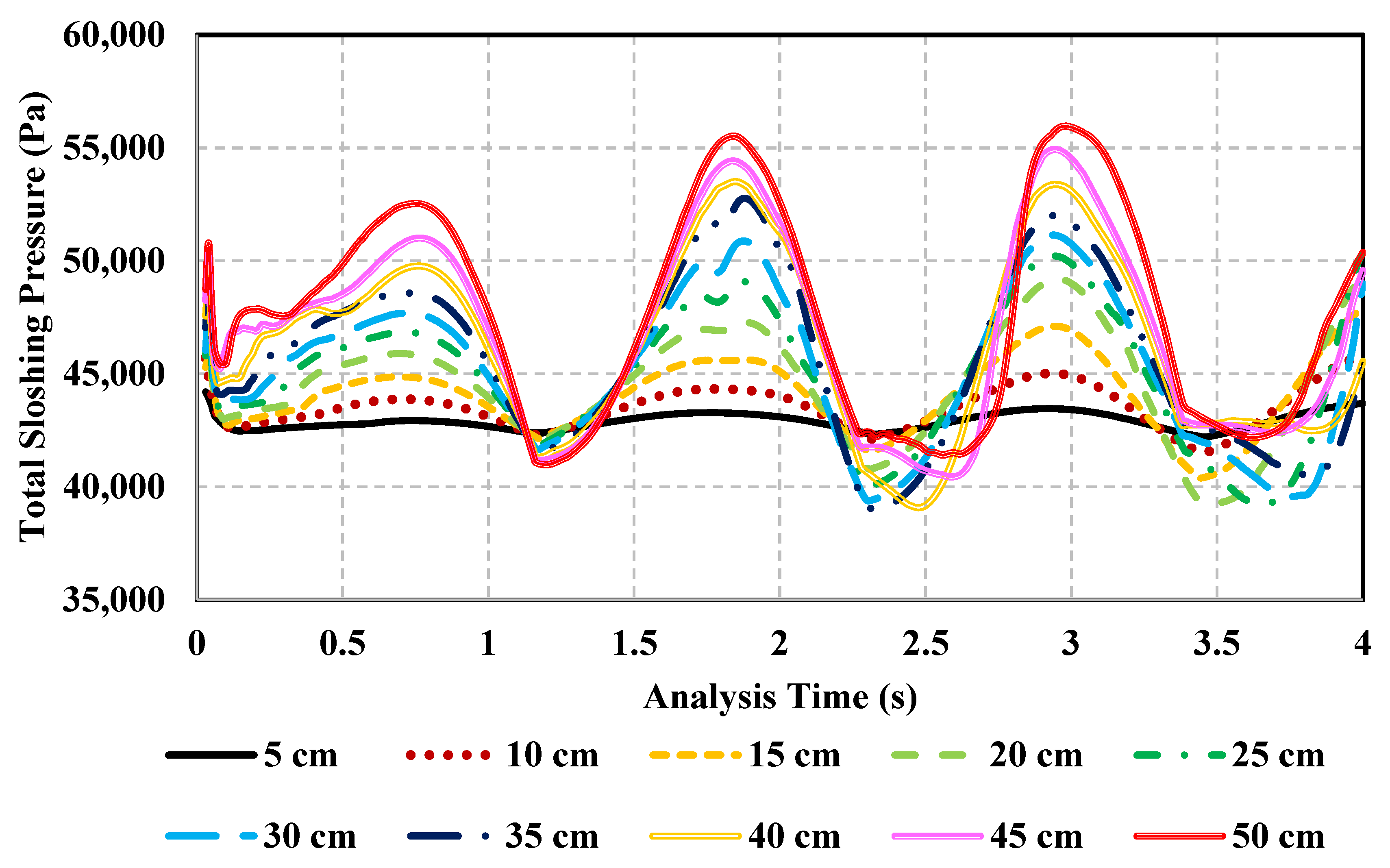
It is observed that for any particular excitation amplitude, the amplitude of sloshing pressure increases with respect to time; similarly, the pressure amplitude also increases with the increase in excitation amplitude, as shown in
Figure 13, which indicates the comparison of pressure amplitude from the 5 to 50 cm displacement amplitude for the H/D ratio of 1.2. The sloshing or hydrodynamic pressure increases with excitation amplitude, resulting in the impact of water on the tank wall and roof. Hydrodynamic pressure variations, also called maximum sloshing pressure, resulting from seismic sloshing and structural displacement against each excitation amplitude are then imported to the structural module via the ANSYS system coupling module for analyzing the response of five tank structures against each loading case.
2.8. Structural Analysis
The structural behavior of ground-supported cylindrical steel tanks with varying H/D ratios subjected to seismic excitations at convective resonance has been evaluated using Transient Structural. For the structural part, the transient analysis solves the equation of motion:
where
M,
C, and
K represent the system mass, damping, and stiffness matrices,
Ag(t) represents the ground acceleration time history, p is the hydrodynamic pressure, D is the direction of ground excitations, and
x(t) is the displacement vector. The H/D ratio of storage tanks classifies them as slender and broad tanks. Tanks with an H/D ratio of 1 and greater are slender, whereas tanks with an H/D ratio less than 1 are considered broad. In our research, five tank geometries are considered, in which the tank diameter varies and its height remains fixed. This article accounts for the effect of variations in tank diameter on the seismic response of tank structures subjected to various displacement loadings. These displacement loadings may represent the different peak ground values in terms of displacement, velocity, or acceleration. Based on various analyses performed on tanks with H/D ratios of 1.5, 1.2, 0.9, 0.72, and 0.5, critical loads have been evaluated against each H/D ratio of the tank structure. At various displacement amplitudes, the structural response has been studied to analyze their behavior under resonant excitations.
The steel tanks are modeled using SHELL 181 elements with four nodes with six degrees of freedom at each node [
41] and meshed using brick meshing. The number of elements is selected based on a structural mesh independence study. The mesh independence of the tank with an H/D ratio of 1.2 at a displacement amplitude of 5 cm is shown in
Figure 14. The main advantage of hexahedral or brick meshing is providing a good mesh quality of more than 0.89 for all of the considered tank geometries and providing perfect node mapping so that the total pressure resulting from sloshing has been transferred with 100% node mapping from CFX to the tank inner wall surface called the FSI interface in the transient structural module.
3. Results and Discussion
Various simulations have been performed at different peak ground displacements (PGD), with displacement amplitudes ranging from 5 to 50 cm, and applied as lateral harmonic excitations at the first convective resonance. The same displacement amplitude range has been considered for five tank geometries, but they are excited at the tank’s convective frequency (ω
cn), which is different for each tank (ω
cn increases with a decrease in tank diameter; see
Figure 3).
Equivalent peak ground acceleration (PGA) decreases with the H/D ratio. The tank with an H/D ratio of 1.5 has a displacement loading that represents a seismic peak ground acceleration range of 0.05 g to 0.5 g (with an interval of 0.05 g). For the tank with an H/D ratio of 0.5, an equivalent PGA range is 0.015 g to 0.15 g (with an interval of 0.015 g). The parameters of the used seismic excitations, along with equivalent PGAs for each tank model, are shown in
Table 5. These values are considered the PGA of a particular earthquake event at resonance for 4 s. When the liquid tanks are subjected to dynamic loadings, the fluid exhibits a sloshing phenomenon that results in hydrodynamic pressure on the tank structure. Due to fluid structural interaction, the tank undergoes complex vibrational behavior; therefore, to study this complex response, the tank fluid system is simplified to a two-mass model that, according to Housner [
4], is represented as an equivalent mechanical model called the spring-mass model.
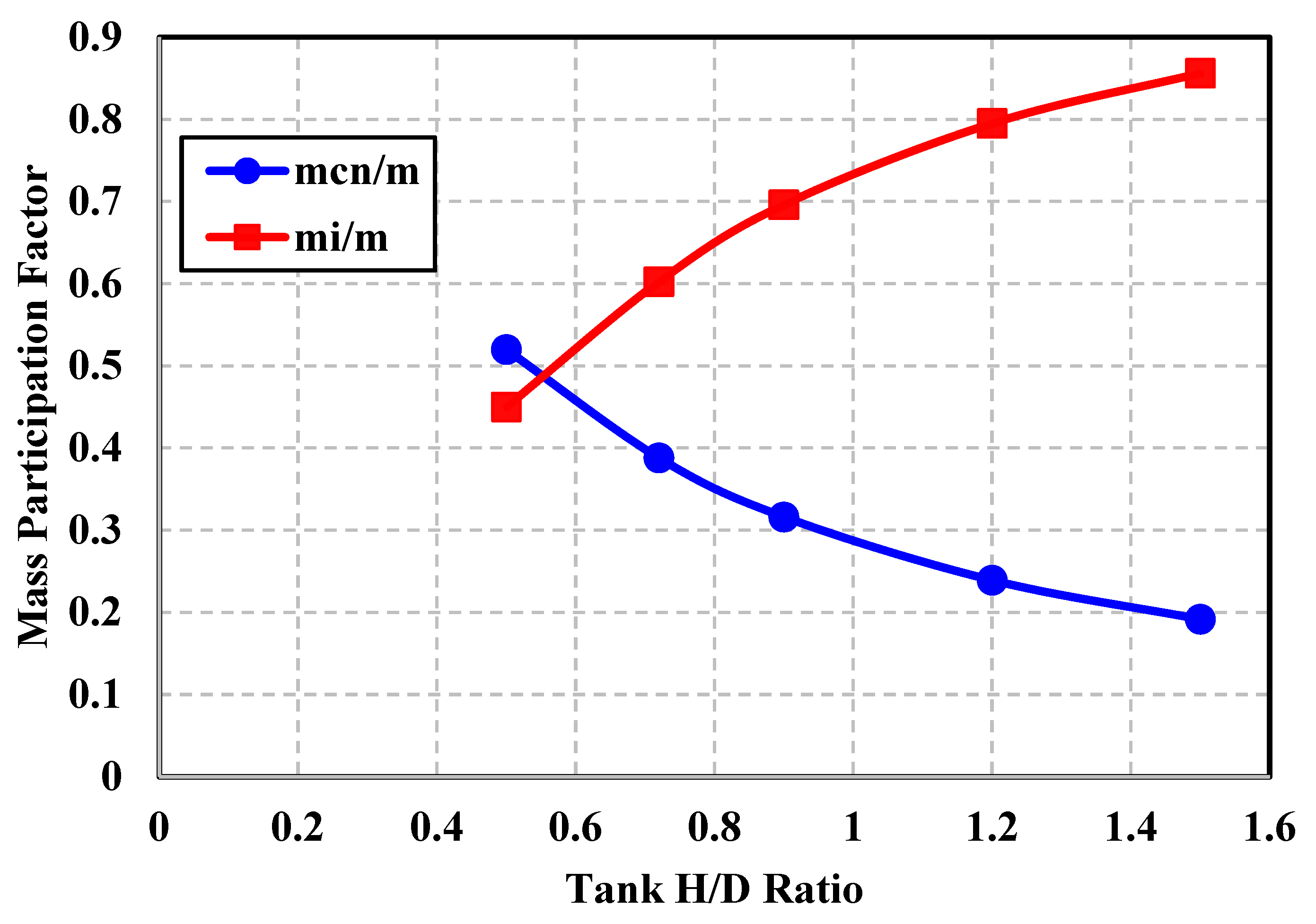
These two masses are named impulsive and convective mass.Their ratios to the total mass of contained fluid are called mass participation factors. It is observed that as the tank diameter decreases, the impulsive mass participation increases asymptotically; for an H/D ratio of 1.5, more than 85% of water participates as impulsive mass compared to a tank with an H/D ratio of 0.5 having 45% of impulsive participation. The convective mass participation factor decreases with increase in tank diameter. The variations of mass participation factors with tank H/D ratio are shown in
Figure 15.
The variation of the tank H/D ratio affects the seismic structural response through the changing convective frequency and mass participation factors. Five tank models with H/D ratios of 1.5, 1.2, 0.9, 0.72, and 0.5 are examined to study the dynamic behavior under various seismic loadings for the evaluation of critical loadings. The tanks with H/D ratios of 1.5 and 1.2 are considered slender tanks, as their tank diameters are less than the tank height. An H/D ratio of 0.9 is considered medium, and 0.72 and 0.5 are considered broad tanks due to large tank diameters. The Von-Mises stress for an H/D ratio of 1.5 varies linearly with the displacement amplitude and remains safe up to a 30 cm displacement amplitude; beyond that, it exhibits yielding, as shown in
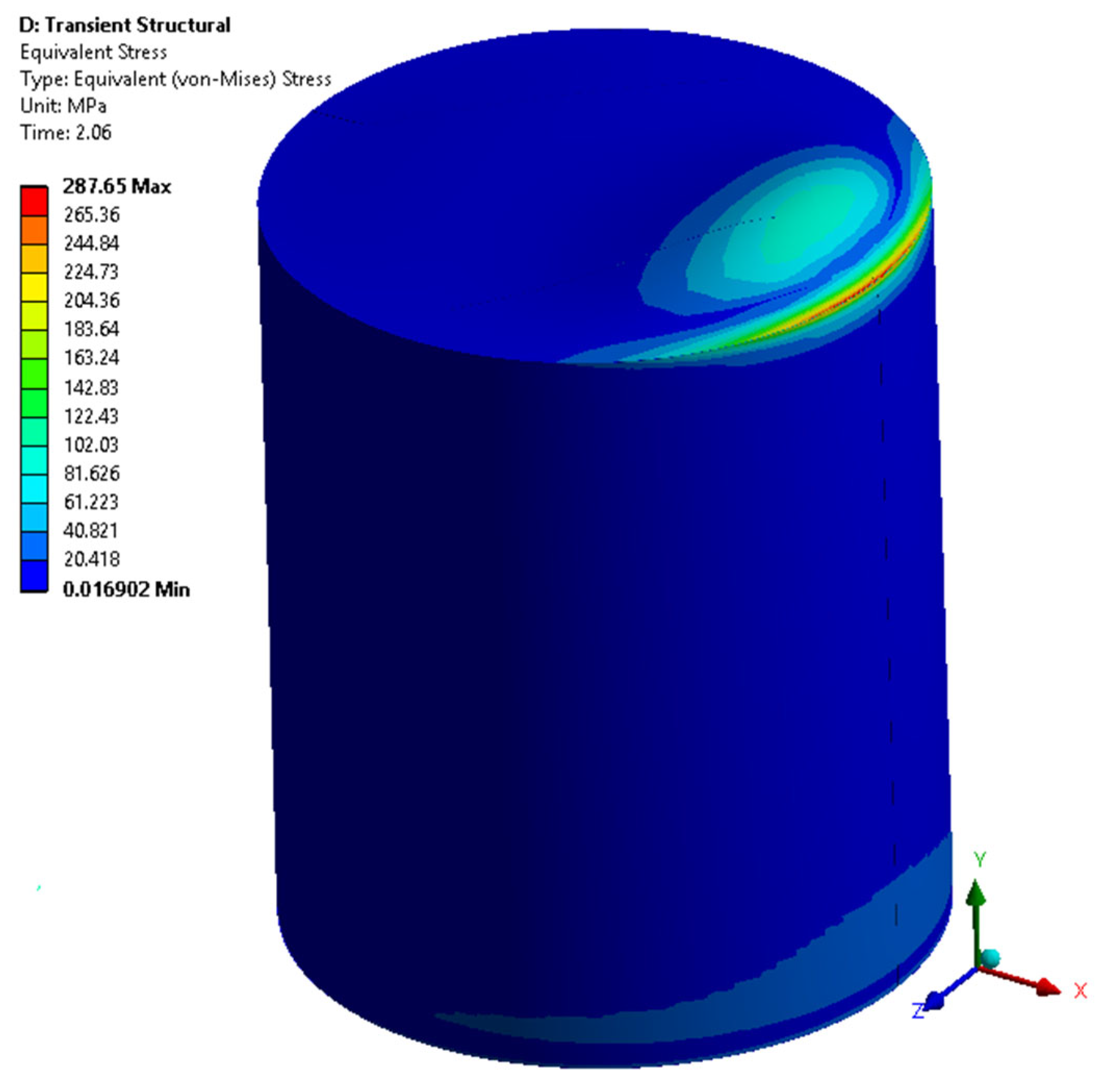
Figure 16. For a tank with an H/D ratio of 1.2, it is found that the tank remains structurally safe up to a 15 cm displacement amplitude with a maximum stress of 97 MPa. Then it increases exponentially, resulting in the tank yielding at a 20 cm amplitude.
Between 20 cm and 40 cm, the tank exhibits the yielding phenomenon, which starts at 20 cm, as shown in
Figure 17. There is full yielding at 40 cm, and from 40 cm onwards, the stress value increases exponentially to 407 MPa. For an H/D ratio of 0.9, the tank remains safe up to a 25 cm amplitude with a stress of 230 MPa. In terms of ground displacement amplitude, the safety limit of this tank geometry is high due to a slightly lower convective frequency compared to the convective frequency of an H/D ratio of 1.2, as shown in
Figure 5.
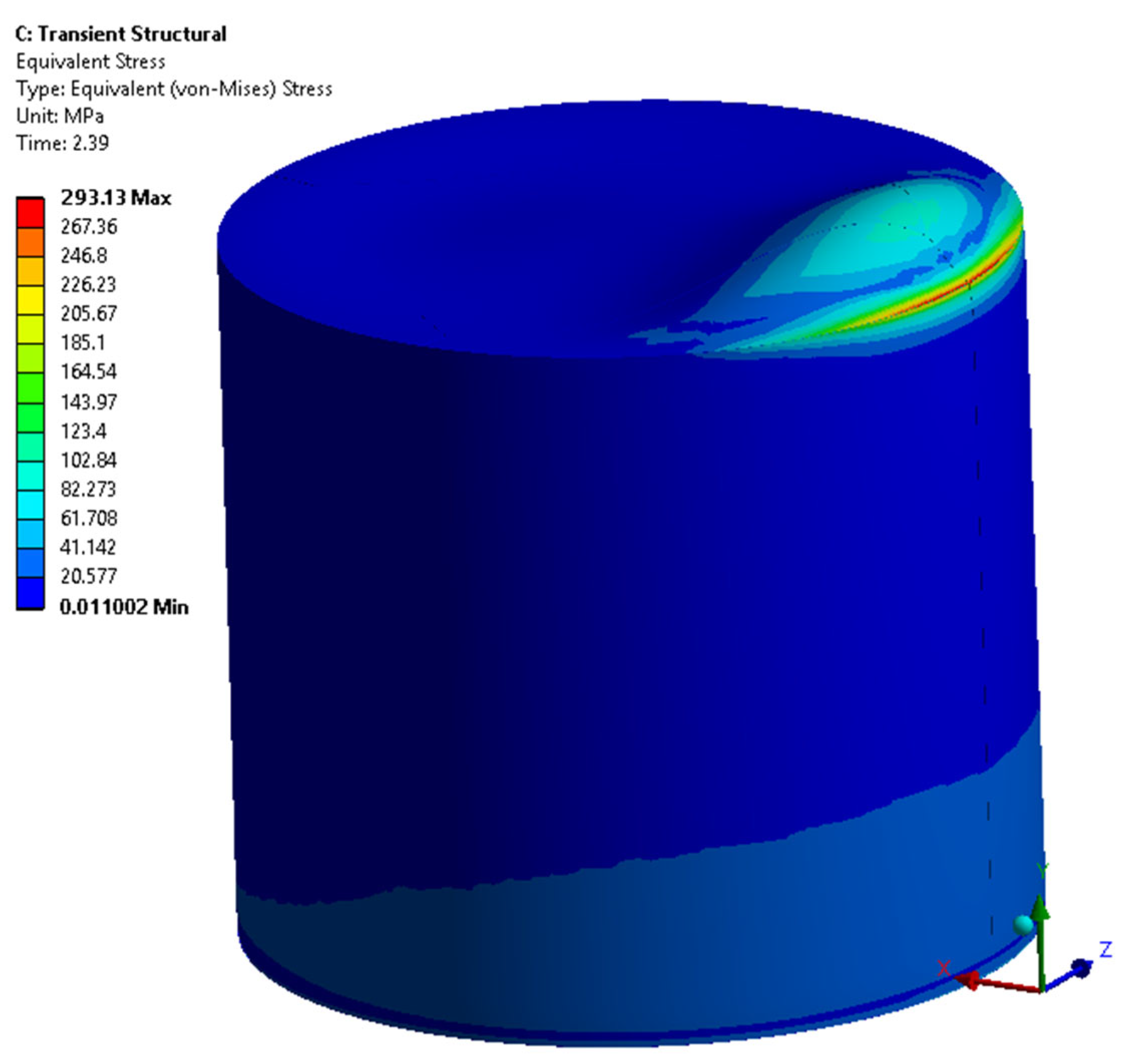
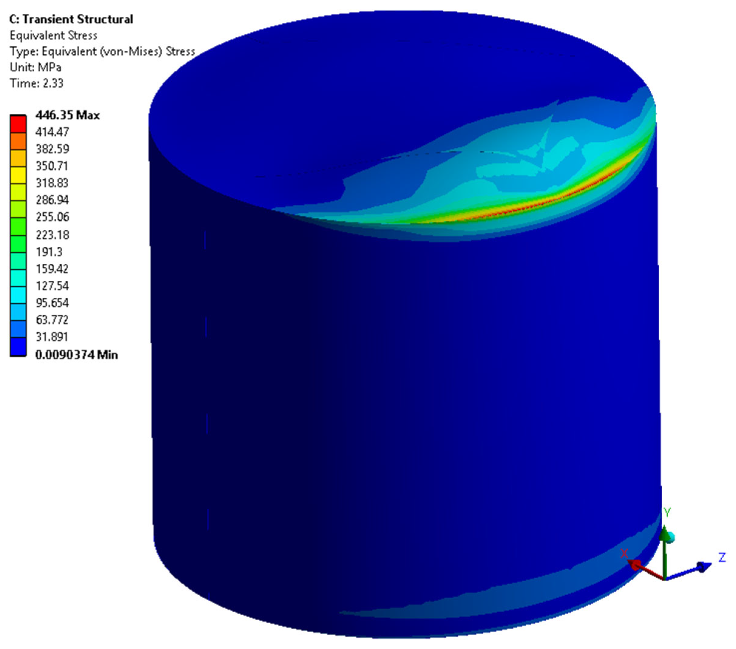
From 25 cm and on, stress increases asymptotically to the tank’s ultimate stress value. It exhibits yielding at 30 cm, as shown in
Figure 18, and completely fails to resist the seismic displacement at 40 cm and onwards, as shown in
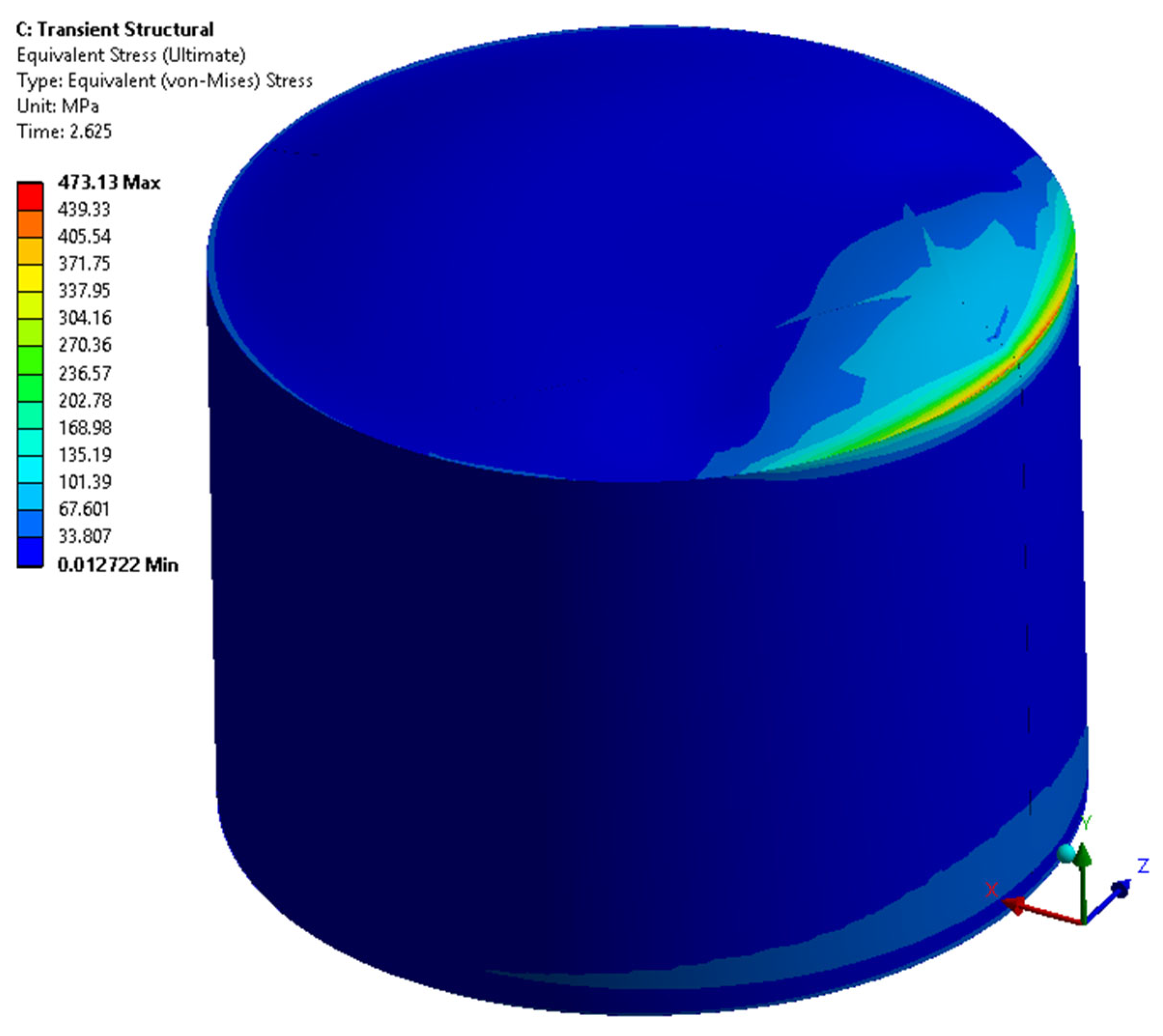
Figure 19. For the H/D ratio of 0.72, the tank remains safe up to 25 cm, with a maximum stress of 202 MPa.It then increases asymptotically to the point of tank failure at 35 cm and onwards, as shown in
Figure 20.
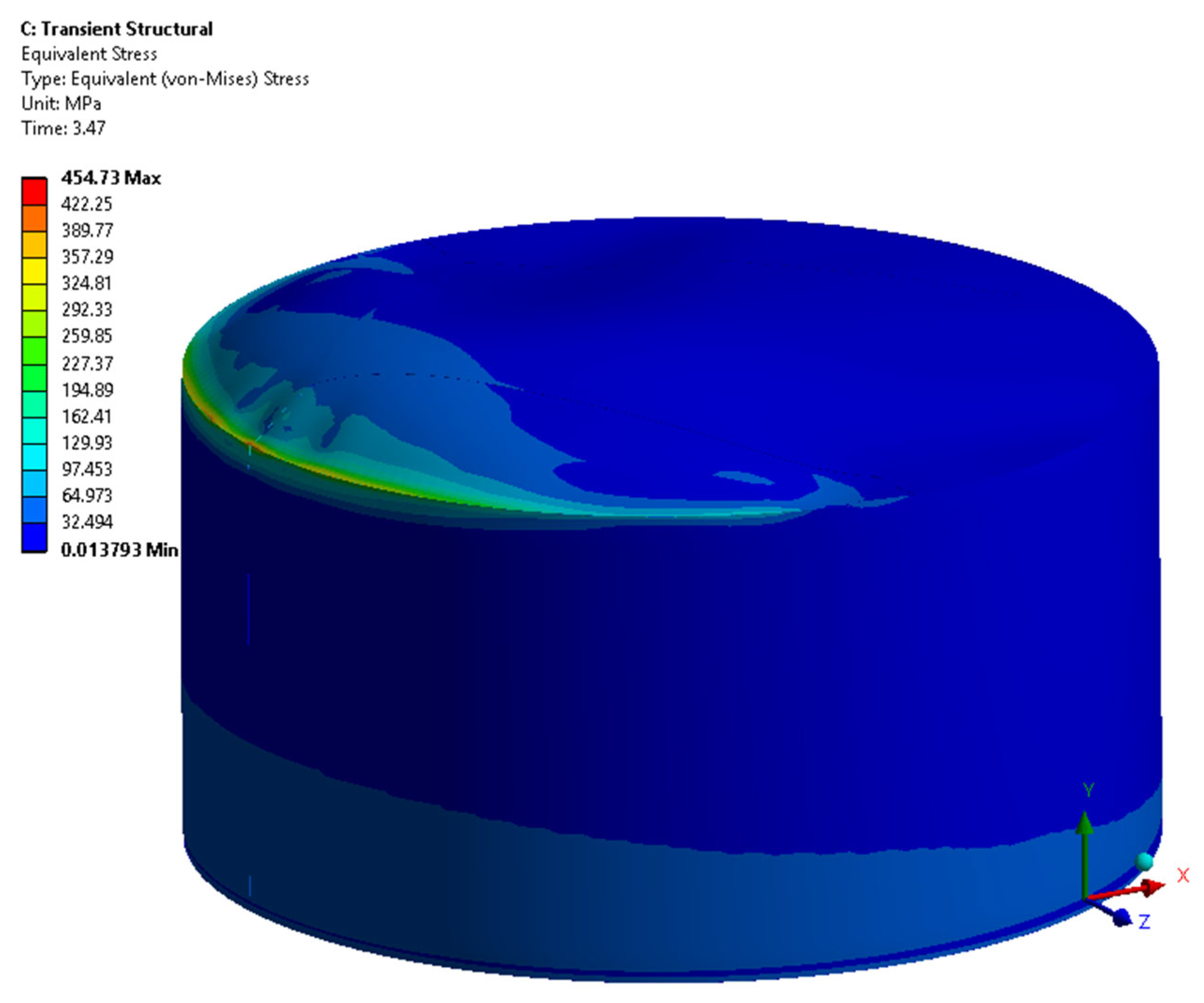
In the case of a broad tank (H/D of 0.5), the maximum stress increases exponentially with the displacement loadings and fails by crossing the tank’s ultimate strength (450 MPa) at a 30 cm displacement amplitude, as shown in
Figure 21.
The comparison of the structural behavior of five tank models is shown graphically in
Figure 22,
Figure 23 and
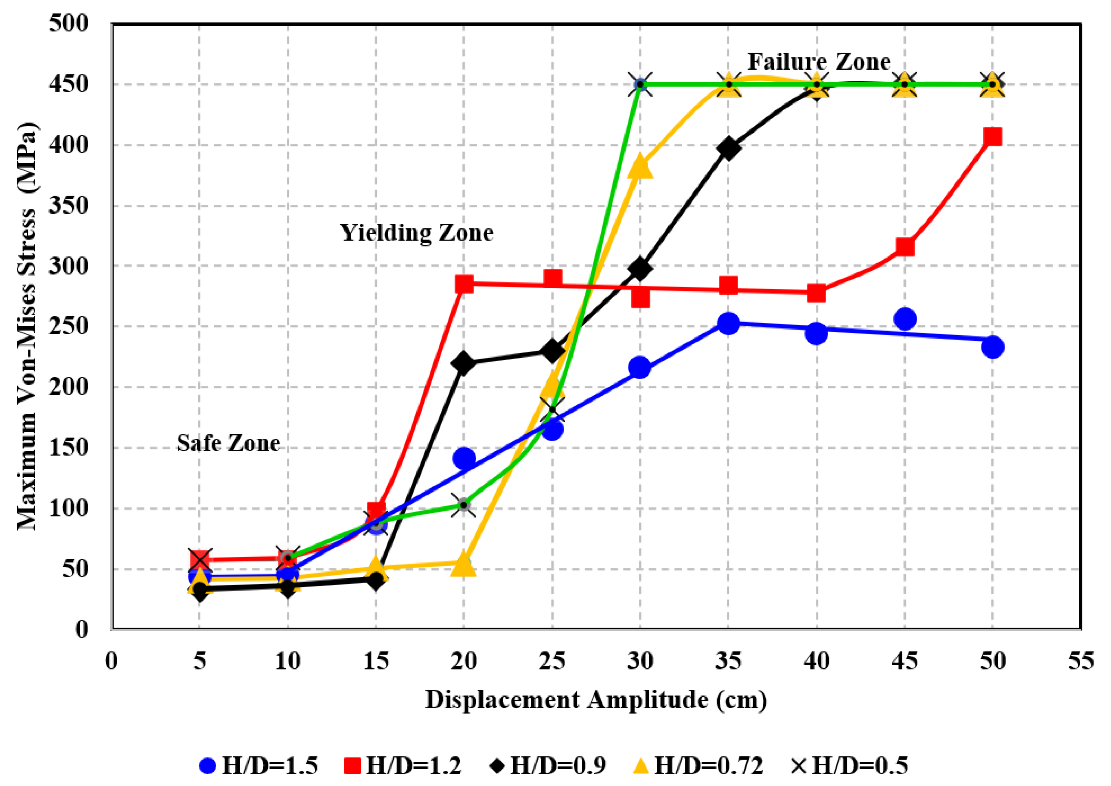
Figure 24. It is observed from the tank’s seismic response that it undergoes three transitional zones named safe, yielding, and failure zones, and they are categorized based on loading amplitudes and tank structural stress; the safe zone is below 250 MPa, the yielding zone falls between 250 and 450 MPa, and the failure zone is beyond 450 MPa. The safe zone is further classified into stable and unstable regions. The region where the tank structural stress does not change with the change in loading amplitudes (i.e., tanks with H/D ratios of 1.5, 1.2, and 0.5 are stable up to 10 cm, whereas 0.9 and 0.72 are stable up to 15 cm and 20 cm, respectively) is shown in
Figure 24. The unstable region lies beyond 10, 15, and 20 cm, respectively, as it exhibits a remarkable increase in stresses.
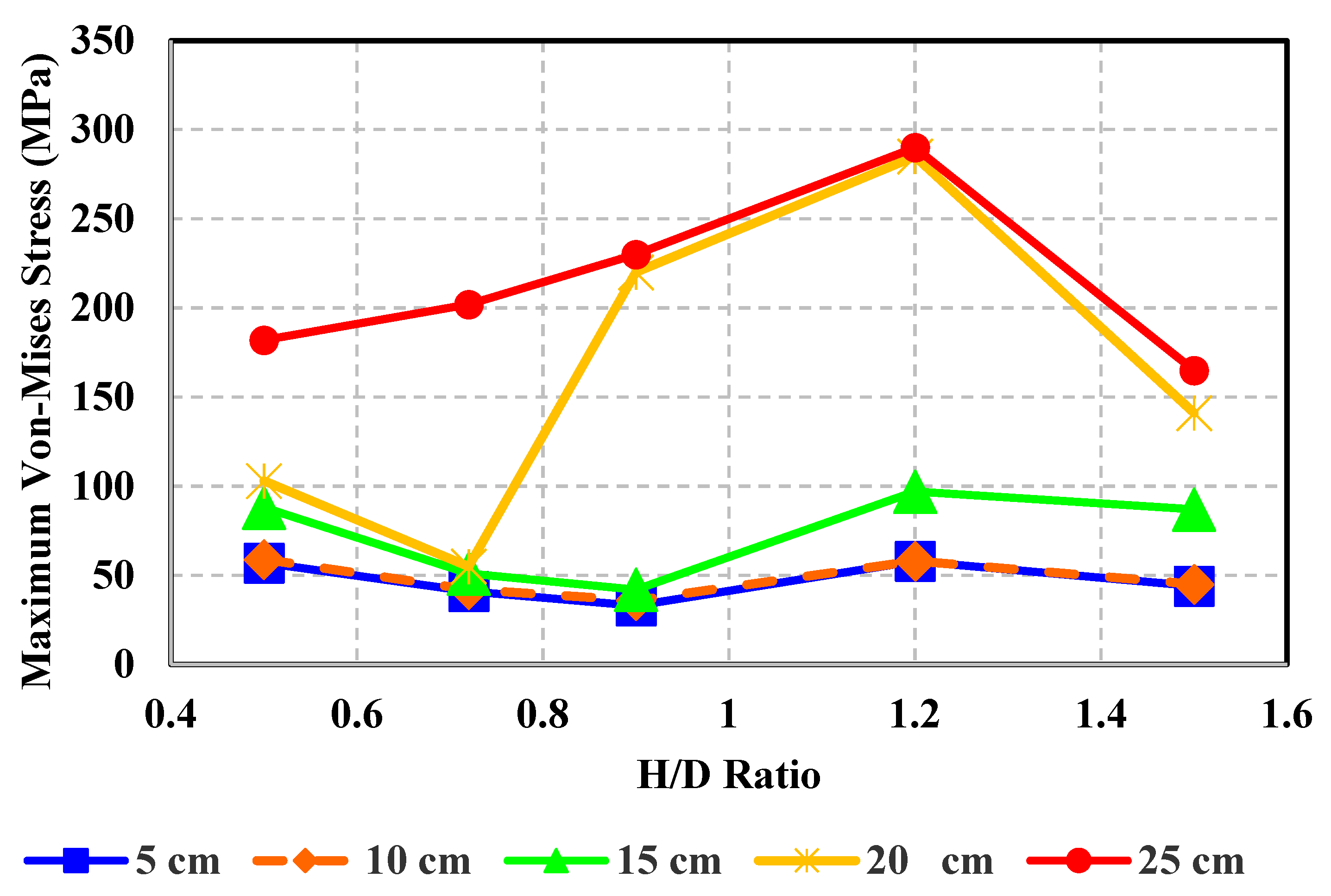
Figure 22 shows the stable and unstable loading points for each tank model. At a 25 cm amplitude, the maximum stress line increases linearly with the increase in H/D ratio due to an increase in convective frequency. However, at an H/D ratio of 1.5, it suddenly drops due to the column behavior of the tank. At a high fill level, the slender tank (D < H) acts as a column because of the low convective mass participation factor (less than 20%) and high impulsive mass participation factor (greater than 80%), as shown in
Figure 15.
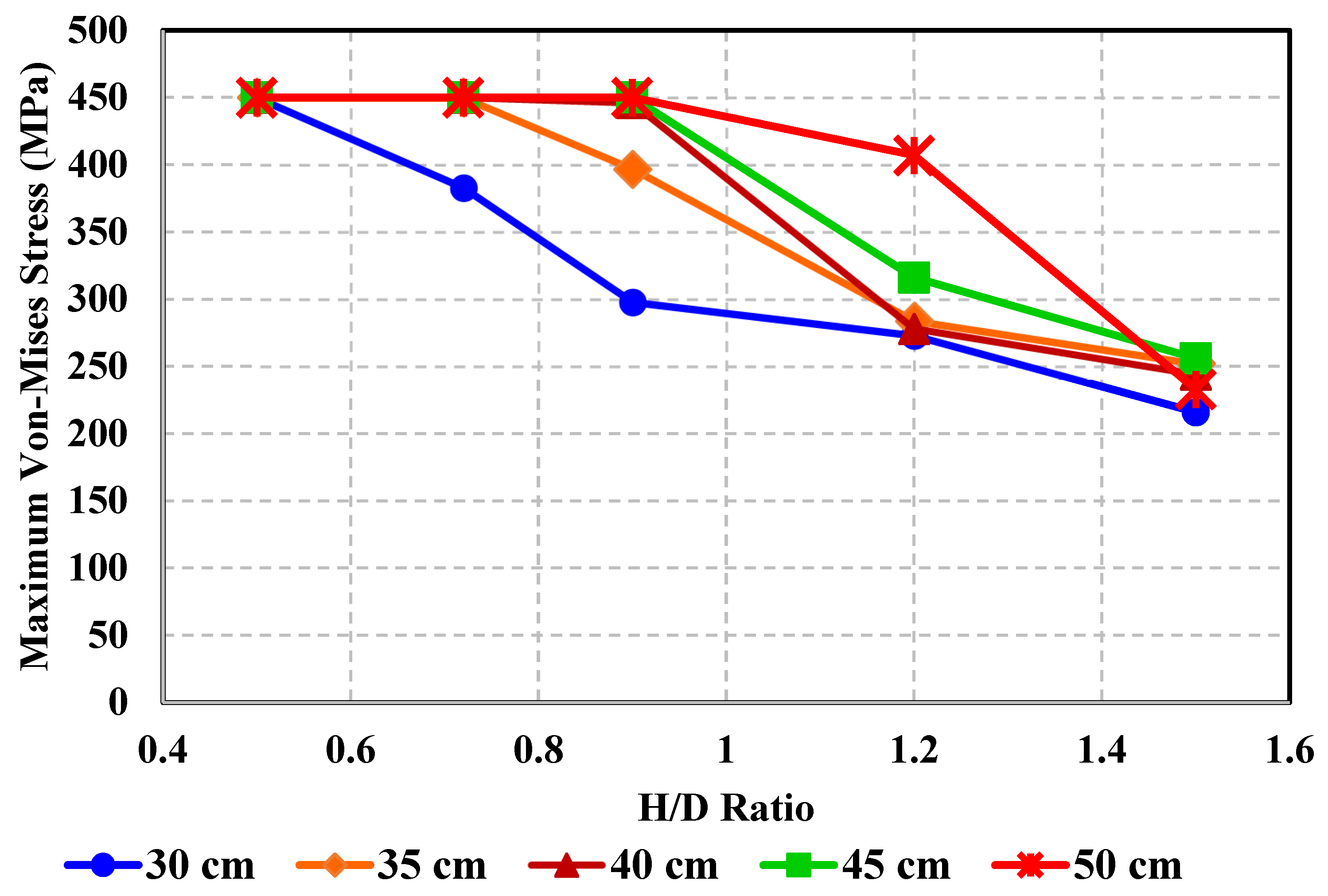
Figure 23 indicates the yielding and ultimate loading points. At a displacement amplitude of 30 cm, the maximum stress decreases linearly with an increase in the H/D ratio. It is observed that this linear behavior gradually changes to asymptotic with the increase in displacement amplitude.
Figure 24 indicates different zones and critical displacement loadings with respect to the structural response of five tank geometries. For an H/D ratio of 1.5, it is at 35 cm, whereas for an H/D ratio of 1.2, it is at 20 cm when excited at 3.142 and 2.808 rad/s (convective frequencies), respectively. For H/D ratios of 0.9, 0.72, and 0.5, the critical loadings at 30 cm of displacement amplitude are excited at 2.422, 2.146, and 1.721 rad/s, respectively.
Critical loadings equivalent to PGA for H/D ratios of 1.5 and 1.2 are 0.35 g and 0.16 g, respectively. For H/D ratios of 0.9, 0.72, and 0.5, the critical loadings are 0.18 g, 0.14 g, and 0.09 g, respectively. The board tank fails at a lower PGA than the slender tank, but it has to experience larger displacement amplitudes when excited at convective resonance than the slender tank. In terms of displacement amplitude excited at the tank’s first convective frequency, the critical value is between 25 and 30 cm, at which the slender and broad tank behaves structurally similar as the four tank curves (1.2, 0.9, 0.72, and 0.5) intersect with each other between 25 and 30 cm, and as the tank diameter increases from 4.6 m to 6.1 m, the intersection point moves towards 30 cm. When the diameter increases further to 7.6 m and 10.97 m, the intersection point moves back horizontally towards 25 cm, as shown in
Figure 24.
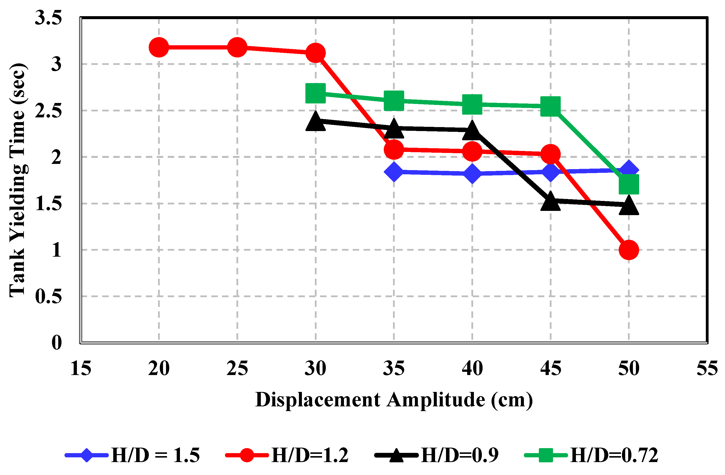
The yielding time for a tank with an H/D ratio of 1.5 remains almost constant but exhibits yielding earlier. In the case of an H/D ratio of 1.2, it yields at 3.18 s, which remains constant between 20 and 30 cm; this shows that the tank structure resists lateral excitation for 3 s up to a displacement amplitude of 30 cm. Between 35 cm and 45 cm, this time reduces to about 2 s upon further increase (i.e., at 50 cm, the yielding times decrease to 1 s). For H/D ratios of 0.9 and 0.72, the yielding time came a bit earlier (2.4 and 2.7 s, respectively), which drops down to 1.5 and 1.7 s at a 50 cm amplitude.
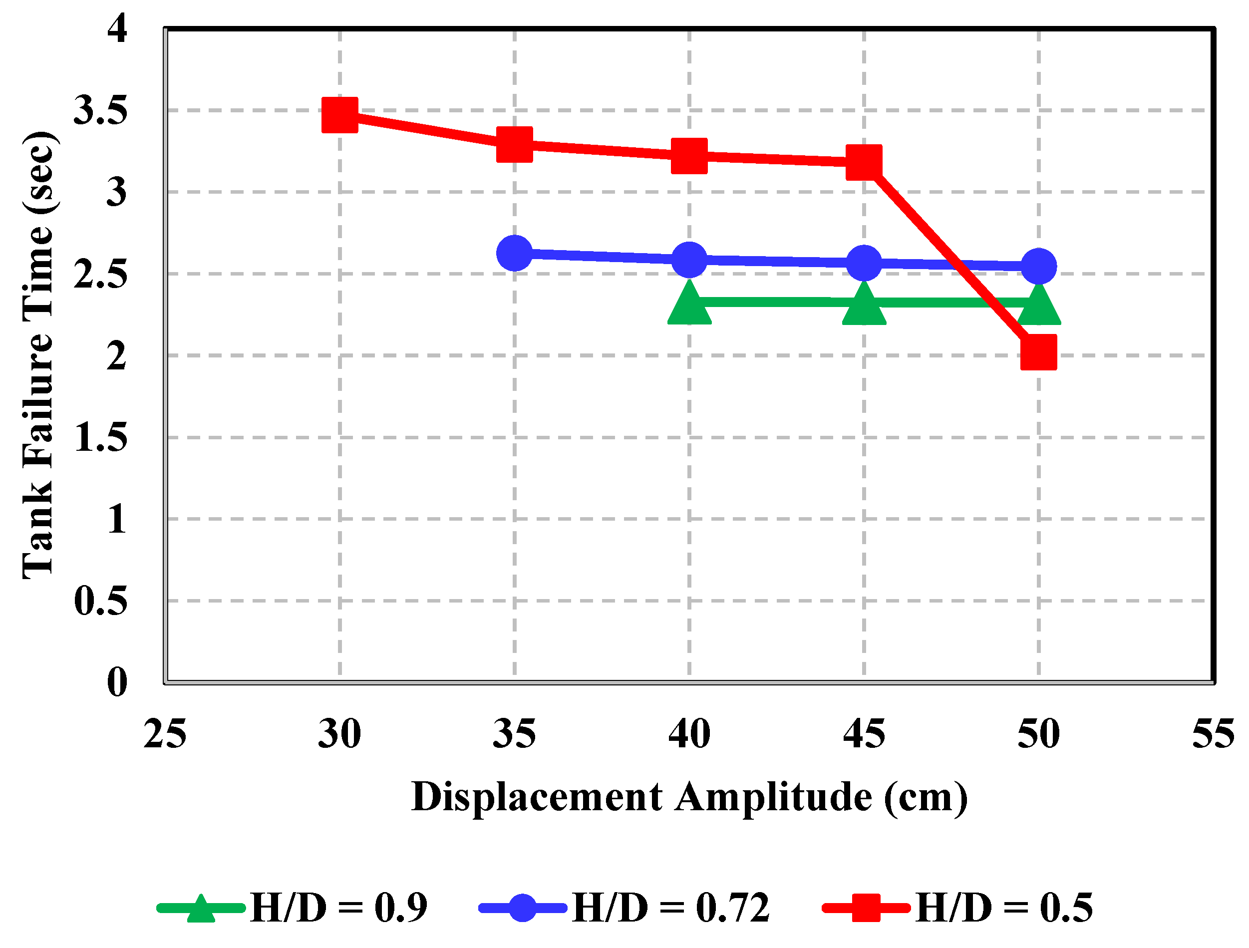
Similarly, the tank failure times at H/D ratios of 0.9 and 0.72 are 2.32 s at 40 cm and 2.63 s at 35 cm and onwards, respectively. For a broad tank (H/D ratio of 0.5), the failure time decreases about 1.7 times between 30 cm and 50 cm. The variation in yielding and failure time with displacement amplitude has been shown in
Figure 25 and
Figure 26.
4. Conclusions
The main focus of this article is to study and analyze the seismic behavior of ground-supported cylindrical steel tanks subjected to various displacement loadings excited at the first convective frequency. These displacement loadings are applied at the tank base. Several analyses have been performed with different displacement amplitudes starting from 5 cm to 50 cm (with an interval of 5 cm), which represent peak ground values of particular seismic activity. Five tank geometries with different aspect ratios are considered, which cover slender, medium, and broad tanks. At convective resonance, the structural behavior has been studied using modal and two-way fluid structural analyses. The seismic response curves and critical loads have also been evaluated. The major outcomes are as follows:
The tank’s structural behavior and response under resonant seismic sloshing vary with the H/D ratio as the convective frequency of the contained fluid increases with the increase in the H/D ratio of the tank. Similarly, as the H/D ratio increases, the impulsive mass participation factor increases, whereas the convective mass participation factor decreases asymptotically.
Tanks with H/D ratios of 1.5, 1.2, and 0.5 are structurally stable up to 10 cm, whereas tanks with H/D ratios of 0.9 and 0.72 are structurally stable at 15 and 20 cm displacement amplitudes, respectively.
Under resonant seismic excitations, the fluid-containing structures undergo three transitional stress zones (safe, yielding, and failure), which are indicated in the seismic response curves of each tank.
At a displacement amplitude of 30 cm, as the H/D ratio increases, the maximum structural stress decreases linearly; this linear behavior changes to asymptotic with an increase in displacement amplitude.
The structural response curve indicates that the slender and broad tanks behave structurally similarly between a displacement amplitude of 25 and 30 cm; therefore, at convective resonance, this displacement amplitude is critical for each tank type.
The critical loading of each tank geometry in terms of equivalent peak ground acceleration (PGA) is as follows: for H/D ratios of 1.5 and 1.2, they are 0.35 g and 0.16 g, respectively; for H/D ratios of 0.9, 0.72, and 0.5, they are 0.18 g, 0.14 g, and 0.09 g, respectively.
The critical load of the slender tank is four times greater than that of the broad tank due to the column behavior of the slender tank.
The yielding duration of the tank with an H/D ratio of 1.2 decreases in a staired pattern and exhibits a three-fold reduction at a displacement amplitude between 20 and 50 cm.
The yielding duration of broad tanks (i.e., H/D ratios of 0.9, 0.72, and 0.5) is reduced 1.6-fold and 1.7-fold when excited between displacement amplitudes of 30 to 50 cm.
The above-mentioned findings will help in understanding the highly complex and nonlinear behavior of ground-supported steel tanks under resonant seismic sloshing. The effect of variation in the H/D ratio on convective frequency, mass participation factors, maximum equivalent stress, and seismic sustainability duration has been studied, and structural response curves have been developed. Critical loadings are calculated in terms of yielding and ultimate failure, along with the evaluation of yielding and failure durations. To avoid future structural damage, the tank may be designed based on evaluating critical loadings. This study is limited to above- or ground-supported cylindrical steel tanks subjected to lateral seismic excitations excited at the first convective frequency.
For future studies, different tank geometries, i.e., rectangular or conical, are needed to be considered for the study of their structural response by evaluating critical loadings and failure times. Similarly, the loading type may also be changed, i.e., vertical or a combination of both horizontal and vertical ground motion, to study the structural seismic response.

 ,
, 


