1. Introduction
Natural fibers reinforced composites gained popularity in various engineering applications and were proposed as a realistic alternative to glass fibers in polymer composite reinforcement. Flax, jute, sisal, and other natural fibers are environment-friendly [
1,
2,
3]. They have relatively high specific strength and modulus due to their low density. From a manufacturing point of view, these fibers are low cost, non-abrasive to processing equipment, cause no irritation, present less health risk, and lower energy consumption during fiber preparation and composite molding [
4,
5,
6,
7,
8,
9,
10,
11,
12,
13,
14].
Carbon fibers are more popular than natural fibers in many fields of application due to their mechanical performance and excellent energy absorption capacity [
15,
16]. However, carbon fibers and their composites are more expensive than most other fibers reinforced polymers. Additionally, carbon composite ductility is limited by the intrinsic brittleness of the fibers and stress concentrations [
17,
18,
19,
20,
21,
22,
23,
24,
25,
26,
27,
28,
29,
30,
31,
32,
33,
34,
35,
36,
37,
38,
39,
40].
Natural fiber composites attract growing interest in automotive applications, which remain the largest market through 2016 [
19,
20,
21]. Several automotive components are now produced using natural fiber composites; door panels, package trays, hat racks, instrument panels, internal engine covers, sun visors, boot liners, and oil/air filters [
22]. However, concerns about their strength, stiffness, and resistance to moisture absorption lead to higher water uptake and degradation of mechanical performance.
Recently, the hybridization of natural fibers with synthetic fibers such as carbon [
23,
24,
25,
26,
27,
28] and glass [
26,
29,
30,
31] has increased interest. Carbon or glass fiber composites have higher mechanical properties and water absorption resistance than natural fiber composites. Hybridization balances reasonable costs and optimal performance to extend their applications. In general, the purpose of bringing two fiber types in a single composite is to maintain the advantages of both fibers and alleviate some disadvantages. In hybrid composite, mechanical properties depend on each fiber content, length, orientation, fibers to matrix interface, and dependent on individual fibers’ failure strain.
Hybrid optimal mechanical properties can be obtained by mixing high-strain compatible fibers [
32]. However, applying tensile load in the fiber direction will cause more brittle fibers to fail before the more ductile fibers. Moreover, in the case of carbon laminate, substituting the middle plies with cheaper fibers can significantly reduce its cost without affecting the flexural properties [
33].
In this research, hybrid carbon/flax fiber-reinforced epoxy laminates were fabricated by stacking unidirectional fibers that were impregnated by resin transfer molding. Quasi-static mechanical tests characterized hybrid composites to investigate tensile and flexural behavior as a function of laminate hybridization rates. Acoustic emission was used to monitor the evolution of internal and non-visible damage. The acoustic signals were classified using the K-means method, analyzed, attributed to tensile and flexural induced damage, and discussed based on their contribution to highlight the effect of hybridization.
2. Materials and Experiments
The unidirectional flax tapes used in this study were supplied by LINEO (Valliquerville, France), with an areal density of 110 g/m2. Flax fibers are characterized by Young’s modulus of 72.9 GPa and strength of 742 MPa (data provided by the supplier). The unidirectional carbon fabrics, with an areal density of 120 g/m2, were supplied by Fibre Glast Developments Corp. (Brookville, OH, USA). The matrix consists of an 820 epoxy/824 hardener system provided by Adtech Plastic (Charlotte, MI, USA) and mixed to the hardener/resin ratio (18/100) recommended by the supplier.
Table 1 presents the studied composites. Non-hybrid and hybrid laminates were produced by resin transfer molding. Fiber layers are stacked in a heated steel mold with a 3 mm cavity thickness and installed in a hydraulic press. After resin injection, the composite panel is left in the mold to cure at 70 °C and a pressure of 5 bars for 2 h.
ASTM D3039 and ASTM D790 were followed for tensile and flexural testing of laminates. Test specimens were cut using an abrasive waterjet machine. Tests were performed using a 100 kN MTS universal testing machine at a 2 mm/min fixed loading rate. Five experiments were conducted for each laminate.
A two-channel AE system supplied by Vallen (Wolfratshausen, Germany) with a sampling rate of 5 MHz and a 40 dB pre-amplification was used to monitor the damage. The AE measurements were performed using KRNm300 sensors (KRN Services, Richland, WA, USA). High vacuum silicon grease was used to connect the sensors and the specimen surface. Load, strain, and head displacement data were fed to the Vallen system and recorded at a 10 Hz sampling frequency. A pencil lead break test was used to calibrate the data acquisition system and ensure good conductivity between the specimen surface and the sensors.
3. Results and Discussion
3.1. Effect of Hybridization on Mechanical Properties
3.1.1. Tensile Mechanical Properties
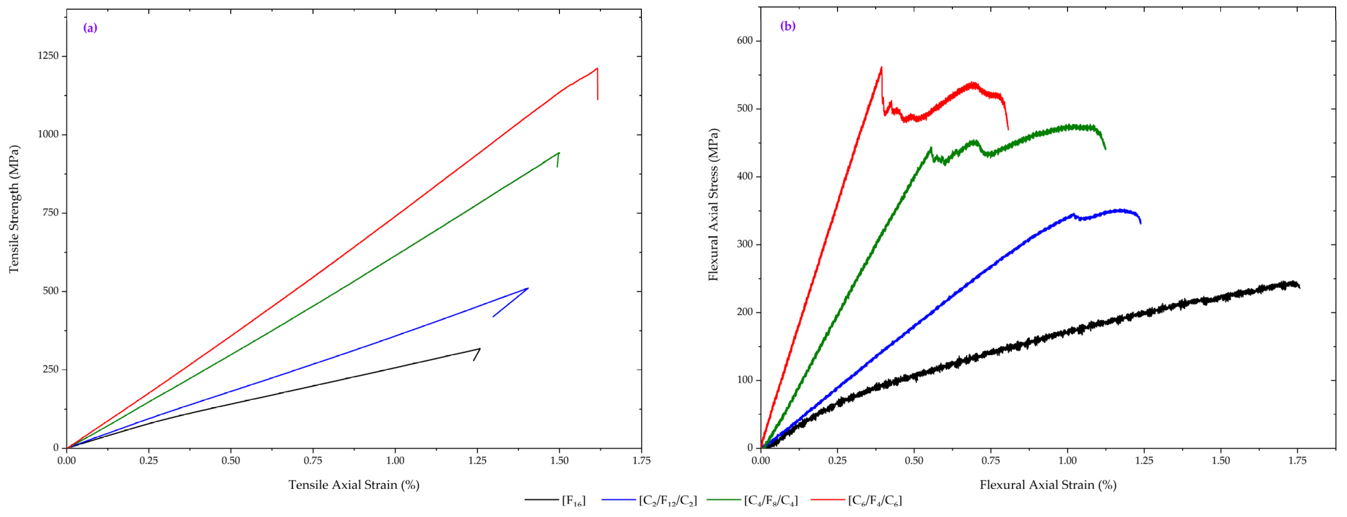
Figure 1a shows typical tensile load–strain curves of the studied composites.
Table 2 presents the obtained results of mechanical properties. It can be seen that the average tensile strength and modulus have approved a significant effect of hybridization. A proportionate increase in tensile properties was observed when the carbon fiber content increased. With stronger properties than natural fibers, the hybridization of carbon and flax provided stiffer material with significantly improved mechanical properties.
A non-linear elastic tensile behavior characterizes natural fibers, while synthetic fibers, on the other hand, have near-linear elastic tensile behavior. From the load–displacement curves of
Figure 1, the increase in the hybridization rate, with the increase in the carbon fiber content, increases the linear elastic tensile behavior of the composite. A linear elastic tensile response was achieved as carbon fiber is dominant in the [C
6/F
2]
s hybrid composite. In contrast, flax composite ([F
16]) shows a non-linear elastic behavior.
Table 2.
Tensile properties of studied laminates.
Table 2.
Tensile properties of studied laminates.
Laminate
Designation | Vf(C/F) | E (GPa) | σ (MPa) |
|---|
| [F16] | 0/40.46 | 30.48 ± 2.32 | 312.51 ± 3.19 |
| [C2/F6]s | 10.41/30.34 | 41.58 ± 2.56 | 510.36 ± 10.71 |
| [C4/F4]s | 20.82/20.23 | 66.53 ± 4.25 | 949.13 ± 4.47 |
| [C6/F2]s | 31.24/10.11 | 75.25 ± 2.35 | 1196.50 ± 19.43 |
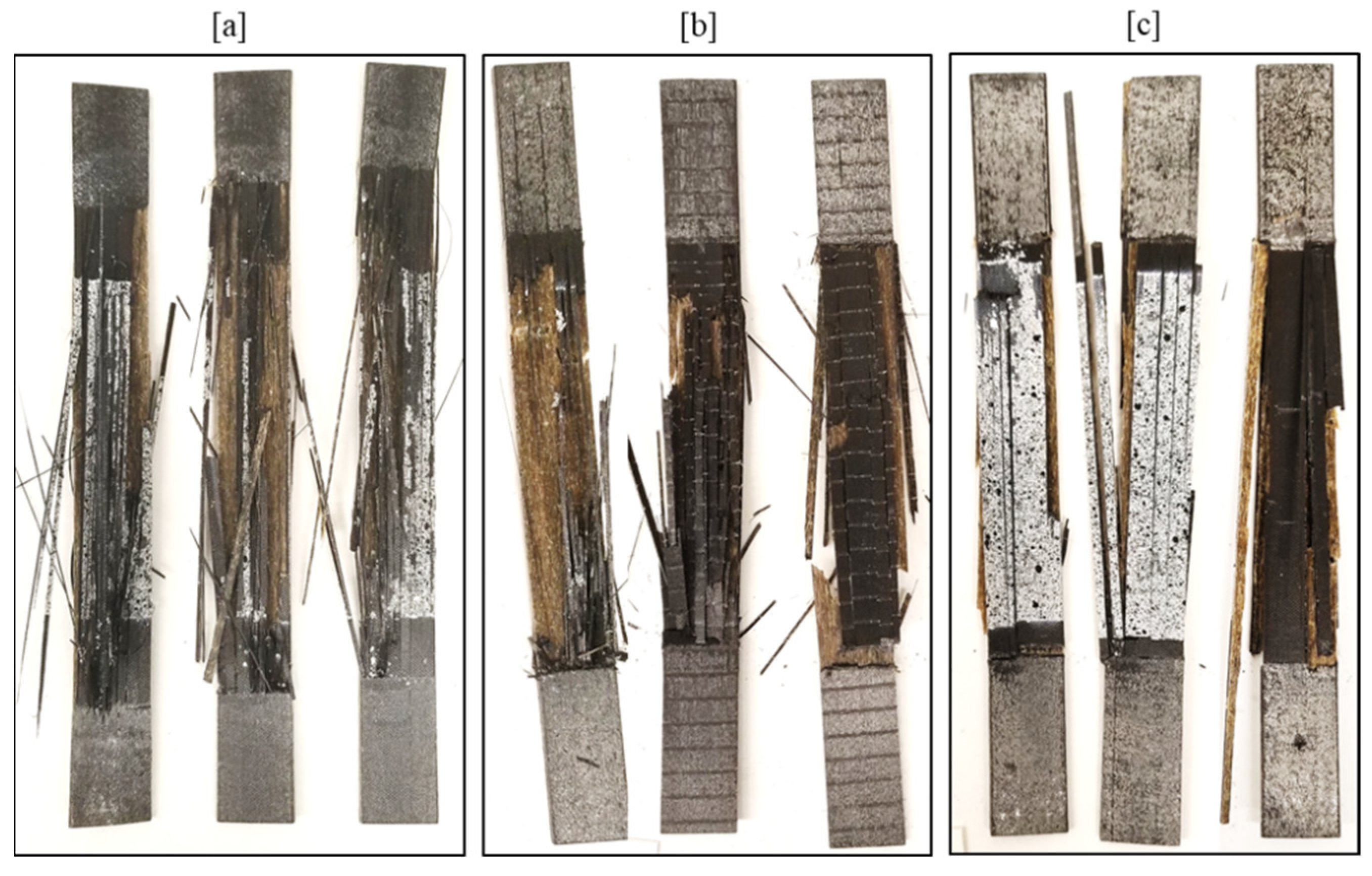
Visual inspection of tensile fractured specimens provided valuable information about composite failure modes, such as delamination and fiber breakage, which discuss the effect of hybridization.
Figure 2 showcases the fractured samples of different hybrid composites, providing valuable insights into the failure modes influenced by hybridization. Visual inspection of the tensile fractured specimens reveals important information about the composite’s failure behavior, specifically delamination and fiber breakage.
The principal observed failure mode depicted in
Figure 2 is the rupture of the outer carbon layers, which exhibits a brittle fracture behavior. These carbon layers break in a brittle manner and subsequently debond from the flax layers. This distinctive failure mode can be attributed to the lower strain-to-failure of the carbon fibers, resulting in a typical catastrophic fracture with an abrupt failure of the hybrid composite.
The fractured samples in
Figure 2 serve as visual evidence of the interplay between different layers within the composite material. They illustrate the complex failure mechanisms associated with hybridization, including the role of carbon layers and their interaction with the flax layers.
3.1.2. Flexural Mechanical Properties
Figure 1b shows the flexural load–strain curves of the studied composites, and
Table 3 presents the resulting properties. The results revealed that the increase in the hybridization rate exhibits improvement in flexural strength and modulus. The improvement in the flexural properties was accompanied by a decrease in elongation at break compared to flax composites.
Similar to tensile behavior, the load–strain curves for hybrid composites were more linear, with a small non-linear region near the maximum flexural strength and before a sudden load drop after a second peak load. For flax composite, the load–strain curves show a non-linear behavior with a higher elongation at break.
Figure 1b shows that the non-hybrid laminates [F
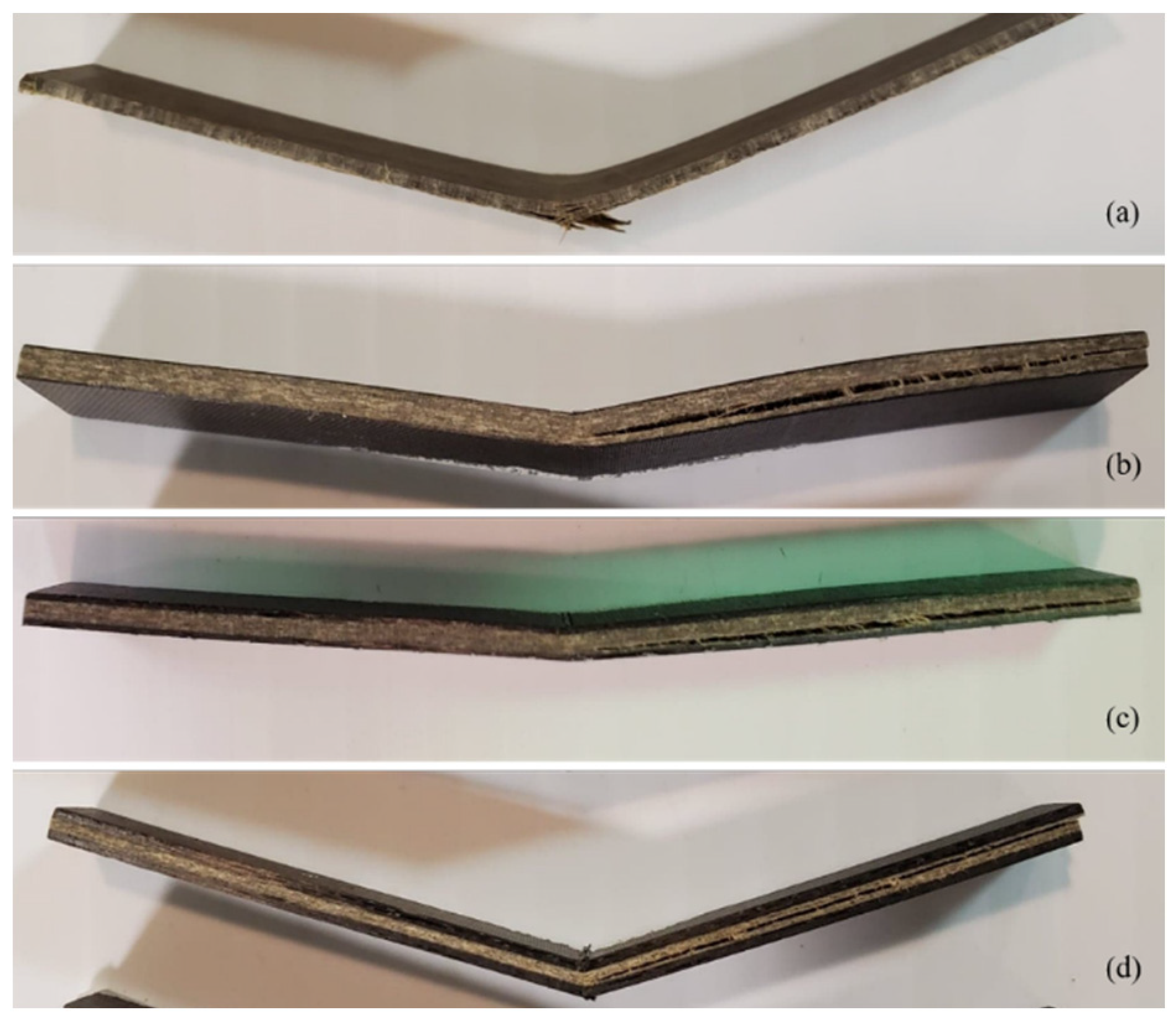
16] show abrupt stress drops without any significant sequential stepwise decrease. Additionally, examining the fractured samples of
Figure 3a allows us to conclude that the tensile load at the lower half of the sample has provoked damage initiation. Moreover, it has triggered fiber breakage and delamination, conducting to abrupt composite failure.
Nevertheless, all hybrid composite samples have somewhat similar fracture behavior. Visible delamination is observed in
Figure 3b–d.
Due to the difference in the stiffness of the constitutive flax and carbon plies, identifying failure mechanisms becomes more complicated. Fundamentally failure starts from top or bottom plies due to higher stress states, wherein the plies stiffness will significantly influence damage development.
In the case of a low hybridization rate,
Figure 3b,c allow concluding that the carbon bottom plies do not present any form of damage. This observation also indicates that damage is located only in the upper half of the specimen. So, buckling is the only observed damage at the top plies of both [C
2/F
6]
s and [C
4/F
4]
s samples. These samples show a kink band formed at the upper carbon plies, but the developed failure does not advance in the flax layers.
This finding may allow concluding that the first stress drop in the stress–strain curve is related to buckling. To determine whether the development of buckling and propagation of the kink band is correlated with the stepwise decline in stress, it is necessary to discuss the relation between buckling and delamination. In the case of the [C
6/F
2]
s, with the higher hybridization rate,
Figure 3d shows a more pronounced development of buckling at the top carbon plies. Here, the compressive failure of carbon fibers starts from the surface and develops as a shear-driven failure. Consequently, the propagated shear-induced failure brought the interlaminar delamination extension. In that case, interlaminar delamination competes with kink bands and shear-induced failure.
4. Damage Characterization during Mechanical Tests
4.1. Clustering of Acoustic Emission Data
Acoustic emission monitors the progressive damage during tensile and flexural testing of the different composite samples to characterize the various failure mechanisms.
Since the overall task of the method is to detect the most significant clusters of the entirety of acoustic emission signals, with a minimum of initial assumptions on the cluster structure, we made no assumptions on the exact number of signal classes or their type.
The K-means algorithm is one of the most used algorithms to signal classification based on its features. However, AE signal features such as peak amplitude, count, and duration depend significantly on the type of sensor, the specimen geometry, and constitutive materials properties or the propagation distance between the source and sensors. Consequently, the signal classification methods are adaptive to the problem investigated and do not rely on generalized ranges similar to the results of various research groups.
In this section, the AE signal classification was achieved in two phases. The first phase is the statistical data analysis, which is used to form signal groups. The second phase attempts to correlate each group with a particular damage mechanism. Here, the Davies–Bouldin index (DB) is used to determine the optimal cluster number to be used for clustering.
Since the K-means clustering algorithm and the Davies–Bouldin index are comprehensively described in many publications [
34,
35,
36], they are not explicitly detailed in this section.
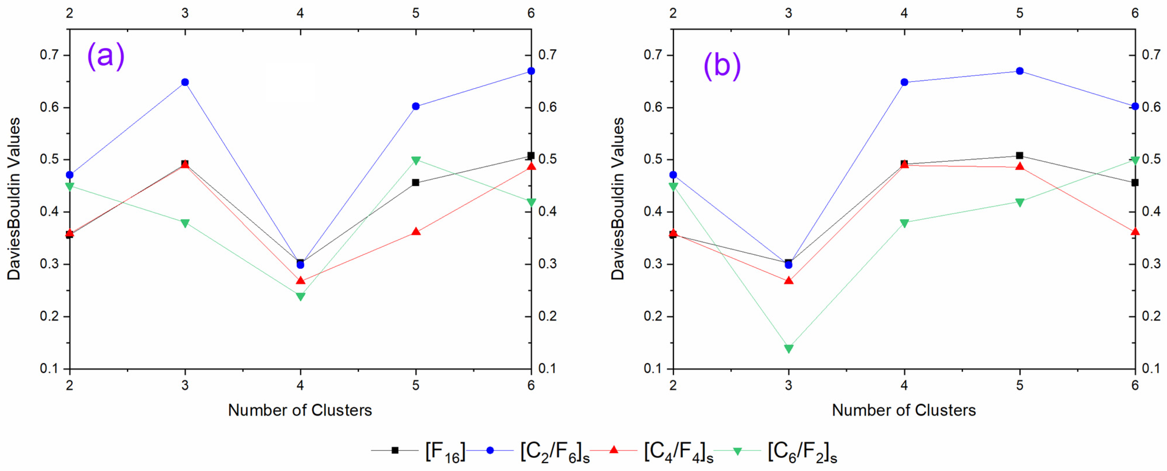
According to the minimum values of the DB index, optimal clustering is obtained with four classes for all tensile tests of composite samples, as shown in
Figure 4a. Similarly, good partitions of flexural AE signal suggest a different optimal cluster number than tensile tests. Following the minimum values of the DB index, flexural composite failure can be discussed based on three clusters, as shown in
Figure 4b.
4.2. Damage Characterization in Tensile Tests
4.2.1. Tensile AE Signal Clustering and Damage Mechanism Attribution
Due to their excellent repeatability, only the test results of one specimen of each composite are shown in the following figures. The K-means clustering method is applied to three distinct acoustic signals derived from three distinct tensile tests of each composite.
Table 4 presents the results of clustering considering the signal amplitude, the number of counts, and the signal duration for different clusters. Feature ranges are shown using the mean value and the standard deviation calculated based on 12 ranges of clustering results for the four composites. Based on previous results of the DB index, the detected acoustic emission signals could be assigned to matrix cracking, fiber debonding, delamination, and fiber breakage.
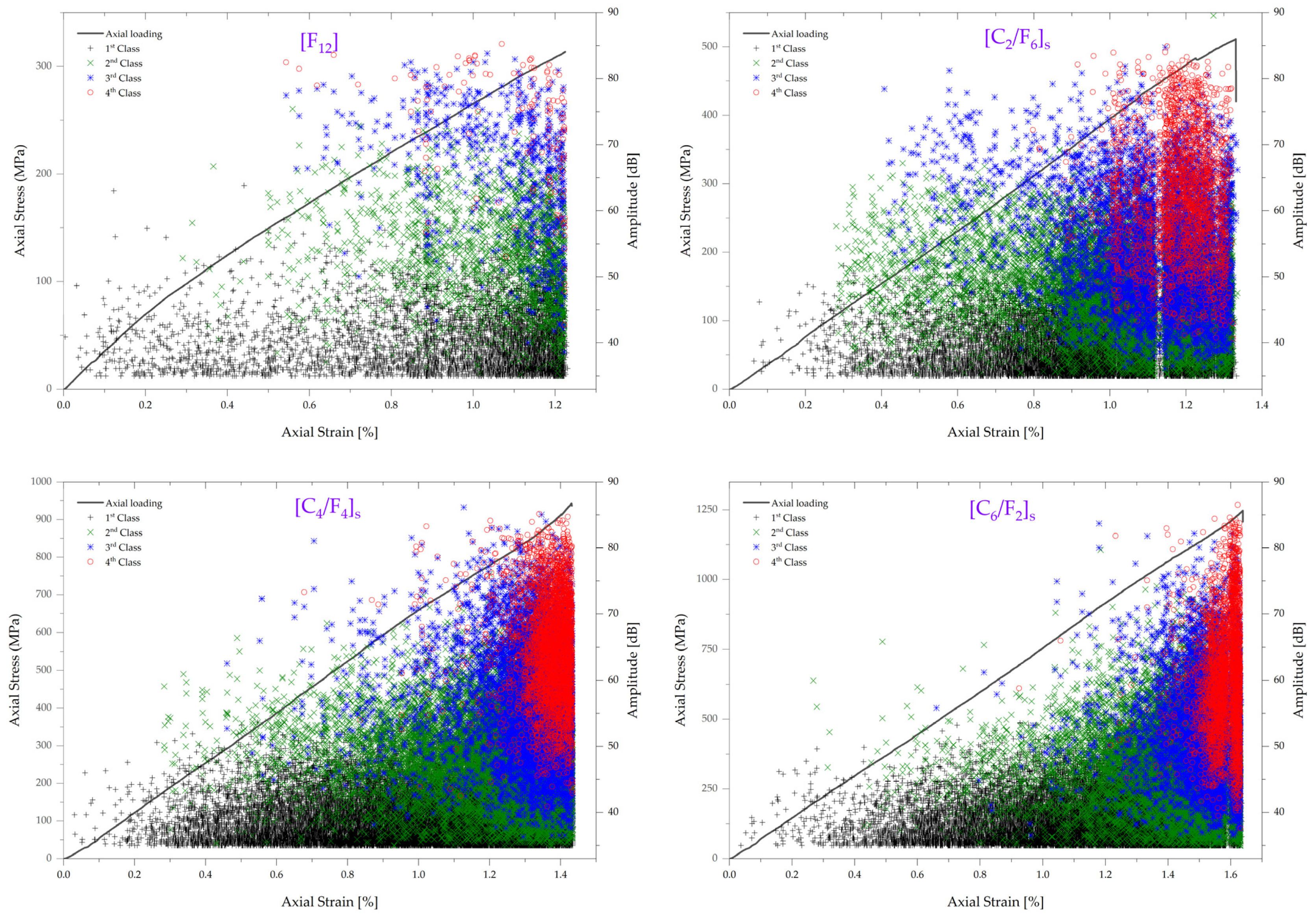
Figure 5 shows one representative classification result for one specimen of each composite. With the application of a load on all composite specimen types, acoustic emission signals initiate by a first-class of acoustic signals with an amplitude ranging between 35 dB and 65 dB. Although they originate from failure at the specimen edges or failure at resin-rich areas, these signals can be classified as matrix cracking.
At a distinct load level, signals classified as second- and third-class with an amplitude ranging between 35 dB and 75–85 dB are likely associated with interfacial damage [
37]. However, the distinction between fiber debonding and delamination is hardly justified in the present case. In this case, the AE signals waveform is used to deal with an impartial distinction between these two classes.
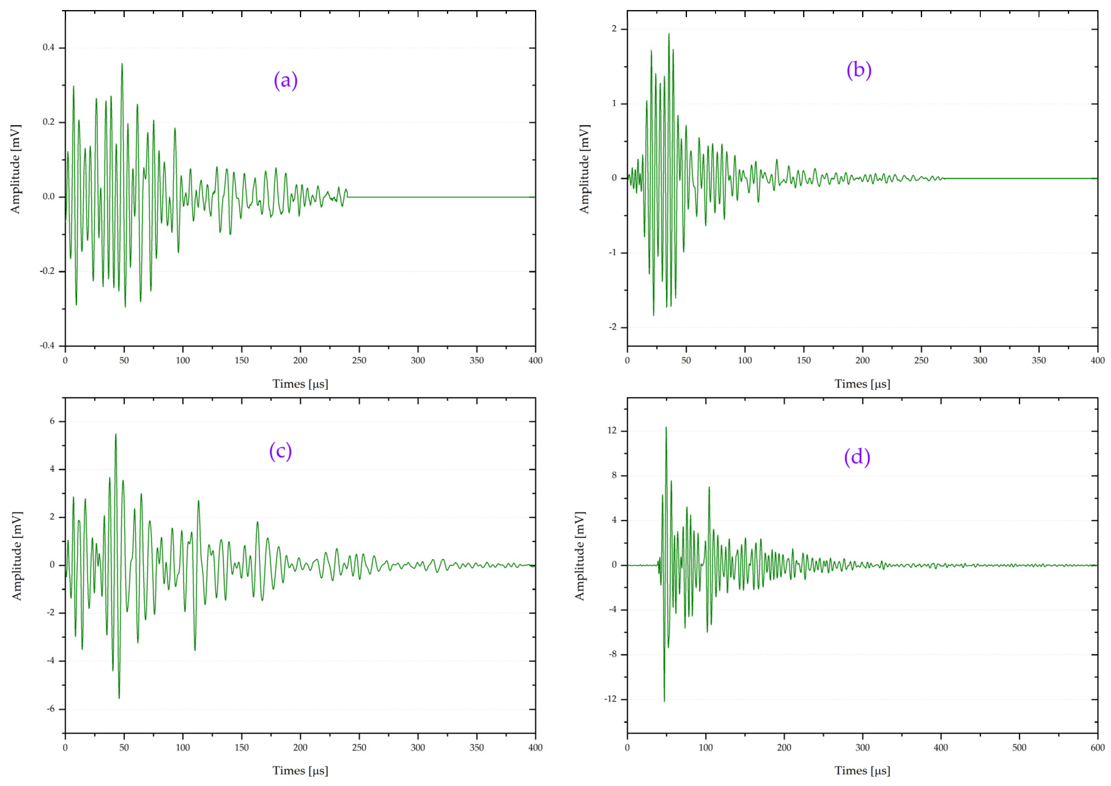
Figure 6 presents a representative typical acoustic waveform for the four class types. The four waveforms are different. The amplitude of the matrix cracking waveform is low and changes slowly with time, as shown in
Figure 6a. Therefore, the waveform confirms the attribution of the first-class signals to matrix cracking.
By comparing the waveforms of the second-class (
Figure 6b) and third-class (
Figure 6c) signals, it can be seen that the waveform of the third-one has a higher amplitude and multiple peaks. Therefore, the distinction is made between these two classes by attributing the second-class signals to fiber debonding. In the following, all signals of the third class, localized within the range of 38 dB to 85, are attributed to delamination.
As predicted by the generalized theory of acoustic emission and confirmed by the waveform of
Figure 6a,d, the first and fourth acoustic signal classes are qualified as matrix cracking and fiber breakage. By analyzing the waveform of matrix cracking in
Figure 6a, it can be seen that the waveform has the lowest amplitude.
By analyzing the waveform of fiber breakage in
Figure 6d, it can be concluded that this class of signals occurs suddenly and have a shorter rising time and larger amplitude, where the energy rapidly ranges at a high level and then rapidly falling-off.
Since acoustic signals were classified into four distinct classes and attributed to different damage mechanisms,
Figure 5 can be used to discuss the development and severity of damage inside the different composite samples in the whole tensile failure process.
4.2.2. Description of Damage Evolution in Tensile Loading of Composites
In the case of flax composite ([F16]), acoustic emission signals associated with matrix cracking appear in a relatively low strain range. Subsequently, matrix cracking progression keeps constant evolution during specimen loading before a particular intensification at around 82% load to failure. However, hybridization induces a noticeable change in the matrix cracking initiation. The average onset is at a distinct load level, which seems close to the ultimate tensile strength of the pure matrix material (60–70 MPa). After that, the number of matrix cracking signals increases as the tensile load increases. Notably, acoustic activity increases proportionally to load at a strain level of about 0.35–0.4%. This remarkable increase is mainly caused by an almost simultaneous onset of new damage mechanisms originating from fiber debonding and delamination. With increased loading, it is observed that the number of signals of these two classes dominates. As a second conclusion, it is possible to deduce that hybridization significantly affects their evolution. The accumulated signals corresponding to the two failure mechanisms show a substantial increase in the activity rate.
In contrast, the increase in the hybridization rate tends to condensate most of the signal near the ultimate tensile strain. Additionally, the distribution of fiber breakage signals shows a significant difference in the failure behavior of studied composites. Hybrid samples exhibit a substantial increase in the activity rate of fiber breakage signals. Therefore, their development is in good agreement with the development of fiber debonding and delamination. The average onset of fiber breakage signals is estimated at around 50% of the ultimate tensile load for all tested composites.
As seen in
Figure 5, the effect of hybridization on composite failures can be comprehensively and qualitatively assessed based on the evolution of the acoustic signals.
Therefore, the contribution of different damage mechanisms derived from the released energy of the various signals is meant to provide an improved possibility to compare and quantitatively interpret the failure of composites.
4.2.3. Contribution of Damage Mechanism in Tensile Failure
As has been shown in [
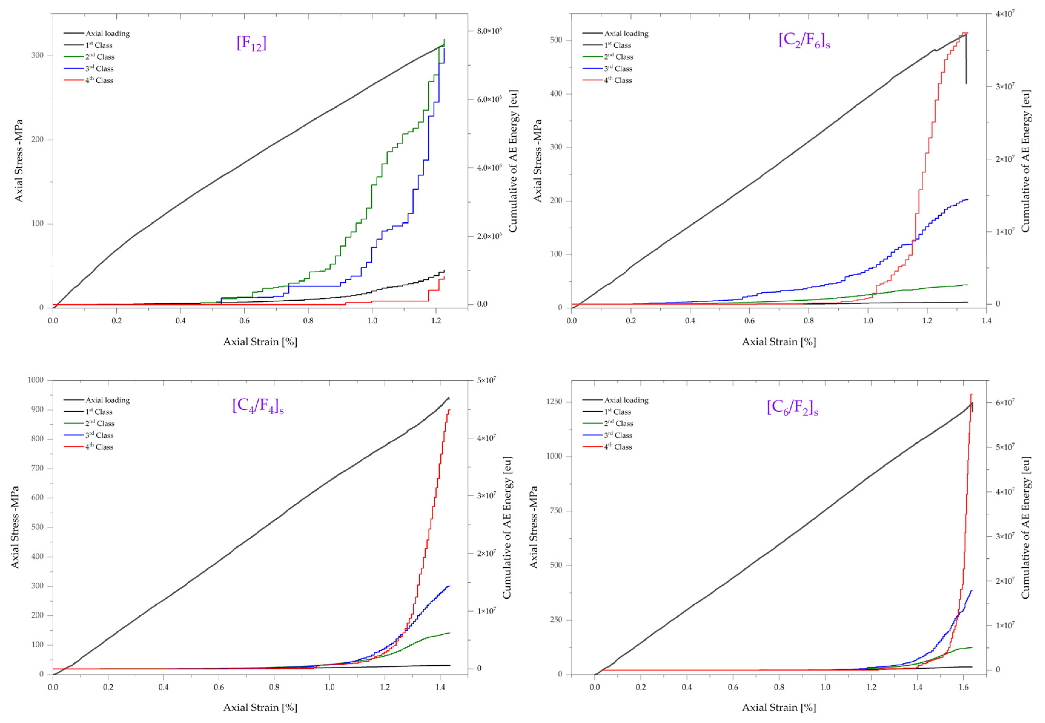
38], the contribution of each acoustic emission signal cluster is calculated based on specific and total accumulated energy, and it is enough to assess the damage evolution along with load application.
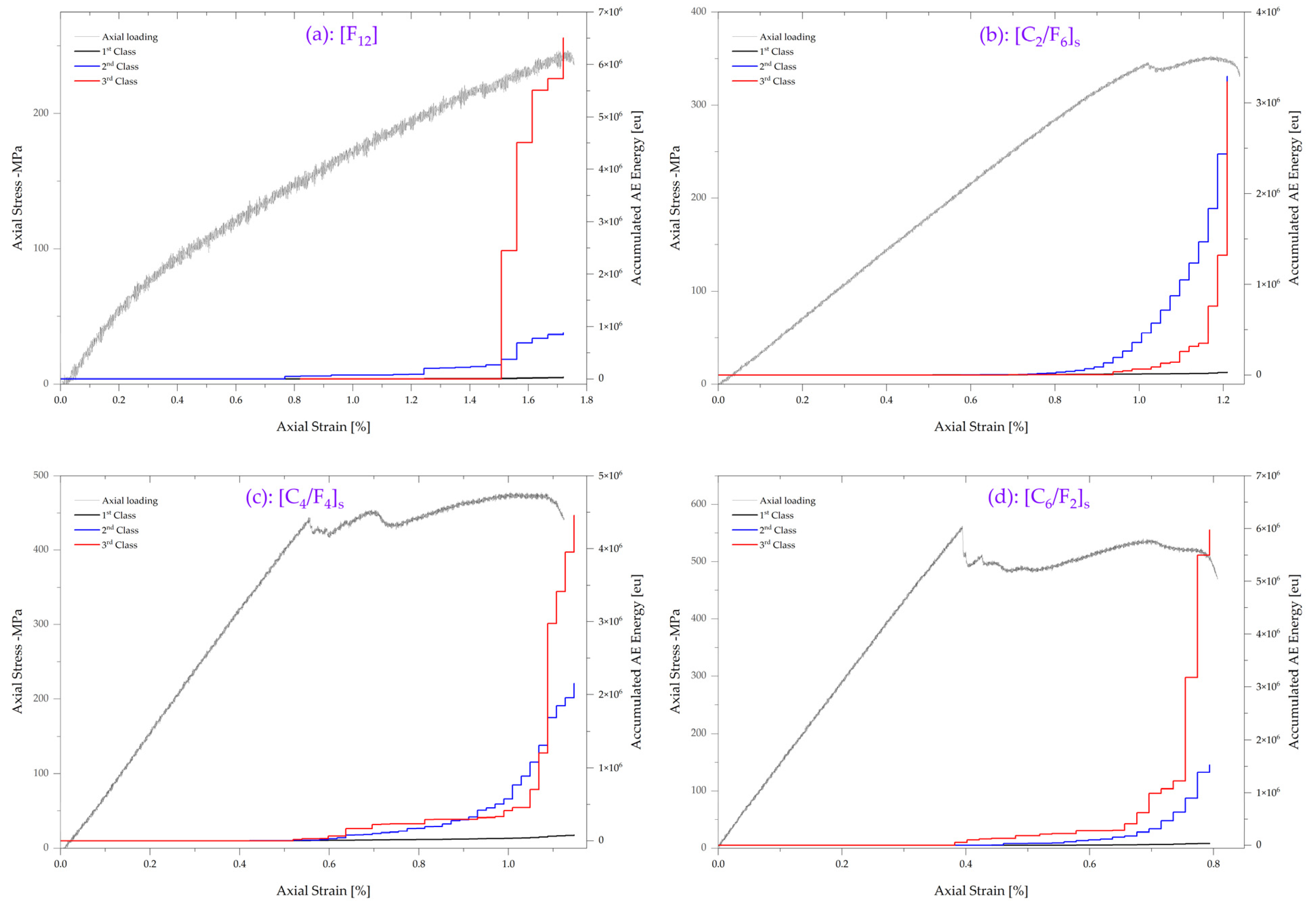
The load and accumulated AE energy versus strain curves for all signal clusters are shown in
Figure 7. Remarkably, the most relevant contribution of acoustic emission signals in the failure of flax composite ([F
16]) was assigned to the occurrence of signals classified as interfacial failure modes. The average contribution of fiber debonding and delamination signals is around 45.4% and 43.8%, respectively. Both clusters release significant energy signals at approximately 40% and 55% of the ultimate tensile strain, corresponding to 40% and 50% of the ultimate tensile strength.
After that, the accumulated AE energy of all damage mechanisms gradually increases, indicating that the damage inside the specimen intensifies. The relative contribution of matrix cracking and fiber breakage is found at equal levels between 5 and 6%.
Compared to flax composite, the accumulated AE energy of hybrid composites provides a significant difference in damage evolution. Here the specimen exhibits vast differences in delamination and fiber breakage growths, which will be further discussed in the following.
As presented in
Figure 2 of the fractured samples and confirmed by
Figure 5, the hybrid composites’ principal observed failure modes are delamination and rupture of the outside carbon layers. However, the accumulated AE energy of delamination and fiber breakage evolution contradicts our first generalized assumption. The outer carbon layers break brittle and then debond from the flax layers, especially in the [C
2/F
6]
s hybrid composite.
Based on the result in
Figure 7, the accumulated AE energy of delamination starts to increase earlier than in other composites, at a strain of around 0.4%, to grow significantly at 0.6%. After that strain, the delamination energy release rises proportionally to the applied load. The average onset of the intense fiber breakage energy release is seen later in strain, at about 0.9%, where it borrows a proportional increase to delamination. Accordingly, the detection of a critical growth of the fiber breakage energy release at 1.2% strain can conclusively indicate that the failure scenario introduced by the first assumption, based on the visual inspection of the fractured samples, is reversed. Thus, acoustic emission measurements of
Figure 7 clearly show that [C
2/F
6]
s hybrid composites are sensitive to delamination, especially before reaching around 70% of the ultimate tensile loading. For those cases of failure scenario, the global contribution of delamination and fiber breakage is about 26% and 68%, respectively. The accumulated AE energy of matrix cracking and fiber debonding reflects a limited damage contribution of 1% and 5%, respectively.
A comparison of the accumulated AE energy of acoustic emission signals in the case of the hybrid composites shown in
Figure 7 indicates that signal classes with significant contributions tend to stabilize and remain constant within strain ranges of 0.4% to 0.95% and 0.4% to 1.15%, for [C
4/F
4]
s and [C
6/F
2]
s, respectively. Again, the total released energy shows only minor contributions of 1% and 9% of matrix cracking and fiber debonding.
Looking more precisely into the contributions of individual delamination and fiber breakage mechanisms,
Figure 7 reveal an identical global evolution. Released energy by delamination increases like [C
2/F
6]
s and precedes the intensification of fiber breakage energy. By increasing the hybridization rate, the released energy increases proportionally to the carbon fiber content, characterized by higher energy release when broken. However, even the global energy release increases, delamination and fiber breakage mechanisms’ contribution remains equivalent to 20% and 70%, respectively. Additionally, minor contributions of matrix cracking and fiber debonding do not undergo a relevant change that will increase their contribution to the final failure of the hybrid composites.
The results of
Figure 7 may be further generalized with respect to the distribution of signals with the applied load. With increasing load, it is observed that the contributions of signal classes increase. More importantly, the increase in carbon fiber content tends to delay material damage and limits signals with significant contributions increasingly close to the ultimate tensile load, especially to the exponential rise in the fiber breakage signals.
4.3. Damage Characterization in Flexural Tests
4.3.1. Flexural AE Signal Clustering and Damage Mechanism Attribution
All acoustic emission signals acquired during mechanical testing of composite samples are clustered using the same approach adopted in tensile tests. The application of the Davies–Bouldin method yields three signal classes for all samples.
Table 5 presents the clustering results considering the three clusters’ signal amplitude, number of counts, and signal duration.
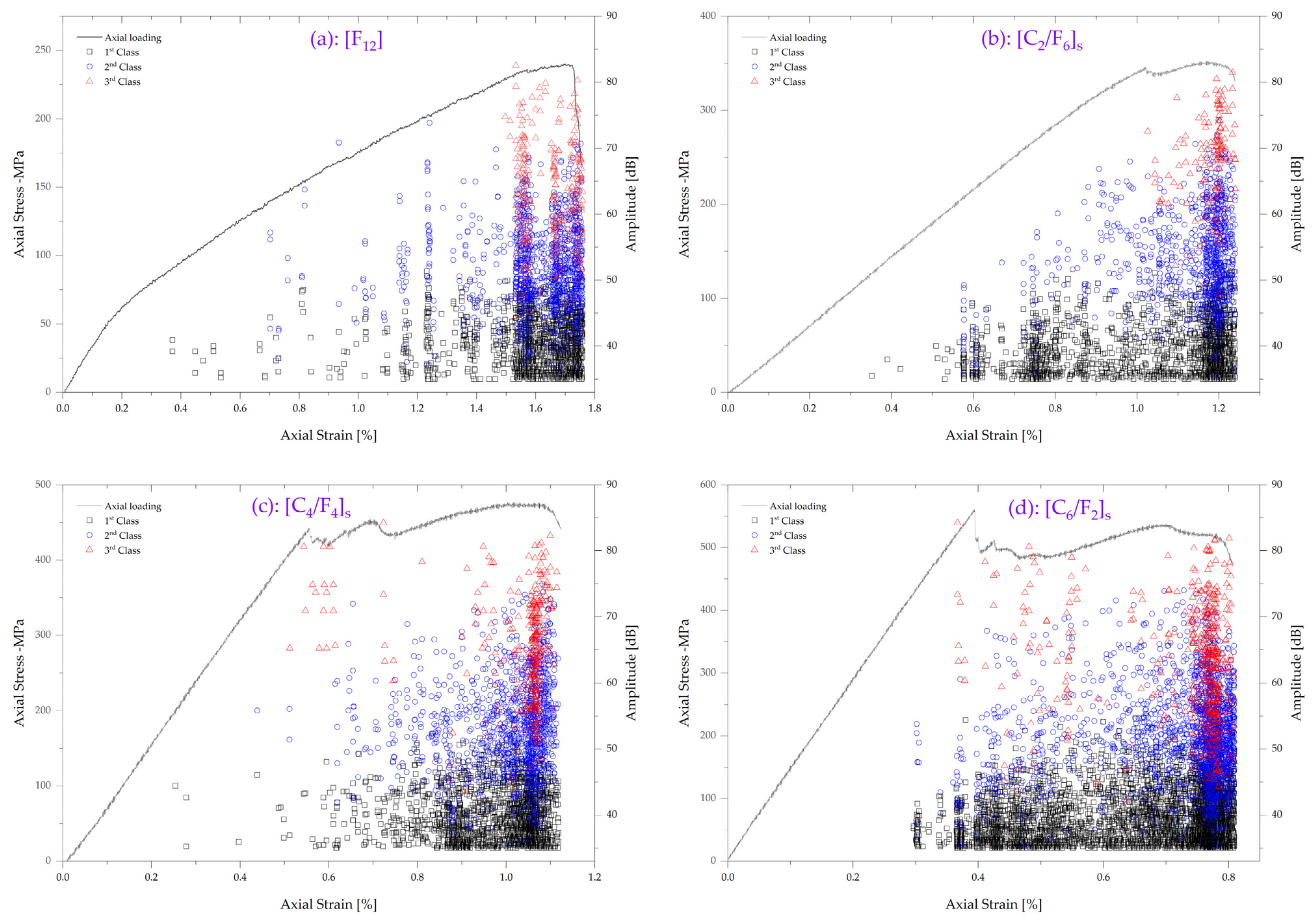
Based on previous results from tensile samples, the detected acoustic emission signals could be assigned to the occurrence of matrix cracking, interfacial failure, and fiber breakage. One representative classification result for one specimen of each composite is shown in
Figure 8.
With increased flexural load, acoustic emission signals must initiate at weak spots inside composites. Subsequently, the first class of acoustic emission signals is classified as matrix cracks, with an amplitude ranging between 35 dB and 55 dB. The second class of acoustic emission signals is classified as interfacial failure, with an amplitude ranging between 35 dB and 67 dB. Based on the fractured sample of
Figure 8, interfacial failure can be discussed in the following as a delamination failure mechanism. The third class of the AE signal is associated with fiber breakage, with an amplitude ranging between 45 dB and 85 dB.
4.3.2. Description of Damage Evolution in the Flexural Load of Composites
As seen in
Figure 8, the onset of acoustic emission signals appears at later load–strain stages. Generally, in three-point bending tests, the maximum shear force occurs at the neutral axis of the loaded specimen. The interlaminar crack grows and leads to damage in a material that causes acoustic activity onset. According to the flexural test standard, the first load drop at the ultimate strength represents the onset of damage in the material. In this case, the onset of damage is detected at a much lower load level, where the flexural test standard assumptions are not fulfilled. Accordingly, for both non-hybrid and hybrid tested composite, the onset of acoustic signals can be attributed to plastic deformation prior to interlaminar failure.
As revealed by
Figure 8, no significant amount of acoustic emission signals is detected before reaching around 90% of the ultimate flexural strain for flax composite (
Figure 8a) or before the first load drop for hybrid composites (
Figure 8a–c). A significant amount of acoustic emission signals associated with interfacial failure and fiber breakage are detected at this step. This suggests the onset of critical crack growth and, therefore, the beginnings of critical material damage. However, the significance of this intensification of acoustic emission activity and the effect of hybridization can be interpreted by the accumulated AE energy of the different signal clusters.
4.3.3. Contribution of Damage Mechanism in Flexural Failure
Further information on the contribution of different mechanisms in flexural failure can be obtained by investigating the development of the accumulated AE energy.
The load, accumulated AE energy versus strain curves for all damage mechanisms are shown in
Figure 9. Once again, evaluating the damage progression level or determining their contribution based on the released energy is often possible. Thus, the occurrence of different damage types and their evolution can be discussed, correlating to distinct and relevant load levels. A distinction can be made for all composite configurations for three significant stages of damage progression.
For flax composite ([F16]), even if some acoustic signals associated with matrix cracking and interfacial failure are detected, their accumulated energy is almost negligible. This indicates a state of damage initiation without a significant occurrence of microscopic damage. Interfacial failure clusters start to release considerable energy at around 55% of the ultimate flexural load, corresponding to a strain value of 0.7%. Interfacial failure gradually increases until reaching 90% of the ultimate flexural strain, where released energy by fiber breakage shows a sharp damage development. The relative contribution of matrix cracking is less than 1%. Despite the earlier onset and intensification, the average contribution of interfacial failure clusters is quantified at around 12%. A dominant effect of fiber breakage affects the structural integrity of the composite specimen.
Different behaviors are observed for hybrid composites. For the first hybridization level ([C2/F6]s), significant energy associated with interfacial failure is located at the same strain value as flax composite, of 0.7%. The major contribution to composite failure by fiber breakage did not take long to grow proportionally to interfacial failure. The load drop might result from fiber breakage or interfacial failure damage propagation. It is clear that hybridization balances the contribution of both damage mechanisms to reach an equivalent value of about 44%. However, the correlation of the load drop to interfacial failure or fiber breakage is hardly justified. This is because the composite failure is caused by a relative contribution of these two damage mechanisms.
As discussed in
Figure 3c,d, the increase in carbon fiber content produces a noticeable change in the induced damage. [C
4/F
4]
s samples show a kink band at the top carbon surface, where the first drop in the stress–strain curve was attributed to buckling. For the [C
6/F
2]
s composite, the increase in the hybridization rate shows a more pronounced development of buckling at the top carbon plies, as the position of the failure onset. The propagated shear-driven failure is transformed into delamination at the interface between the flax and carbon layers.
It was already important to determine whether the development of buckling at the top surface and propagation of the kink band can be correlated with the further stepwise drop at stress.
Figure 9c,d show that the evolution of accumulated energies agrees with interpreting the failure mechanisms observed in the fractured samples. Accumulated energy shows that fiber breakage happens systematically before the onset of interfacial failure. Additionally, it is essential to correlate the accumulated energy to the distribution of the acoustic signal in
Figure 8c,d.
After the first load drop and the significant contribution of fiber breakage, this damage mechanism stabilizes while the interfacial failure increases. This confirms that the failure starts from top carbon plies and develops as a shear-driven failure. After that, the propagated shear failure is transformed into delamination.
Finally, with increasing carbon fiber content, it is observed that the contributions of the fiber breakage mechanism dominate, where the damage contribution is increased from 66% to 80% for [C4/F4]s and [C6/F2]s composites, respectively. The contribution of interfacial failure tends to decrease from 32% to 20%, while the matrix cracking contribution is almost negligible.
5. Conclusions
This study presented new results on the experimental research of flax/carbon hybrid composite behaviors. Important findings include:
Hybridization of natural fibers with synthetic fibers such as flax and carbon brings a wide range of mechanical properties, starting from those of flax composites to the higher ones of carbon composites, that can better fit the specific requirements of different applications. This increases the flexibility of balancing the specific advantages of each fiber type, such as cost, density, environmental effect, etc.
The hybridization of flax with carbon highlighted the effect of the difference in the strain-to-failure between fibers. Tensile loading of the different hybrid composites confirmed the same fracture behavior. The lower strain-to-failure of carbon fibers was conducted to a typical catastrophic brittle fracture and delamination between layers. In the case of flexural loading, the strain difference showed an intensified effect of delamination.
AE-based damage-mechanism identification confirmed the previous observations. The classification of the acoustic events and the identification of damage mechanisms revealed that the failure of the hybrid composites dominated the contribution of interfacial damage and fiber breakage mechanisms, regardless of the loading type.
The quantitative analysis of the accumulated acoustic emission (AE) energy has provided valuable insights into the contribution and evolution of different damage mechanisms in the tensile and flexural failure of the hybrid composites. The results highlight the following key findings:
Tensile failure:
- –
Interfacial failure modes, fiber debonding, and delamination clusters exhibited significant contributions to the failure of the hybrid composites.
- –
The flax composite ([F16]) displayed a predominant occurrence of interfacial failure, with average contributions of approximately 45.4% for fiber debonding and 43.8% for delamination.
- –
Matrix cracking and fiber breakage also contributed to the failure, demonstrating comparable contributions of around 5% to 6%.
- –
The accumulation of AE energy revealed that delamination initiated earlier compared to other composites, while fiber breakage exhibited intense energy release at later strains, challenging the initial failure scenario assumption.
- –
The [C2/F6]s hybrid composites showed a notable sensitivity to delamination, particularly before reaching approximately 70% of the ultimate tensile loading.
- –
Matrix cracking and fiber debonding made minor contributions, with only 1% and 5% of the accumulated AE energy, respectively.
Flexural failure:
- –
Interfacial failure played a significant role in the flexural failure of the hybrid composites, similar to the behavior observed in the flax composite ([F16]).
- –
Fiber breakage exerted a dominant influence on the structural integrity of the composite specimens, while matrix cracking made negligible contributions.
- –
The load drop observed in the hybrid composites could be attributed to either fiber breakage or interfacial failure damage propagation, indicating a relative contribution of these two mechanisms.
- –
Hybridization balanced the contributions of interfacial failure and fiber breakage, resulting in an equivalent contribution of approximately 44%.
- –
Matrix cracking and fiber debonding exhibited minor contributions of around 1% and 9%, respectively.
Results of event classification showed a distinct number of clusters between tensile and flexural loading. The Davies–Bouldin index showed optimal clustering with four classes and three classes for each loading type, respectively. The difference is attributed to the distinction of interfacial damage events, particularly fiber pull-out from delamination, in the case of tensile loading. The method used did not allow the distinction of AE events related to flax or carbon fibers. Supervised classification methods should be used in future work to classify the AE events depending on the fiber type.
In conclusion, our study has shed light on the crucial role of the hybridization rate in the mechanical properties of our composite. However, it is worth noting that factors beyond hybridization, such as the stacking sequence, could significantly impact the composite’s mechanical behavior and failure modes. The influence of the stacking sequence, a parameter that was not the primary focus of our study, cannot be underestimated and deserves careful consideration. Variations in this parameter could potentially lead to divergent outcomes. As such, we suggest that future research in this area should contemplate the potential effects of different stacking sequences. This exploration could unlock further optimization possibilities for these composites, underlining the intricate nature and vast potential residing within the field of composite materials research.


