Abstract
This study investigates wind turbine structural dynamics using stochastic analysis and computational methods in both the time and frequency domains. Simulations and experiments are utilized to evaluate the dynamic response of a wind turbine structure to turbulent wind loads, with the aim of validating the results based on real wind farm conditions. Two approaches are employed to analyze the dynamic responses: the frequency domain modal analysis approach, which incorporates von Kármán spectra to represent the turbulent wind loads, and the time domain Monte Carlo simulation and Newmark methods, which generate wind loads and determine dynamic responses, respectively. The results indicate that, for a larger number of samples, both methods consistently yield simulated turbulent wind loads, dynamic responses and peak frequencies. These findings are further validated through experimental data. However, when dealing with a smaller number of samples, the time domain analysis produces distorted results, necessitating a larger number of samples to achieve accurate findings, while the frequency domain method maintains accuracy. Therefore, the accurate analysis of wind turbine structural dynamics can be achieved using simulations in both the time and frequency domains, considering the importance of the number of samples when choosing between time domain and frequency domain analyses. Taking these considerations into account allows for a more comprehensive and robust analysis, ultimately leading to more effective outcomes.
1. Introduction
The analysis of the dynamic response of wind turbine structures requires the use of computational methods in both the time and frequency domains, incorporating stochastic analysis. Wind speed fluctuates randomly in both time and space. Various sizes of eddies conveyed by the mean flow would represent this phenomenon, with different sizes of eddies representing this occurrence. Large eddies result in low-frequency fluctuations, while small eddies result in high-frequency ones. To describe the distribution of turbulence energy with frequency, a power spectral density function, or “power spectrum”, is typically used [1]. While there are different power spectrum representations of turbulent wind loads, the Kármán-type power spectrum is commonly used in structural codes, with the von Kármán spectrum considered to represent atmospheric turbulence more accurately [1]. Burton et al. [2] strengthened this concept, stating that the Kaimal and von Kármán spectra are the most frequently used expressions of the wind spectrum, with the von Kármán spectrum being the preferred choice.
In addition to the methods discussed earlier, the Monte Carlo simulation is another reliable tool for estimating turbulent wind loads in dynamic systems and remains widely used. Shinozuka and Jan [3] developed a digital simulation method of multivariate Gaussian random processes to represent a physical process in structural engineering. They also created a digital simulation of envelope functions using cosine functions with random phase angles, which was used as a tool for the Monte Carlo method of solution in various structural engineering applications [3,4]. Wittig and Sinha [5] demonstrated that using the summation of trigonometric functions with a Fast Fourier Transform (FFT) can improve computational efficiency.
The Newmark method is a widely used numerical integration algorithm for structural systems subjected to dynamic loads. It was originally developed for solving second-order differential equations in structural dynamics. The method approximates the displacement, velocity and acceleration at a future time using two parameters that can be chosen independently of each other [6]. It is important to carefully select these parameters, in addition to the time-step size, in order to achieve an accurate and stable integration scheme in the time domain. When the parameters are selected for an unconditionally stable scheme, the Newmark method is generally preferred for systems with a small number of modes that contain most of the significant parts of the solution [7].
On the other hand, the frequency response method, incorporating modal analysis, is commonly utilized in the dynamic analysis of structures, as described by Wirsching et al. [8] and Brandt [9]. Modal analysis characterizes the system’s dynamics independently of the applied loads and responses. By associating the modal response with the applied loads, the dynamic response of structures to these applied loads can be determined. This approach is particularly relevant for wind turbine structures, where modal characteristics play a crucial role in determining their dynamic responses [10].
Additionally, wind loads on wind turbine structures exhibit stochastic behavior and can be modeled as stationary processes, assuming a linear and time-invariant transfer between the loads and the responses of the system [11]. This modeling approach allows for the analysis of wind turbine structures under varying wind conditions, considering the stochastic nature of the loads.
Therefore, the dynamic response analysis of wind turbine structures can be performed using either the time domain method, the frequency domain method or a combination of both. Some studies preliminarily utilize the time domain method to represent different load conditions and dynamic responses, with a few results represented in the frequency domain [12,13,14,15,16,17]. Conversely, the frequency domain method is predominantly used to analyze the dynamic response of the structure to various load conditions [18], although both methods can also be implemented for load conditions and responses [19,20,21,22,23].
Given that both methods are frequently employed for the dynamic analysis of wind turbine structures, which are typically stochastic and require large numbers of samples of load and response data, assessing their comparative advantages would be beneficial in terms of achieving an effective analysis approach. By understanding the strengths and limitations of each method, researchers and engineers can make informed decisions regarding the most suitable approach for their specific analysis needs. This assessment would contribute to optimizing the analysis process and potentially reducing costs.
In this paper, the researchers focused on investigating the structural dynamics of wind turbines by analyzing their response to turbulent wind loads. To achieve this, they employed stochastic analysis and computational methods. Firstly, they simulated turbulent wind loads in the frequency domain using the von Kármán spectrum representation. This involved utilizing the Monte Carlo simulation and Inverse Fast Fourier Transform (IFFT) techniques. By doing so, they were able to obtain the corresponding time-domain turbulent wind load.
Next, the researchers implemented the Newmark method for time-domain dynamic response analysis. This method allows for the calculation of the structural response of the wind turbine under the influence of the turbulent wind load. Additionally, a modal analysis, along with the power spectrum of the turbulent wind load, was implemented for the dynamic response analysis in the frequency domain. Modal analysis helps in understanding the natural vibration modes of the wind turbine structure.
To validate their methods, the researchers compared the results obtained from their simulations with the measured dynamic response of a wind turbine at a specific wind farm. This comparison served as a means to verify the accuracy of their approaches. Based on their findings, the researchers discussed the comparative advantages of the two methods employed. They likely highlighted the strengths and limitations of each method and potentially identified areas where the methods performed best.
Overall, this paper aimed to provide insights into the dynamic behavior of wind turbine structures under turbulent wind loads. By utilizing stochastic analysis, computational techniques and validation against real-world measurements, the researchers contribute to the understanding and improvement in wind turbine design and analysis.
2. Materials and Methods
In order to investigate the dynamic response of wind turbine structures, a comprehensive approach with complex assessments of stochastic analysis and computational methods was employed. This involved conducting experiments and simulations to accurately assess the behavior of wind turbines. To achieve this, a model of random wind load that accurately represented the wind conditions experienced in an existing wind farm was created. Additionally, the wind turbine structure was modeled using design geometries and the mechanical properties of the materials used. To validate the results, strain gauge measurements of the wind turbine’s response were collected from the selected wind farm.
2.1. Modeling the Wind Turbine Structure
In order to investigate the dynamic response of wind turbine structures to turbulent wind loads at the hub, the simulation process incorporates the actual parameters of an existing wind turbine. This approach allows us to compare the simulation results with the measured data obtained from the same wind turbine on site. The analysis took into account various parameter values of the existing turbine, including the hub height (); the mass per unit length of the tower (); the tower-top mass (), which represents the combined mass of the nacelle and the blades; and the outer diameter of the tower () and inner diameter of the tower (), which are represented based on the average values. Furthermore, the modulus of elasticity (E), the cross-sectional area (A) and the moment of inertia (I) were determined based on the mechanical and geometrical values of the turbine.
To accurately model the wind turbine using the parameters mentioned earlier, it is essential to determine the most influential and dominant degree of freedom. This is achieved by analyzing the first three mode shapes of the tower system, as illustrated in Figure 1. By comparing the relative deflection values, it was observed that the first mode shape at the tip exhibits the highest deflection. In structural dynamics, the first natural frequency of a system is often considered a key indicator of its dynamic responses.
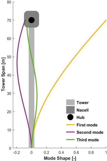
Figure 1.
Mode shapes of the wind turbine tower.
In the design of large wind turbine structures that utilize variable-speed generators, it is common practice to operate within the soft–stiff range. This implies that the first natural frequency of the structure should fall between the rotor frequency (1P) and blade-passing frequency (3P) for three-bladed wind turbines [24]. Based on this consideration, it is appropriate to represent the turbine structure using a single degree of freedom in this particular case.
To facilitate the dynamic analysis of the wind turbine structure, two modeling strategies were employed. The first approach involved representing the structure as an equivalent single-degree-of-freedom system, which offers a relatively simple representation. In this method, the inertial effect of the tower mass was accounted for by introducing an equivalent mass on the top of the structure. Additionally, the elasticity and damping effects of the tower structure were modeled using equivalent stiffness and damping values. This simplified modeling technique allows for a more manageable analysis of the dynamic behavior of the wind turbine structure.
Based on the equivalent mass calculation provided by Tom Irvine [25], the total mass of the wind turbine structure can be represented using the mass on top of the tower, the mass per unit length of the tower and the tower height as:
Next, the equivalent stiffness of the structure is represented by the equation:
To account for damping in the system, a general damping ratio of ζ = 0.2–0.5% is considered for such structures. The damping coefficient is then represented by:
where the natural frequency () is defined as:
Based on these calculations, the wind turbine structure is represented as a single-degree-of-freedom system, as depicted in Figure 2, along with its corresponding equivalent model.
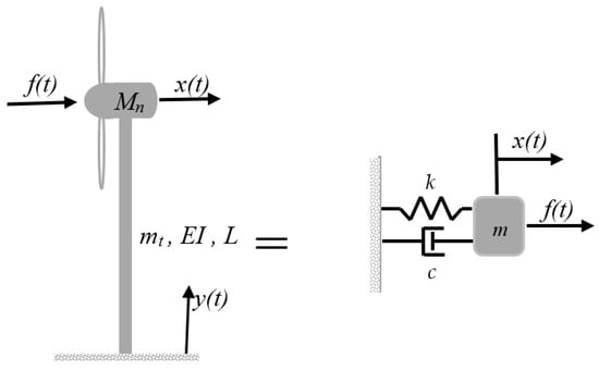
Figure 2.
Wind turbine tower structure with a corresponding equivalent model.
Based on this model, the equation of motion was defined as:
The second method of modeling involves modal methods with distributed parameters. In this approach, the system, including the tower with distributed mass, can be represented using Equations (7)–(10) to determine the modal mass, damping, stiffness and forces on the assumed mode shape defined in Equation (6). The equations are described in [26] and presented with some modifications as follows:
The modal mass, denoted as is calculated in terms of the distributed tower mass () and the assumed mode shape , as well as the contribution from individual mass () at specific locations in the length of the tower () as:
Similarly, the modal stiffness, denoted as , is determined in terms of the assumed mode shape , the bending stiffness , the distributed stiffness and the individual stiffness () at specific locations (). It is represented as:
The modal damping, denoted as , is then calculated in terms of the modal mass (, the damping ratio ( and the natural frequency () as:
To determine the excitation force in the modal equation of motion, the distributed force , the mode shape and the contributions from individual forces at specific locations are employed:
Finally, the modal equation of motion is modeled as:
This modal equation of motion allows us to analyze the dynamic behavior of the wind turbine structure in terms of modal quantities. To evaluate the transformed time response , time integration methods were employed with Equation (11). Ultimately, this provided the real-time response , as expressed in the following equation:
Both the modal method and the equivalent model technique provide simplified models that capture the fundamental parameters required for dynamic analysis. These models serve as a foundation for further analysis, where mathematical models for turbulent loads and dynamic responses are applied. By employing these methods, we can gain valuable insights into the behavior of the wind turbine structure under varying wind conditions, enabling us to assess its performance and make informed design decisions.
2.2. Frequency Domain Analysis
By applying the Laplace transform to the equations of motion stated in Equation (5) or Equation (11), and introducing a change in variable from time t (s) to frequency (rad/s), we can evaluate the transfer function in the frequency domain. After performing some algebraic manipulations, the transfer function was defined as follows:
In this equation, represents the natural frequency in Hz, and denotes the damping ratio of the structure.
At this point, either Equation (5) or Equation (11) can be used to analyze the dynamic response using the time and frequency domain methods, with the input force being a turbulent wind load in the wind direction represented by , which was modeled as:
The variables used are: ρ: air density; thrust coefficient; swept area of the blades; overall wind velocity; mean wind velocity; and turbulent wind velocity. Expanding the equation, we obtain:
Assuming that the impact of higher power components ( will be insignificant when compared to other components, Equation (15) can be rearranged to express as:
This equation represents the combined wind load resulting from both the mean wind velocity and the turbulent component. However, it is possible to solely consider the dynamic part, which specifically corresponds to the turbulent wind load. The inclusion of the mean wind load can be addressed at later stages, if deemed necessary. The expression for the turbulent wind load was formulated as follows:
This turbulent wind load has a zero mean value. To calculate the autocorrelation of the dynamic wind load, we use the expected value of Equation (17), represented as:
Simplifying Equation (18), the autocorrelation of the dynamic wind load can be expressed as:
The power spectral density of the dynamic wind load was determined using the autocorrelation of the turbulent wind load (Equation (19)) and defined as:
The power spectral density of the dynamic response of the structure was determined by combining the transfer function and power spectrum of the turbulent wind load as:
Finally, the turbulent wind power spectral density was determined based on the von Kármán spectra [1,2] as:
where , in which is the integral length scale of the turbulent wind load; is the frequency in Hz, which can be replaced by in rad/s; and is the variance or standard deviation of the turbulent wind load, which is related to the turbulent intensity and mean wind speed as:
The turbulent wind load parameters used to analyze the dynamic response of the structure were determined based on the specific wind farm conditions being considered. To comply with the IEC 61400-1 standard [27], the turbulent intensity value was evaluated using the equation , where for sites with high turbulence intensity and a wind velocity of . The reference wind velocity ( in this case was determined to be 42.5 m/s for wind class II. Additionally, the variance was computed using Equation (23), and all other relevant variables were determined in accordance with the established standard and the actual wind farm conditions.
2.3. Time Domain Analysis
A Monte Carlo simulation using cosine functions with random phase angles was used to determine an equivalent turbulent wind load in the time domain. This involved representing the load as the sum of cosine functions with random phase angles. The resulting equation for the turbulent wind load in the time domain is:
In this equation,, where and . The period can be expressed in terms of the number of samples and the change in time as . The number of samples represents the length of the data being used. In this case, has been set to 0.01 to demonstrate different results for a varying number of samples, as shown in Section 3.
In addition to the aforementioned method, the turbulent wind load in the time domain can also be evaluated using the Inverse Fast Fourier Transform (IFFT) of the power spectral density (PSD). This technique can be implemented using the IFFT functions in software programs like Matlab or other coding platforms as:
Then, the Newmark method, coupled with the turbulent wind load in the time domain and the system parameters from Section 2.1, was employed to evaluate the time response by integrating Equation (5) or Equation (11) following Mendes et al.’s algorithm [28] as follows:
- o
- Provide initial values for displacement, velocity and external force:
- o
- Solve for the acceleration:
- o
- Define an integration step Δt constant in the iterative process.
- o
- Determine an effective stiffness matrix :
- o
- Determine auxiliary matrices and :
- o
- Then proceed to an iterative process as follows:
- a.
- Solve the equation of dynamic equilibrium for the calculation of as:
- b.
- Determine displacement, velocity and acceleration variations as:
- c.
- Update the variables :
To insure stability in the Newmark method, the condition is when , with ωmax being the maximum un-damped natural frequency of the structure. The method is unconditionally stable for , and in this case, the acceleration term in the above iterative process is assumed to be a constant average value during the time interval .
2.4. Evaluation and Validation Processes
By formulating the necessary relationships and parameters, a Matlab code was utilized to conduct dynamic response analysis in both the frequency and time domains. In the frequency domain analysis, turbulent wind loads were generated using von Kármán spectra, taking into account the specific site conditions. To capture the dynamics of the structure, a governing mathematical model was applied, incorporating the turbine’s structural parameters under selected field conditions. By combining modal analysis with the power spectrum of the turbulent wind load, the structure’s dynamic responses in the frequency domain were determined.
For the time domain analysis, a Monte Carlo simulation technique was employed, utilizing the von Kármán spectrum of the turbulent wind loads to generate simulated frequency domain input forces. From these simulated forces, equivalent time domain input forces were obtained. The Newmark method, employing unconditional stability parameters, was then employed to determine the dynamic response in the time domain. The obtained results were subsequently transformed back into the frequency domain using the Fast Fourier Transform (FFT) technique and compared against the results obtained from the direct frequency domain analysis. This allowed for a fair and comprehensive comparison between the two domains.
Consequently, various frequency domain parameters of the wind turbine structure, as well as the turbulent wind loads and associated dynamic responses such as peak frequencies and the root mean squared (RMS) values of the response amplitudes, were evaluated and prepared for comparison. To validate the accuracy of the simulations, existing data on the dynamic response of the structure, measured using strain gauges positioned approximately 4 m above the ground, were considered. These measured data were used to determine the peak frequencies for the dynamic response of existing wind turbines, as showcased in both response plots from the time and frequency domains. Since the simulation parameters were tailored to the same turbine, the frequency responses obtained from the simulations were validated against the measured data for further accuracy assessment.
3. Results and Discussion
The turbulent wind loads in the time domain were evaluated using a Matlab code with the Monte Carlo simulation technique and the IFFT technique as outlined in Section 2.3 with Equations (24) and (25). The analysis revealed that the root mean squared values of the amplitude for both results and the PSD of the turbulent wind load using von Kármán spectra were found to be equal. Furthermore, Figure 3 demonstrates that the results obtained from the time domain simulations are identical. However, it is important to note that the Monte Carlo simulation method was found to be more time-consuming compared to the IFFT method. This finding is consistent with previous studies and becomes more pronounced when using a larger number of samples.
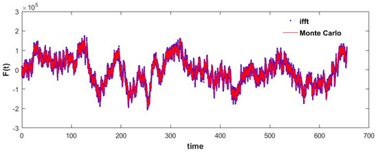
Figure 3.
Turbulent wind load using Monte Carlo Simulation and IFFT methods.
Therefore, in the subsequent steps, the IFFT method was employed to evaluate the turbulent wind loads in the time domain. Consequently, Figure 4a illustrates the power spectral density of the turbulent wind load obtained as a function of frequency ω, without any form of normalization. Additionally, Figure 4b demonstrates the same power spectral density in a normally distributed form, according to Equation (22). Figure 5 further displays the corresponding representation of the turbulent wind load in the time domain, which exhibits a mean value of zero. Notably, we observed that the RMS values of the power spectrum of the turbulent wind load align with those of its time domain representation.
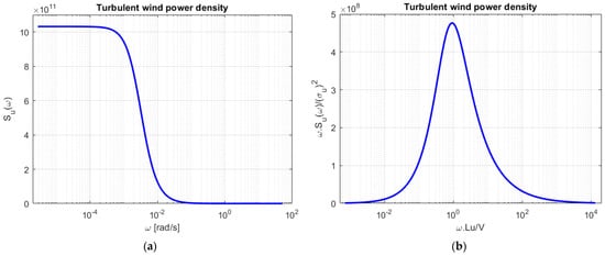
Figure 4.
Simulated turbulent wind load: (a) without normalization; (b) in normal distribution form.

Figure 5.
Simulated turbulent wind load in the time domain.
Then, using the time domain loads shown in Figure 5 as input forces to the structural system, the dynamic response of the structure was evaluated using the Newmark method. The resulting displacement response of the structure in the time domain is shown in Figure 6. This response was then transformed to the frequency domain to obtain the corresponding value in the frequency domain to verify the natural frequencies of the wind turbine structure.

Figure 6.
Displacement time response of the structure to turbulent wind load.
To validate the simulated results, recorded data of the dynamic response of an existing wind turbine, measured using strain gauges, data loggers and associated accessories at a height of approximately 4 m above the ground, were considered. The recorded data consist of 540 sample points recorded at approximately 0.5 s time intervals. Figure 7a shows the recorded data versus time for a real turbine plotted at mean zero. Then, the FFT was applied to obtain the power spectral density of the data and represent the frequency response as shown in Figure 7b. The spectrum shows a broader peak at lower, near-zero frequencies, consistent with the turbulent wind load and response spectrum, with a peak frequency of about 2.47 rad/s as the first natural frequency of the structure. Considering the time domain data, the peak frequency was determined to be approximately 2.45 rad/s. This slight difference is likely related to the size of the time interval, which is related to the sampling frequency used by the data recorder and the number of samples considered.
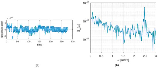
Figure 7.
Measured response data from a turbine on site: (a) time response; (b) power spectrum of response.
Meanwhile, the frequency response results of the simulations are illustrated in Figure 8. Specifically, Figure 8a displays the simulation result of the Newmark time response in the transformed frequency domain, while Figure 8b shows the result obtained through the direct frequency response method. Both figures present the power spectral density of the turbulent wind load and the structure, exhibiting similar characteristics. It is worth noting that, while the dynamic wind load’s peak frequency is observed at low frequencies close to zero, the natural frequency of the structure is approximately 2.45 rad/s in both cases. These findings align with the results obtained from the measured data, as presented in Figure 7.
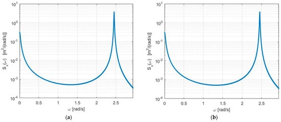
Figure 8.
Response PSD for a large number of samples: (a) using time response; (b) using direct frequency method.
In addition to the frequency peak points, Figure 8a,b demonstrate identical RMS values of the power spectrum for the dynamic response amplitudes. Furthermore, these RMS values are consistent with the RMS values of the response observed in the time domains. It is important to note that these results were obtained using a large number of samples (N of 224) for the turbulent wind load. To further investigate the effects of the number of samples used, we analyzed the results considering a smaller value of 218 for both cases, as shown in Figure 9. In this scenario, the time domain response using the Newmark method begins to exhibit scattering effects, as depicted in Figure 9a; conversely, the result obtained through the direct frequency method in Figure 9b remains nearly unchanged and displays a precise peak frequency value, similar to the previous result. Additionally, it is worth noting that the RMS value for the time domain response starts to deviate when compared to the results obtained using a larger number of samples. However, the frequency domain method demonstrates consistent outcomes with minimal variation, highlighting its reliability. To gain further insights, we conducted additional analyses by reducing the number of samples even further to 214. Figure 10a,b present the corresponding results in the same order. Notably, the time domain approach yields highly distorted results, indicating a significant loss of accuracy. In contrast, the direct frequency response method maintains its precision, showcasing the consistent peak frequency values and RMS values of the amplitudes.
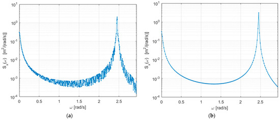
Figure 9.
Response PSD for smaller samples: (a) using time response; (b) using direct frequency method.
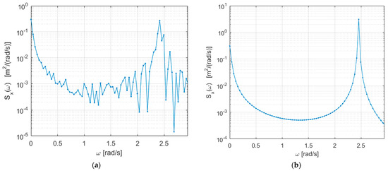
Figure 10.
Response PSD for further reduced samples: (a) using time response; (b) using direct frequency method.
Therefore, for a smaller number of samples, the time domain analysis may yield misleading results, necessitating larger samples to achieve accurate findings. However, this approach is computationally time-consuming compared to its counterpart. Conversely, the frequency domain analysis provides precise results with a smaller number of samples and is computationally less demanding. Time domain results can be effectively obtained utilizing direct frequency domain methods with the help of the IFFT technique. This allows for improved efficiency and accuracy in obtaining the desired time domain information.
4. Conclusions
In general, the investigation of the dynamic response of a wind turbine structure to turbulent wind loads was conducted in both the time and frequency domains. Stochastic analysis and computational methods were employed for this analysis. In the frequency domain analysis, von Kármán spectra were employed to generate turbulent wind loads. The dynamic response of the structure was analyzed using modal analysis combined with the power spectral density of the turbulent wind load. For the time domain analysis, the Monte Carlo simulation technique was utilized to simulate the input force, and the Newmark method was then applied to determine the dynamic response in the time domain.
To enable comprehensive comparisons between the two domains, the obtained time domain data were transformed to the frequency domain using the Fast Fourier Transform technique. A comparison was then made in the frequency domain. The accuracy of the analysis was validated using measured data for the dynamic response of the wind turbine structure. As a result, an almost perfect match between the peak frequencies of the dynamic wind load and the natural frequencies of the measured and simulated structures was achieved by utilizing a larger number of samples.
With a larger number of samples, both the time domain and direct frequency domain methods showed almost identical response results in terms of peak frequency values, root mean squared (RMS) amplitudes of the simulated input wind loads and dynamic responses of the structure. However, when using a smaller number of samples, the time domain analysis with the Newmark method deviated from these results, while the direct frequency domain method remained close to the measured data in terms of the frequency-related contents and RMS values of the amplitudes.
In conclusion, it is important to consider the number of samples when choosing between time domain and frequency domain analysis. For a smaller number of samples, the time domain analysis may produce misleading results and require larger samples for accuracy. However, frequency domain analysis offers precise results with smaller samples and is computationally less demanding. Additionally, time domain results can be effectively obtained utilizing direct frequency domain methods with the help of the inverse Fast Fourier Transform technique. Therefore, by comprehending the advantages and limitations of each approach, researchers can make informed decisions and analyze their systems effectively, leading to more accurate and reliable results.
Author Contributions
Conceptualization, H.K.K. and T.K.N.; Methodology, H.K.K.; Software, H.K.K.; Validation, H.K.K.; Formal analysis, H.K.K.; Investigation, H.K.K.; Resources, H.K.K., M.B.K. and T.K.N.; Data curation, H.K.K.; Writing—original draft, H.K.K.; Writing—review and editing, H.K.K., M.B.K. and T.K.N.; Visualization, H.K.K.; Supervision, T.K.N. and M.B.K.; Project administration, M.B.K.; Funding acquisition, M.B.K. and T.K.N. All authors have read and agreed to the published version of the manuscript.
Funding
This research received no external funding.
Data Availability Statement
Not applicable.
Acknowledgments
The authors would like to acknowledge the Capacity 5 project, a collaborative project between NTNU and EiT-M of Mekelle University, under the EnPe program of the Norwegian Government, for all kinds of support provided.
Conflicts of Interest
The authors declare no conflict of interests.
References
- Tamura, Y.; Kareem, A. Advanced Structural Wind Engineering; Springer: Tokyo, Japan, 2013. [Google Scholar]
- Burton, T.; Jenkins, N.; Sharpe, D.; Bossanyi, E. Wind Energy Handbook; John Wiley and Sons Ltd.: Chichester, UK, 2011. [Google Scholar]
- Shinozuka, M.; Jan, C.M. Digital simulation of random processes and its applications. J. Sound Vib. 1972, 25, 111–128. [Google Scholar] [CrossRef]
- Shinozuka, M. Monte Carlo solution of structural dynamics. Comput. Struct. 1972, 2, 855–874. [Google Scholar] [CrossRef]
- Wittig, L.E.; Sinha, A.K. Simulation of multi-correlated random processes using the FFT algorithm. J. Acoust. Soc. A 1975, 58, 630–634. [Google Scholar] [CrossRef]
- Newmark, N.M. A Method of computation for structural dynamics. ASCE J. Eng. Mech. Div. 1959, 85, 67–94. [Google Scholar] [CrossRef]
- Mirza, M.; Irfan, B.; Thomas, G. Recommendations for Practical Use of Numerical Methods in Linear and Nonlinear Dynamics; Hamburg University of Applied Sciences: Hamburg, Germany, 2021; Available online: https://www.coursehero.com/ (accessed on 22 April 2020).
- Wirsching, P.H.; Paez, T.L.; Keith, O. Random Vibrations Theory and Practice; John Wiley and Sons: New York, NY, USA, 1995. [Google Scholar]
- Anders, B. Noise and Vibration Analysis; John Wiley and Sons Ltd.: Hoboken, NJ, USA, 2011. [Google Scholar]
- Avitabile, P. Tutorial Notes: Structural Dynamics and Experimental Modal Analysis; University of Massachusetts: Lowell, MA, USA, 2000. [Google Scholar]
- Naess, A.; Moan, T. Stochastic Dynamics of Marine Structures; Cambridge University Press: Cambridge, UK, 2013. [Google Scholar]
- Barooni, M.; Ali, N.A.; Ashuri, T. An open-source comprehensive numerical model for dynamic response and loads analysis of floating offshore wind turbines. Energy 2018, 154, 442–454. [Google Scholar] [CrossRef]
- Cheng, X.; Wang, T.; Zhang, J.; Wang, P.; Tu, W.; Li, W. Dynamic response analysis of monopile offshore wind turbines to seismic and environmental loading considering the stiffness degradation of clay. Comput. Geotech. 2023, 155, 105210. [Google Scholar] [CrossRef]
- Bachynski, E.; Thys, M.; Delhaye, V. Dynamic response of a monopile wind turbine in waves: Experimental uncertainty analysis for validation of numerical tools. Appl. Ocean Res. 2019, 89, 96–114. [Google Scholar] [CrossRef]
- Xi, R.; Xu, C.; Du, X.; El Naggar, M.H.; Wang, P.; Liu, L.; Zhai, E. Framework for dynamic response analysis of monopile supported offshore wind turbine excited by combined wind-wave-earthquake loading. Ocean Eng. 2022, 247, 110743. [Google Scholar] [CrossRef]
- Sharma, T.; Choudhury, S.; Murari, V.; Shukla, K.K. The effect of shear web on the dynamic response of a wind turbine blade subjected to actual dynamic load. J. Mater. Des. Appl. 2021, 235, 1868–1878. [Google Scholar] [CrossRef]
- Tu, W.; He, Y.; Liu, L.; Liu, Z.; Zhang, X.; Ke, W. Time Domain Nonlinear Dynamic Response Analysis of Offshore Wind Turbines on Gravity Base Foundation under Wind and Wave Loads. J. Mar. Sci. Eng. 2022, 10, 1628. [Google Scholar] [CrossRef]
- Russo, S.; Contestabile, P.; Bardazzi, A.; Leone, E.; Iglesias, G.; Tomasicchio, G.R.; Vicinanza, D. Dynamic Loads and Response of a Spar BuoyWind Turbine with Pitch-Controlled Rotating Blades: An Experimental Study. Energies 2021, 14, 3598. [Google Scholar] [CrossRef]
- Kim, J.; Heo, S.; Koo, W. Analysis of Dynamic Response Characteristics for 5 MW Jacket-type Fixed Offshore Wind Turbine. J. Ocean. Eng. Technol. 2021, 35, 347–359. [Google Scholar] [CrossRef]
- Guo, S.; Li, Y.; Chen, W. Analysis on dynamic interaction between flexible bodies of large-sized wind turbine and its response to random wind loads. Renew. Energy 2021, 163, e123–e137. [Google Scholar] [CrossRef]
- Wang, S.; Huang, Y.; Li, L.; Liu, C.; Zhang, D. Dynamic analysis of wind turbines including nacelle–tower–foundation interaction for condition of incomplete structural parameters. Adv. Mech. Eng. 2017, 9, 1687814017692940. [Google Scholar] [CrossRef]
- Xie, S.Y.; Zhang, C.L.; He, J.; Jiang, J.; Gao, J. Dynamic response analysis and vibration control for a fixed-bottom offshore wind turbine subjected to multiple external excitations. China Ocean Eng. 2022, 36, 50–64. [Google Scholar] [CrossRef]
- Zhang, R.; Tang, Y.; Hu, J.; Ruan, S.; Chen, C. Dynamic response in frequency and time domains of a floating foundation for offshore wind turbines. Ocean Eng. 2013, 60, 115–123. [Google Scholar] [CrossRef]
- Tempel, D.-P.; Molenaar, D.-P. Wind turbine structural dynamics- A review of the principles for modern power generation, onshore and offshore. Wind. Eng. 2002, 26, 211–220. [Google Scholar] [CrossRef]
- Bending Frequencies of Beams, Rods, and Pipes. Available online: http://www.vibrationdata.com (accessed on 3 June 2023).
- Paz, M.; Kim, Y.H. Structural Dynamics: Theory and Computation, 6th ed.; Springer: Chama, Switzerland, 2019. [Google Scholar]
- IEC 61400-1, 2005-08; Wind Turbines Part 1: Design Requirements. International Electro-Technical Commission: Geneva, Belgium, 2005.
- Mendes, P.T.; Rodrigues, J.A.; Mendes, P. A Numerical Solution for Structural Vibration Problems; SYMCOMP: Lisbon, Portugal, 2013. [Google Scholar]
Disclaimer/Publisher’s Note: The statements, opinions and data contained in all publications are solely those of the individual author(s) and contributor(s) and not of MDPI and/or the editor(s). MDPI and/or the editor(s) disclaim responsibility for any injury to people or property resulting from any ideas, methods, instructions or products referred to in the content. |
© 2023 by the authors. Licensee MDPI, Basel, Switzerland. This article is an open access article distributed under the terms and conditions of the Creative Commons Attribution (CC BY) license (https://creativecommons.org/licenses/by/4.0/).