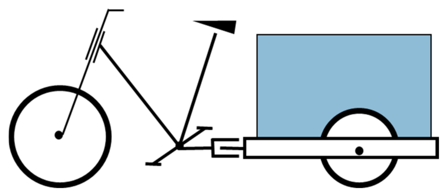
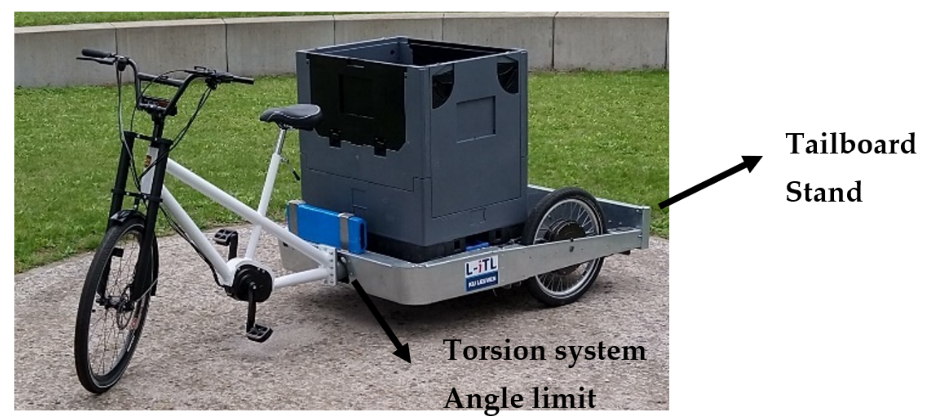
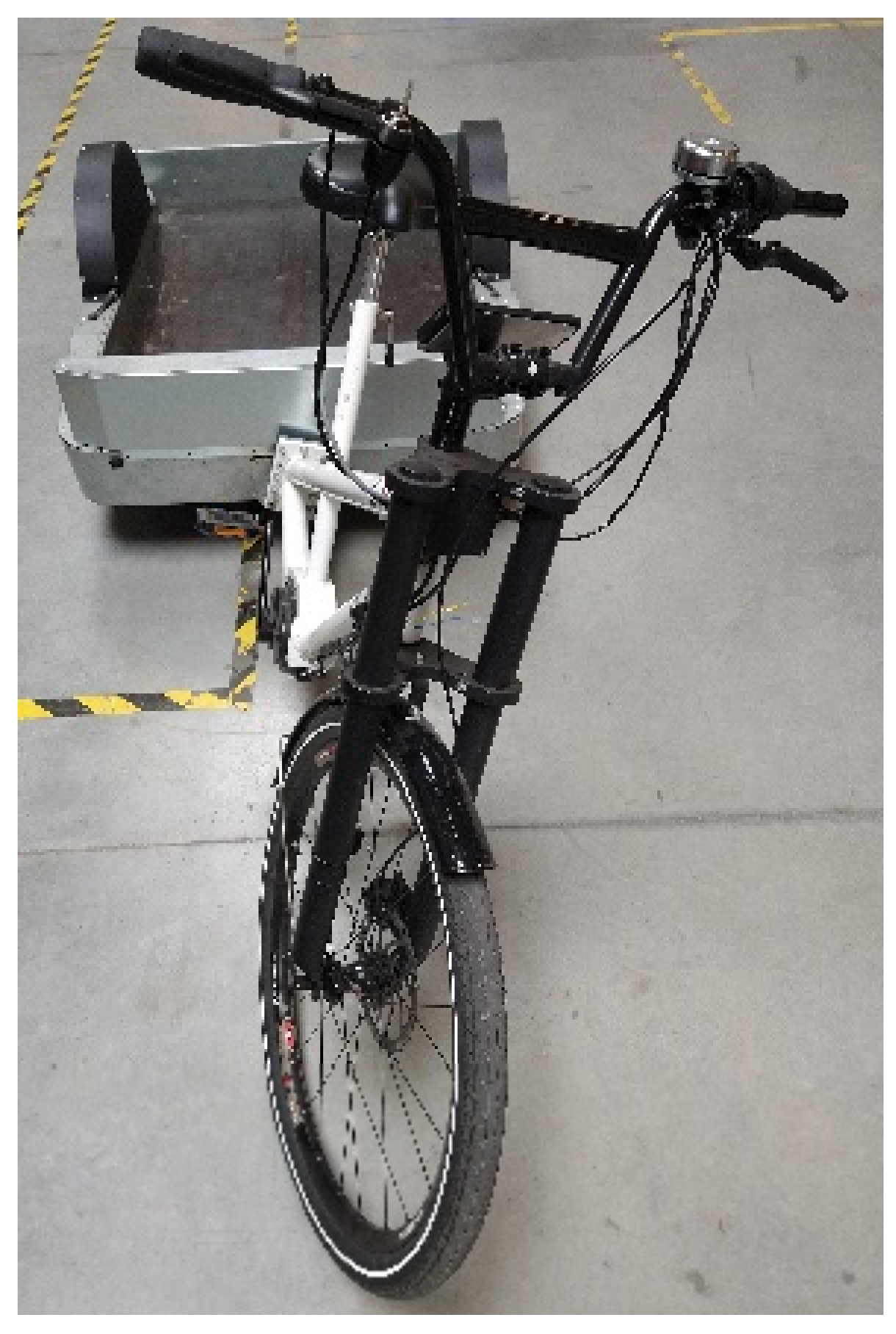
The concept vehicle has a tailboard on the back of the cargo module. The tailboard can rotate downwards and support the cargo module. This prevents the vehicle from tipping and raising the front wheel when loading and unloading a container. The incorporation of a torque system and angle limit in the hinge ensures a simple implementation in the concept vehicle. This system is chosen because it will prevent the driver module from falling over without the need to enable a locking mechanism. Furthermore, the torsion system can also aid in low-speed stability whilst having little to no influence on the manoeuvrability of the vehicle.
Effects of Torsion System on Stationary Stability
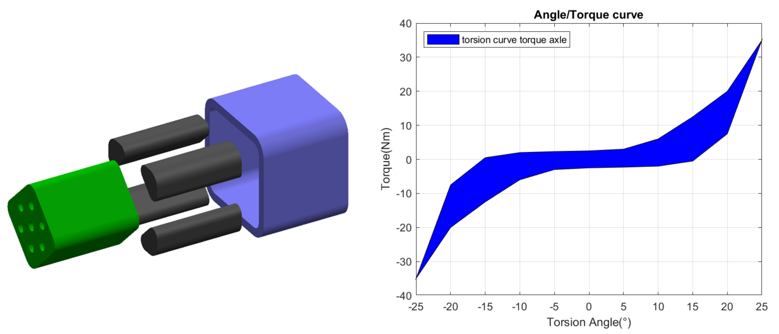
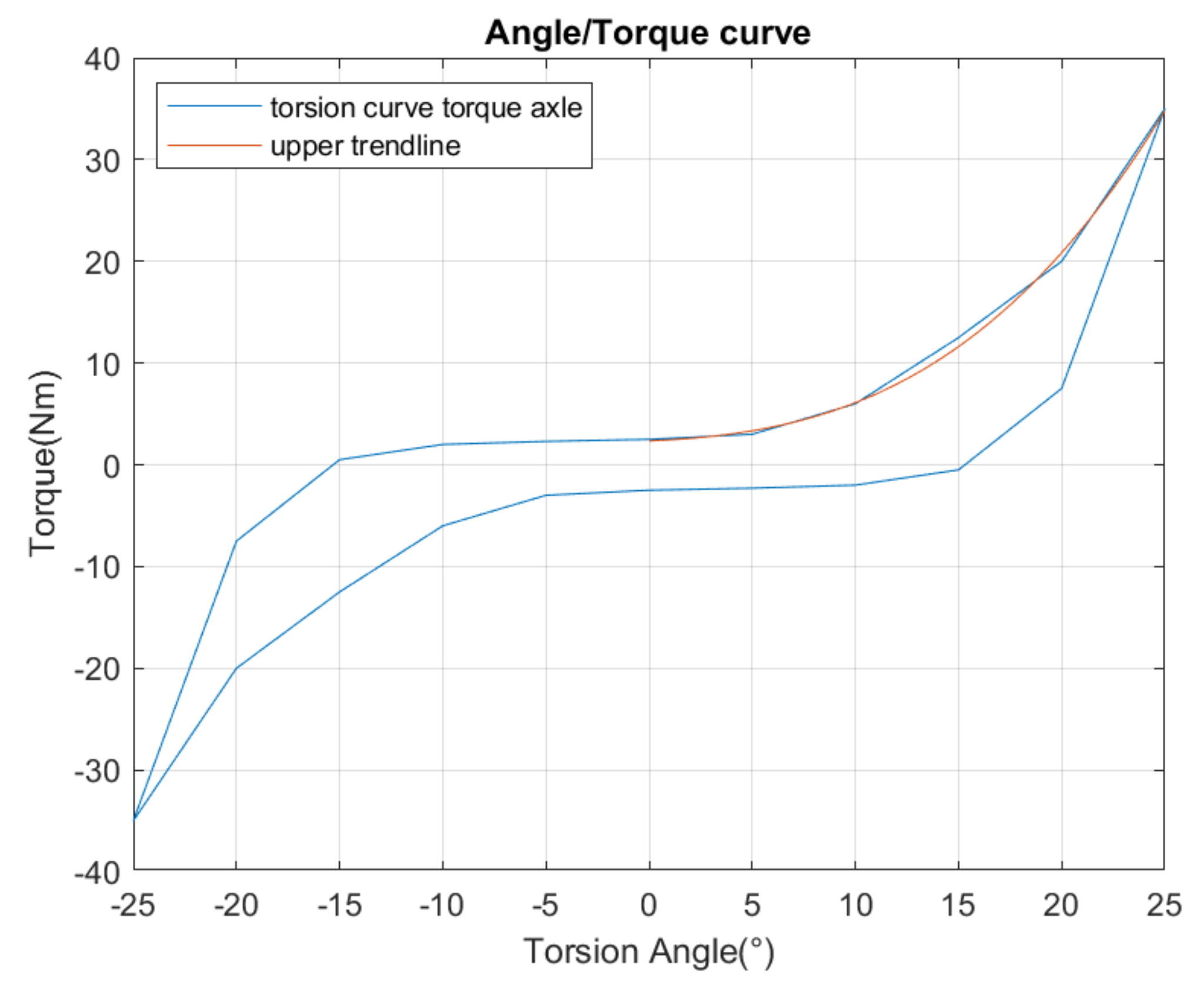
The concept vehicle is equipped with a torsion system that creates counter-torque when tilting. This provides an incorporated soft angle stop which limits the tilting and in extreme cases, an angle limit of 30° is used. A flexible torsion system was implemented in the concept vehicle as high-speed manoeuvrability has priority over low-speed stability. To acquire its torque/angle curve a torque is applied in an upward and downward motion and the angular deflection is measured. The graph, as seen in
Figure 5, is obtained. A third-degree polynomic trendline is fitted on the upper side for further calculations.
The elastomer torsion system has a typical hysteresis which provides a dampening effect. This reduces vibrations while cycling. The currently equipped torsion system has a zone between −5° and +5° where the torsion system creates almost no counter-torque. This small counter-torque is still enough to keep the driver module upright without a driver. However, when disturbed or while handling cargo, the driver module tilts between 14° and 17°.
This is measured after creating disturbances by loading and unloading the cargo hold. When the driver module is pushed to the angle limit, the driver module tilts back to a maximum of 22° as shown in
Figure 6. Tilting 22° accounts to the steer extending about 30 cm outside the width of the vehicle.
The torque the driver module applies on the hinge is calculated using Equation (1).
The centre of gravity distance is measured perpendicular to the hinge’s axis. While parked, the driver module is unmanned and has a mass of 15 kg and a centre of gravity distance of 0.3 m perpendicular to the hinge’s axis. While cycling the driver module is manned and has a mass of 90 kg and as centre of gravity distance of 0.8 m.
Equation (1) is however a simplification since there are multiple unknown variables. The steer can rotate which moves the point of support and creates an asymmetry in the centre of gravity. This has a bigger effect when the driver module is upright. When the driver module is tilted, the change is not that great. The steer is even pushed straight thanks to the geometry of the vehicle. Due to the uncertainty of the steer rotation and the small effect it has, this is neglected.
Furthermore, the weight distribution of the cargo module can create an additional force on the driver module. When the centre of gravity of the cargo module is inclining forward, the front wheel receives additional weight. This can create an additional torque in the hinge. In this concept, this has a limited effect due to the axis of the hinge intersecting with the contact point of the front wheel when positioned upwards.
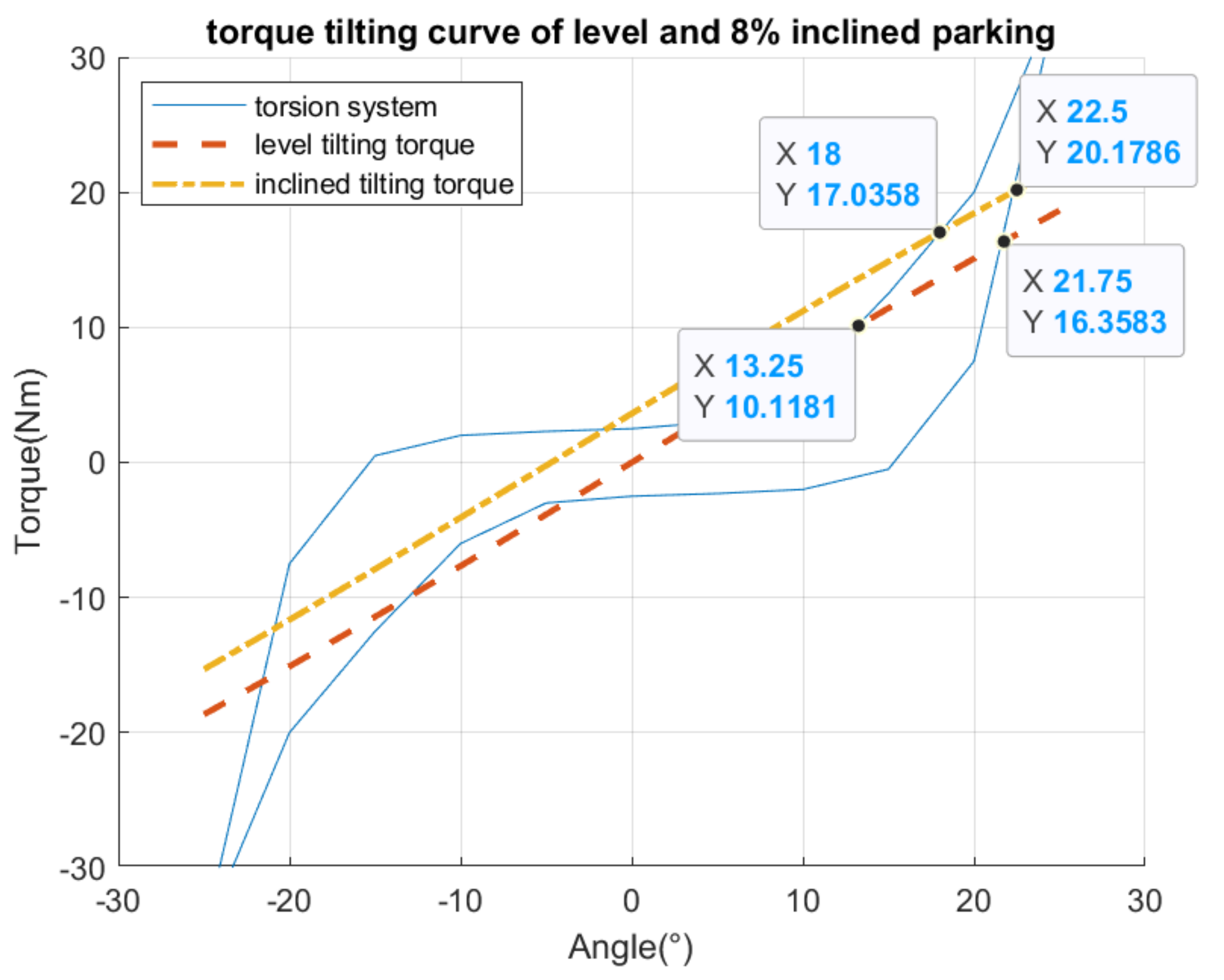
The calculated moment created by tilting on a level surface intersects with the counter-torque at 13.25° as shown in
Figure 7. When the vehicle is at a diagonal inclination of 8%, the driver module hinges between 18.5° and 22. 5°, resulting in a vertical inclination of 23.1° and 27.1°.
These calculations correspond to the measured values. Although the driver module stops tilting before the angle limit is reached, the driver module still tilts a decent amount which creates a tedious action when getting on the bike. Furthermore, the steer can extend 30 cm outside the vehicle’s width and fall onto close by vehicles. Increasing the counter-torque in the hinge will reduce this.
The torsion system has an influence while cycling. During manoeuvres, the driver tilts while cornering. Cornering causes the driver to lean inwards to compensate for the centripetal force. Cornering the vehicle at a certain radius at a certain velocity causes a centrifugal force as calculated in Equation (2).
This centripetal force acts on the driver module and the driver pushes it outwards of the turn. Tilting inwards counteracts this thanks to gravity as seen in Equation (1). This creates a total torque in the hinge stated in Equation (3).
Without a torsion system
is 0 Nm. When calculating it with the torsion system,
is substituted by the torque/angle curve. This results in a decrease in tilting due to the counter torque. Equation (3) is compared with measurements performed on the concept vehicle. Using measurements of different manoeuvres corresponding tilting angles are gathered according to the turning radius and the velocity. Multiple manoeuvres are performed with the vehicle and turns are sorted according to turning radius and velocity.
Figure 8 shows the measured tilting angle according to the turning radius. The colour is plotted according to velocity.
The measured and calculated tilting angles have a mean difference of 2°. Those differences can be explained due to simplifications in the equation. The driver who accounts for the majority of the driver module’s mass is considered rigid while this is not the case. During manoeuvres, the driver can rotate its torso, changing the centre of gravity. Taking a turn is never performed at a constant turning radius and velocity. Selected measurements are steady turns with a limited variation. The mean values during the turn are used for the calculations. The calculations are a simplification where the movement of the wheelbase due to steering and tilting is not taken into account as well as a slightly smaller turning radius of the driver module compared with the cargo module which is used to calculate the turning radius. The measurements are generated from manoeuvring tests which are conducted on pavement. However, the pavement is not completely flat, causing the cargo module to be slightly unlevel at times and influencing the measurement. The hysteresis present is also not taken into account.
Thanks to ability to tilt, the driver only experiences a fraction of the lateral acceleration compared to a fixed frame vehicle. While testing the maximum possible velocity driving a circle with a radius of 4 m the driver only experienced a lateral acceleration of 0.89 m/s
2 while a fixed vehicle experienced 4.5 m/s
2 [
9]. The driver experiences less lateral acceleration with the concept vehicle. A comfortable lateral acceleration is stated to be below 0.9 m/s
2 [
15].
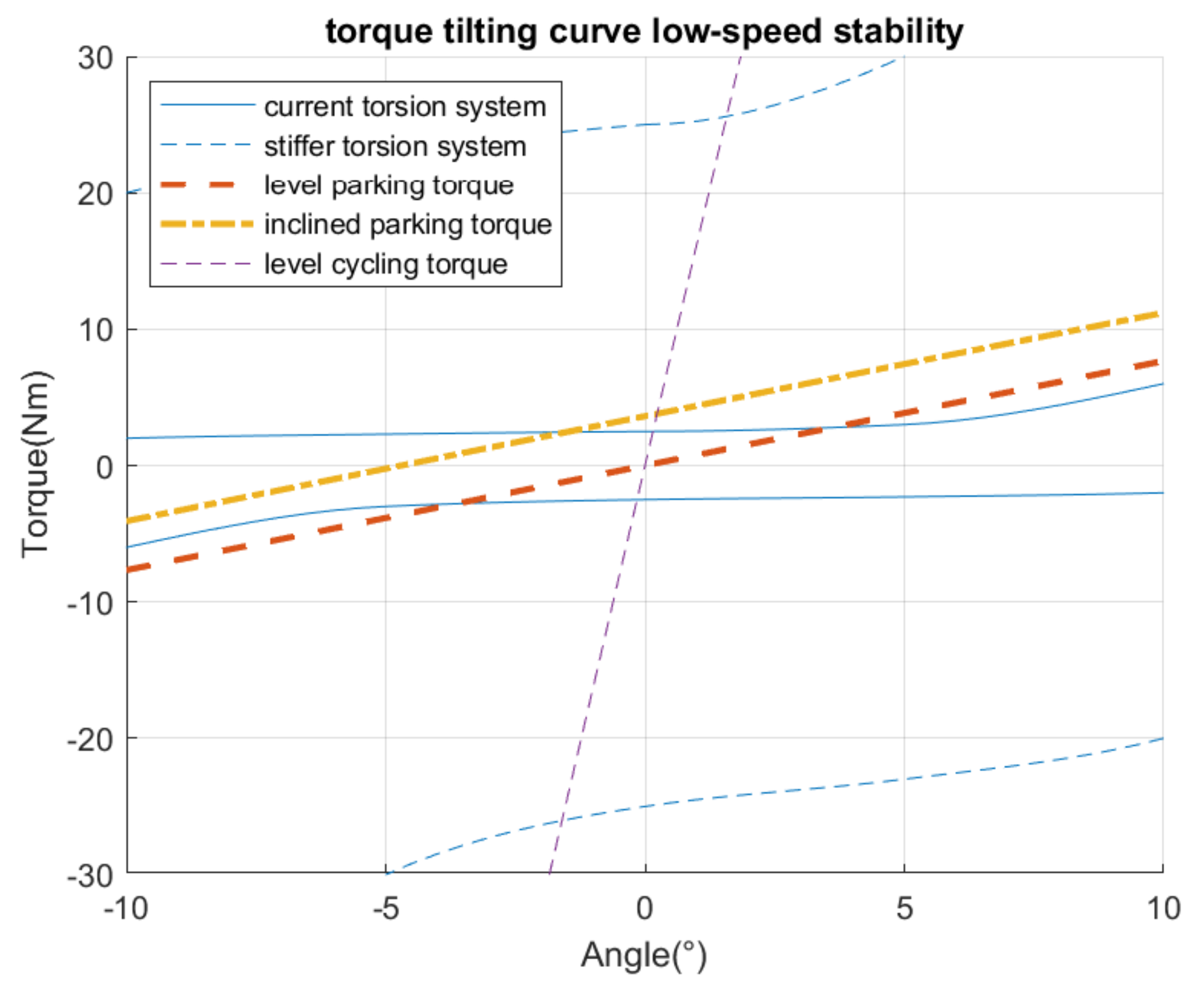
Due to the low torque the torsion system has at near-vertical positions, the improvement in low-speed stability is minimal. Just like with a conventional bicycle, extra concentration is required to cycle at low velocity compared to high velocity. The cyclist experiences a minimal difference with or without the torsion system at low velocity. Cycling above 10 km/h, the vehicle has self-stable properties and does not require the aid of a torsion system to remain upright. Increasing the torque stiffness can improve the low-speed stability and limit the parking tilting, but can limit the ability to tilt while turning. On a traditional bicycle, while cycling a straight line at 9 km/h, the roll angle remains between −1.5° and 1.5° [
16]. To remain stable, the cyclist has to balance by tilting his torso or steering. To aid in the low -speed stability, the torsion system counter-torque should be equal or higher than the to compensate for the imbalance.
The torque created by the imbalance is calculated using Equation (1). Centripetal force is neglected as the stability in a straight line is considered. A rigid cyclist body is considered, meaning the cyclist does not lean in the opposite direction to aid in the balance. At a tilt angle of 1.5°, the driver module with the cyclist generates a torque of 24.39 Nm.
When the torsion system is 10 times stiffer, the counter-torque is higher as can be seen in
Figure 9 and should improve the low-speed stability. This cannot be tested with the current prototype due to the difficulty of changing the torsion system. This stiffer torsion system reduces the tilting when parked but also reduces the ability to tilt while cornering. These changes can be calculated as before.
The changes while tilting due to the stiffer torsion system are calculated using Equation (3). These changes can be seen in
Figure 10.
The stiffer torsion decreases the tilting according to the velocity. The influence is not shown over the complete turning radius as the vehicle’s velocity increases the minimum possible turning radius. During a big turning radius, the stiffer torsion spring causes little tilting reduction. This is a minor change and has a limited influence on the manoeuvrability. However, the influence of the torsion spring increases when the velocity is increased or at a smaller turning radius. In extreme cases, for example when cycling at 25 km/h through a 10 m turning radius, this can reduce the tilting angle by 8°. This results in an increased lateral acceleration of 1.5 m/s
2 which is still considered as a normal driving acceleration [
15]. While cycling normally, the stiffer torsion spring would only account to a tilting reduction of 2°.


