Article

Experimental and Numerical Investigation of a Multifunctional CFRP towards Heat Convection under Aircraft Icing Conditions

by
Maximilian Otto Heinrich Schutzeichel
1,*,
Thorben Strübing
1,
Ozan Tamer
2,
Thomas Kletschkowski
1,
Hans Peter Monner
3,4 and
Michael Sinapius
2
1
Faculty of Engineering and Computer Science, Hamburg University of Applied Sciences, Berliner Tor 9, 20099 Hamburg, Germany
2
Institute of Mechanics and Adaptronics, Technical University Braunschweig, Langer Kamp 6, 38106 Braunschweig, Germany
3
German Aerospace Center, Lilienthalplatz 1, 38108 Braunschweig, Germany
4
Faculty of Mechanical Engineering, Institute of Mechanics, Otto von Guericke University Magdeburg, Universitätsplatz 2, 39106 Magdeburg, Germany
*
Author to whom correspondence should be addressed.
Appl. Mech. 2022, 3(3), 995-1018; https://doi.org/10.3390/applmech3030056
Submission received: 20 June 2022 / Revised: 26 July 2022 / Accepted: 29 July 2022 / Published: 3 August 2022

Abstract

:
A combined experimental and numerical approach for the analysis of convective heat transfer from a multifunctional flat plate specimen under aircraft icing conditions is presented. The experimental setup including a heat control and measurement system that is installed in a de-icing test bed. The ambient temperature ( θ a = [ 253 , 283 ] K ), air velocity ( v a = { 0 , 15 , 30 } m s ), and angle of attack ( α = { 10 , 30 } ) are varied, and their influence on heat transfer during local Joule heating is discussed. The numerical approach utilises the results to compute the convective heat transfer coefficients (HTC) based on Newton’s convective heat transfer condition. Results indicate that the numerical model represents the heat transfer behaviour with high accuracy. The HTC for free convection was found to hold h ¯ 2.5 W m 2 K and h ¯ [ 10 , 40 ] W m 2 K for forced convection conditions with minor scattering. The increase in HTC under forced convection conditions has a significant effect on the overall heat transfer behaviour, resulting in high temperature gradients within the material. The functional optimisation of multifunctional structures will benefit from including application related convection conditions, dealing with resulting temperature fields by structural design. It is expected that multifunctional structures for de-icing as well as for structural energy storage, morphing structures, or stiffness adaptive structures with similar material constituents will benefit from this recognition.

1. Introduction

Multifunctional carbon fibre reinforced plastics (MCFRP) are materials which that one or more functions in addition to their mechanical integrity. These additional functions are based on the intrinsic properties of the constituents of the CFRP. For instance, in addition to superior stiffness and strength, carbon fibres are able to provide electrical current conduction in the longitudinal direction, emit significant Joule heat, and intercalate lithium ions [1,2]. Accordingly, structures made from such multifunctional CFRP materials are able to provide functions without any additional substructure or system being installed on or joined with the CFRP. This fact opens the doors for superior lightweight design potential on a system level, where multiple, classically monofunctional subsystems can be replaced by a multifunctional structure made from multifunctional CFRP materials.
Recent research focused on different application scenarios for MCFRP materials, comprising structural energy storage [3,4,5], morphing (shape changing structure) [6,7], stiffness change and control [8,9], and thermal management, e.g., for de-icing of aircraft wing leading edges [10,11]. De-icing has been identified as causing the most severe thermal load cases, as it comes to heat transfer under forced convection conditions. However, all applications are exposed to free convection or forced convection conditions as well, depending on the individual environment (e.g., aircraft cabin interior or aircraft outer skin). It is noteworthy that MCFRPs are beneficial not only for aircraft structures, but also for all mobility solutions, with the aim for lightweight design (see, e.g., [12]). Significant Joule heat is emitted during functional operation [1,8,13,14], which dominates the temperature rise inside the material. This is either desired (e.g., de-icing, stiffness control, morphing, prewarming of structural batteries) or needs to be limited (cooling of structural batteries during operation). The transient and stationary temperature field in the MCFRP is coupled with other physical fields of the material. This comprises, for instance, the thermo-mechanical stiffness changes [1,15,16] and the influences on electro-chemical transport processes [13,14].
Accordingly, the temperature field and especially its high dependence on the heat transfer to the environment needs to be well understood. This boundary condition (BC) is usually assumed or estimated in numerical analysis based on standard parameter ranges from literature (e.g., [17]). The lack of information about heat transfer to the environment from MCFRP was highlighted [11,14]. In addition, industrial adoption of these emerging technologies requires a clear demonstration of energy efficiency and weight saving potential compared to “off the shelf solutions”. For instance, the energy consumption of the MCFRP equipped aircraft wing leading edge for de-icing can only be estimated and subsequently be minimised by computational methods, when operational and environmental BCs are known. This work aims at the characterisation of the convective heat transfer behaviour under aircraft icing conditions with in-situ measurements.
Without measurements, the heat transfer from a solid to air can only be predicted by surrogate models with respect to predefined lab conditions, as the individual combination of environment, material, geometry, temperature, and convective medium directly influence the heat transfer path in case of heat convection [18,19]. However, as the described MCFRP utilise similar constituents (carbon fibres (CF), polymeric matrix materials, and glass fibre fabrics for separators), the characterisation in this work is believed to impact research for all application scenarios stated above.
The conditions for icing of aircraft wing leading edges are characterised by low ambient temperatures θ a = [ 253 , 283 ] K and airflow around the airfoil [20]. These conditions are established in the de-icing test facility at TU Braunschweig (see Section 2.3.2). The MCFRP specimen structure is designed as a flat plate with laminated architecture (see Section 2.2). The flat plate-type specimen has been investigated in heat convection test setups for free convection (e.g., [21]) as well as for forced convection under controlled flow-conditions (e.g., [22,23]). In addition, this suits well to the state of the art, considering flat plate-like structural batteries at the coupon level, as demonstrated recently [24].
The present work investigates the thermal convection behaviour of the MCFRP flat plate structure under aircraft icing conditions with a combined experimental and numerical approach. The main driver of maturation is computational design, analysis, and optimisation of MCFRP, which highly depends on the heat transfer coefficient (HTC) h in thermally coupled analysis [11,14]. Accordingly, the HTC is examined in this study towards free and forced convection conditions as well as effects from ambient temperature θ a , airflow velocity v a , and angle of attack α . These results will underpin the design and energetic optimisation of de-icing as well as the design of other MCFRP application scenarios in future research.
This work is further outlined by a methodology section (Section 2) describing the experimental and numerical setup, and a results section (Section 3) presenting experimental and numerical results as well as the analysis of the convection parameter h towards influencing parameters. This is followed by a discussion in Section 4, classifying these results within the state of the art and discussing their effect on MCFRP development. The work is completed with the conclusions and future research in Section 5.

2. Methodology

2.1. Combined Experimental and Numerical Approach

The approach for the experimental and numerical investigation of the convective heat transfer at the surface of a MCFRP flat plate specimen is derived from the transient heat transfer equation:
c ρ t θ ( x , t ) · ( λ · θ ( x , t ) ) = Q ,
where c is the mass specific heat, ρ is the density, λ is the thermal conductivity tensor (in case of anisotropic heat transfer behviour of MCFRP [11]), θ is the local temperature, and Q is the sum of generated and lost volumetric heat. For solving the transient heat equation, a number of BCs can be applied. In this case, heat generation is assumed based on Joule heating Q gen , and heat loss is assumed to be reduced to convective heat transfer Q con to the environment and radiative heat loss Q con :
Q gen = κ | J · J |
Q con = h · A · ( θ θ a ) ,
Q rad = σ · ε · A · ( θ 4 θ a 4 )
where J is the vector of the electric current density, κ is the specific electrical resistance, A is the related surface where heat is transferred, h is the heat transfer coefficient, θ a is the ambient temperature, σ is the Stefan–Boltzmann constant, and ε is the emissivity of the material. Related to the present problem, all material constants are assumed to be available. Once a constant DC current I is applied, heat is generated until a stationary heat transfer to the environment is reached. At a physical specimen, the heat loss due to radiation can be identified by measuring the ambient temperature θ a and the surface temperature θ , in the case where emissivity ε and radiating surface area A are known. The same holds for the convective heat transfer. However, as stated above, the heat transfer coefficient h is usually not known and is therefore assumed.
The investigation here is set up to use a flat plate specimen, of which all constants in Equations (1)–(4) are known, except the heat transfer coefficient. Simultaneously, a virtual geometric representation is set up, which can be used for computation of the given thermal problem. The measured results of the applied current and the stationary temperature distribution on the surface of the flat plate are fed into the computational model as boundary conditions. Then, the corresponding HTC is the only unknown and can be predicted. The next section introduces the flat plate specimen. In Section 2.4, these assumptions are taken, and the numerical approach is described in detail.

2.2. Flat Plate Specimen Production and Properties

The flat plate specimen is made from TohoTenax IMS65 carbon fibre rovings [25], 200 g m 2 glas fibre (GF) fabric from Interglas (Nr. 05507) [26], and epoxy resin L 20 with hardener W 300 from R&G Composite Technology [27]. Figure 1a shows the prepared flat plate with production steps I–III and marked measurement area A m , Figure 1b introduces the virtual geometry with identical surface area A m and indication of the single laminate layers and compounds, and Figure 1c provides the exact dimensions of A m , where t p indicates the thickness of the plate.
The laminate consists of nine layers of glass fibre fabric (1) and a tenth top layer, which comprises four rovings of 24k IMS65 carbon fibres (2). Spaces between the rovings are filled with glass fibre fabric (1) (compare Figure 1b). It should be noted that the top layer is divided into two separate domains for the model geometry only (see Figure 1b). This separation is related to the modelling of “active” (Joule heating) and “passive” domains, which is explained further in Section 2.4.2. Together, these two domains represent the tenth top layer of the flat plate specimen. The whole plate is produced in a hand laminate process and is cured under vacuum at room temperature (Step I). The plate’s dimensions are 900 mm × 300 mm × 2.2 mm total. The number of nine layers of glass fibre fabric was chosen to provide at least 2 mm thickness for structural integrity of the plate. The detailed indication of the flat plate’s architecture and dimensions is used further for the geometry and material representation in the numerical model (see Section 2.4.2).
After curing, the overhanging ends of the CF rovings are connected to two copper current collectors in step II, which are mounted on the back side of the plate. Both reliable electrical and mechanical connections to the current collectors are realised by conductive epoxy resin TDS CW2460 by Chemtronics [28] (see Figure 1a, step II). This method was proven in a previous work by the authors [1]. In step III, the surface of the plate is coated with heat consistent matte black paint to establish a homogeneous emissivity for thermal radiation (see Figure 1a, step III). Information about emissivity of the surface is given in the validation procedure of the thermal measurement in Section 2.3.1. All details about material properties, volume ratios, and processing parameters can be found in Appendix A.
The temperature measurement area A m is placed in the middle of the flat plate at position w c 0 = 110 mm . The copper current collectors on the back side are used to connect the CF rovings to the measurement and control system (see Section 2.3.1). The virtual geometry represents exactly the surface area A m and the material architecture underneath, indicated by the given coordinate system (compare Figure 1a,b). The whole test setup is finally installed within the de-icing test bed (see Section 2.3.2), described subsequently.

2.3. Experimental Setup

2.3.1. Thermal Measurement and Control System

The structure and function of the measurement and control system are specifically developed for this work according to VDI/VDE2206 [29]. Figure 2 shows the general setup for the measurement and control of thermal heating and temperature measurement at the flat plate. To control the heating current, a pulse-width modulated signal (PWM) is used, which is provided by a microcontroller (Arduino Mega 2560). The PWM level is amplified by a MOSFET circuit to adapt the connected supply voltage U. Due to the DC component of the amplified voltage signal, a tailored power can be converted at a DC resistor. The DC value of the periodic voltage signal u ( t ) is calculated as a function of the present duty cycle p:
U ¯ = 1 T 0 T u ( t ) d t = 1 T 0 p · T U d t + p · T T 0 V d t = p · U ,
where U ¯ is the mean output voltage, T is the period duration, and U is the source voltage [30]. The MCFRP, in particular the embedded CFs, are assumed to behave like an ohmic resistor [1], which results in a proportional current versus voltage curve. Therefore, the applied current I ¯ is defined to be constant for given source voltage U and a known consumer resistance R p :
I ¯ = p · I = p · U R p .
For the measurement of a temperature field θ m ( x , y , t ) at the surface of the flat plate A m , an inhomogeneous and unknown emissivity distribution of the surface is one of the most important reasons for unreliable temperature measurements [31]. The thermographic camera system Flir E60, enabling superior connectivity to MATLAB, is set up to indicate the radiation based on a constant emissivity ε ( x , y ) = const over the entire measurement area (compare Figure 1 and Figure 2). The emissivity of the measurement surface is required to approach the emissivity of a black body, ε ( x , y ) 1 , with a matte surface [31]. Accordingly, the reflected radiation of the surface is minimised and can be assumed to not be part of the indicated thermal image.
This condition is set up by coating the flat plate’s surface with commercially available, thermally solid, matte black paint according to Cardenas Garcia’s procedure [32]. Accordingly, the emissivity of the resulting surface is assumed to hold ε ( x , y ) = 0.972 ± 0.012 in the long-wave infrared range, which was verified according to the procedure given in Appendix B. All surfaces in the de-icing test facility (described in Section 2.3.2) are assumed to have ambient temperature θ a . The total radiation is a combination of reflected ambient radiation (e.g., from exterior surfaces) and emitted radiation of the specimen. It is assumed that all reflected radiation is related to ambient temperature. This part of the total radiation is compensated for by the camera, which receives the ambient temperature as an input value. In addition, the normal distance between the flat plate’s surface and the camera is set to d m = 0.4 m . The measured or controlled quantities ( θ a , I ¯ a , and p) are analysed towards their reliability and were found to be in good agreement with actual values. Furthermore, the resistance of the CF rovings, embedded in the flat plate, was determined to hold R fp = 4.2 Ω . For more details on the verification and on the measurement and control procedures, see Appendix B. The next subsection describes the de-icing test facility, including the installation of this setup together with the flat plate specimen.

2.3.2. Setup in the De-Icing Test Facility

The experimental investigation of the functional model was carried out in the de-icing test facility (Figure 3), which has an Eiffel-type wind tunnel. The equipment is placed in a cooling chamber with internal dimensions of 3 m × 3 m × 8 m. The wind tunnel has a modular structure. The purpose of such a design is to enable the exchange of the individual segments. Furthermore, it is also possible to install additional devices or to modify a module [33]. The setpoint specifications, such as the air temperature, the wind speed, and spray bar water pressure (for impact ice applications) in the test chamber are entered via the control station computer. The wind speed in the measuring section is calculated from a calibrated differential pressure measurement [34]. One measuring point for the pressure is before the airflow enters the measuring chamber, and the second one is at the intersecting point between modules 4 and 5.
Module (5) contains the water injection system, which consists of three bars, each equipped with five nozzles. In the contraction module (4), the airflow with the sprayed droplets is accelerated towards module (3). Module (3) has the test chamber inside, where air (with or without water droplets) flows. Between the test chamber and the exterior casing of module (3) there are aluminum profiles on both sides, which allow the test bench to be installed. The aluminum profile on the top of the test chamber serves to mount a camera for monitoring the experiment. Module (2) is the diffuser module that expands the flow towards Module (1), ventilation fan [33].
The operating characteristics of the de-icing test facility for the boundary conditions of the conducted experiments are listed in Table 1.
Figure 4 presents the flat plate specimen (1) attached at both ends in the test chamber (2). The actual temperature of the air is measured with a temperature sensor (PT100) in the test chamber (3). The surface temperature of the plate is monitored with the thermal imaging camera (Flir E60) (4), which is fixed at the top, outside the chamber. The test chamber is separated from the camera by a thin plate (7). This plate is equipped with a circular hole such that the perspective of the camera on the flat plate specimen is not truncated. The angle of attack α is defined positive versus the horizontal airflow (see Figure 4a). The test plate is further equipped with wood beams on the back side (5) in order to make it robust against airflow loads. Furthermore, on the back side of the measurement area A m , a 40 mm thick layer of polystyrene foam (6) is used to minimise heat transfer at the back surface.
This is important for the assumption of an adiabatic boundary condition in the numerical model (see Section 2.4). Further influence on the thermal behaviour by the wood beams is assumed to be negligible, which is verified during results discussion (see Section 3).

2.3.3. Free and Forced Convection Test Configurations

The convection test configurations are chosen to cover free and forced convection as well as the typical environmental factors. Table 2 contains the defined numbers for angle of attack α and air velocity v a as well as the interval for the set ambient temperature θ s in increments of 5 K, respectively.
In total, 25 different configurations are tested, where the free convection case is only evaluated for v a = 0 m s . This enables the analysis of the influences from these environmental conditions on the convective heat transfer behaviour. Air velocity v a and ambient temperature θ a are measured and controlled throughout each case. In subsequent results analysis, the combination of these parameters is always stated by nominal and measured (recorded) values.
For the Joule heating process, a fixed DC mean current of I ¯ = 2 A , as defined in Equation (6), is applied and measured. During the heat-up process, the measured mean current I ¯ m ( t ) as well as the temperature field θ m ( x , y , t ) are recorded time-discretely with a frequency of 2 Hz. This frequency is suitable, as the thermal processes are slow. The temperature field of the controlled and measured surface area A m is resolved by the resolution of the thermographic camera with 320 × 240 pixels, which corresponds to the y and x axes, respectively (see Figure 1). This enables the analysis of the transient heat-up process and the identification of the stationary heat transfer condition for results analysis.
The results are presented in Section 3. The measured current I ¯ m ( t ) and temperature fields θ m ( x , y , t ) are further processed, and chosen conditions thereof are applied as boundary conditions for numerical analysis (see Section 2.4.2) hereinafter.

2.4. Numerical Modelling

2.4.1. Computational Model for Stationary Heat Transfer

The investigation of the heat transfer coefficient is based on the assumption that a control volume of the flat plate specimen can be represented in a numerical model, which is able to cover the governing material laws for the thermal processes, the influencing material, properties and thermal boundary conditions. Based on the transient heat transfer Equation (1), the stationary case can be defined for t θ = 0 in a discrete homogenised material domain to
( λ i · θ ( x i ) ) = Q i , with x i Ω i
where λ i is the effective heat conductivity tensor of domain Ω i , θ ( x i ) is the stationary temperature at a spatial point in domain Ω i , and Q i represents the sum of the local volumetric heat sources and sinks (compare former work of the authors [11]). The discrete, stationary heat transfer problem can be solved by the finite element method for arbitrary geometries using, e.g., Comsol Multiphysics, which is used for this work in version 6. Comsol Multiphysics is a commercial software used for coupled physics simulations based on the finite element method, comprising also the heat transfer equation and all related modelling tools. Furthermore, MATLAB is used to analyse measured data and transfer such data to Comsol Multiphysics via MATLAB LiveLink. The model boundary conditions and assumptions, e.g., homogenisation methods for GF and CF composite plies, are defined such that the resulting temperature field can represent the state identified by experimental investigations at the flat plate specimen (see Section 2.4.2).
However, the experimental work described previously represents a transient heat-up process until a stationary heat transfer is reached over time. The stationary case is given at that point of time, when the change of maximum temperature at the surface of the specimen m a x [ θ ( x , y , t ) ] is minimal. This condition is defined here by the point of time when the minimum of the empirical variance ϑ (called “variance” hereinafter) of the desired quantity is found. Therefore the variance is computed as
ϑ k ( t i ) = 1 n 1 i = k n ( θ max ( x , y , t i ) θ ¯ max ) 2 with n = k + 40
where t i denotes a point in time in the measurement interval, θ max ( x , y , t i ) is the maximum temperature of the field at time t i , θ ¯ max is the mean value of related temperature maxima, and [ k , k + 40 ] is the chosen data interval over time with a length of 40 data steps. This length corresponds to a time interval of 20 s, because the scanning frequency was set to 2 Hz. The variance is computed for the total number of k time intervals in the dataset. The stationary maximum temperature is then θ max , stat = θ max ( x , y , t s ) , where t s is the point in time where the minimum of ϑ k is found. With this definition, θ max , stat can be compared with the solution of the stationary temperature field of the model.
However, the computed temperature field is dependent on the boundary conditions, which are defined together with further model assumptions in the following subsection.

2.4.2. Assumptions and Boundary Conditions

As described in Section 2.1 and 
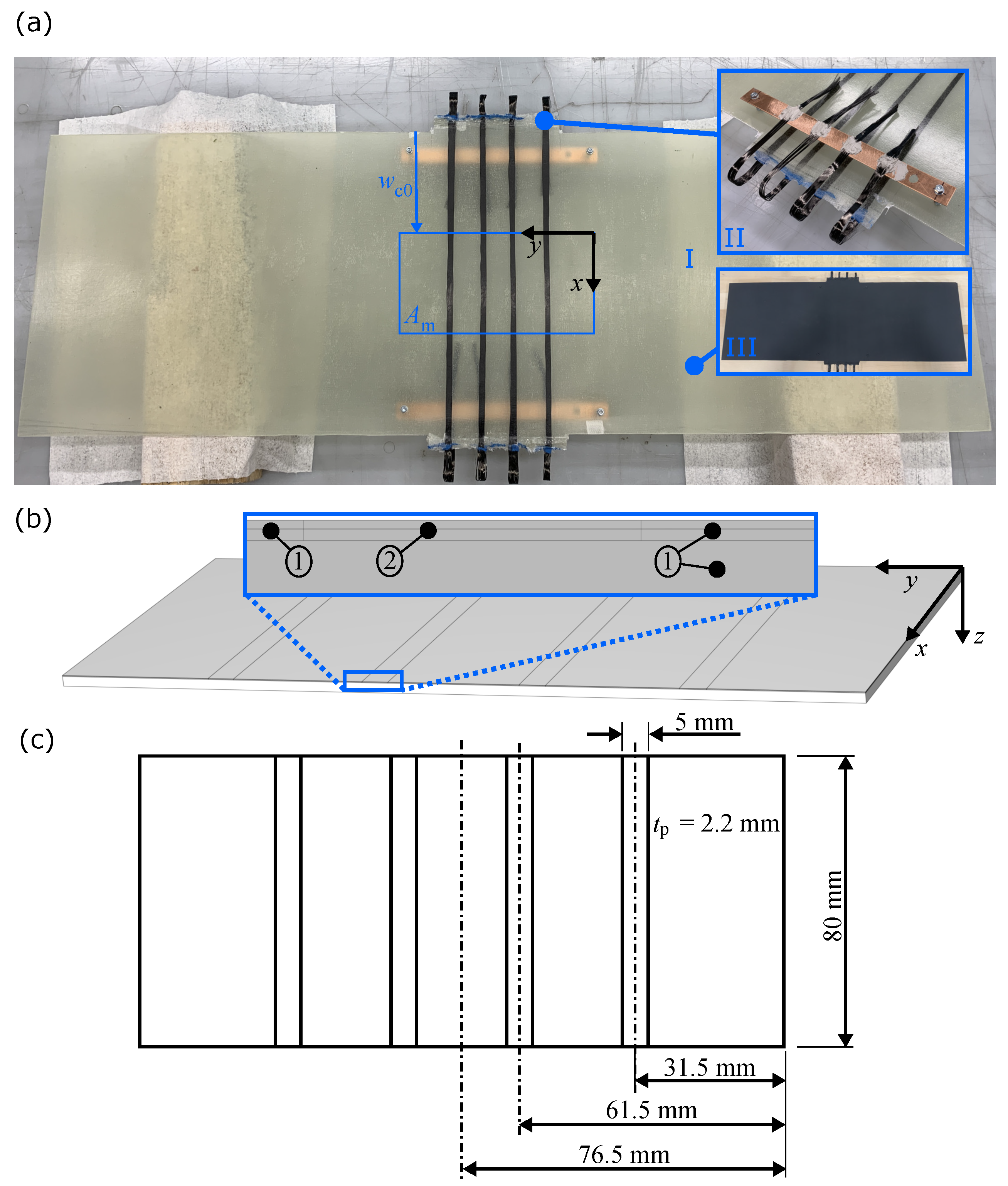
Section 2.2, the control volume is related to the measured surface area A m in x y z -coordinates. The control volume is shown again in Figure 5a with indicated boundaries, which are named by the respective coordinate axis surface normals ( X , X + , Y , Y + , Z , Z + , related to x, y, z coordinates, respectively). In Figure 5b, a closeup of the three different domains is given: Ω 1 —the passive CF composite layers, Ω 2 —the active CF composite layers, and Ω 3 —the passive glass fibre composite layers. “Active” indicates here that Joule heating by current conduction is applied to this domain, whereas the passive domains are electrically inactive.
The domains Ω 1 and Ω 2 are separated only to define the active volume, where Joule heat is emitted. The volume ratio of these domains is defined as follows:
v Ω 2 = V Ω 2 V Ω 1 + V Ω 2 : = v cf ,
where V Ω i are the respective domain volumes and v cf is the carbon fibre volume ratio in the top layer of the laminate (compare Table 3 and Figure 5). Accordingly, V Ω 2 is exactly the volume of the CFs applied for Joule heating (4× 24k carbon fibre rovings, compare Section 2.2). This definition is reasonable, as the volume (length and cross sectional area) define the effective resistance of the carbon fibres, thus governing Joule heat emission [1].
The material properties are defined as effective properties related to thermal conductivities resulting from fibre orientation in the laminate (see Table 3). According to earlier work of Schutzeichel et al. [1], Ω 1 and Ω 2 are assumed to be thermally transversal isotropic, where the longitudinal direction of the unidirectional (UD) CFs is related to the x-axis here. The GF composite domain is effectively isotropic, as the thermal conductivity is identical for all directions. This can be reduced to the low thermal conductivities of both GF and epoxy resin.
The domain related fibre volume fractions v x , resulting effective thermal conductivities λ ¯ , and the specific electrical resistances κ for the single domains are given in Table 3. The indices indicate the constituents as well as the effective direction or plane. It should be noted that the fibre volume fractions were determined by thermogravimetric analysis of material specimens taken from the flat plate after the described measurements were finished. As the CF and GF composite domains are two-phase material domains, the rule of mixture (ROM) is used for longitudinal ‖ as well as transversal ⊥ isotropic effective properties, which results in proper measures according to [11]. To apply current conduction only to Ω 2 , specific electrical resistances of Ω 1 and Ω 3 are set to infinity. All constituents’ properties feeding into the effective properties are given in Appendix A.
In addition to domain and material property definitions, the BCs are essential in this approach to achieve a proper calculation of the heat transfer coefficient. The thermal BCs should represent the conditions during the experimental investigation (see Section 2.3.2) and are defined as follows:
d θ x 0 = θ ( X + ) θ ( X ) = 0 ,
θ ( Y + ) = θ ( Y ) = θ a ,
q ( Z + ) = n z · Q , with Q = 0 ,
q c ( Z ) = n z · h · A · ( θ a θ ) ,
q r ( Z ) = n z · ε · σ · A · ( θ a 4 θ 4 ) ,
where d θ x 0 indicates a periodic BC, q indicates a boundary inward heat flux with inward surface normal n z in z-direction, A is the local surface area, h is the HTC, σ is the Stefan–Boltzmann constant, and ε is the emissivity of the surface. Indices c and r denote convective and radiative, respectively. All conditions are related to the boundaries defined in Figure 5 for all domains Ω 1 Ω 3 . The back side of the control volume is defined to be thermally adiabatic, which is reasonable, as the back side of the flat plate was covered to minimise thermal heat transfer (compare Section 2.3.2). The periodic BC is chosen, as this volume element is repeatable along the x direction of the flat plate. The boundaries Y + and Y are defined to hold ambient temperature. Results of the experimental measurements indicate this assumption (see Section 3.1). The BC on the surface A m is defined as Newton’s convective heat transfer law (Equation (14)). In addition to the convective heat transfer at the surface, thermal radiation is also assumed based on the defined emissivity ε = 0.972 (see Section 2.3.1).
Because ambient temperature θ a and the local surface area A are known, the resulting temperature at the surface θ is only controlled by the HTC h. This enables the comparison of the measured maximum stationary temperature θ max , stat from the experimental investigation (as defined in Section 2.4.1) and the computed maximum temperature on the surface of the control volume θ max , c = m a x [ θ ( x , y , z = 0 ) ] . Accordingly, h is tailored in an iterative procedure to minimise the difference between θ max , c and θ max , stat until a quality criterion c is reached:
d θ = | θ max , c θ max , stat | c .
The criterion is defined here to hold c = 0.5 K , which is reasonable compared to the accuracy of the measured results.
In addition to the thermal BC and HTC evaluation, the volumetric heat source needs to be defined via Joule heating in the active carbon fibre domain Ω 2 :
Q p = κ | J · J | , with
J = j · n x = I ¯ m 4 · A cf · n x with n x Ω 2
where J is the vector of the electric current density, which is given by a constant electrical current density j and the inward surface normal n x at surface X in domain Ω 2 . The current density is related to the applied heating current I ¯ m , set to the value measured during the experimental process (compare Section 2.3.3), and the cross-sectional area of the four carbon fibre rovings 4 · A cf embedded in the flat plate, where
A cf = 24.000 · π · d f 2 4
is based on the assumption of 24,000 fibres at each bundle with fibre diameter d f = 5 μ m [35].
With this setup, the HTC is computed for all 25 stationary heat transfer cases defined in the experimental investigation. Furthermore, the HTC is evaluated towards the influence of the environmental conditions. All results are presented in the following section.

3. Results

3.1. Measured Temperature Distributions

The results of the individual experimental measurements are presented in time-discrete temperature distributions θ m ( x , y , t ) , which provide the temperature field at the surface of A m with a sampling frequency of 2 Hz. For the calculation of the heat transfer coefficient based on the numerical model, the stationary heat transfer condition needs to be identified.
The variance is computed for all k time intervals in the total number of maximum temperatures t a (see Equation (8)). The minimum of the variance m i n ( ϑ ( t ) ) is identified, and the corresponding point in time of stationary heat transfer t s is indicated. Figure 6a shows an example of the temperature rise over time θ max , meas with related variance ϑ . The heat-up process follows, as expected, an exponential saturation curve, which develops a stationary temperature over time. The stationary case is identified here for the minimum variance at t s = 149 s . For each case, the set temperature θ s , the applied air velocity v a , the angle of attack α , and the measured ambient temperature θ a are given. The headline provides a unique case number (K16) for these conditions and related t s . Figure 6b shows an example of the stationary temperature distribution θ m ( t s = 149 s ) , plotted over the measured area A m and related to x y coordinates (compare Figure 1).
The following general observations can be made regarding the measured stationary temperature distributions (exemplary given in Figure 6b):
  • The maximum temperatures occur along the heat emitting CF rovings.
  • The minimum temperatures occur at the boundaries y = { 0 , 153 } mm and are equal to the ambient temperature θ a .
  • The temperature drop in between the CF rovings indicates that the heat transfer at the flat plate is dominated by convection to the environment. The heat conduction within the flat plate is limited due to the low effective heat conductivity of the material constituents.
  • In general, the temperature distribution appears homogeneous along the x-axis. Slight variances, especially along the CF rovings, are reduced here to manufacturing inaccuracies. However, this indicates a homogeneous heat transfer in the control area (across the material domains as well as to the environment), which belongs to a non-changing airflow boundary near to the surface [23,36].
For the last observation, it should be noted that the aerodynamic boundary layer near to the surface of the flat plate can affect the heat transfer behaviour. As the temperature distribution is found to be homogeneous in the airflow direction, it is assumed that the heat transfer and the corresponding HTC are not affected by airflow boundary layer effects in our study. This condition is observed for all evaluated cases throughout this study. An overview about the stationary heat distributions is presented in Figure 7, where the graphs distributed along θ a and v a increase at constant angle of attack α = 10 . Primary effects concerning the influence of different ambient conditions can be observed:
  • With increasing ambient temperature θ a , the local temperature peaks increase.
  • With increasing air velocity v a (forced convection), the local temperature peaks decrease significantly. Furthermore, the local temperature minima become wider.
  • Maximum temperature gradients in the y-direction ( θ y ) increase with the increase in air velocity v a (forced convection).
  • The temperature variance along the x-axis (at y = const.) increases with v a , and manufacturing defects become more pronounced.
These observations indicate a significant influence of ambient conditions on the heat distribution at the surface of the control area. More precisely, the heat transfer from the heat source along the domains to the surroundings is significantly dominated by convection. Due to low heat conductivities of the composite (see Section 2.4.2), the stationary temperature field is determined by the discrete distribution of heating carbon fibre rovings.
The next subsection provides the computational results from the numerical model, which utilises the presented measured, stationary temperature distributions for the computation of the heat transfer coefficients. Furthermore, the HTC behaviour is analysed versus the applied ambient conditions.

3.2. Predicted Heat Convection Coefficients

The numerical problem is solved in Comsol Multiphysics. With the help from MATLAB LiveLink, the measured stationary temperature distribution θ m ( x , y , t s ) and the computed temperature distribution θ c ( x , y ) are adjusted. Therefore, the heat transfer coefficient h is varied in an iterative process, and the corresponding computational result is compared with the measured data.
The HTC is then optimised until the curves match the quality criterion c, which is related to the maximum temperature at the surface (see Equation (15)). One example is given in Figure 8a, where the computed temperature distribution is given. This result can be compared with the measured distribution, given in Figure 6. To better indicate the results, the temperature profile is compared at position x = const. (see Figure 8b). This position is related to θ max , meas based on the measured temperature data. The resulting HTC, corresponding to this stationary temperature condition, is computed as h = 11 W m 2 K . Slight differences between measured and computed curves are found in the position of the outer temperature maxima, which is reduced to not perfectly aligned roving distributions at the flat plate specimen. Furthermore, the outer maxima are slightly lower in the measured curve, which may be related to small inaccuracies in current distribution to the four heating CF rovings. However, accounting for the overall fit of the curves, the numerical approach is found to represent the experimental results properly.
Apart from this general proof, the different effects of the environmental conditions are analysed further. Therefore, Figure 9 presents an overview on computed and measured results (same number of conditions as given in Figure 7, with α = 10 ). The environmental conditions are given for each case.
For free convection (first column), the representation of the measured temperature distribution is best near to the local temperature maxima and in areas where the temperature gradient θ y shows a high magnitude. In the areas of local minima, the measured temperature is higher compared to the computed results. This is reduced to the effect of heat transfer within the material, which appears to be more pronounced for free convection. This condition is indicated by an HTC of h = [ 2.2 , 2.8 ] W m 2 K (see, in addition, Table 4). Furthermore, these more pronounced minima indicate a slightly underestimated effective heat conductivity applied in the model. This is reduced to ROM related inaccuracies, which represent a lower boundary of actual effective heat conductivity of the composite material. For this study, the result is appropriate, as the influence of internal heat flux is small compared to the heat transfer to the environment. In addition, it should be noted that the heat transfer coefficient shows only minor variation with temperature (see Table 4).
Apart from free convection, the HTCs of all forced convection conditions are presented in Table 5, where each line corresponds to a specified setup of v a and α . The first row provides the corresponding set ambient temperatures θ s . In Figure 9, the second and third column are related to forced convection conditions. The local minima are more accurately represented. The internal heat transfer process is less pronounced compared to the free convection case, as the heat transfer to the environment dominates the stationary temperature distributions. For all curves, the measured temperature drops down to ambient temperature at the outer boundaries ( y = { 0 , 153 } mm ). This justifies the boundary condition defined in Equation (11). As already indicated, the production related inaccuracies (variant temperature maxima for the different CF rovings) are indicated here again, which are not represented by the model. However, the overall representation of the temperature distribution is found to fit well to the measured distribution for all cases. In addition, no influence by the installed, reinforcing wood beams (see Figure 2) is indicated. Accordingly, the corresponding, predicted HTC are assumed to be a proper representation of the actual values. The general variability of the HTC is analysed further.
With respect to the indication for free convection, it is found that the HTC is not proportional to ambient temperature θ a . The slight variation of HTC versus temperature is reduced to inaccuracies in the measurement chain. To further analyse these effects, the mean values of HTC over temperature h ¯ are computed, and the results are given as bar plots with related standard deviation indicated by error bars (see Figure 10).
First of all, the HTC is significantly increased in case of forced convection compared to free convection ( v a = 0 m s ). For v a = 30 m s , the HTC is up to 17 times larger. However, the measurement inaccuracy is increased as well, which is indicated by a more pronounced standard deviation. This is understood here to be related to aerodynamic effects such as turbulence in the air stream and to the resulting dynamic mechanical loads at the flat plate specimen (e.g., vibration). In any case, the standard deviation is small enough to assume temperature independent HTCs in the applied ambient temperature interval of θ a = [ 253 , 283 ] K .
In addition to these influences, the angle of attack α can be analysed towards its effects on the HTC. Figure 11 shows the different HTCs for α = 10 and α = 30 related to (a) v a = 15 m s and (b) v a = 30 m s . A general observation is a significant decrease in HTC with increased α . This is, again, more pronounced with increasing air velocity. Accordingly, the highest heat transfer coefficient is expected at low angles of attack versus the surface. Furthermore, the standard deviation is larger at high air velocities, also for α = 30 . This supports the interpretation of larger measurement inaccuracy due to dynamic air loads.
In summary, this analysis shows reliable results of heat transfer coefficients under aircraft icing conditions. The computational results show good agreement with temperature distributions measured at the flat plate specimen. Some inaccuracies are reduced to the hand lamination production process of the specimen and to the overall uncertainty of the measurement chain. However, the indicated heat transfer effects enable a valuable interpretation towards MCFRP development and application (e.g., for de-icing) hereinafter.

4. Discussion

The interpretation and discussion of the results can be divided into the general evaluation with respect to the state of research and the discussion of these results towards their importance for MCFRP application scenarios.
Based on these results, it is expected that heat is primarily transferred from the heat source to the environment and that internal heat transfer processes are minor. This is a typical observation for low heat conductivity materials, which are not able to distribute the thermal energy when the heat sink, given here with heat transfer by convection, is large. However, the resulting temperature distributions (measured and computed) indicate a proper temperature increase at the surface of the laminate, although the heat conductivity is small. This is primarily given near to the active fibres, which results in a nearly static temperature in the x-direction (see, e.g., Figure 9). Such nearly homogeneous stationary temperatures are typical for heated CFRPs [15], which is a benefit for heating applications (e.g., de-icing). Nevertheless, the areas without active CF rovings show significant temperature drops. However, the local heating of the fibre reinforced plastic and the resulting temperature distribution can be predicted with the simple Newton-type boundary condition, although this assumes a constant HTC for the whole surface (see Equation (14)).
In addition, the computed heat transfer coefficients are found to be in expected value ranges. Free and forced convection HTCs are usually given in intervals of [ 1 , 10 ] W m 2 K and [ 20 , 100 ] W m 2 K , respectively [17,18,37]. This recognition provides confidence about the results in terms of reliability. However, it can be seen that the forced convection HTCs for v a = 15 m s are between typical free and forced convection parameters. At the same time, it is indicated that the forced convection stationary temperature distribution is already significantly influenced compared to free convection HTCs. This highlights the fact that in the case of MCFRPs, including low material heat conductivities, a well resolved HTC determination is needed to represent actual boundary conditions in structure modelling and design.
In addition to these general observations, the possible influence of aerodynamic effects is discussed. First of all, some HTC variations are reduced to inaccuracies in the measurement chain, e.g., due to dynamic excitation by air loads. This is plausible since an increase in standard deviation was found for increased air velocity v a (see Figure 10). However, aerodynamic boundaries, e.g., laminar or turbulent boundary layers near to the surface or degree of turbulence in the free air stream, can have an influence on the convective heat transfer [23]. In this investigation, the temperature distribution is found to be invariant along the airflow direction (x direction). This indicates that the HTC of forced convection does not change locally, which is related to a constant boundary layer next to the surface. This is suitable to the expectation, as the boundary layer at the surface of this plate will usually not detach due to the applied angle of attack [22]. Accordingly, the computed HTC values can be understood as mean values over the surface of the flat plate with a constant air boundary layer.
However, in areas of detached boundary layers, the HTC can drop, which would result in a local HTC distribution [22]. Although this is not indicated here, the computed HTCs can be understood as ideal cases for heat transfer with an ideal air boundary layer near to the surface. Furthermore, for a given air stream, the maximum forced convection HTC is expected to be present for attached boundary layers at small angles of attack, as the HTC was found here to decrease significantly with increased angle of attack (see Figure 11). This is comparable to results from Test et al. [22,38], which again support the reliability of these results.
Apart from the quantitative results of heat transfer coefficients, the recognised effects contribute to research concerning multifunctional materials and structures. The results of this study are, in particular, important for the development of de-icing systems for aircraft aerodynamic surfaces made from MCFRP composites. The application of heating carbon fibres within the composite material leads to temperature distributions, which are dependent on the carbon fibre distribution within the structure. This is indicated by the analysed stationary temperature distributions at the surface of the flat plate (see Figure 7). However, former investigations of the authors, dealing with the temperature distribution within the material domain, indicated HTC proportional temperature gradients within the domain (e.g., thickness direction [11]). Combined with temperature sensitive stiffness and thermal expansion of the material constituents, these variant temperature fields play an important role for the multiphysical load scenario in material modelling (e.g., thermal and mechanical loads simultaneously).
For de-icing systems in aircraft wing leading edges based on MCFRP (e.g., [10]), the results here are important for the functional optimisation. For instance, the distribution of heating fibres can be optimised towards an ideal temperature distribution, which simultaneously supports a minimised number of fibres. This would lead to a MCFRP architecture that performs energy efficiently during de-icing operation and reduces the material effort (lightweight design). Because the active heating layer is part of the load bearing structure, no additional materials or system installations are needed, which again increases the benefit. Accordingly, energy inefficient, oversized solutions for the de-icing functionality can be avoided. Therefore, the knowledge of heat transfer coefficients under aircraft icing conditions has a big impact on further model based innovation towards energy efficient thermal management (de-icing) solutions.
Apart from de-icing, this contributes further to other thermally coupled functions provided by MCFRP (e.g., structural batteries, morphing applications, and adaptive stiffness composites). These applications are usually optimised towards their multifunctional performance (e.g., structural integrity and energy storage capacity in the case of structural batteries [3]). The electrical current conducting CFs and, in addition, electro-chemical processes, generate heat, which always results in temperature distributions within the material domains (see, e.g., [14]). Especially, the general property of low effective heat conductivities of these materials can lead to local temperature peaks within or at the surface of the material.
Moreover, this effect is additionally increased by forced convection, resulting in temperature fields that are already sensitive at low air velocities (see Figure 7 and Figure 9). This is the case not only for vehicle outer skins, but could also be present for interior airflows (e.g., air conditioning). Small changes of HTC can result in more pronounced temperature gradients, as presented in this work. This recognition leads to the conclusion that future optimisation strategies need to include thermal heat transfer requirements, e.g., forced convection boundary conditions. The numbers given here can be utilised as a first benchmark. Nevertheless, future MCFRP structures need to be verified in terms of thermal behaviour by means of experimental or combined computational methods, as described in this work. The next section provides the conclusions drawn from this investigation and an outlook on future research is this field.

5. Conclusions and Future Research

This work provides a combined experimental and numerical approach to analyse the heat transfer behaviour of multifunctional carbon fibre reinforced plastics and the structures made from this material. The results were found to be reliable and indicated effects have an impact on future research towards energy efficient, lightweight multifunctional structures. Summarising, the following main conclusions are drawn:
  • The numerical approach utilised here is able to represent the stationary heat transfer behaviour of a flat plate specimen under aircraft icing conditions in a proper manner.
  • The local heating of carbon fibre reinforced plastics (and structures made from them) results in significant temperature gradients when the carbon fibres are applied for Joule heating. It is expected that further heat sources, such as electro-chemical processes in structural batteries, can increase these effects.
  • The stationary temperature field is sensitive to the degree of heat exchange with the environment. In this case, the heat transfer is dominated by convective heat exchange, especially for forced convection.
  • Due to low thermal conductivities of the MCFRP constituents, even small changes in HTC lead to significant changes in the stationary temperature field. This highlights the importance when it comes to assumptions towards HTC in engineering simulation.
  • The HTC for free convection was found to be temperature invariant in the chosen ambient temperature interval of θ a = [ 253 , 283 ] K and is computed to h ¯ 2.5 W m 2 K .
  • The HTC for forced convection was found to be temperature invariant (see last item) and was computed to be h ¯ [ 10 , 40 ] W m 2 K for air velocities of v a = { 15 , 30 } m s and angles of attack of α = { 10 , 30 } .
  • The resulting temperature distributions, which comprise significant temperature gradients, are important for the optimisation of MCFRP structures towards the applied function (e.g., de-icing). Moreover, the assumption of free convection can result in underestimated heat transfer, especially in areas where small air velocities are neglected.
  • Further fields of applications, such as structural energy storage, adaptive stiffness composites, and morphing structures need to take the analysis of discrete temperature fields into account, as they share similar material constituents. These effects are coupled with the mechanical behaviour of MCFRP structures.
It should be noted that all results need to be understood as first benchmarks for in-service conditions. Furthermore, a non-dimensional representation of the heat transfer behaviour, e.g., by Nusselt number with respect to Reynolds number, can open the door for the transfer to application-scale heat transfer results. This was excluded from this study, in order to keep the focus on the computationally relevant Newton boundary condition for convective heat transfer. However, for the development of MCFRP based structures under related ambient conditions, which are the focus in this work, these conclusions highlight the need for laminate design optimisation with respect to thermal heat transfer effects.
This work indicates several challenges for future research to cope with the indicated heat transfer issues related to MCFRPs. First of all, the measurement technique could be improved to reduce the measurement error, especially for forced convection investigations. This could possibly be achieved by more rigid specimens, which are less sensitive to aerodynamic loads. In addition, the influence of aerodynamic effects on forced heat convection could be analysed. Especially, the influence of different air boundary layers (laminar, transient, or turbulent) could be important for the design of MCFRP structures exposed to forced convection (see, e.g., [22]). Such an investigation would be especially interesting, as soon as the aerodynamic airfoil is defined and the aerodynamic boundary layer can be characterised for an application related geometry. Apart from the indication of these physical properties, this work remarks a starting point for more advanced MCFRP structures with respect to application related heat transfer conditions. The investigation of optimisation strategies based on, e.g., combined thermo-mechanical requirements and the analysis of the resulting structural design will be part of future work.

Author Contributions

Conceptualisation, all authors; methodology, M.O.H.S.; software, T.S. and M.O.H.S.; validation, T.S. and M.O.H.S.; investigation, M.O.H.S., T.S. and O.T.; resources, T.K. and M.S.; data curation, M.O.H.S.; writing—original draft preparation, M.O.H.S., T.S. and O.T.; writing—review and editing, M.O.H.S.; visualisation, M.O.H.S., T.S. and O.T.; supervision, T.K., H.P.M. and M.S. All authors have read and agreed to the published version of the manuscript.

Funding

This research received no external funding.

Institutional Review Board Statement

Not applicable.

Informed Consent Statement

Not applicable.

Data Availability Statement

All needed data for reproduction of results are contained within the article. The data presented in this study can be reproduced by given assumptions and equations.

Acknowledgments

Maximilian Schutzeichel acknowledges valuable practical support by the colleagues at the lightweight design and composite laboratory at Hamburg University of Applied Sciences. Furthermore, Jörg Dahlkemper is acknowledged for supporting this work with the thermographic camera, which was applied for thermal measurements.

Conflicts of Interest

The authors declare no conflict of interest.

Symbols and Abbreviations

The following symbols and abbreviations are used in this manuscript:
SymbolUnitExplanation
θ a [ K ] Measured ambient temperature
θ m [ K ] Measured (surface) temperature
θ r [ K ] Room temperature
θ s [ K ] Set ambient temperature
θ ch [ K ] Temperature within the thermal chamber for control measurements
θ ¯ max [ K ] Mean value of all maximum temperatures in a time interval
θ max , stat [ K ] Stationary maximum temperature
θ max , c [ K ] Computed stationary maximum temperature
d θ [ K ] Temperature difference
c [ K ] Optimisation criterion
v a [ m s ] Air velocity
α [ ] Angle of attack
h [ W m 2 K ] Heat transfer coefficient
c [ J kg K ] Mass specific heat
ρ [ kg m 2 ] Dichte
t [ s ] Time
t s [ s ] Point in time, where a stationary heat transfer is indicated
θ [ K ] Local material temperature
λ [ W m K ] Thermal conductivity tensor
λ ¯ [ W m K ] Effective thermal conductivity of a domain, related to directions
Q [ J ] Heat source
Q gen [ J ] Joule heat source
Q con [ J ] Convective heat sink
Q rad [ J ] Radiative heat sink
κ [ Ω cm ] Specific electrical resistance
J [ A m 2 ] Current density vector
A [ m 2 ] Surface area
A m [ m 2 ] Area captured by the thermographic camera
A cf [ m 2 ] Cross sectional area of one CF roving
d f [ m ] Diameter of one CF
σ [ W m 2 K 4 ] Stefan–Boltzmann constant
ε [ ] Emissivity
U [ V ] DC source voltage
U ¯ [ V ] Mean value of PWM modulated voltage
T [ s ] Period duration
u [ V ] Voltage function
p [ - ] Duty cycle
d p [ - ] Interval of duty cycle error
I ¯ [ A ] Resulting current due to U ¯
I ¯ a [ A ] Applied mean current
I [ A ] DC current
j [ A m 2 ]      Scalar value of current density
R p [ Ω ] Electrical consumer resistance
R fp          [ Ω ] Flat plate CF roving’s resistance
R L [ Ω ] Resistance of test resistor
Ω i [ m 3 ] Domain i
n , k [ ] Counter variables for measures
ϑ [ K 2 ] Variance of measured maximum temperature in a defined time interval
v cf [ ] Carbon fibre volume ratio
v gf [ ] Glass fibre volume ratio
v m [ ] Matrix volume ratio
n [ ] Surface normal vector
AbbreviationExplanation
MCFRPMultifunctional carbon fibre reinforced composite
BCBoundry condition
ROMRule of mixtures
HTCHeat transfer coefficient
CFCarbon fibre
GFGlass fibre
PWMPulse width mudulated
TGAThermogravimetric analysis

Appendix A. Material Properties

The flat plate specimen is made from three different material constituents that are combined in several plies to form a laminate, thus representing a MCFRP (see Section 2.2). For the calculation of effective material properties, the rule of mixture (ROM) is applied, as all plies are either glass fibre composites or carbon fibre composites. For the resulting two-phase composites, the ROM delivers good results for the thermal conductivity [11]. The applied constitutents’ properties are given in Table A1, and the corresponding fibre volume ratios in Table A2.
Table A1. Material constitutent properties.
Const.Sym.ValueUnitExplanationReference
Carbon λ c 50 W m · K Thermal conductivity[39]
fibre IMS65 κ c 1.45 × 10 3 Ω · cm Specific electrical resistance[1]
Glass λ g 0.1 W m · K Thermal conductivity[39]
fibre fabric κ g Ω · cm Specific electrical resistance[39]
Epoxy λ m 0.19 W m · K Thermal conductivity[40]
matrix κ m Ω · cm Specific electrical resistanceassumed **
** Assumed based on the fact that the electrical conductivity is much smaller compared to carbon fibre IMS65.
The fibre volume ratios were determined by thermogravimetric analysis (TGA) of material specimens taken from the flat plate after convective heat transfer experiments were finished. For the fibre volume ratio of the glass fibre domains, specimens were taken from the area in between the carbon fibre rovings (see Figure 1). For the determination of the CF volume ratio, specimens from the carbon fibre roving and material underneath it were analysed. The carbon fibre volume ratio is defined for the volume of domains Ω 1 and Ω 2 only (see Figure 5 and Equation (9)). The TGA measurement was backcalculated, respectively, with the assumption that the matrix material is distributed equally over all 10 plies of the laminate, where carbon fibres are only placed in layer 10 (top layer).
Table A2. Volume ratios within flat plate specimen phases (1) and (2) (compare Figure 1 and Figure 5, indices related to Table A1).
PhaseVolume RatiosSymbolValueRelated Domain Volume
(1)CF volume ratio v cf 0.58 V Ω 1 + V Ω 2
Matrix volume ratio v m 0.42 V Ω 1 + V Ω 2
(2)GF volume ratio v gf 0.37 V Ω 3
Matrix volume ratio v m 0.63 V Ω 3

Appendix B. Details of the Measurement System Accuracy

The structure and function of the measurement and control system can be seen in Figure A1, which is mainly divided into the control of the heating current applied to the test object and the measurement of a surface temperature. The process is monitored and parameterised via a graphical user interface.
Figure A1. Schematic of structure and functions of the measurement and control system.
Applmech 03 00056 g0a1
Figure A1 indicates the power supply to the heating resistors in the flat plate, where the energy is transferred to Joule heat and is further transferred to the environment. Accordingly, the assumption in Section 2.4.2, that all supplied energy is transferred to Joule heat, is reasonable. Furthermore, the figure indicates the data processing that controls the amplifier circuit and stores the measured data from the current sensor as well as from the thermographic camera.
For measuring the actual current I ¯ a during the heating process, a Hall sensor is used. To determine the measurement accuracy, the current is applied to a power resistor of R L = 6.6 Ω at a supply voltage of U = 24 V . The accuracy was found to be in the interval of d I ¯ = [ 0.28 , 0.017 ] %, which indicates a well established measurement of the actual value. In addition, the signal transmission of the duty cycle over the valid value range of 0 p 1 is checked via the amplifier circuit. A negligible average deviation of d p = 0.002 % was found by oscilloscope measurements. Finally, the thermographic temperature measurement is verified. The setup, consisting of the test object and the thermographic camera Flir E60, is set up under controlled ambient temperature in a heating chamber. After reaching a stationary thermal state of θ ch = 323.15 K in the chamber, the temperature of the test object is recorded. The combined measurement accuracy is quantified to hold d θ v = [ 0.04 , 0.54 ] K , which again indicates a very accurate measurement.

References

  1. Schutzeichel, M.; Kletschkowski, T.; Linde, P.; Asp, L.E. Experimental characterization of multifunctional polymer electrolyte coated carbon fibres. Funct. Compos. Struct. 2019, 1, 025001. [Google Scholar] [CrossRef]
  2. Jacques, E. Lithium-Intercalated Carbon Fibres: Towards the Realisation of Multifunctional Composite Energy Storage Materials. Doctoral Thesis, KTH Royal Institute of Technology, Stockholm, Sweden, 2014. [Google Scholar]
  3. Asp, L.E.; Greenhalgh, E.S. Structural power composites. Compos. Sci. Technol. 2014, 101, 41–61. [Google Scholar] [CrossRef]
  4. Asp, L.E.; Johansson, M.; Lindbergh, G.; Xu, J.; Zenkert, D. Structural battery composites: A review. Funct. Compos. Struct. 2019, 1, 042001. [Google Scholar] [CrossRef]
  5. Asp, L.E.; Bouton, K.; Carlstedt, D.; Duan, S.; Harnden, R.; Johannisson, W.; Johansen, M.; Johansson, M.K.G.; Lindbergh, G.; Liu, F.; et al. A Structural Battery and its Multifunctional Performance. Adv. Energy Sustain. Res. 2021, 2, 2000093. [Google Scholar] [CrossRef]
  6. Maples, H. Composites with Controllable Stiffness. Ph.D. Thesis, Imperial College London, London, UK, 2014. [Google Scholar] [CrossRef]
  7. Johannisson, W.; Harnden, R.; Zenkert, D.; Lindbergh, G. Shape-morphing carbon fiber composite using electrochemical actuation. Proc. Natl. Acad. Sci. USA 2020, 117, 7658–7664. [Google Scholar] [CrossRef] [PubMed] [Green Version]
  8. Tridech, C.; Maples, H.A.; Robinson, P.; Bismarck, A. High performance composites with active stiffness control. ACS Appl. Mater. Interfaces 2013, 5, 9111–9119. [Google Scholar] [CrossRef] [PubMed]
  9. Bismarck, A.; Blaker, J.J.; Anthony, D.B.; Qian, H.; Maples, H.A.; Robinson, P.; Shaffer, M.S.; Greenhalgh, E.S. Development of novel composites through fibre and interface/interphase modification. IOP Conf. Ser. Mater. Sci. Eng. 2016, 139, 012001. [Google Scholar] [CrossRef] [Green Version]
  10. Schutzeichel, M.; Linde, P. Heatable Leading Edge Apparatus, Leading Edge Heating System and Aircraft Comprising Them. U.S. Patent No. US201916430633, 4 June 2019. [Google Scholar]
  11. Schutzeichel, M.O.H.; Kletschkowski, T.; Monner, H.P. Microscale Thermal Modelling of Multifunctional Composite Materials Made from Polymer Electrolyte Coated Carbon Fibres Including Homogenization and Model Reduction Strategies. Appl. Mech. 2021, 2, 739–765. [Google Scholar] [CrossRef]
  12. Carlstedt, D.; Asp, L.E. Performance analysis framework for structural battery composites in electric vehicles. Compos. Part B Eng. 2020, 186, 107822. [Google Scholar] [CrossRef]
  13. Carlstedt, D.; Asp, L. Thermal and diffusion induced stresses in a structural battery under galvanostatic cycling. Compos. Sci. Technol. 2019, 179, 69–78. [Google Scholar] [CrossRef]
  14. Carlstedt, D.; Runesson, K.; Larsson, F.; Asp, L.E. On the coupled thermo–electro–chemo–mechanical performance of structural batteries with emphasis on thermal effects. Eur. J. Mech. A/Solids 2022, 94, 104586. [Google Scholar] [CrossRef]
  15. Gigliotti, M.; Lafarie-Frenot, M.C.; Grandidier, J.C. Development of experimental and modelling tools for the characterisation of the thermo-electro-mechanical behaviour of composite materials for aircraft applications. Mech. Ind. 2011, 12, 87–101. [Google Scholar] [CrossRef]
  16. Schutzeichel, M.O.H.; Kletschkowski, T.; Monner, H.P. Effective stiffness and thermal expansion of three-phase multifunctional polymer electrolyte coated carbon fibre composite materials. Funct. Compos. Struct. 2021, 3, 015009. [Google Scholar] [CrossRef]
  17. Feng, C.P.; Chen, L.B.; Tian, G.L.; Wan, S.S.; Bai, L.; Bao, R.Y.; Liu, Z.Y.; Yang, M.B.; Yang, W. Multifunctional Thermal Management Materials with Excellent Heat Dissipation and Generation Capability for Future Electronics. ACS Appl. Mater. Interfaces 2019, 11, 18739–18745. [Google Scholar] [CrossRef] [PubMed]
  18. Ghoshdastidar, P.S. Heat Transfer, 2nd ed.; Oxford University Press: Oxford, UK, 2012. [Google Scholar]
  19. Stephan, P. Fundamentals of Heat Transfer. In VDI Heat Atlas; Springer: Berlin/Heidelberg, Germany, 2010. [Google Scholar] [CrossRef]
  20. Baumert, A.; Bansmer, S.; Trontin, P.; Villedieu, P. Experimental and numerical investigations on aircraft icing at mixed phase conditions. Int. J. Heat Mass Transf. 2018, 123, 957–978. [Google Scholar] [CrossRef]
  21. Goldstein, R.J.; Eckert, E. The steady and transient free convection boundary layer on a uniformly heated vertical plate. Int. J. Heat Mass Transf. 1960, 1, 208–218. [Google Scholar] [CrossRef]
  22. Test, F.L.; Lessmann, R.C. An Experimental Study of Heat Transfer During Forced Convection over a Rectangular Body. J. Heat Transf. 1980, 102, 146–151. [Google Scholar] [CrossRef]
  23. McCormick, D.C.; Test, F.L.; Lessmann, R.C. The Effect of Free-Stream Turbulence on Heat Transfer From a Rectangular Prism. J. Heat Transf. 1984, 106, 268–275. [Google Scholar] [CrossRef]
  24. Xu, J.; Geng, Z.; Johansen, M.; Carlstedt, D.; Duan, S.; Thiringer, T.; Liu, F.; Asp, L.E. A multicell structural battery composite laminate. EcoMat 2022, 4, e12180. [Google Scholar] [CrossRef]
  25. Tenax, T. Delivery Programme and Characteristics for Tenax Filaments. Available online: tohotenax-eu.com (accessed on 7 June 2017).
  26. R&G Composite Technology. Glas Fibre Fabric Technical Data Sheet Interglas 05507, FK144. Available online: http://www.ezentrumbilder.de/rg/pdf/td_de_style%2005507.pdf (accessed on 5 May 2022).
  27. R&G Composite Technology. Epoxy Resin L 20: Technical Datasheet. Available online: http://www.ezentrumbilder.de/rg/pdf/td_de_Harz%20L+H%C3%A4rter.pdf (accessed on 5 May 2022).
  28. Chemtronics. Technical Data Sheet TDS CW2460. 2017. Available online: chemtronics.com (accessed on 30 August 2017).
  29. VDI/VDE-Fachbereich Autonome Systeme & Mechatronik. Development of Mechatronic and Cyber-Physical Systems; Beuth Verlag GmbH: Berlin, Germany, 2021. [Google Scholar]
  30. Specovius, J. Grundkurs Leistungselektronik; Springer: Wiesbaden, Germany, 2020. [Google Scholar] [CrossRef]
  31. Bernhard, F. (Ed.) Handbuch der Technischen Temperaturmessung, 2nd ed.; VDI-Buch; Springer Vieweg: Berlin/Heidelberg, Germany, 2014. [Google Scholar]
  32. Cárdenas-García, D. Emissivity measurement of high-emissivity black paint at CENAM. Rev. Mex. De Física 2014, 60, 305–308. [Google Scholar]
  33. Endres, M. Autonomes Enteisen Mittels Resonanter Strukturanregung. Ph.D. Thesis, TU Braunschweig, Braunschweig, Germany, 2019. [Google Scholar]
  34. Schulz, M. Zeitabhängigkeit der Eisadhäsionsfestigkeit. Ph.D. Thesis, TU Braunschweig, Braunschweig, Germany, 2016. [Google Scholar]
  35. Leijonmarck, S.; Carlson, T.; Lindbergh, G.; Asp, L.E.; Maples, H.; Bismarck, A. Solid polymer electrolyte-coated carbon fibres for structural and novel micro batteries. Compos. Sci. Technol. 2013, 89, 149–157. [Google Scholar] [CrossRef]
  36. Sam, R.G.; Lessmann, R.C.; Test, F.L. An Experimental Study of Flow Over a Rectangular Body. J. Fluids Eng. 1979, 101, 443–448. [Google Scholar] [CrossRef]
  37. Maranzana, G.; Didierjean, S.; Rémy, B.; Maillet, D. Experimental estimation of the transient free convection heat transfer coefficient on a vertical flat plate in air. Int. J. Heat Mass Transf. 2002, 45, 3413–3427. [Google Scholar] [CrossRef]
  38. Patil, H.B.; Dingare, S.V. Experimental and Numerical Investigation of Forced Convection Heat Transfer in Heat Sink with Rectangular Plates at Varying Inclinations on Vertical Base. J. Inst. Eng. Ser. C 2019, 100, 461–471. [Google Scholar] [CrossRef]
  39. FAA. Fiber Composite Analysis and Design: Composite Materials and Laminates; National Technical Information Service: Springfield, VA, USA, 1997; Volume 1. [Google Scholar]
  40. Mark, J.E. Physical Properties of Polymers Handbook, 2nd ed.; Springer: New York, NY, USA, 2007. [Google Scholar] [CrossRef] [Green Version]
Figure 1. (a) Photographs, marked production steps I–III, and properties of flat plate specimen; (b) geometric representation of control volume for FEM calculations in Comsol Multiphysics; (c) top view sketch of the top layer with discrete positions of active carbon fibre rovings.
Applmech 03 00056 g001
Figure 2. Schematic of the measurement and control system for thermal heating and temperature measurement at the flat plate.
Applmech 03 00056 g002
Figure 3. Sketch of the de-icing test facility and its modules, with changes taken from [33].
Applmech 03 00056 g003
Figure 4. Flat plate specimen in the test chamber: (a) 1. flat plate, 2. test chamber, 3. temperature sensor, 4. thermographic camera; (b) 5. wood beam for reinforcement, 6. polystyrene foam for heat insulation on the backside, 7. top plate covering the camera from airflow and hole for unaffected view.
Applmech 03 00056 g004
Figure 5. (a) Domains and boundary conditions related to control volume of the flat plate, (b) Detail on domain definition in the area of the active carbon fibres (see red square in (a)).
Applmech 03 00056 g005
Figure 6. (a) Temperature θ max , meas vs. time and variance ϑ vs. time evolution; (b) related stationary temperature distribution at time t s .
Applmech 03 00056 g006
Figure 7. Overview of stationary surface temperature distributions at point of time t s , for different ambient temperatures θ a and air velocities v a .
Applmech 03 00056 g007
Figure 8. (a) Computed temperature distribution θ c ( x , y ) of case K16 and (b) comparison of measured and computed temperature profiles at position x = const.
Applmech 03 00056 g008
Figure 9. Overview of measured and computed curves related to a number of different environmental conditions (compare Figure 7).
Applmech 03 00056 g009
Figure 10. Discrete mean values of HTC h ¯ vs. air velocity v a and related standard deviation; α = 10 .
Applmech 03 00056 g010
Figure 11. Discrete mean values of HTC h ¯ vs. angle of attack α : (a) related to v a = 15 m s , (b) related to v a = 30 m s and indicated standard deviation.
Applmech 03 00056 g011
Table 1. De-icing test facility properties [33].
ParameterValueUnit
Test chamber dimensions450 × 450 × 1000[mm3]
Max. air speed0 to 35 m s
Temperature range253.15 to θ r 1 [ K ]
Air humidity60 to 80[%]
Spray bar5 nozzles in each bar[-]
1 Room temperature.
Table 2. Setup configurations for convection test.
ParameterIntervalUnit
Angle of attack α { 10 , 30 } [ ]
Air velocity v a { 0 , 15 , 30 } m s
Set ambient temperature θ s [ 258.15 , 278.15 ] [ K ]
increment: 5 [ K ]
Table 3. Material effective properties for defined carbon fibre (CF) and glass fibre (GF) composite domains (compare Figure 5).
Const.Sym.ValueUnitExplanationComment/Reference
Ω 1 v cf 0.58[-]CF volume ratiodet. by TGA
λ ¯ cf , x 29.09 W m · K Thermal conductivityROM ‖
λ ¯ cf . yz 0.28 W m · K Specific heat capacityROM ⊥
κ 1 Ω · cm Specific electrical resistanceassumed **
Ω 2 v cf 0.58[-]CF volume ratiodet. by TGA
λ ¯ cf , x 29.09 W m · K Thermal conductivityROM ‖
λ ¯ cf . yz 0.28 W m · K Specific heat capacityROM ⊥
κ 2 1.45 · 10 3 Ω · cm Specific electrical resistancepure cf [1]
Ω 3 v gf 0.27[-]GF volume ratiodet. by TGA
λ ¯ gf , xy 0.11 W m · K Thermal conductivityROM ‖
λ ¯ gf , z 0.11 W m · K Thermal conductivityROM ⊥
κ 3 Ω · cm Specific electrical resistanceassumed **
** Assumed based on the fact that the electrical conductivity is much smaller compared to carbon fibre IMS65.
Table 4. Computed free convection coefficients.
θ s [K]258.15263.15268.15273.15278.15
h[ W m 2 K ]2.82.42.22.42.2
Table 5. Computed forced convection coefficients.
v a [ m s ] α [ ] θ s [K]258.15263.15268.15273.15278.15
1510h [ W m 2 K ]18.517.817.015.518.5
153011.011.811.811.811.0
301038.035.030.532.035.0
303018.521.514.817.017.0
Publisher’s Note: MDPI stays neutral with regard to jurisdictional claims in published maps and institutional affiliations.

