Abstract
The study presents a generalized analytical solution of the laminar, oscillatory, creeping flow of an incompressible Newtonian fluid in a porous circular pipe with spatiotemporally periodic suction/injection at the wall. The analytical solution is examined for a variety of values of the dimensionless parameters, namely the Womersley number and the dimensionless suction/injection number.
1. Introduction
Flow in pipes with porous walls is of considerable importance for biological and industrial filtration processes. The mathematical modelling of steady flow in circular porous pipes was initially addressed by Yuan and Finkelstein assuming constant seepage velocity at the wall [1]. The Yuan and Finkelstein exact solution of the incompressible Navier–Stokes equations was obtained via a perturbation method for small and large suction/injection flow. Later, Terrill [2] obtained an exact solution for steady axisymmetric flow in a porous pipe with spatially variable suction/injection. Tsangaris et al. [3] extended the work of Terrill introducing unsteady wall injection and/or suction. The pulsatile flow in a porous tube with increasing seepage rate along the walls was studied analytically by Chang [4], using a linear approximation of the Navier–Stokes equations. Recently, Sindawi et al. [5] applied an approximate analytical method to solve the pulsatile flow in a porous tube with prescribed leakage flow rate which was considered to be smaller than axial flow rate.
Blood flow in arterioles and tubular fluid flow in the renal tubules and during hemodialysis are prominent examples of biological flows that are usually modelled as Stokes flows in porous pipes. Macey [6] modelled the tubular fluid flow devising a porous pipe with a reabsorption rate that varied linearly with distance, which is a better assumption about the renal filtration process than constant reabsorption rate, especially at the distal part of the tubules. Two years later, Macey [7] improved the renal flow modelling considering the exponential decay of the reabsorption rate in the proximal tubule, following the study of Kelman [8]. Kozinski et al. [9] extended the work of Macey for arbitrary variation in the seepage velocity using Fourier analysis. Bhatti et al. [10] derived an analytical solution of the flow in an infinitely long circular porous pipe with temporally periodic suction/injection. Siddiqui et al. [11] developed an exact analysis of steady Stokes flow through tubes with periodic permeable wall.
The Stokes flow in permeable annulus seems to fit in the theory of the recently discovered cerebrospinal fluid flow in the perivascular spaces of the brain, which is part of the brain’s glymphatic system [12]. The glymphatic system serves an important function in the clearance of waste, accomplished through the exchange of fluid between the perivascular spaces and the interstitial spaces [13]. Recent experimental results based on particle tracking velocimetry unveiled the basic fluid mechanics aspects of the glymphatic system [14,15]. Briefly, the cerebrospinal fluid flow in the perivascular spaces was found to be pulsatile, driven by the heartbeat and the arterial wall pulsations, termed also as perivascular pumping. Moreover, the cerebrospinal fluid flow is best described by Navier–Stokes equations as the perivascular system is an unobstructed fluid-filled space. The experimental results showed also that the arterial wall wave is not sinusoidal but rather follows the cardiac cycle dynamics with a fast expansion followed by a small contraction in accordance with the cardiac systole and diastole. A last notice is that the perivascular space is not best described as a refined circular annulus but shall be more eccentric and flattened. The fluid mechanics problem considered in the current study may be regarded as a model of the cerebrospinal fluid flow in perivascular spaces, as they share many aspects. Worth mentioning is that the fluid mechanics modelling of peristaltic flow in the glymphatic system is a mostly undiscovered area of research.
Our group has recently presented an analytic solution of oscillatory Stokes flow between porous plates, accounting for magnetohydrodynamic effects [16]. The purpose of the current study is to expand the analytical framework of Stokes flow problems in porous pipes, by considering unsteady oscillatory state and periodic suction/injection at the permeable wall. Previous solutions in the literature on the steady state case prove to be a limit of the derived, generalized solution that is introduced here.
2. Methods
2.1. Mathematical Formulation
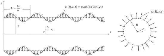
A pipe with permeable wall is considered, as depicted in Figure 1. The suction/injection is considered to be periodic, with a period of . The flow is assumed to be slow, laminar, and axisymmetric governed by the continuity and the Stokes equations, written in the cylindrical coordinate reference system. Furthermore, the fluid is assumed to be incompressible, with a constant density ρ, and Newtonian, with a constant dynamic viscosity μ. Introducing the stream function , the axial velocity and the radial velocity are defined as follows,

Figure 1.
Schematic presentation of the problem. On the left side, the longitudinal cross-section of the pipe with the permeable walls where the suction/injection is represented as a sinusoidal function of at a given , with a spatial period of . On the right side, the circumferential cross-section of the pipe with a different view of the suction/injection at a given .
Subsequently, the continuity equation is satisfied identically and the Stokes equations are written as follows,
is a second order differential operator, defined by [17],
Eliminating pressure from Equations (2) and (3), we obtain a partial differential equation with respect to [18],
The corresponding boundary conditions for the velocity components are
A constant pressure condition is assumed along the axis of the pipe,
2.2. Problem Solution
We seek the analytical solution of the above problem, using the following Ansatz for the stream function Ψ,
where .
According to the above expression, the velocity components can be written as
The and operators in Equations (2), (3) and (5) reduce to the following expressions
So, the partial differential Equation (5) of the problem reduces to the following fourth order linear ordinary differential equation
By the introduction of the dimensionless variables,
the differential Equation (12) takes the following form
and by substituting
it reduces to a linear Bessel equation of the form,
Using the variable transformation,
the differential Equation (16) takes the form of a Bessel equation,
The general solution of the above Bessel equation is [19],
, are the first-order-modified Bessel functions of the first and second kind, respectively. Substituting the expression (19) in (15), an inhomogeneous Bessel equation is derived,
The Bessel function of the second kind is rejected as it obtains infinite values at the pipe centerline, and Equation (20) reduces to,
The inhomogeneous Bessel Equation (21) has the following solution [19],
The above expression is the addition of the solution of the corresponding homogeneous equation and a partial solution of the inhomogeneous equation.
Rewriting the boundary conditions (6) for the velocity at the wall of the porous pipe in imaginary formulation,
and accordingly with respect to f,
The constants and are determined by introducing the boundary conditions (24a,b) in the solution (22),
Finally, the analytical expressions for the velocity components are,
and in dimensionless form,
where the dimensionless coordinates and parameters are defined as,
The mean dimensionless velocity over the cross-section is calculated by the integration of the axial velocity component, resulting in the following relation,
The pressure distribution is calculated by integrating Equations (2) and (3). The boundary condition and the calculated pressure distribution in dimensionless form are given by the following expressions assuming ,
where is the dimensionless pressure defined as,
Rewriting Equations (30), (31) and (35) as,
and taking into consideration the imaginary part of the relations, which correspond to the boundary conditions (6a,b), we arrive at the following relations for the velocity components and the pressure,
The obtained solution, due to the linear form of the creeping flow equations, can be straightforwardly added to the Poiseuille solution of steady flow and/or to the oscillatory flow in a circular pipe. As a limit of the present solution for very small Womersley number (), the steady state solution of Siddiqui et al. [11] can be obtained.
3. Results and Discussion
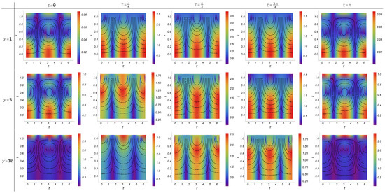
Calculations were carried out for different values of the parameters and entering the problem and the results are depicted graphically. Figure 2 presents the velocity field at various time instances for three values of the Womersley number. The periodicity of the velocity is evident both spatially and temporally. Peak values migrate towards the pipe wall with increasing oscillation frequency, while the velocity acquires a flat profile around the pipe axis. A dominant characteristic of the flow, clear in the stream density plots of Figure 2, is the recurrent recirculation zones with alternating direction every half a time period.

Figure 2.
Velocity stream density plots and velocity magnitude contours (colored) along and axes, for ε = 1, for three values of the Womersley number (γ = 1, 5, 10), at five instances within half a period (τ = 0, π/4, π/2, 3π/4, π).
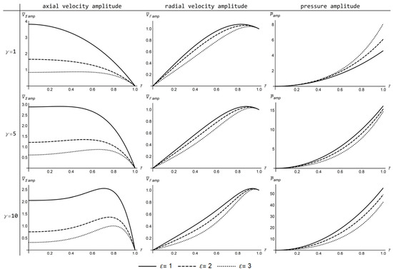
Similar observations are made in Figure 3, which depicts the amplitude profile of axial and radial velocity components, and pressure, for three different values of the Womersley parameter (γ = 1, 5, 10) and the suction/injection parameter (ε = 1, 2, 3). For small values of Womersley parameter (γ = 1) and suction injection parameter (ε = 1), the axial velocity acquires an oscillating, parabolic-like profile (quasi steady Poiseuille flow), with mean value and maximum value approaching . It can be noticed that the amplitude of the axial velocity reduces with a factor of 2/ε. For larger values of the Womersley parameter, the axial velocity profile flattens around the pipe axis, while higher values appear near the pipe wall. Such behavior is typical for oscillating pipe flows at high frequencies and is due to the boundary layer character of the flow near the pipe wall [20,21]. Regarding the radial velocity, its peak value shifts closer to the pipe wall with increasing values of the Womersley parameter.

Figure 3.
Profiles of the axial velocity, radial velocity and pressure amplitudes for different values of the Womersley number (γ = 1, 5, 10) and the suction/injection number (ε = 1, 2, 3).
The pressure amplitude is an increasing function of the Womersley parameter (Figure 3). A physical explanation of the pressure amplitude increase under increasing Womersley number lies on the balance of inertial, pressure and viscous forces dictated by the law of momentum conservation. An oscillatory flow with high frequency leads to the increase in unsteady inertial forces that is compensated mainly by the increase in pressure. It is noticeable that, for γ = 1, the pressure amplitude increases for increasing ε values, while the reverse behavior is observed for higher γ values. The reversal of the pressure amplitude profiles under increasing suction/injection parameter takes place gradually within the interval 3 < γ < 4. After that, any increase in the frequency leads to bigger differences between the pressure amplitudes for the various ε values. Physically, the latter effect is a result of high suction/injection frequency both in space and time. Τhe reversed pattern of pressure (but not of velocity), predicted by the solution, is an interesting finding that is worth further investigation.
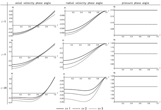
The phase angle profiles of the axial and radial velocity components, and pressure are shown in Figure 4. For small values of γ, the phase angle is close to zero, for all ε values. The phase angles of and have the same value at the axis of the pipe and different values at the pipe wall, where , according to the applied boundary condition. For large values of Womersley number γ, the phase angle near the pipe wall approaches to π/4, for all values of ε. The phase angle of pressure is constant along the axis, because the expression (42) is independent of . When γ tends to very small values, , and when γ tends to very high values, the pressure phase angle approaches a value . Overall, the phase angle is also an increasing function of the Womersley number like the pressure amplitude.

Figure 4.
Profiles of the axial velocity, radial velocity and pressure phase angles for different values of the Womersley number (γ = 1, 5, 10) and the suction/injection number (ε = 1, 2, 3).
4. Conclusions
The current study presents an analytical solution that generalizes the literature on flows driven by the suction/injection occurring at the wall of permeable circular pipes. Introducing the stream function, the momentum equation reduces to a fourth order ordinary differential equation and after several transformations, to an inhomogeneous Bessel equation that is solved analytically. Here, the suction/injection is considered to be periodic both in space and time generating an oscillatory flow with recurrent recirculation zones and points of flow separation. The increase in suction/injection temporal frequency, controlled by the Womersley number, results in the shift in peak velocity towards the permeable wall and in the increase in pressure. Concerning the spatial frequency, the increase in the suction/injection parameter leads to a decrease in velocity for all Womersley numbers. For small Womersley numbers, an increase in pressure is noticed. The combined increase in both parameters was found to be causing a reduction in both velocity and pressure. The problem description mostly fits in biofluidic systems, such as the renal tubules and the glymphatic system in the brain, where fluid exchange seems to be taking place between permeable interfaces. The mathematical model along with its analytic solution could serve as a basis for the study of the aforementioned biofluidic systems.
Author Contributions
Conceptualization, S.T.; Formal analysis, C.M. and S.T.; Investigation, C.M. and S.T.; Methodology, C.M., A.R. and S.T.; Project administration, C.M. and S.T.; Supervision, C.M. and S.T.; Validation, C.M., A.R. and S.T.; Visualization, A.R.; Writing—original draft, C.M., A.R. and S.T.; Writing—review & editing, C.M., A.R. and S.T. All authors have read and agreed to the published version of the manuscript.
Funding
This research received no external funding.
Institutional Review Board Statement
Not applicable.
Informed Consent Statement
Not applicable.
Data Availability Statement
Not applicable.
Conflicts of Interest
The authors declare no conflict of interest.
References
- Yuan, S.; Finkelstein, A. Laminar pipe flow with injection and suction through a porous wall. Trans. Am. Soc. Mech. Eng. 1956, 78, 719–724. [Google Scholar] [CrossRef]
- Terrill, R. Laminar flow in a porous tube. J. Fluids Eng. 1983, 105, 303–307. [Google Scholar] [CrossRef]
- Tsangaris, S.; Kondaxakis, D.; Vlachakis, N. Exact solution for flow in a porous pipe with unsteady wall suction and/or injection. Commun. Nonlinear Sci. Numer. Simul. 2007, 12, 1181–1189. [Google Scholar] [CrossRef]
- Chang, H.N.; Ha, J.S.; Park, J.K.; Kim, I.H.; Shin, H.D. Velocity field of pulsatile flow in a porous tube. J. Biomech. 1989, 22, 1257–1262. [Google Scholar] [CrossRef]
- Sidnawi, B.; Santhanam, S.; Wu, Q. Analytical and numerical study of a pulsatile flow in a porous tube. J. Fluids Eng. 2019, 141, 121205. [Google Scholar] [CrossRef]
- Macey, R.I. Pressure flow patterns in a cylinder with reabsorbing walls. Bull. Math. Biophys. 1963, 25, 1–9. [Google Scholar] [CrossRef]
- Macey, R.I. Hydrodynamics in the renal tubule. Bull. Math. Biophys. 1965, 27, 117–124. [Google Scholar] [CrossRef] [PubMed]
- Kelman, R. A theoretical note on exponential flow in the proximal part of the mammalian nephron. Bull. Math. Biophys. 1962, 24, 303–317. [Google Scholar] [CrossRef] [PubMed]
- Kozinski, A.; Schmidt, F.; Lightfoot, E. Velocity profiles in porous-walled ducts. Ind. Eng. Chem. 1970, 9, 502–505. [Google Scholar] [CrossRef]
- Bhatti, K.; Siddiqui, A.M.; Bano, Z. Unsteady incompressible Stokes flow through porous pipe of uniform circular cross section with periodic suction and injection. Sukkur IBA J. Comput. Math. Sci. 2017, 1, 13–21. [Google Scholar] [CrossRef][Green Version]
- Siddiqui, A.; Sohail, A.; Naqvi, S.; Haroon, T. Analysis of Stokes flow through periodic permeable tubules. Alex. Eng. J. 2017, 56, 105–113. [Google Scholar] [CrossRef][Green Version]
- Romanò, F.; Suresh, V.; Galie, P.A.; Grotberg, J.B. Peristaltic flow in the glymphatic system. Sci. Rep. 2020, 10, 21065. [Google Scholar] [CrossRef] [PubMed]
- Rasmussen, M.K.; Mestre, H.; Nedergaard, M. Fluid transport in the brain. Physiol. Rev. 2022, 102, 1025–1151. [Google Scholar] [CrossRef] [PubMed]
- Thomas, J.H. Fluid dynamics of cerebrospinal fluid flow in perivascular spaces. J. R. Soc. Interface 2019, 16, 20190572. [Google Scholar] [CrossRef] [PubMed]
- Mestre, H.; Tithof, J.; Du, T.; Song, W.; Peng, W.; Sweeney, A.M.; Olveda, G.; Thomas, J.H.; Nedergaard, M.; Kelley, D.H. Flow of cerebrospinal fluid is driven by arterial pulsations and is reduced in hypertension. Nat. Commun. 2018, 9, 4878. [Google Scholar] [CrossRef] [PubMed]
- Raptis, A.; Manopoulos, C.; Xenos, M.; Tsangaris, S. Oscillating magnetohydrodynamic Stokes flow between porous plates with spatiotemporally periodic reabsorption. Fluids 2021, 6, 156. [Google Scholar] [CrossRef]
- Panton, R.L. Incompressible Flow; John Wiley & Sons: Hoboken, NJ, USA, 2013. [Google Scholar]
- Langlois, W.E.; Deville, M.O. Slow Viscous Flow, 2nd ed.; Springer International Publishing: Berlin/Heidelberg, Germany, 2014. [Google Scholar]
- Korenev, B.G. Bessel Functions and Their Applications; CRC Press: Boca Raton, FL, USA, 2002. [Google Scholar]
- Womersley, J.R. Method for the calculation of velocity, rate of flow and viscous drag in arteries when the pressure gradient is known. J. Physiol. 1955, 127, 553–563. [Google Scholar] [CrossRef] [PubMed]
- Richardson, E.; Tyler, E. The transverse velocity gradient near the mouths of pipes in which an alternating or continuous flow of air is established. Proc. Phys. Soc. 1929, 42, 1. [Google Scholar] [CrossRef] [PubMed]
Publisher’s Note: MDPI stays neutral with regard to jurisdictional claims in published maps and institutional affiliations. |
© 2022 by the authors. Licensee MDPI, Basel, Switzerland. This article is an open access article distributed under the terms and conditions of the Creative Commons Attribution (CC BY) license (https://creativecommons.org/licenses/by/4.0/).