Selection Criteria for Biplane Wing Geometries by Means of 2D Wind Tunnel Tests
Abstract
1. Introduction
2. Materials and Methods
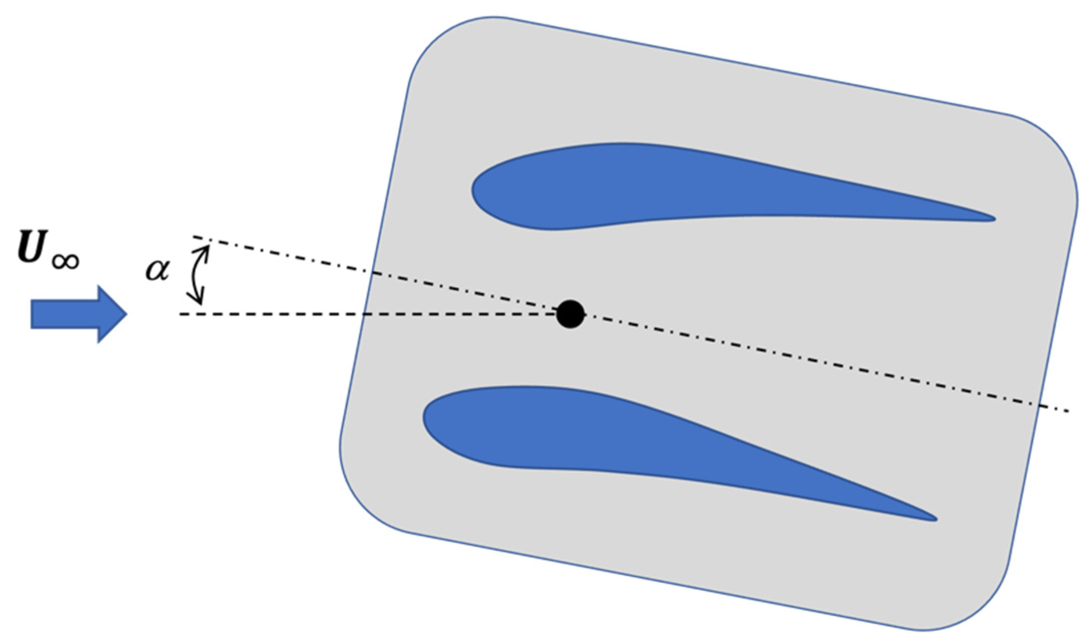
2.1. Prototypes Description
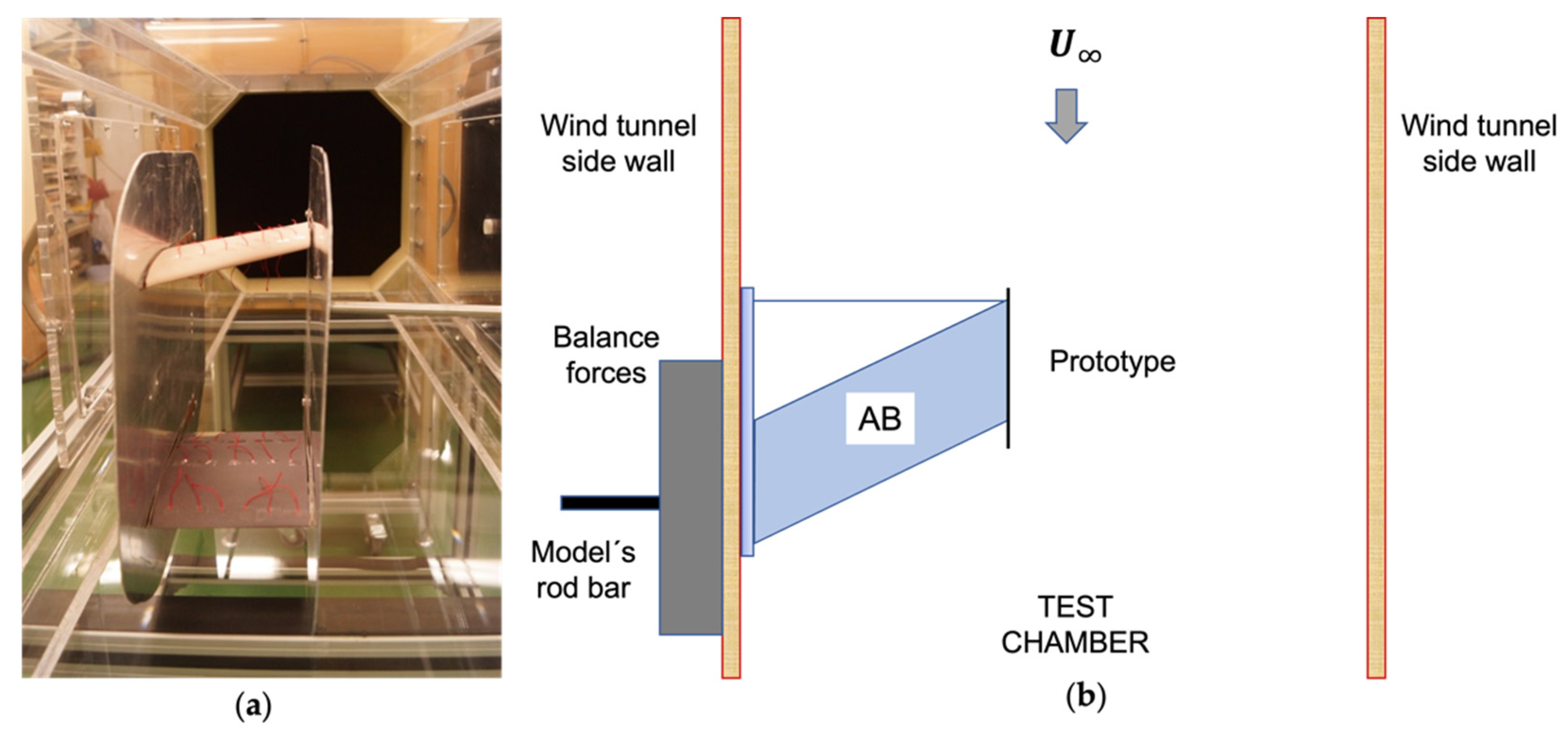
2.2. Wind Tunnel Facility
2.3. The Two–Dimensional Flow Hypothesis
2.4. Experimental Test Procedure
3. Results
4. Discussion
5. Conclusions
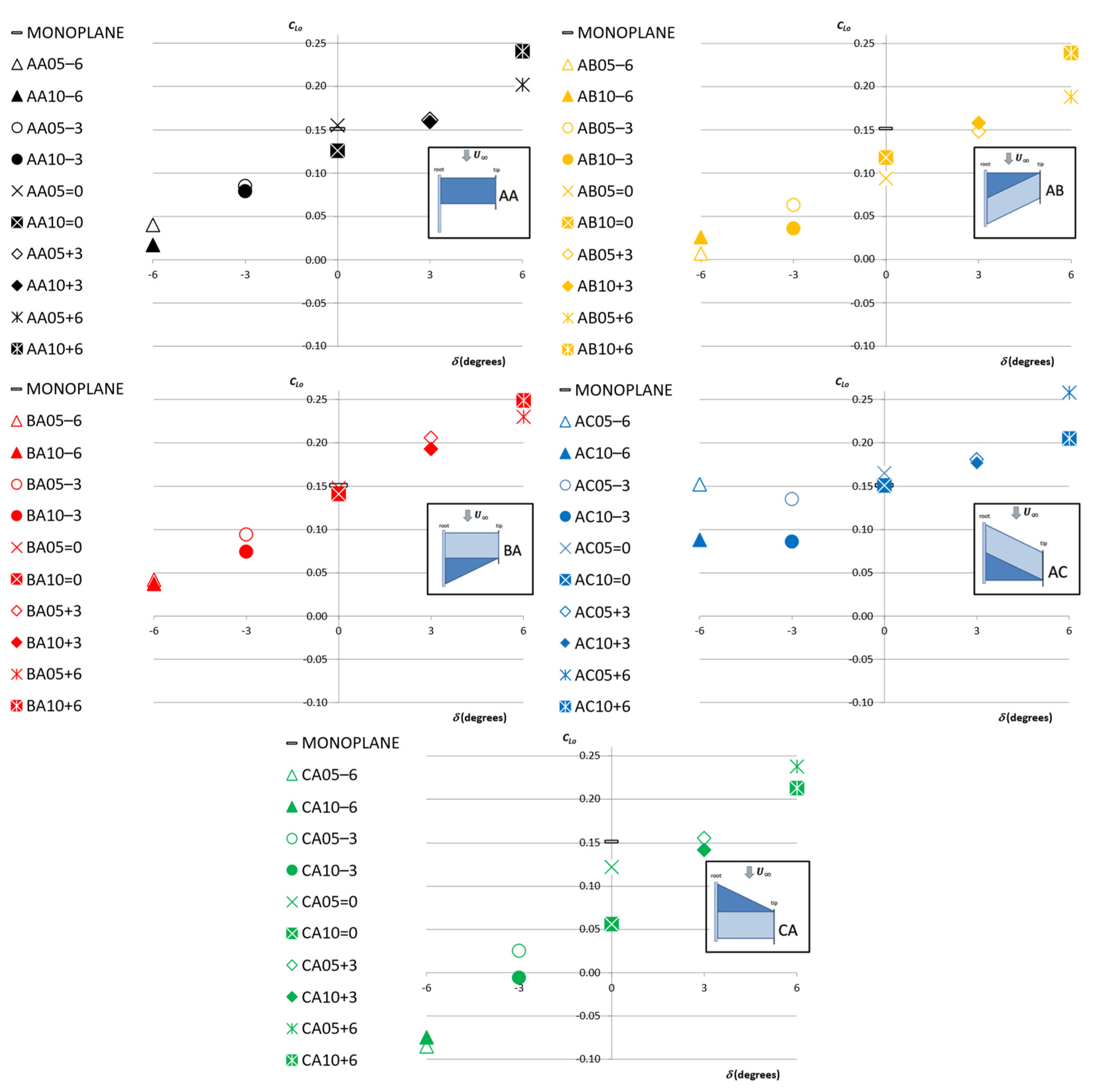
- increases with G.
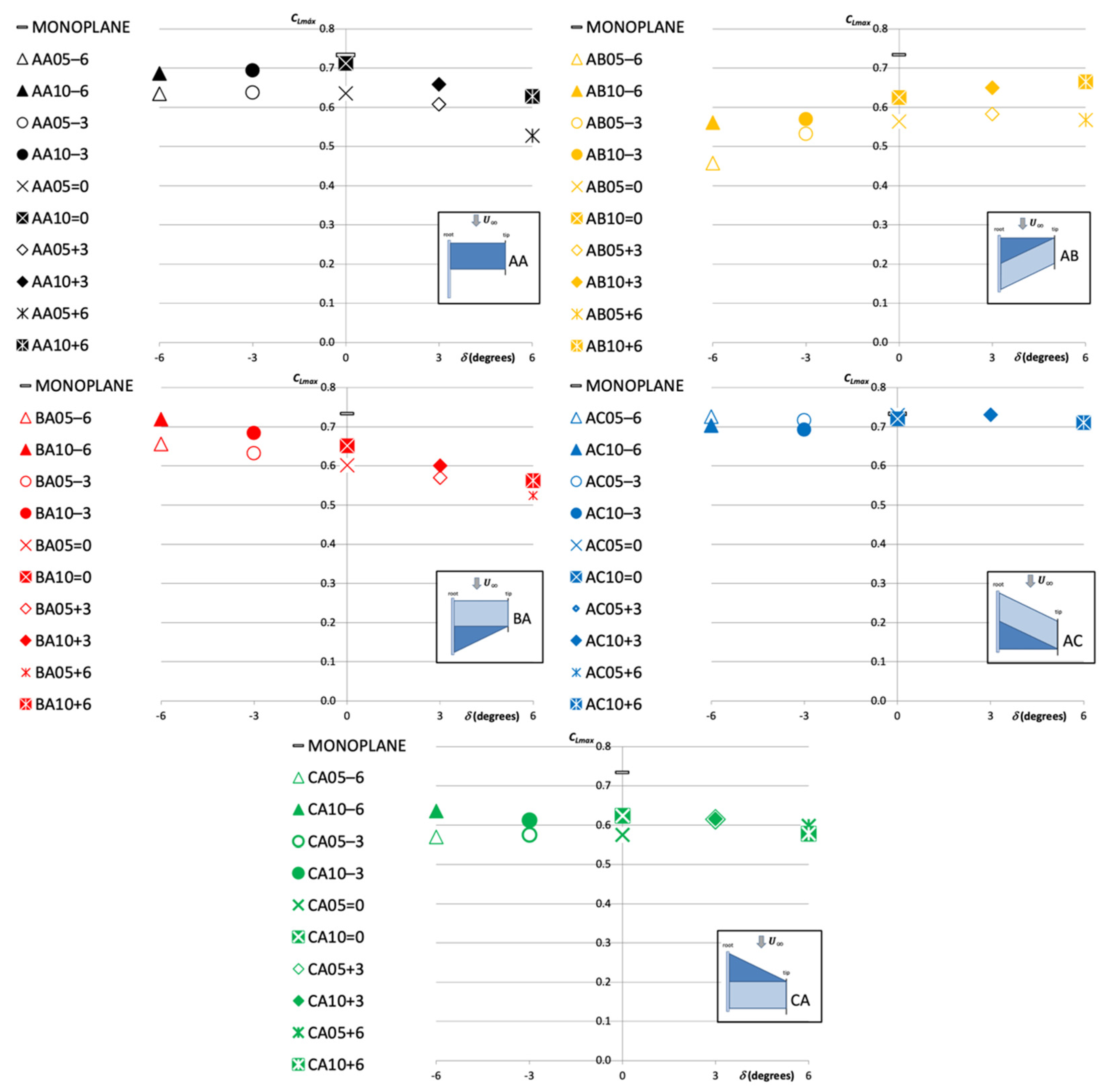
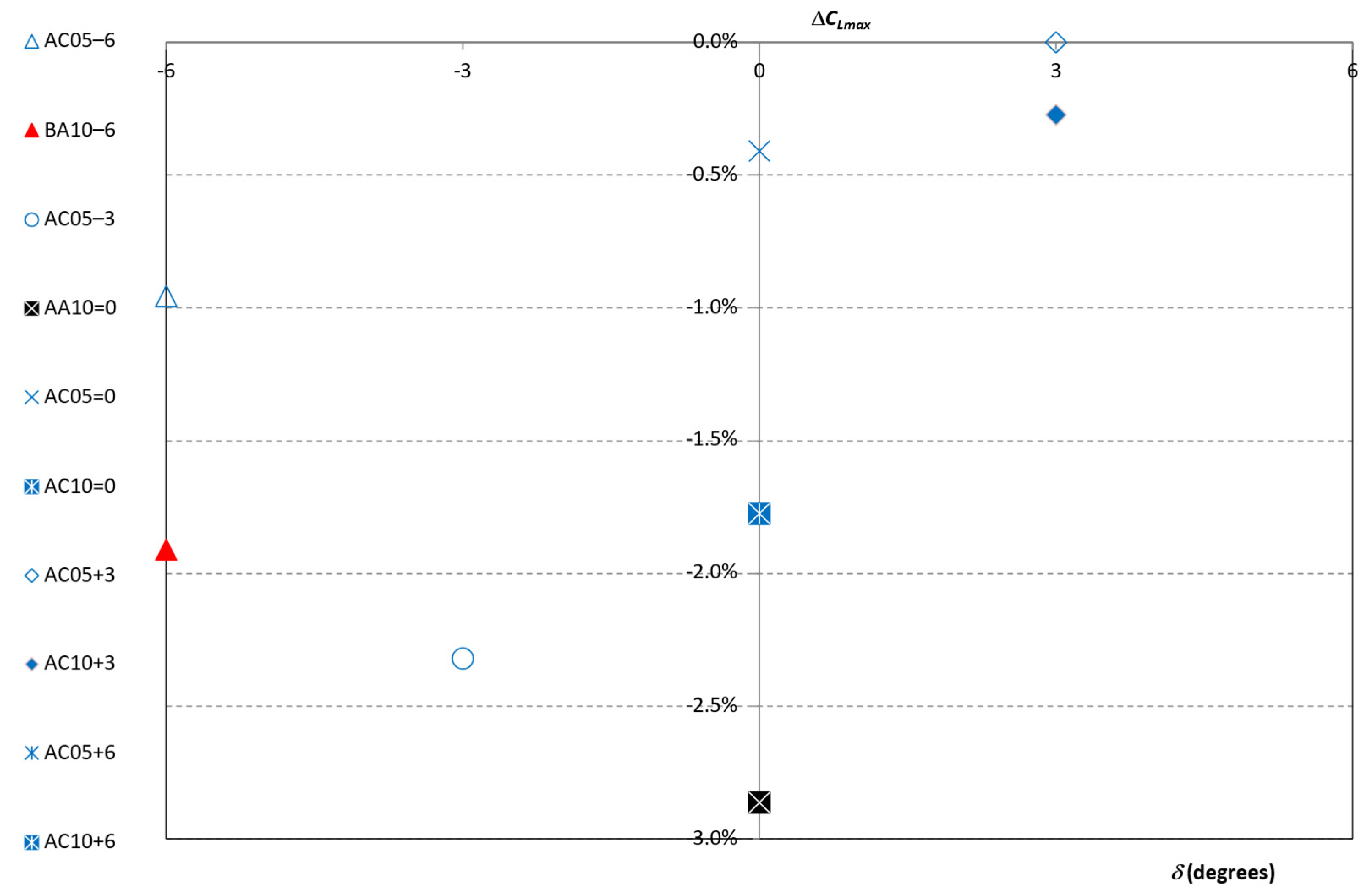
- For those wing configurations where , there is a relationship between and that depends on the wing configuration. For those configurations where , decreases asincreases. On the contrary, for the wing configuration where , the increases asincreases.
- For those wing configurations where the wing’s swept angle was , seems to remain constant with .
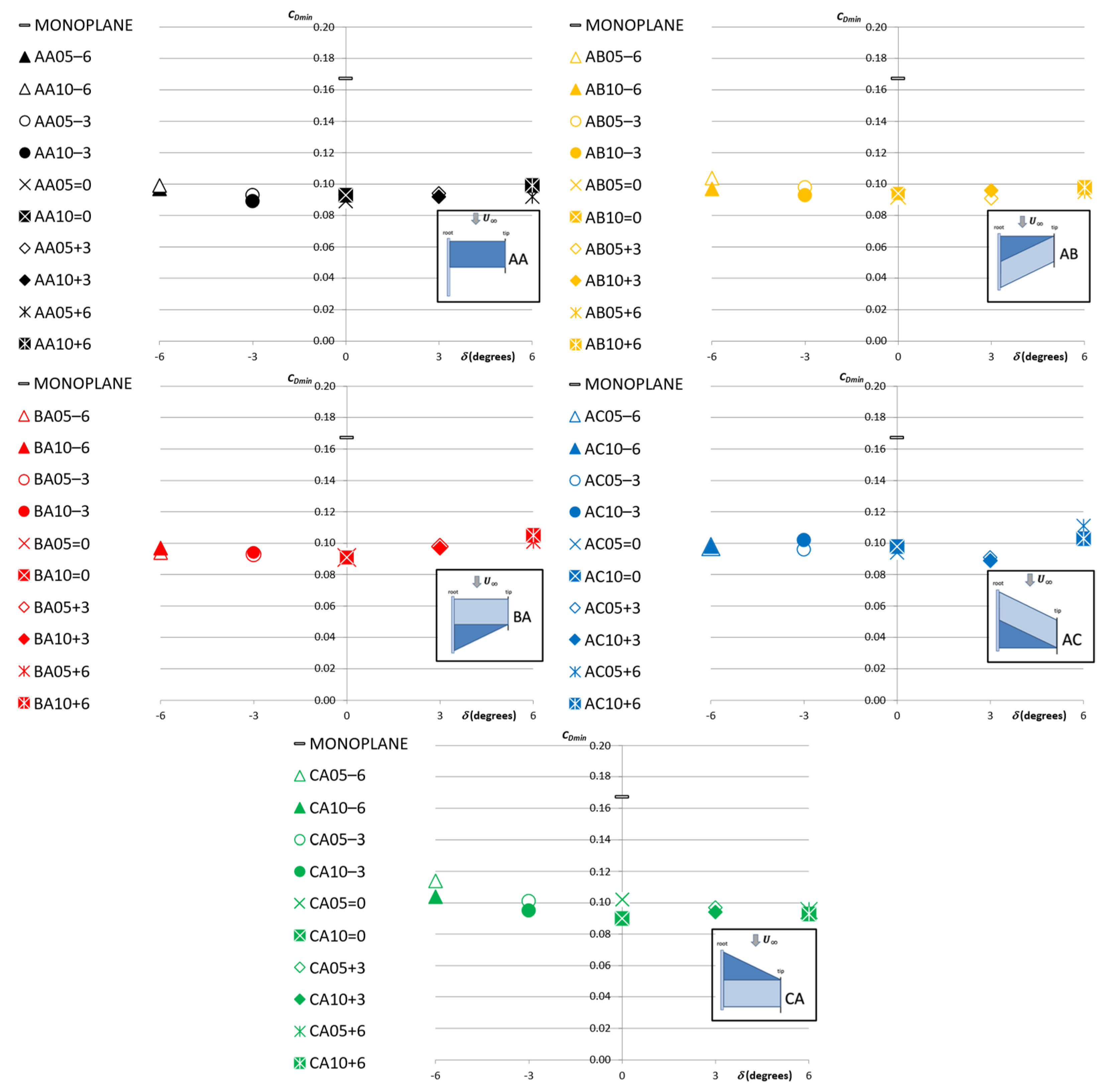
- seems to remain nearly constant.
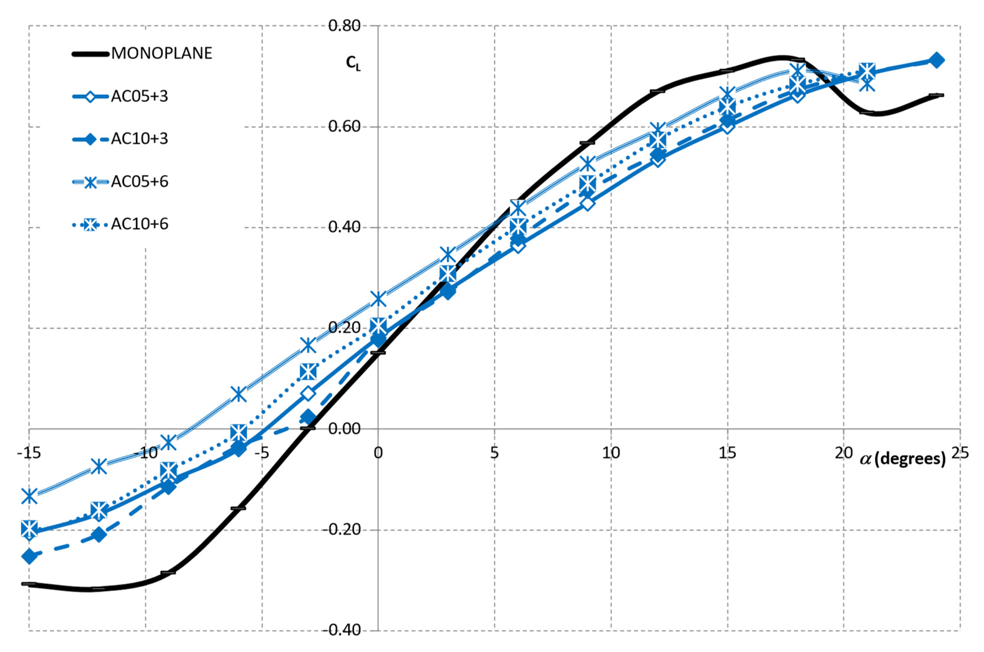
- A linear relationship between the and is evidenced for most of the cases. For those wing configurations where s < 0, the increase in seems to be greater. However, the overall higher values of are observed for those wing configurations with .
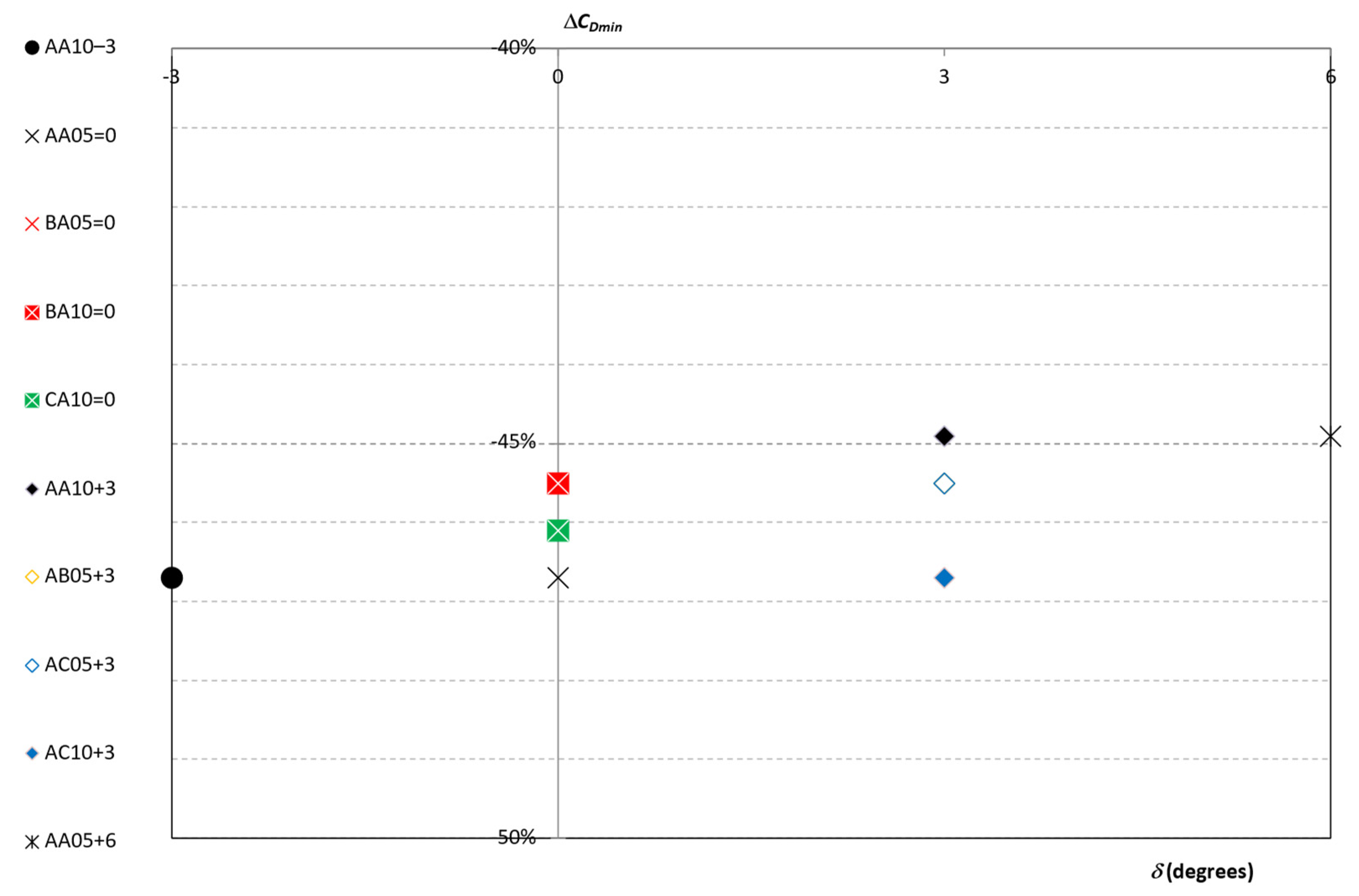
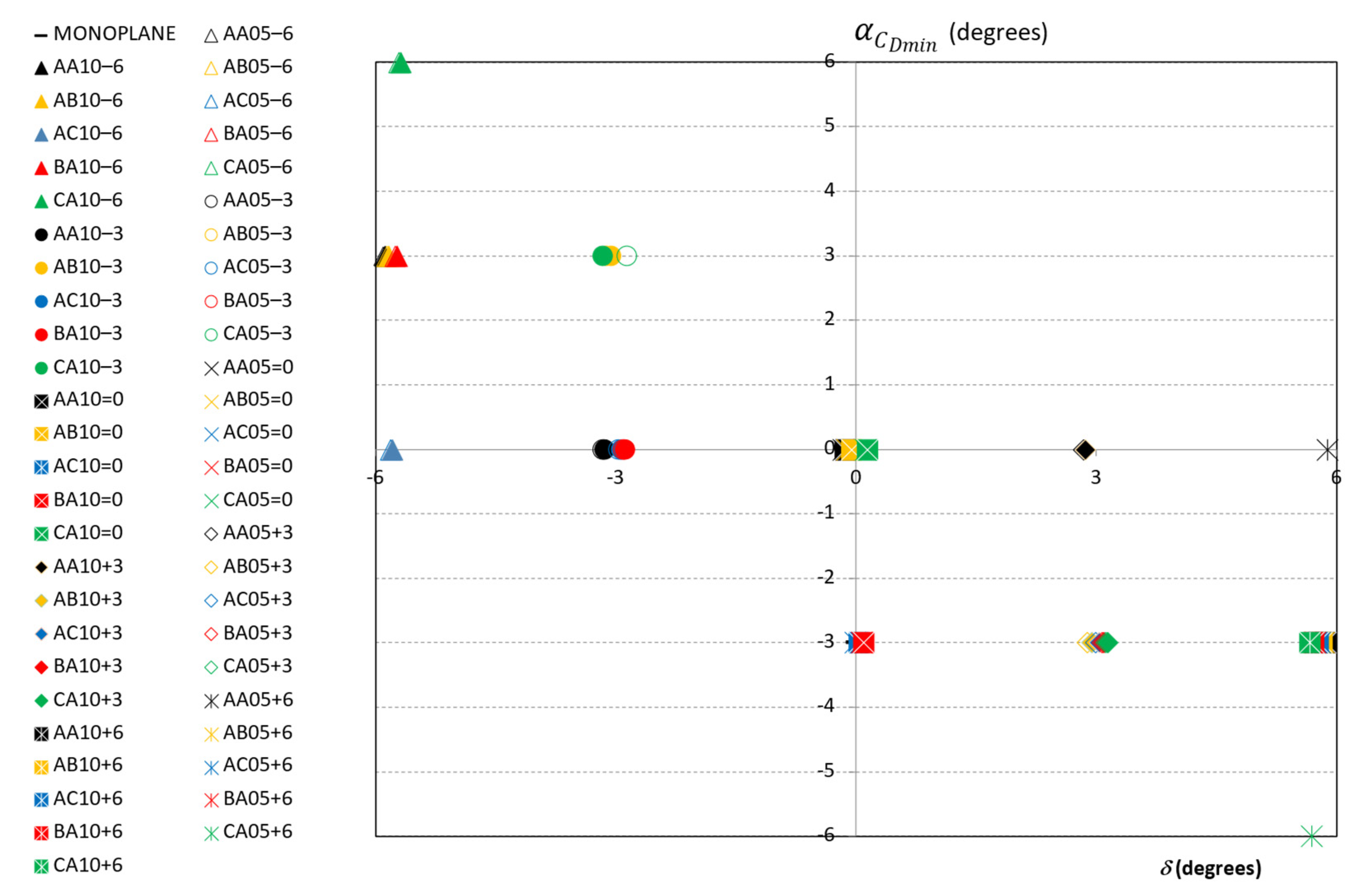
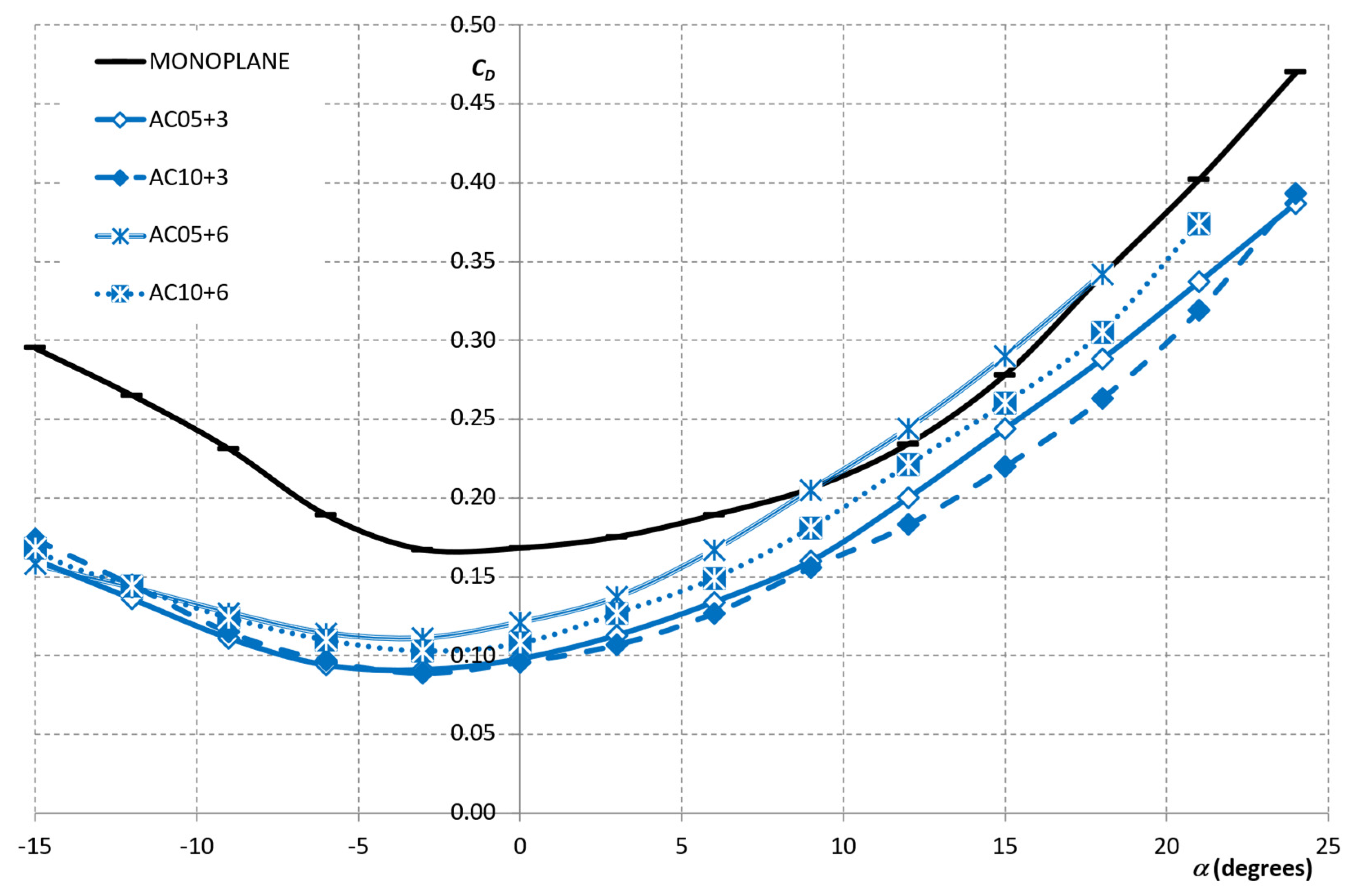
- The minimum value of are usually obtained for .
- As increases, the value of decreases.
Author Contributions
Funding
Institutional Review Board Statement
Informed Consent Statement
Data Availability Statement
Conflicts of Interest
Abbreviations
| The following abbreviations are used in this manuscript: | |
| MAV | Micro Air Vehicles |
| PIV | Particle Image Velocimetry |
| RMS | Root mean square |
| RPAS | Remotely Piloted Aircraft System |
| UAV | Unmanned Air Vehicle |
| The following nomenclature is used in this manuscript: | |
| AR | |
| b | Wingspan |
| c | Wing chord length |
| CL | |
| Lift slope coefficient | |
| CLo | Lift coefficient for zero angle of attack |
| CLmax | Maximum lift coefficient |
| CD | |
| CDO | Parasitic drag coefficient |
| CDi | Induced drag coefficient; drag due to lift |
| CDmin | Minimum profile drag coefficient |
| CL/CD | Lift–to–drag ratio |
| D | Drag |
| Induced drag | |
| Parasitic drag | |
| Drag due to lift | |
| E | Endurance. The time that an aircraft can fly between takeoff and landing based on several flight conditions. |
| Emax | Maximum endurance |
| G | Gap |
| Iu | . |
| L | Lift |
| R | Range. Distance an aircraft can fly between takeoff and landing based on several flight conditions. |
| Rmax | Maximum range |
| Re | |
| S | Wing gross area |
| s | Stagger |
| Mean value of air speed | |
| Umax | Maximum value of air speed on wind tunnel test section |
| Umin | Minimum value of air speed on wind tunnel test section |
| Freestream velocity | |
| xmax | Maximum horizontal distance in gliding flight. Distance that an aircraft can glide in a gliding flight based on several flight conditions. |
| W | Weight |
| Angle of attack | |
| Angle of attack for the minimum drag coefficient | |
| Increment in the profile drag coefficient due to lift | |
| Angle of incidence of each profile | |
| Air density | |
| Dynamic viscosity of air | |
| Standard deviation of U | |
| Sweep angle | |
References
- Munk, M.M. The Minimum Induced Drag of Airfoils; NACA TR 121; US Government Printing Office: Washington, DC, USA, 1923. [Google Scholar]
- Prandtl, L. Induced Drag of Multiplanes; NACA TN 182; US Government Printing Office: Washington, DC, USA, 1924. [Google Scholar]
- Jemitola, P.O.; Fielding, J.P. Box Wing Aircraft Conceptual Design. In Proceedings of the 28th Congress of the International Council of the Aeronautical Sciences, Brisbane, Australia, 23–28 September 2012; pp. 1–10. Available online: http://www.icas.org/ICAS_ARCHIVE/ICAS2012/PAPERS/213.PDF (accessed on 7 March 2022).
- Jemitola, P.O.; Monterzino, G.; Fielding, J. Wing mass estimation algorithm for medium range box wing aircraft. Aeronaut. J. 2013, 117, 329–340. [Google Scholar] [CrossRef]
- Kroo, I. Nonplanar wing concepts for increased aircraft efficiency. VKI Lect. Ser. Innov. Config. Adv. Concepts Futur. Civ. Aircr. 2005, 1, 6–10. [Google Scholar]
- Khan, F.; Krammer, P.; Scholz, D. Preliminary Aerodynamic Investigation of Box–Wing Configurations Using Low Fidelity Codes. Dtsch. Luft– und Raumfahrtkongress Doc. 2010, 161308, 313–327. [Google Scholar]
- Barcala Montejano, M.A.; Cuerno Rejado, C.; Gandia Agüera, F.; Rodriguez Sevillano, A.; Del Giudice, S. Experimental investigation on box–wing configuration for UAS. In Proceedings of the Unmanned Air Vehicle Systems, Bristol, UK, 11–12 April 2011. [Google Scholar]
- Wolkovitch, J. The joined wing–An overview. J. Aircr. 1986, 23, 161–178. [Google Scholar] [CrossRef]
- Gall, P.D.; Smith, H.C. Aerodynamic characteristics of biplanes with winglets. J. Aircr. 1987, 24, 518–522. [Google Scholar] [CrossRef]
- Kroo, I. Drag due to lift: Concepts for prediction and reduction. Annu. Rev. Fluid Mech. 2001, 33, 587–617. [Google Scholar] [CrossRef]
- Kroo, I. Innovations in aeronautics. In Proceedings of the 42nd AIAA Aerospace Sciences Meeting and Exhibit, Reno, NV, USA, 5–8 January 2004; p. 1. [Google Scholar]
- Torenbeek, E. Blended–wing–body and all wing airliners. In Proceedings of the 8th European Workshop on Aircraft Design Education, Samara, Russia, 29 May–2 June 2007. [Google Scholar]
- Abbas, A.; de Vicente, J.; Valero, E. Aerodynamic technologies to improve aircraft performance. Aerosp. Sci. Technol. 2013, 28, 100–132. [Google Scholar] [CrossRef]
- Moschetta, J.-M.; Thipyopas, C. Optimization of a biplane micro air vehicle. In Proceedings of the 23rd AIAA Applied Aerodynamics Conference, Toronto, ON, Canada, 6–9 June 2005; p. 4613. [Google Scholar]
- Shkarayev, S.V.; Ifju, P.G.; Kellogg, J.C.; Mueller, T.J. Introduction to the Design of Fixed–Wing Micro Air Vehicles Including Three Case Studies; American Institute of Aeronautics and Astronautics: Reston, VA, USA, 2007. [Google Scholar]
- Reg, A. Unmanned Aircraft Systems: UAVS Design, Development and Deployment; John Wiley & Sons: Hoboken, NJ, USA, 2011. [Google Scholar]
- Thipyopas, C.; Moschetta, J.-M. A fixed–wing biplane MAV for low speed missions. Int. J. Micro Air Veh. 2009, 1, 13–33. [Google Scholar] [CrossRef]
- Phillips, P.; Hrishikeshavan, V.; Rand, O.; Chopra, I. Design and development of a scaled quadrotor biplane with variable pitch proprotors for rapid payload delivery. In Proceedings of the American Helicopter Society 72nd Annual Forum, West Palm Beach, FL, USA, 17–19 May 2016; pp. 17–19. [Google Scholar]
- Ryseck, P.; Yeo, D.; Hrishikeshavan, V.; Chopra, I. Aerodynamic and mechanical design of a morphing winglet for a quadrotor biplane tail–sitter. In Proceedings of the Vertical Flight Society 8th Autonomous VTOL Symposium, virtual, 26–28 January 2019; pp. 29–31. [Google Scholar]
- Bogdanowicz, C.; Hrishikeshavan, V.; Chopra, I. Development of a quad–rotor biplane MAV with enhanced roll control authority in fixed wing mode. In Proceedings of the American Helicopter Society, 71st Annual Forum, Virginia Beach, VA, USA, 5–7 May 2015. [Google Scholar]
- Strom, E. Performance and Sizing Tool for Quadrotor Biplane Tailsitter UAS. Ph.D. Thesis, University of Maryland, College Park, MD, USA, 2017. [Google Scholar]
- Deng, S.; Xiao, T.; van Oudheusden, B.; Bijl, H. Numerical investigation on the propulsive performance of biplane counter–flapping wings. Int. J. Micro Air Veh. 2015, 7, 431–439. [Google Scholar] [CrossRef]
- McMasters, J.H.; Kroo, I.M. Advanced configurations for very large transport airplanes. Aircr. Des. 1998, 1, 217–242. [Google Scholar] [CrossRef]
- Moschetta, J.-M.; Thipyopas, C. Aerodynamic Performance of a Biplane Micro Air Vehicle. J. Aircr. 2007, 44, 291–299. [Google Scholar] [CrossRef]
- Maqsood, A.; Hiong, T. Go Parametric studies and performance analysis of a biplane micro air vehicle. Int. J. Aeronaut. Space Sci. 2013, 14, 229–236. [Google Scholar] [CrossRef][Green Version]
- Spedding, G.R.; McArthur, J. Span Efficiencies of Wings at Low Reynolds Numbers. J. Aircr. 2010, 47, 120–128. [Google Scholar] [CrossRef]
- Montejano, M.A.B.; Sevillano, A.R.; Rojo, M.E.R.; Morales–Serrano, S. A wind tunnel two–dimensional parametric investigation of biplane configurations. J. Mech. Eng. Autom. 2014, 4, 412–421. Available online: http://oa.upm.es/34874/ (accessed on 7 March 2022).
- Frediani, A. The Prandtl Wing. VKI Lect. Ser. Innov. Config. Adv. Concepts Futur. Civ. Aircr. 2005, 1–23. [Google Scholar]
- Frediani, A.; Gasperini, M.; Saporito, G.; Rimondi, A. Development of a Prandtl Plane aircraft configuration. Proc. Inst. Mech. Eng. Part I J. Syst. Control. Eng. 2003, 222, 2263–2276. [Google Scholar]
- Luciano, D.; Antonio, D.; Giovanni, M.; Rauno, C. An Invariant Formulation for the Minimum Induced Drag Conditions of Non–planar Wing Systems. In Proceedings of the 52nd Aerospace Sciences Meeting, National Harbor, ML, USA, 13–17 January 2014; pp. 13–17. [Google Scholar]
- Pelletier, A.; Mueller, T.J. Low Reynolds number aerodynamics of low–aspect–ratio, thin/flat/cambered–plate wings. J. Aircr. 2000, 37, 825–832. [Google Scholar] [CrossRef]
- Jones, R.; Cleaver, D.J.; Gursul, I. Aerodynamics of biplane and tandem wings at low Reynolds numbers. Exp. Fluids 2015, 56, 1047–1062. [Google Scholar] [CrossRef]
- Selig, M.S.; Guglielmo, J.J. High–lift low Reynolds number airfoil design. J. Aircr. 1997, 34, 72–79. [Google Scholar] [CrossRef]
- Owen, F.K.; Owen, A.K. Measurement and assessment of wind tunnel flow quality. Prog. Aerosp. Sci. 2008, 44, 315–348. [Google Scholar] [CrossRef]
- Mueller, T.J.; DeLaurier, J.D. Aerodynamics of small vehicles. Annu. Rev. Fluid Mech. 2003, 35, 89–111. [Google Scholar] [CrossRef]
- Mueller, T.J. On the birth of micro air vehicles. Int. J. Micro Air Veh. 2009, 1, 1–12. [Google Scholar] [CrossRef]
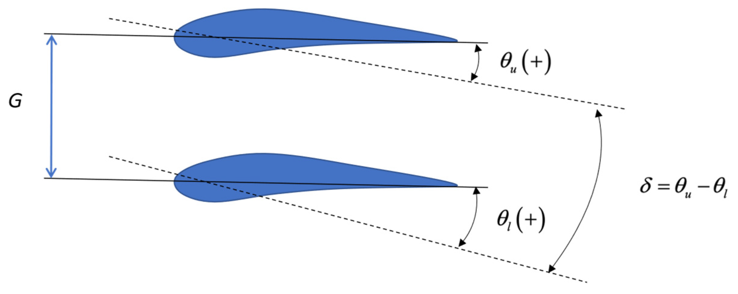

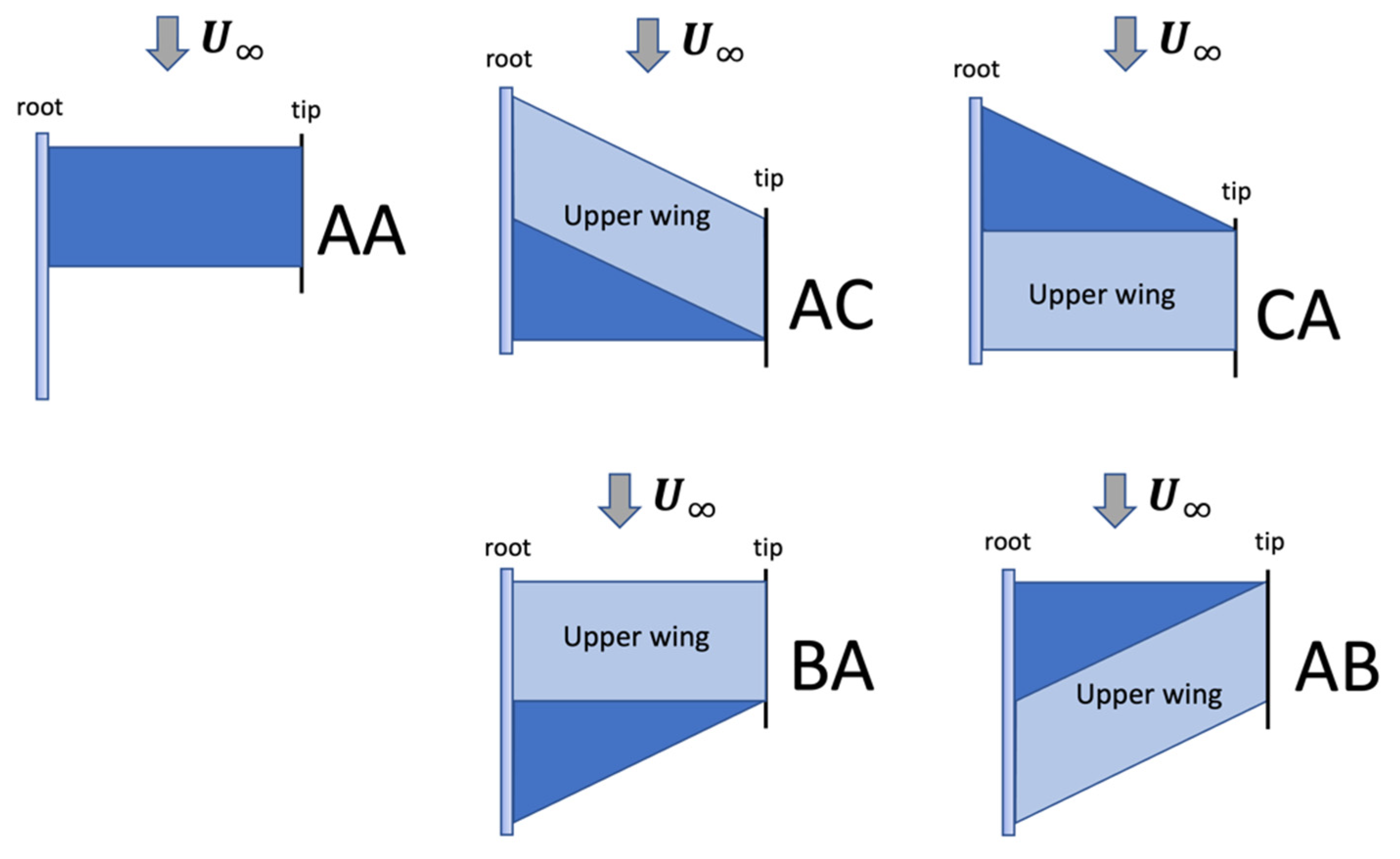

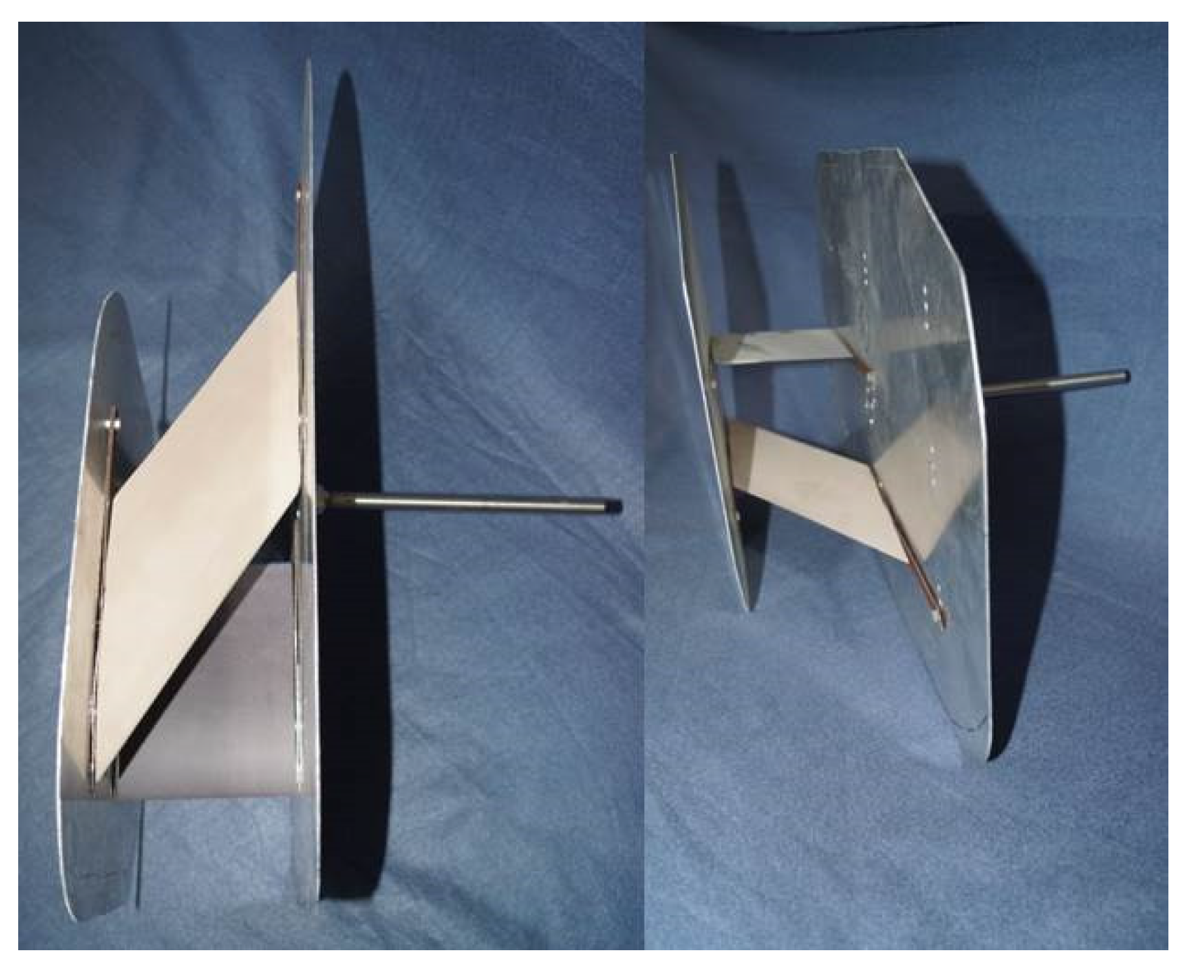
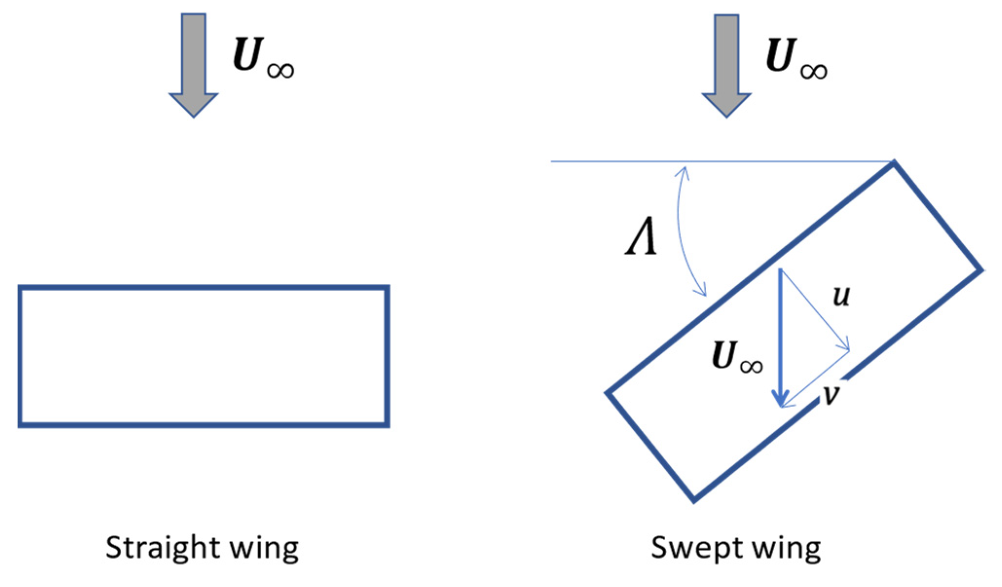




| Parameters | Values |
|---|---|
| Wing profile | Eppler E387 |
| Wing chord (c) | 160 mm |
| Wingspan (b) | 120 mm |
| Gap (G) | c/2, c |
| Incidence of upper & lower wings (,) | ±3, 0 |
| Decalage (δ) | ±6, ±3, 0 |
| Stagger (s) | 0, ±160 mm |
| Sweep angle (Λ) | 0, ±50° |
| Wing configurations (explained below) | AA, AB, AC, BA, CA |
| Characteristics | Description |
|---|---|
| Speed range | 0–30 m/s |
| Nozzle contraction ratio | 9:1 |
| Test section | Square geometry 0.45 × 0.45 × 1 (m) |
| Power unit | Fan driven by DC Electric Motor 23 kW |
| <1% | |
| Mean turbulence level Iu | <0.5% |
| Maximum Reynolds Number |
| Characteristics | Description |
|---|---|
| Position | Side wall of the test chamber |
| Degrees of freedom | Three: Lift, Drag, and Pitching Moment |
| Load cells range | Lift: 100 N Drag: 50 N Moment: 3.1 Nm |
| Accuracy | Lift: 0.015 N Drag: 0.0076 N Moment: Nm |
| Repeatability (RMS) | Lift: 0.004 Drag: 0.002 Moment: 0.001 |
| AA05–6 | AA10–6 | AB05–6 | AB10–6 | AC05–6 | AC10–6 | BA05–6 | BA10–6 | CA05–6 | CA10–6 | AA05–6 | AA10–6 |
| 0.032 | 0.036 | 0.032 | 0.034 | 0.032 | 0.032 | 0.032 | 0.033 | 0.031 | 0.031 | 0.032 | 0.036 |
| AA05–3 | AA10–3 | AB05–3 | AB10–3 | AC05–3 | AC10–3 | BA05–3 | BA10–3 | CA05–3 | CA10–3 | AA05–3 | AA10–3 |
| 0.033 | 0.037 | 0.035 | 0.034 | 0.031 | 0.033 | 0.032 | 0.034 | 0.034 | 0.032 | 0.033 | 0.037 |
| AA05=0 | AA10=0 | AB05=0 | AB10=0 | AC05=0 | AC10=0 | BA05=0 | BA10=0 | CA05=0 | CA10=0 | AA05=0 | AA10=0 |
| 0.032 | 0.036 | 0.035 | 0.034 | 0.032 | 0.034 | 0.031 | 0.034 | 0.031 | 0.033 | 0.032 | 0.036 |
| AA05+3 | AA10+3 | AB05+3 | AB10+3 | AC05+3 | AC10+3 | BA05+3 | BA10+3 | CA05+3 | CA10+3 | AA05+3 | AA10+3 |
| 0.027 | 0.034 | 0.034 | 0.035 | 0.034 | 0.033 | 0.031 | 0.032 | 0.030 | 0.032 | 0.027 | 0.034 |
| AA05+6 | AA10+6 | AB05+6 | AB10+6 | AC05+6 | AC10+6 | BA05+6 | BA10+6 | CA05+6 | CA10+6 | AA05+6 | AA10+6 |
| 0.026 | 0.033 | 0.032 | 0.034 | 0.031 | 0.031 | 0.031 | 0.032 | 0.032 | 0.033 | 0.026 | 0.033 |
| AA05–6 | AA10–6 | AB05–6 | AB10–6 | AC05–6 | AC10–6 | BA05–6 | BA10–6 | CA05–6 | CA10–6 | AA05–6 | AA10–6 |
| 0.032 | 0.036 | 0.032 | 0.034 | 0.032 | 0.032 | 0.032 | 0.033 | 0.031 | 0.031 | 0.032 | 0.036 |
| Case | Test Conditions | Design Criteria | Flight Conditions | Conclusions | ||
|---|---|---|---|---|---|---|
| 1 | ||||||
| 2 |
Publisher’s Note: MDPI stays neutral with regard to jurisdictional claims in published maps and institutional affiliations. |
© 2022 by the authors. Licensee MDPI, Basel, Switzerland. This article is an open access article distributed under the terms and conditions of the Creative Commons Attribution (CC BY) license (https://creativecommons.org/licenses/by/4.0/).
Share and Cite
Rodríguez-Sevillano, Á.A.; Barcala-Montejano, M.Á.; Bardera-Mora, R.; García-Magariño García, A.; Rodríguez-Rojo, M.E.; Morales-Serrano, S.; Fernández-Antón, J. Selection Criteria for Biplane Wing Geometries by Means of 2D Wind Tunnel Tests. Appl. Mech. 2022, 3, 628-648. https://doi.org/10.3390/applmech3020037
Rodríguez-Sevillano ÁA, Barcala-Montejano MÁ, Bardera-Mora R, García-Magariño García A, Rodríguez-Rojo ME, Morales-Serrano S, Fernández-Antón J. Selection Criteria for Biplane Wing Geometries by Means of 2D Wind Tunnel Tests. Applied Mechanics. 2022; 3(2):628-648. https://doi.org/10.3390/applmech3020037
Chicago/Turabian StyleRodríguez-Sevillano, Ángel Antonio, Miguel Ángel Barcala-Montejano, Rafael Bardera-Mora, Adelaida García-Magariño García, María Elena Rodríguez-Rojo, Sara Morales-Serrano, and Jaime Fernández-Antón. 2022. "Selection Criteria for Biplane Wing Geometries by Means of 2D Wind Tunnel Tests" Applied Mechanics 3, no. 2: 628-648. https://doi.org/10.3390/applmech3020037
APA StyleRodríguez-Sevillano, Á. A., Barcala-Montejano, M. Á., Bardera-Mora, R., García-Magariño García, A., Rodríguez-Rojo, M. E., Morales-Serrano, S., & Fernández-Antón, J. (2022). Selection Criteria for Biplane Wing Geometries by Means of 2D Wind Tunnel Tests. Applied Mechanics, 3(2), 628-648. https://doi.org/10.3390/applmech3020037


