Abstract
Circular and spherical particle models are a class of discrete elements (DEM) that have been increasingly applied to fracture studies of quasi-brittle materials, such as rock and concrete, due to their proven ability to simulate fracture processes through random particle assemblies representing quasi-brittle materials at the grain scale. More recently, DEM models have been applied to old stone masonry fracture studies. In order to extend its applicability to structures of larger dimensions, an enhanced hybrid particle model is proposed here that allows finite elements with a given surface roughness, provided by the discretization of the element boundary with particles, to interact with the particulate media in which they are embedded. The performance of the hybrid model is compared with that of a traditional all-particle model under uniaxial testing. It is shown that similar results are obtained, namely, in the elastic phase, figures of rupture and pre-peak and post-peak behavior, while the hybrid model allows for a significant computational run time reduction of 20% to 25% in the coarse particle assemblies. Finally, the proposed hybrid model is applied in the simulation of shear tests of stone masonry walls and dry and mortared joints, providing reasonably good agreement with both the experimental results and predictions. For the rubble masonry tests, the hybrid model allows for a computation run time reduction of around 40% when compared with an all-particle model.
1. Introduction
In the past, stone masonry was a common structural material, and many buildings with architectural and historical value are the objects of studies for their preservation. In order to assess the present condition of these historical structures, a better understanding of their complex structural behavior is required. For buildings in seismic areas, the response to cyclic loads remains a critical issue. The identification of the main parameters that influence the structural capacity will allow for the development of appropriate solutions for conservation and possible reinforcement.
The safety assessment of old stone masonry walls has promoted the development of numerical models capable of representing their complex structural behavior under both axial and transverse loadings. Two fundamental numerical approaches towards masonry analysis are possible: the micro-modelling of the individual components and the macro-modelling as a homogeneous medium [1].
Discontinuum or micro-models, where the joints and the units are explicitly modelled, have been developed using different numerical techniques: finite elements [2]; discrete elements, [3,4]; limit analysis [5]; discontinuous deformation analysis [6]; finite/discrete element for dry walls [7,8] and unreinforced masonry [9] or other rigid element models [10]. All these involve polygonal or polyhedral units.
Discrete element models with circular particles were used to simulate the granular fill of masonry bridges [11,12] and old stone masonry [13]. Recently, multi-level finite element modelling has also been applied to masonry, where the macro-model is constructed through the analysis at the micro-level of a representative volume element (RVE) and the adoption of homogenization techniques [14].
In this work, a micro-modelling approach based on the discrete element method is adopted to study old stone masonry, due to their proven ability to simulate fracture processes through random particle assemblies representing quasi-brittle materials at the grain scale [13,15,16,17,18,19]. A similar micro-model approach based on the finite element method was proposed in [20]. In this approach, both the stone units and the mortar are modelled through particles systems, the final structure formed by a system of particles, which have different properties according to the material they represent and interact through the contact interfaces [13]. Particle models based on DEM are known to be computationally demanding due to the refined discretization that they require. In order to extend their applicability to structures of larger dimensions or to adopt more refined particle models, hybrid models have been proposed that couple a DEM particle discretization in the fracture zone with finite elements (FEM) in the linear elastic region [15].
In this work, and in order to reduce the computational effort, a hybrid particle model is proposed where the stone units that are expected to remain in the elastic range are discretized by finite elements and only the particles at the stone boundary are kept, maintaining the initial stone surface roughness. In this way, the contact interaction is made independent of the finite element mesh, and only simplified particle/particle or particle/edge interactions are necessary. The proposed hybrid model has some similarities with the pinball method [21], but in this work, the particle discretization is not associated with the element but with its boundary, and instead of a hierarchical sub-division, one adopts the refined particle discretization from the start of the simulation. By having the capacity to further refine the boundary, one can have a better description of the stress distribution along the finite element edges when compared to contact models which only allow for point/edge interactions, keeping the simplicity of the latter for large displacements when compared with the more sophisticated edge/edge type of contacts [3,4]. Several three-dimensional (3D) particle models have been proposed [16,17,18,19], but it is important to note that the 2D models are still competitive when applied to more complex geometries because the equivalent 3D models would require an excessive number of particles. Even if the fracture process is a 3D process, a 2D model remains an indispensable research tool, giving information that can be used in further understanding the structural behavior, safety assessment and the evaluation of reinforcement solutions. Further, the proposed model can be easily implemented in 3D.
The hybrid particle model proposed herein enhances the available capabilities for detailed analysis of traditional constructions of irregular or rubble masonry involving rough dry or mortared joints. The core principles of the particle model are briefly presented, followed by the description of the hybrid model in which the stone units have their interior discretized with finite elements while their boundary is represented by particles. The hybrid model is first applied in the analysis of uniaxial tensile and compression tests in order to verify that it leads to the same results of an all-particle model, namely, in the elastic phase, figures of rupture and pre-peak and post-peak behavior, while requiring less computer time.
The capacity of the particle model to analyze stone masonry structures is assessed in comparison with the experimental results of monotonic shear tests of dry masonry wall under different vertical loads [22] which have been numerically studied using a finite element model, with a good match of the monotonic behavior [23]. Finally, the capabilities of the proposed hybrid model are compared with the all-particle model predictions for rubble masonry analysis for uniaxial compression tests and for shear tests with an initial pre-compression axial force. These rubble wall panels have been experimentally studied for cyclic shear loading with an initial pre-compression load [22].
2. Hybrid Particle Model
2.1. Fundamentals
In the DEM, the domain is replaced by an assembly of discrete entities that interact with each other through contact points or contact interfaces. The ability to include finite displacements and rotations, including complete detachment, and to recognize new contacts as the calculation progresses are essential features. The forces acting on each entity are related to the relative displacements of each entity with respect to its neighbors (contacts) and to the entity deformation given its loads. At each step, given the applied forces, Newton’s second law of motion is invoked to obtain the new nodal points/particle positions. For a given nodal point/particle, the equations of motion, including local non-viscous damping, may be expressed as:
where and are, respectively, the total applied force and moment at time t including the exterior contact contribution, and are, respectively, the nodal point/particle mass and moment of inertia, is the nodal point/particle acceleration and is the nodal point/particle angular acceleration. The damping forces follow a local non-viscous damping formulation and are given by [24]:
where is the nodal point/particle velocity, is the nodal point/particle angular velocity, α is the local non-viscous damping and the function is given by:
The nodal point/particle forces applied at a given instant of time are defined by three parts:
where are the external forces applied at the nodal point/particle, are the external forces due to the contact interaction with neighboring entities which only occur at nodal points located at the stone units’ outer boundaries and at rigid particles and are the internal forces due to the deformation of the associated triangular plane finite elements adopted in the discretization of each stone. The external forces due to contact interaction, , are defined in the following section.
An explicit time marching calculation scheme based on the centered-difference algorithm is adopted [15,25,26]. The proposed hybrid DEM/FEM model follows the principles defined for a particle DEM based model [25,26]. The main difference is that the hybrid contact interaction needs to be defined taking into account the inner FEM discretization, and the motion of the triangular finite element nodes also needs to be considered. The hybrid particle model only requires simple circular particle/wall or circular particle/circular particle interactions and adopts a simple contact interaction scheme based on spatial sorting [27].
2.2. Hybrid Contact Model
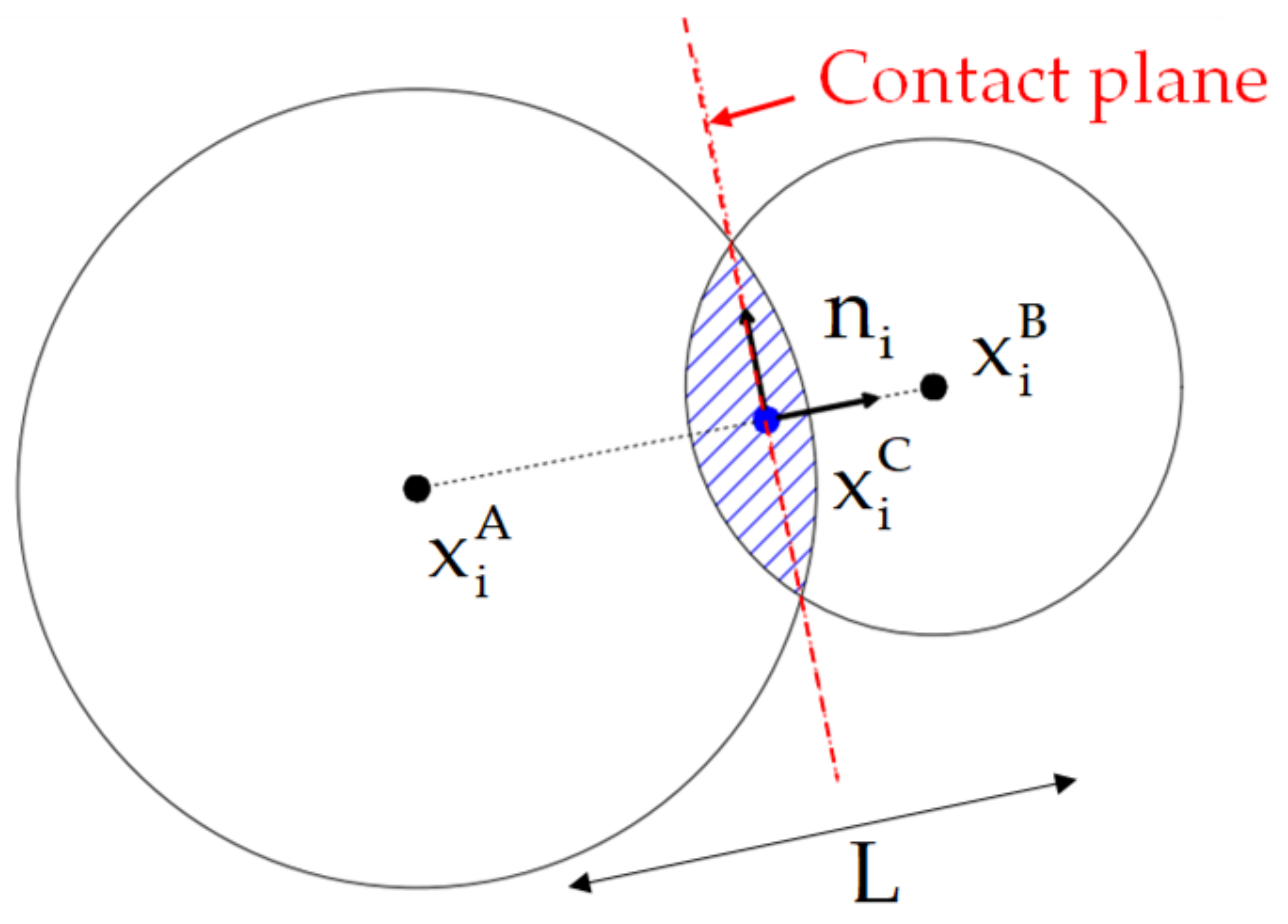
Like in the traditional point contact model [25,26], the contact unit normal, , is defined given the particles’ center of gravity and the inter-particle distance, (Figure 1):
The contact point location, , is also defined in the same way as in the traditional particle model [25,26]:
where is the contact overlap. The contact velocity of a given local contact point, which is the velocity of particle B relative to particle A, at the contact location is given by [25,26]:
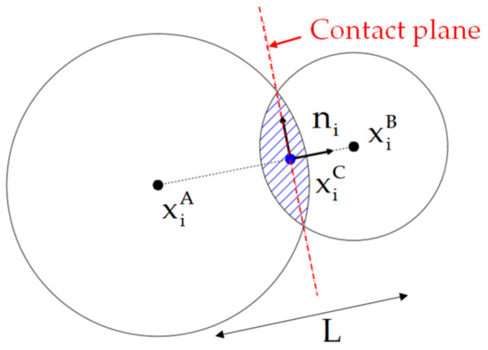
Figure 1.
Contact model associated geometry.
Figure 1.
Contact model associated geometry.
If the particle under analysis is a traditional rigid particle, the contact velocity at the contact point is defined using the particle kinematics [25,26]:
where is the permutation tensor. If the particle is a boundary particle associated with the edge of a given finite element, the contact velocity at the contact point is defined using the associated finite element nodal points kinematics and associated nodal shape functions:
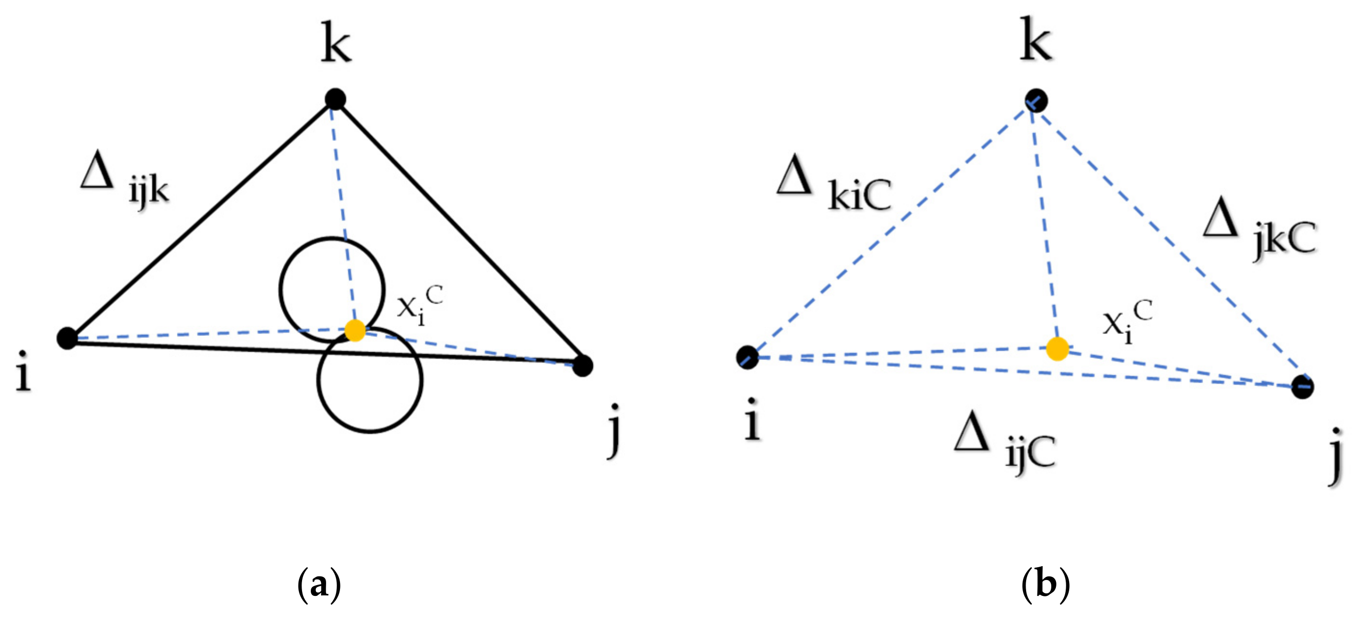
where is the shape function value associated with nodal point “” of the corresponding triangular finite element, , at the contact point location, , and is the velocity of nodal point “” of the corresponding triangular finite element (see Figure 2).

Figure 2.
Contact model triangular shape functions at the contact point: (a) setting the associated inner triangles given the contact location; (b) inner triangles adopted for shape function definition.
The triangular shape function values are defined in the traditional way according to the associated triangular areas (positive value clockwise; see Figure 2):
The finite element boundary particles motion is defined in a similar manner, but the adopted shape functions are defined at the particle’s center of gravity instead of being defined at the contact location.
The contact displacement normal increment, , stored as a scalar, and the contact displacement shear increment, , stored as a vector, are given by:
Given the normal and shear stiffnesses of the local contact point, the normal and shear forces increments are obtained following an incremental linear law:
The resultant contact force at the local contact point is then given by:
If the particle under analysis is a traditional rigid particle, the contact force is transferred to the particle’s center of gravity through equilibrium conditions [13,26]. If the particle is a boundary particle associated with a finite element edge, the contact force is then transferred to the nodal points of the associated finite element triangle given the nodal shape functions. For the triangular plane finite element associated with particle A, the local contact forces are distributed to each nodal point according to:
A similar procedure can be found if the particle B is part of a finite element boundary.
2.3. Numerical Stability
When only a steady state solution is sought, a mass scaling algorithm is adopted in order to reduce the number of timesteps necessary to reach the desired solution. The nodal point masses/rigid particles are scaled so that the adopted centered-difference algorithm has a higher rate of convergence for a given loading step. The nodal point scaled mass/particle mass used in the calculations is set assuming a unit time increment, , given the nodal point associated stiffness at a given time through:
The latter equation is the result of the application of Gershgorin’s theorem [28], which guarantees that the highest frequency of a structural system is less than or equal to the ratio of the sum of the absolute values of a row of the stiffness matrix and the sum of the mass matrix row. An upper bound of the translation stiffness, , associated with the finite element boundary particles contact model must be found at a given timestep:
where indicates a summation along the “” contacts associated with nodal point “”, and are the contact normal and shear stiffnesses, respectively, and is the shape function associated with nodal point “” of the triangular plane finite element associated with the inter-particle contact. For the rigid particles, a similar numerical scheme is adopted [13,26].
2.4. Contact Stiffness and Strength
In the following numerical simulations, the normal and shear contact stiffnesses are given by the following expressions:
where is the inter-particle distance, is the out-of-plane thickness of the particle assembly and is defined as the contact width, which is equal to the smallest diameter of the particles involved. For plane stress:
where and are the Young’s modulus and the Poisson’s ratio of the equivalent continuum material.
The total contact resistance () and the maximum cohesive force () are given as a function of the maximum tensile stresses () and the maximum cohesion stress () adopted at the contacts, and by the contact area, according to the following expressions:
2.5. Contact Constitutive Model
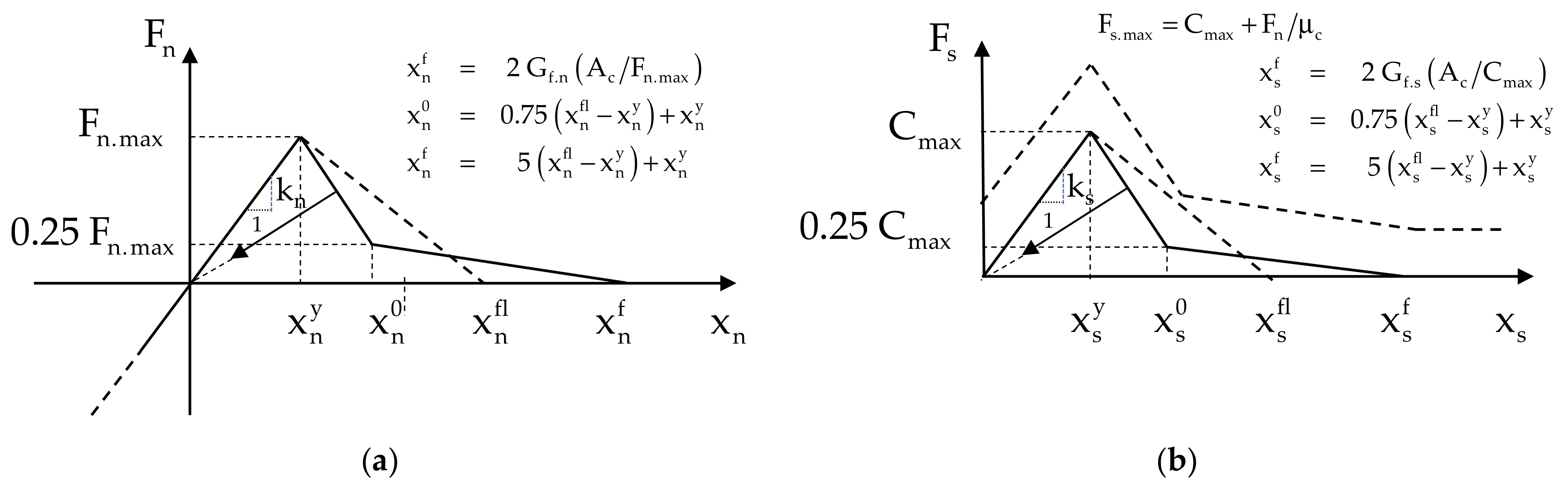
Figure 3 shows the bilinear softening contact model adopted in the normal and shear directions [13,26]. This contact model requires the definition of both the tensile fracture energy, , and the shear fracture energy, As presented in Figure 3, from the moment that the strength values (tensile and shear) are reached, the maximum tensile contact force and/or maximum shear contact force are reduced based on the current contact damage value, which varies between 0 (without damage) and 1 (in which the contact is considered cracked, only working in compression under pure friction). If the cracking occurs due to tensile/shear damage, the contact is considered to be a tensile crack, and if the cracking occurs in compression/shear, then the contact is considered to be a shear crack.

Figure 3.
Bilinear softening contact model: (a) normal direction; (b) shear direction [13,26].
2.6. Model Generation
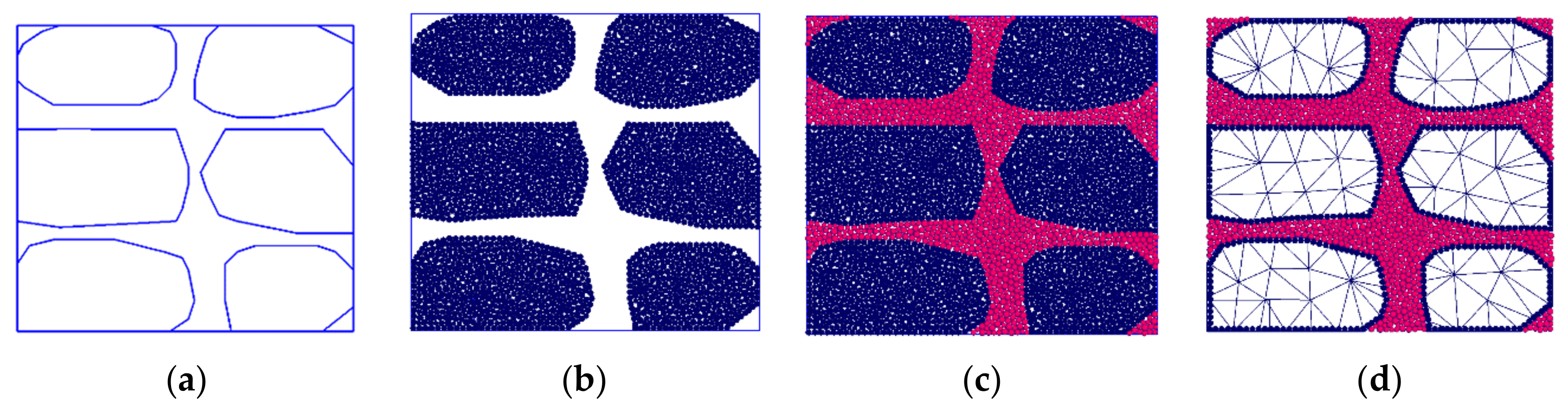
After knowing the stone geometry and placement in the masonry wall (Figure 4a), firstly, the space corresponding to the interior of each stone is discretized with inner particles (Figure 4b). Following this, the space corresponding to the external domain of each stone, which corresponds to the laying mortar, is also discretized with particles (Figure 4c). The hybrid PM particle model that is proposed requires a fourth step, in which each stone is discretized with finite elements and only the boundary stone particles are kept (Figure 4) in order to maintain the initial boundary roughness characteristic of the initial all-particle model (Figure 4).

Figure 4.
Discretization of a stone masonry wall adapted from [13]. (a) Rubblestone masonry wall; (b) Stone discretization; (c) Mortar discretization; (d) Stone particle discretization replaced by inner finite element mesh; only boundary particles are kept.
By keeping the stone boundary particles present in the all-particle DEM model, the proposed hybrid model maintains, as closely as possible to a DEM all-particle model, the contact interaction of the stone units with the outer particles representing the mortar. To predict a similar response with the proposed hybrid model and the all-particle DEM model, two important issues need to be addressed: (i) both models should have a similar stone inner deformability, and (ii) in both models, the interaction of the stone boundary particles with the neighboring particles representing the mortar should be kept as close as possible.
The stone subdomains are considered deformable, either through the inner contacts, in an all-particle DEM model, or through an FE discretization, in the hybrid proposal. The proposed hybrid model allows for runtime reduction because it requires, for deformability purposes, a reduced number of finite elements when compared to the required number of inner particles and inner inter-particle contacts adopted in the all-particle DEM model (see Figure 4c,d).
The adopted particle size distribution for the mortar and stone units should be chosen to be as close as possible to the real granular distribution of the material to be modelled. Due to computational restrictions, larger grain dimensions may be adopted. Regardless of the adopted grain size distributions for the mortar and stone units, in order to predict similar results to an all-particle DEM model, it is mandatory to keep the particle interlock that occurs between the particles representing the stone units and the particles representing the mortar, as occurs in the proposed hybrid model.
2.7. Model Parameters and Calibration Procedure
The elastic response associated with the proposed particle model is related with the elastic contact properties and of the equivalent continuum material and with the Young’s modulus and the Poisson’s coefficient of the triangular finite elements adopted in the inner discretization of each stone. The macroscopic strength response of the particle model requires the definition of five strength parameters associated with the contacts.
One of the main disadvantages of particle models is that it is not possible to devise analytical expressions for the elastic and strength contact properties. For this reason, it is necessary to calibrate them based on experimental results. In general, uniaxial compression, uniaxial tensile, splitting or bending tests are adopted. Figure 5 shows the final crack patterns for a given mortar under different elementary tests. In order to have a more thorough calibration, one should know not only the peak values but also the full stress/deformation curve and the full details of the loading equipment.

Figure 5.
Final crack patterns: (a) Tensile test 0.04 m × 0.04 m × 0.04 m; (b) Compression test 0.04 m × 0.04 m × 0.04 m); (c) Bending test 0.14 m × 0.04 m × 0.04 m.
In masonry micro-modelling based on the finite element method, complex cohesive contact models have been devised including cyclic behavior [29]. Nevertheless, it is complex to reproduce all the phenomena with a macroscopic constitutive law. As mentioned in [23], the cyclic model proposed in [29] requires a significant number of parameters and experiences severe convergence difficulties upon a large number of cycles or large displacements. With a particle model approach, where the physical particle interactions and the material randomness associated with the grain structure are taken directly into account, the failure phenomena are an emergent property, and the development of cracks and rupture surfaces appears naturally as part of the simulation process given its discrete nature. From our point of view, this advantage compensates the need for calibration under simple tests.
3. Case Studies
3.1. Uniaxial Compression and Tensile Tests—Comparison of Hybrid and All-Particle Models
In order to validate the hybrid model and to assess its performance, a comparison is made between the proposed hybrid model, the hybrid model as proposed in [15] and an all-particle assembly representing a heterogeneous particle assembly resembling concrete material under uniaxial tensile and compression test conditions. The uniaxial tensile tests were performed in 100 by 50 mm assemblies, and the uniaxial compression tests were performed in 100 by 100 mm assemblies (Figure 6).

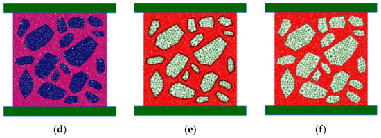
Figure 6.
Particle models adopted for uniaxial testing: (a) Tensile test (DEM); (b) Tensile test (H-FEM-DEM-A); (c) Tensile test (H-FEM-DEM-B) [15]; (d) Compression test (DEM); (e) Compression test (H-FEM-DEM-A) and (f) Compression test (H-FEM-DEM-B) [15].
In each uniaxial test, three different particle models were tested: (i) an all-particle model with the aggregates being discretized with particles (DEM); (ii) a hybrid particle model as proposed in this work that keeps the aggregate boundary particles (H-FEM-DEM-A); and iii) a hybrid particle model as proposed in [15], where the interaction is between the outer edges representing the aggregates and the rigid particles representing the mortar (H-FEM-DEM-B). In the adopted numerical models, the loading plates are not allowed to rotate and do not impose any shear restraint on the particle assembly.
Table 1 presents the adopted contact properties that need to be specified in the particle models. Different contact properties are adopted for the inter-particle contacts between the aggregate particles (AA), the aggregate and the mortar particles (AM) and between mortar particles (MM). For the plane stress triangular elements adopted in the hybrid models, a Young’s modulus of 25.5 GPa and a Poisson coefficient of 0.20 were considered.

Table 1.
Contact elastic and strength properties for uniaxial compression and tensile tests.
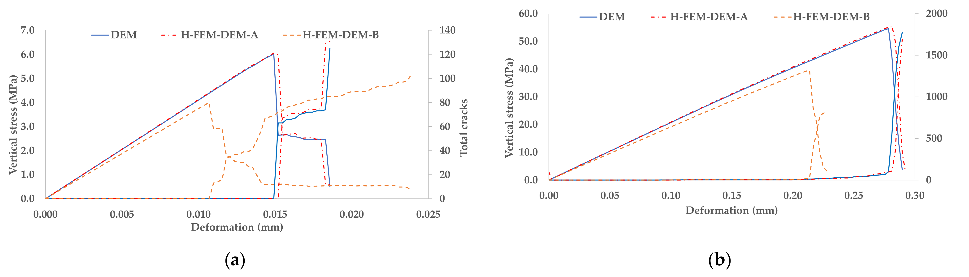
Figure 7 presents the stress-deformation curves and the crack evolution obtained with three particle models under uniaxial tensile and uniaxial compression. It is shown that the hybrid model that is proposed (H-FEM-DEM-A) has a stress/deformation and crack evolution very similar to the diagrams predicted with an all-particle assembly (DEM), contrary to the diagrams predicted with the hybrid model proposed in [15], which does not keep the boundary roughness, i.e., the peak values are significantly lower and the crack evolution is also different. The predicted results with the proposed hybrid model clearly show the importance of keeping the boundary particles in order to have particle/particle interactions similar to those that occur in an all-particle model. Another important aspect is that the inner aggregate FE discretization has to predict a deformability similar to that predicted with an inner particle discretization. The excellent agreement between the proposed hybrid model and the all-particle model clearly indicates that the aggregates have similar deformability.

Figure 7.
Stress/Deformation diagram and crack evolution for uniaxial tests: (a) tensile test; (b) compression test.
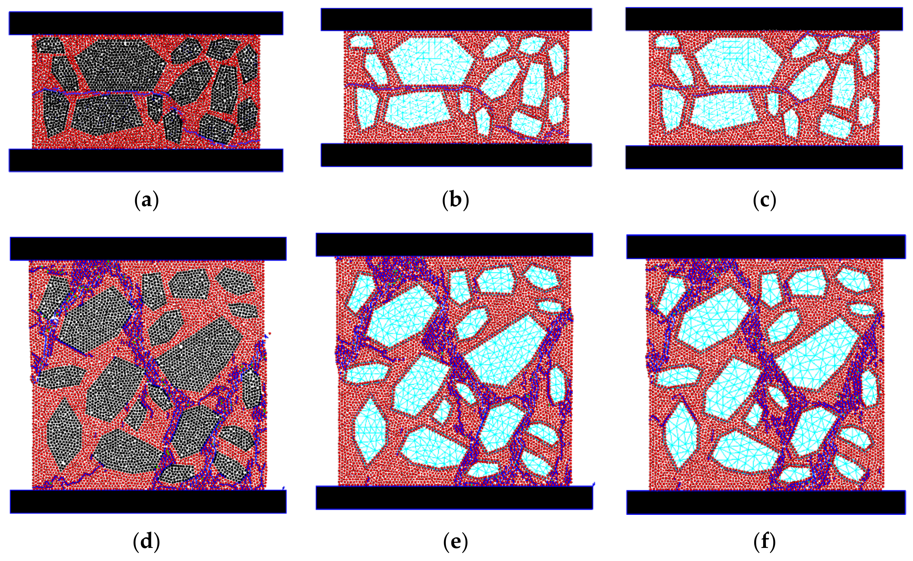
The final crack patterns obtained in uniaxial tensile and uniaxial compression are presented in Figure 8. In all the particle models, a crack perpendicular to the load direction that traverses the load direction is predicted in the tensile tests, and in the compression tests, the final crack patterns that are obtained are also expected when there is no friction at the loading boundaries. The presented results clearly show that it is only possible to obtain crack patterns similar to an all-particle DEM model with a hybrid model that keeps the boundary particles.

Figure 8.
Final crack pattern for uniaxial testing: (a) Tensile test (DEM); (b) Tensile test (H-FEM-DEM-A); (c) Tensile test (H-FEM-DEM-B) [15]; (d) Compression test (DEM); (e) Compression test (H-FEM-DEM-A) and (f) Compression test (H-FEM-DEM-B) [15].
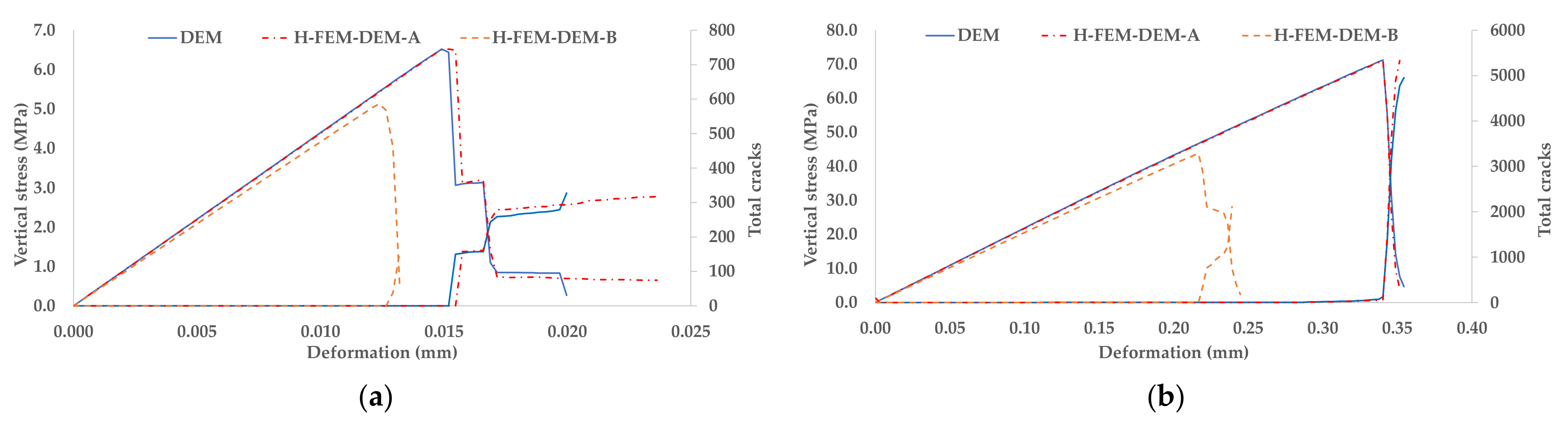
In order to assess the effect of the particle resolution in the performance of the proposed hybrid model, particle assemblies with half of the previous radius distribution were adopted in the inner discretization of the aggregates and in the mortar discretization (circular particles with radiuses ranging from 0.3 mm to 0.4 mm). Figure 9 presents the stress-deformation curves and the crack evolution obtained with the three particle models under uniaxial tensile and uniaxial compression. The final crack patterns obtained under uniaxial tensile and uniaxial compression are presented in Figure 10. As in in the coarser particle assemblies, it is shown that the hybrid model that is proposed (H-FEM-DEM-A) has a stress/deformation, a crack evolution and a final crack pattern very similar to those predicted with an all-particle assembly (DEM), contrary to the values predicted with the hybrid model proposed in [15]. Independently of the degree of particle refinement adopted in the particle assemblies discretization, there is always a grain interlock on the all-particle DEM model that only the hybrid proposed model is able to capture by keeping the outer boundaries’ particles.
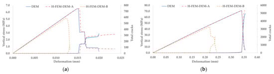
Figure 9.
Stress/Deformation diagram and crack evolution for uniaxial tests—refined particle assembly: (a) tensile test; (b) compression test.
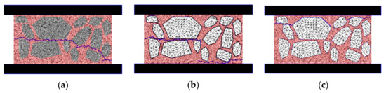

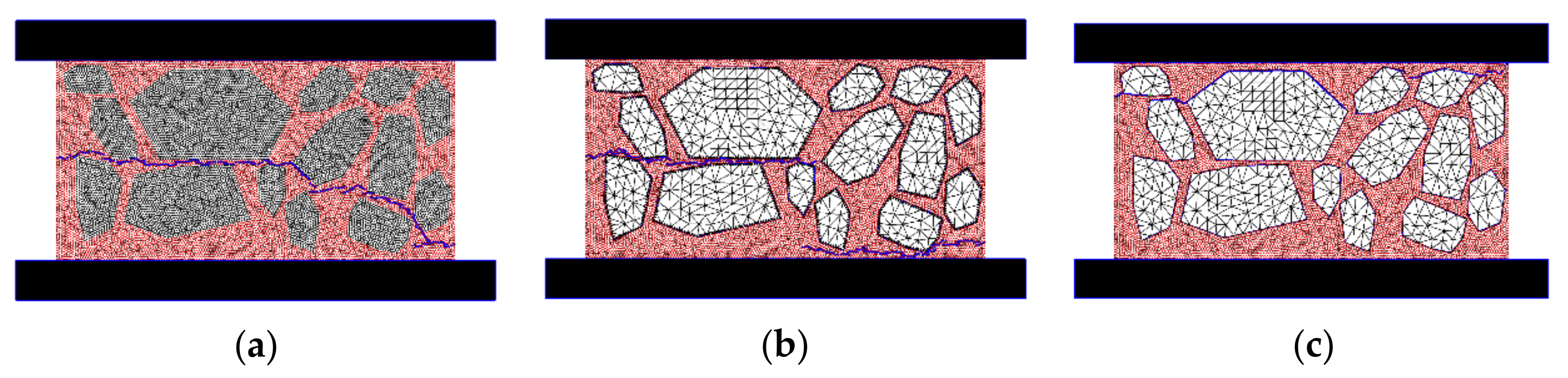
Figure 10.
Final crack pattern for uniaxial testing– refined particle assembly: (a) Tensile test (DEM); (b) Tensile test (H-FEM-DEM-A); (c) Tensile test (H-FEM-DEM-B) [15]; (d) Compression test (DEM); (e) Compression test (H-FEM-DEM-A) and (f) Compression test (H-FEM-DEM-B) [15].
Table 2 presents the computational execution times for the all-particle DEM model and for the proposed hybrid model (coarse and refined particle assembly). As shown, for the uniaxial tests presented here, the proposed hybrid model, when compared with an all-particle model, allows for a significant computational run time reduction of 20% to 25% for the coarse particle assembly and of 34% to 39% for the refined particle assembly, but it still predicts similar macroscopic behavior. The increase in the computational run time reduction obtained in the refined particle assembly is due to the fact that a higher number of inner particles and inner contacts are replaced by the same FEM aggregate discretization.
Table 2.
Execution times (hours) for uniaxial compression and tensile tests.
3.2. Modelling of Experimental Shear Tests of Masonry Walls
The capacity of the hybrid particle model is assessed in shear tests of wall panels with vertical loading, performed by Vasconcelos [22]. The wall geometry and typology follow that adopted in the experimental tests, where static cyclic tests with a given pre-compression were executed in both regular dry joint walls and rubble mortared walls.
3.2.1. Dry Masonry Walls
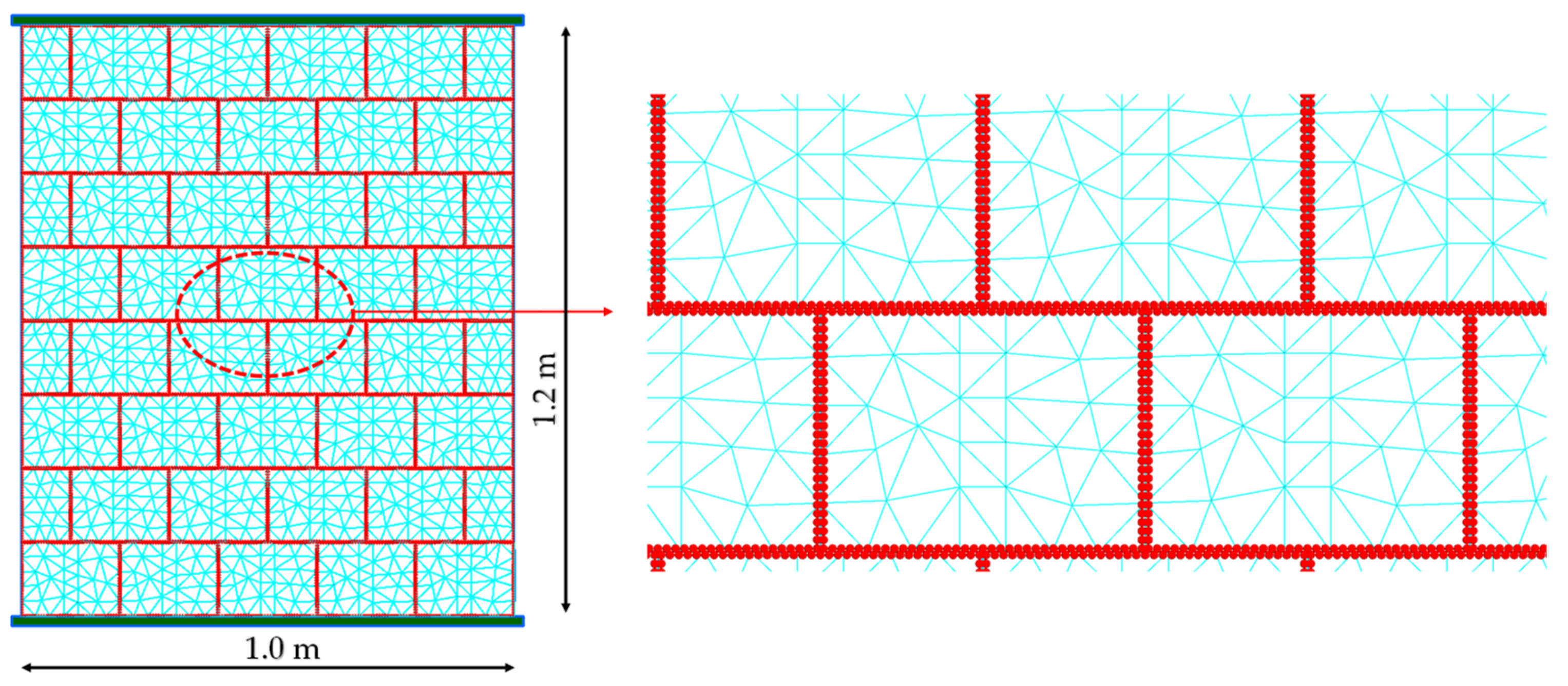
The proposed hybrid particle model is adopted in the analysis of dry joint walls in order to further assess its performance and to further validate the proposed hybrid algorithm. The stone units of the dry joint wall were discretized with a finite element mesh, as shown in Figure 11. The inset in the figure shows the particle discretization at the boundary of each stone. In order to model a smooth contact interaction, the interior boundary particles interact with the edge of the neighboring finite elements, following the algorithm presented in [15], in which rigid particles are allowed to interact with the finite element edges through normal and shear springs (H-FEM-DEM-wall). A hybrid particle model with a given surface roughness, particle-particle interaction (H-FEM-DEM-ball), was also adopted.

Figure 11.
Hybrid discretization for the dry wall test.
The elasticity of the stone units is represented by finite elements with a Young’s modulus of 20.2 GPa and a Poisson’s ratio of 0.20, which are the macroscopic values that were experimentally obtained by Vasconcelos [22]. In the numerical tests, the supports were modelled using rectangular polygonal rigid elements which are connected to the neighboring particles. The lower plate is fixed, whereas the upper plate has a constant vertical force corresponding to the pre-compression level and a prescribed horizontal displacement. The upper plate does not have its rotation restrained following the experimental test setup. In [23], a finite element model was developed, which is shown to predict well the in-plane shear wall behavior for different pre-compression values.
The stone wall could have been assessed with a rigid or flexible polygonal based DEM model [3,4] or finite/discrete element model [7,8], but with this example, it is shown that the proposed hybrid model is able to predict reasonable results under large displacements. Compared to a flexible DEM model, the proposed model has the advantage of making the contact discretization independent from the adopted finite element mesh discretization used for deformation purposes. In addition, the contact area between two deformable blocks is not required to be updated at each cycle, as the contact area is always given by the particle diameter that interacts with the neighboring wall or particle.
The hybrid particle model also works well for non-convex particles, because it only requires simple particle/wall or particle/particle interactions. When compared to a flexible polygonal DEM model, the proposed model is computationally more intensive, as it requires more particles in the boundary discretization in order to approximate the contact areas well.
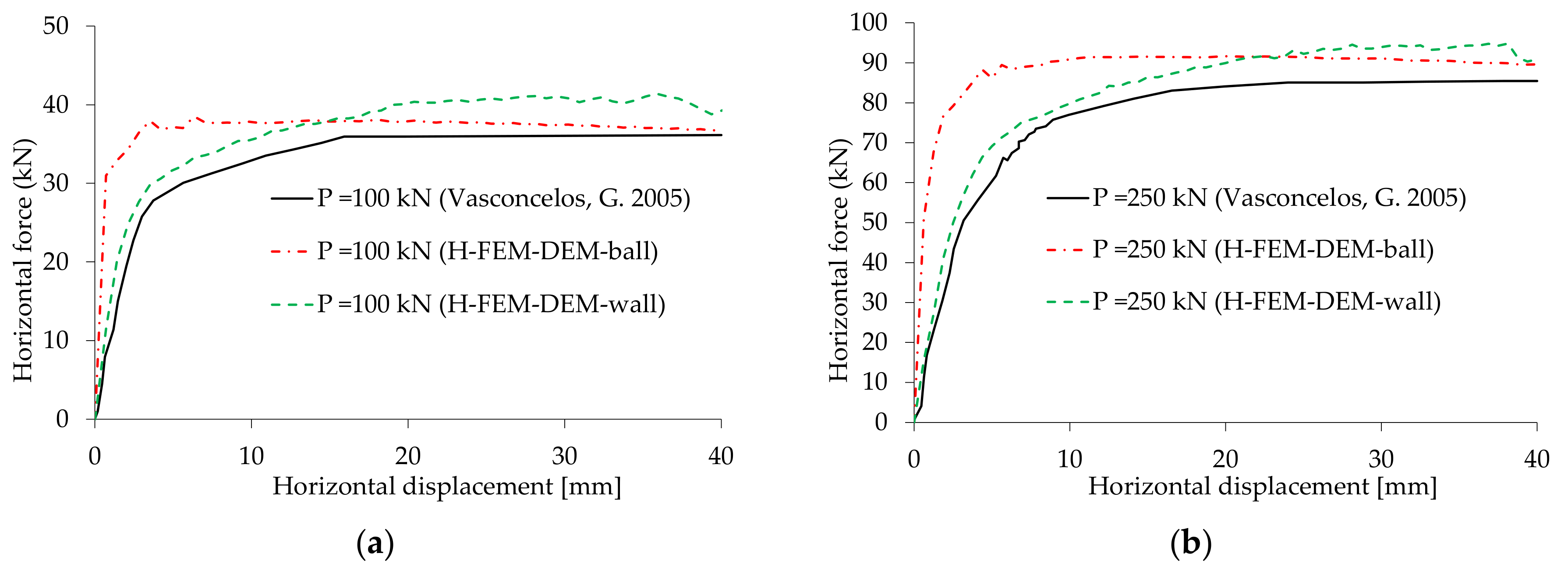
A pure friction model was adopted for the particle/wall and particle/particle contacts. The contact stiffnesses related to the vertical pre-compression loads is presented in Table 3. The adopted friction angle is the value obtained experimentally for the granite stones [22]. Figure 12 shows the force displacement diagrams obtained for the monotonic shear tests for the several pre-compression levels and for the two adopted particle models. It can be seen that the H-FEM-DEM-wall model, which mimics a smooth joint, is in good agreement with the experimental values, as there is first an elastic response followed by a clear yield plateau. It is important to note that, in the experiment, the non-linear behavior of the stone units was not noticed [22], which indicates that the elastic model adopted for the stone units gives a good approximation. The higher initial stiffness that is obtained with the H-FEM-DEM-ball model, which includes the surface roughness, is mainly due to the aggregate interlock that occurs at the neighboring particle/particle contacts (see Figure 11).
Table 3.
Contact elastic and strength properties for dry shear wall.

Figure 12.
Horizontal force displacement relationship for dry wall monotonic shear tests; comparison with the experimental results adapted from [20]: (a) 100 kN pre-compression vertical load; (b) 250 kN pre-compression vertical load.
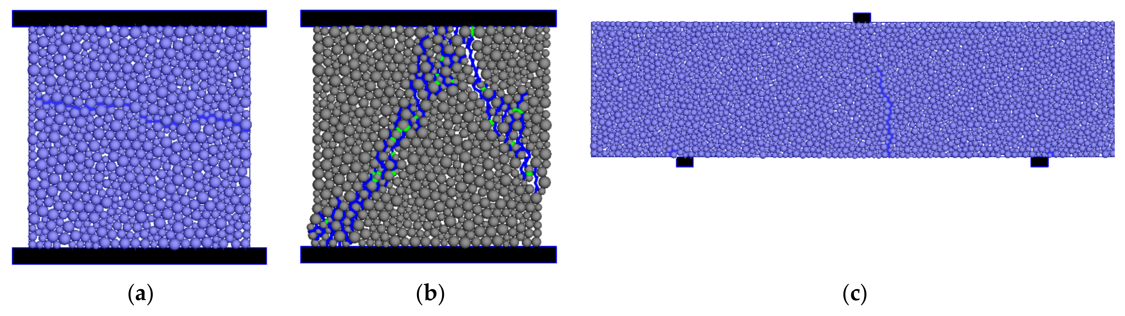
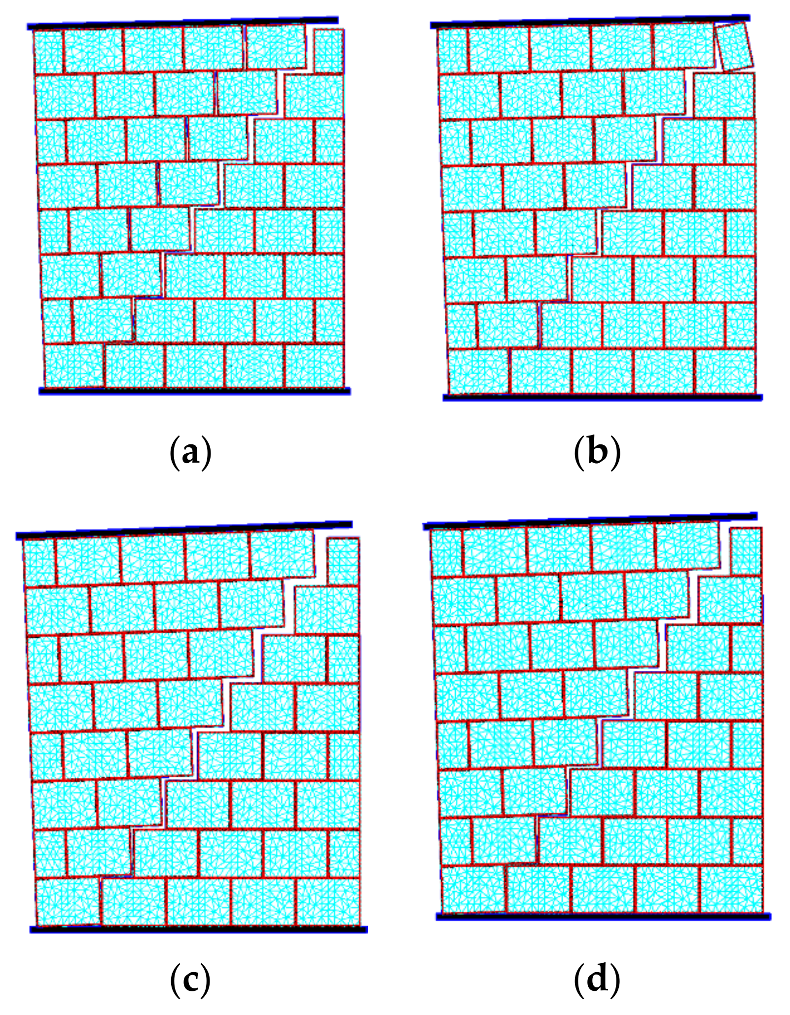
Figure 13 shows the final stone wall displacement configurations for the smooth contact joint and for the rough joint at the horizontal displacement of 40 mm for both vertical pre-compression values. The predicted displacement field closely follows the experimental configurations [22].

Figure 13.
Final stone wall displacement configuration for a horizontal displacement of 40 mm: (a) 100 kN pre-compression vertical load—H-FEM-DEM-wall; (b) 250 kN pre-compression vertical load—H-FEM-DEM-wall; (c) 100 kN pre-compression vertical load—H-FEM-DEM-ball; (d) 250 kN pre-compression vertical load—H-FEM-DEM-ball.
As shown in Figure 13, the particle model with a given boundary roughness predicts a similar final configuration, but the higher interlock leads to smaller displacements. For both vertical pre-compression loads and for both particle models, the flexure cracks initially appear, and at a later stage, a diagonal stepped crack is formed along the bed and head joints, and the final failure mechanism is of a rocking type where the upper part of the wall tends to rotate around the lower corner (see Figure 13). As shown in Figure 13, the dominant shear crack that is formed is more localized for a higher vertical pre-compression value (250 kN), particularly noticeable in the smooth joint model (Figure 13b). The presented results clearly show that the proposed hybrid particle model is able to handle large contact displacement interactions.
3.2.2. Rubble Masonry Walls
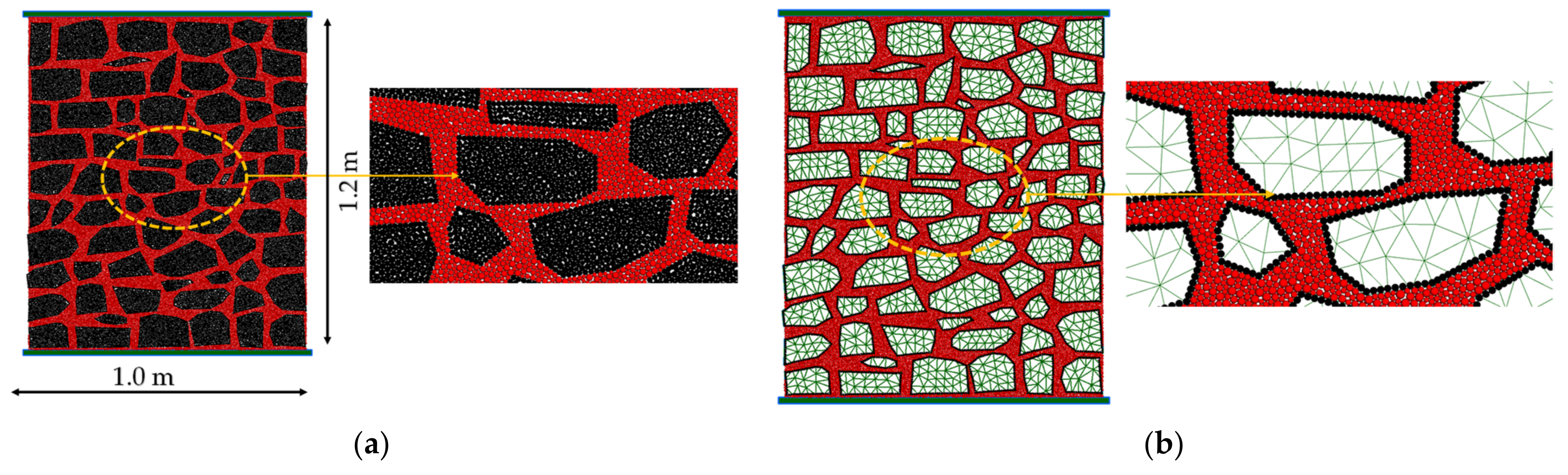
The proposed hybrid DEM/FEM model is further validated using uniaxial compression tests and shear tests with an initial pre-compression axial force of wall panels tested in [22]. Figure 14 shows the adopted wall geometry, the all-particle DEM numerical model (DEM) and the hybrid DEM/FEM proposed numerical model (H-FEM-DEM-A). The numerical models are based on the digital images of irregular mortared walls presented in [22].

Figure 14.
Numerical model of the rubble masonry walls tested in [22]: (a) all-particle model (DEM); (b) proposed hybrid model (H-FEM-DEM-A).
The particle generation procedure follows the principles discussed in Section 2.6. The rubble wall geometry has 80 stone units. In the all-particle DEM model, a total of 21,665 particles representing the stone units and a total of 11,394 particles representing the mortar are adopted. A total of 54,245 stone-stone contacts, 8784 contacts of the type stone-mortar and 26,828 contacts of the type mortar-mortar are presented in the particle model. The contacts are established adopting a particle distance threshold value of 0.25. In the proposed hybrid DEM/FEM model, only 4610 particles at the stone boundaries are kept, and the FEM discretization adopted inside the stones has 1624 nodal points and 1958 triangular plane stress triangles.
As previously mentioned, to apply the particle model, it is necessary to calibrate the micro-properties of the stone units and mortar. With this purpose, uniaxial tensile and compression tests were carried out in quadrilateral specimens of 200 mm × 200 mm × 200 mm (see [13]). For the mortar representation and for the stone units, a uniform particle distribution of circular particles with radiuses ranging from 2.5 mm to 4.5 mm was adopted. The calibrated contact proprieties are presented in Table 4. The elasticity of the stone units is represented by finite elements with a Young’s modulus of 20.2 GPa and a Poisson’s ratio of 0.20, which are the macroscopic values that were experimentally obtained by Vasconcelos [22]. For the stone units, an elastic behavior was adopted.
Table 4.
Contact elastic and strength properties for the rubble masonry walls.
The uniaxial compression tests are performed adopting displacement control for the upper plate represented by a polygonal type element which interacts with the particle assembly through contact interaction in a manner similar to the contact formulation described in Section 2. Only normal interaction is allowed to occur between the plates and the particle assembly (low friction). The upper and lower plates are not allowed to rotate.
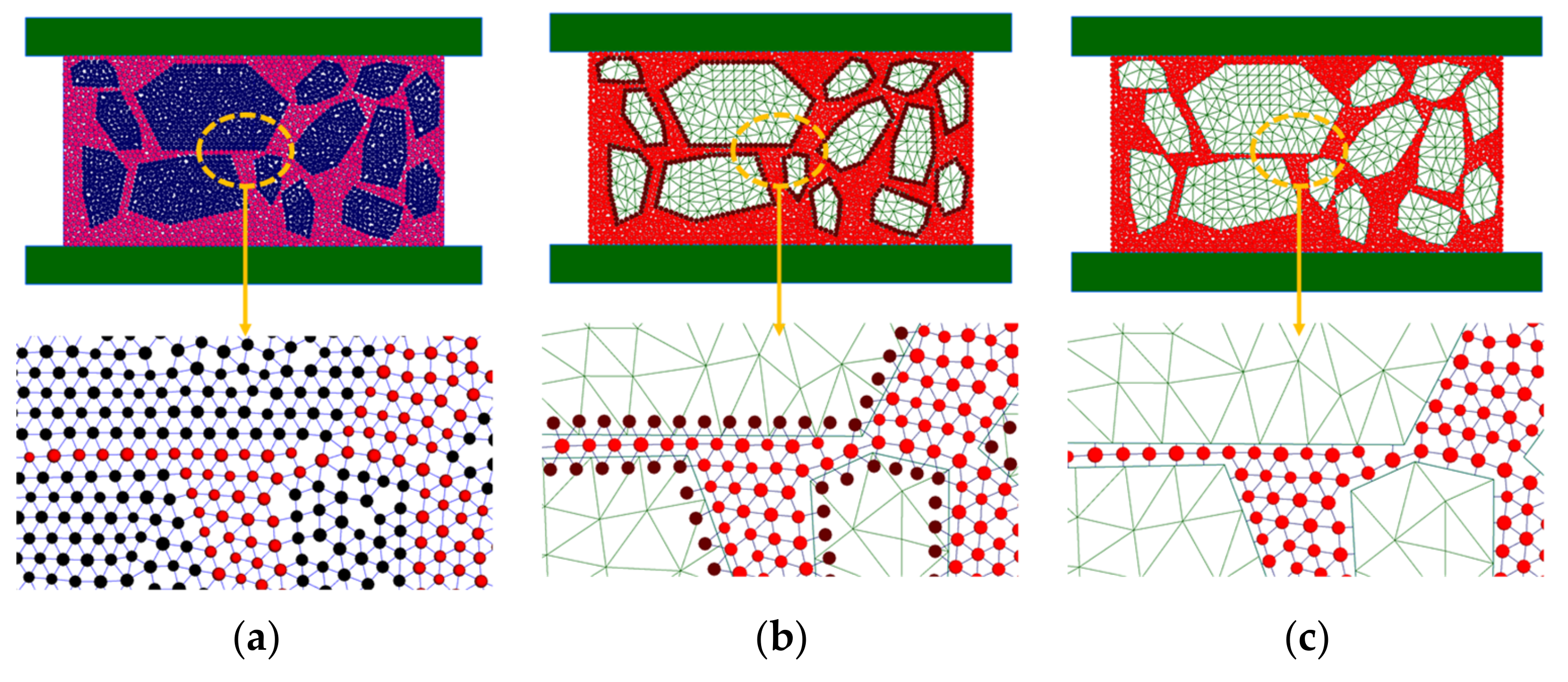
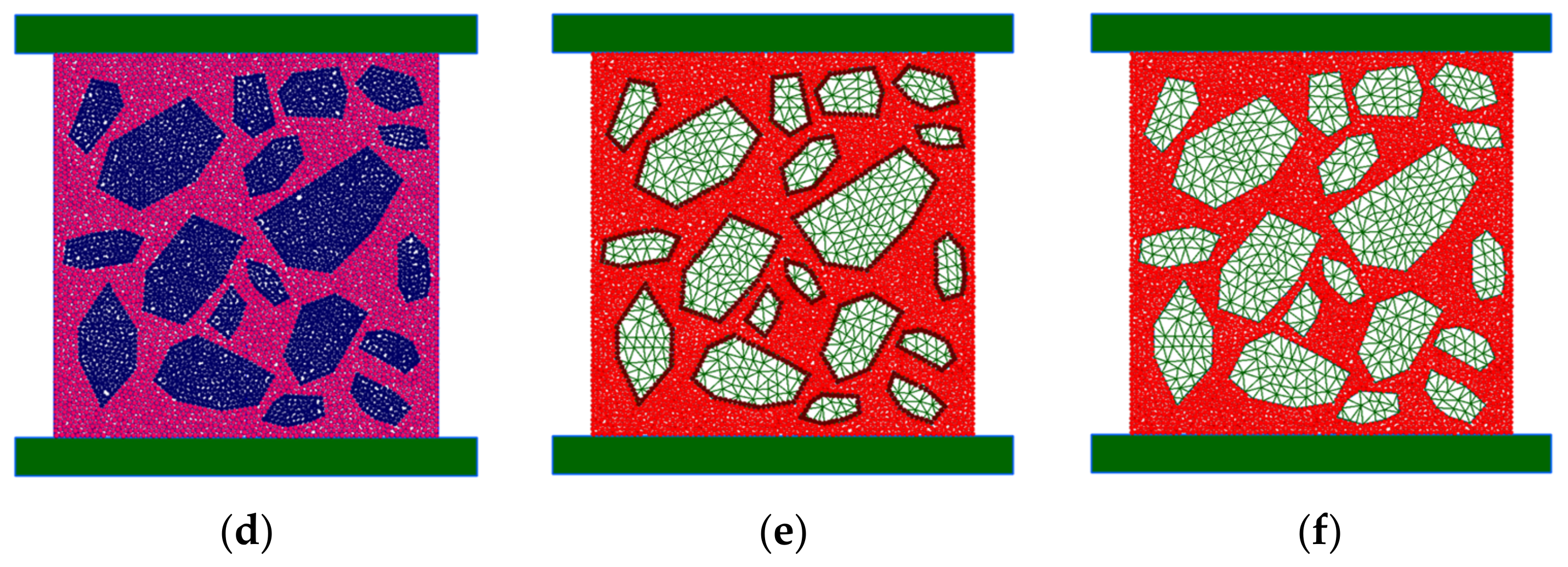
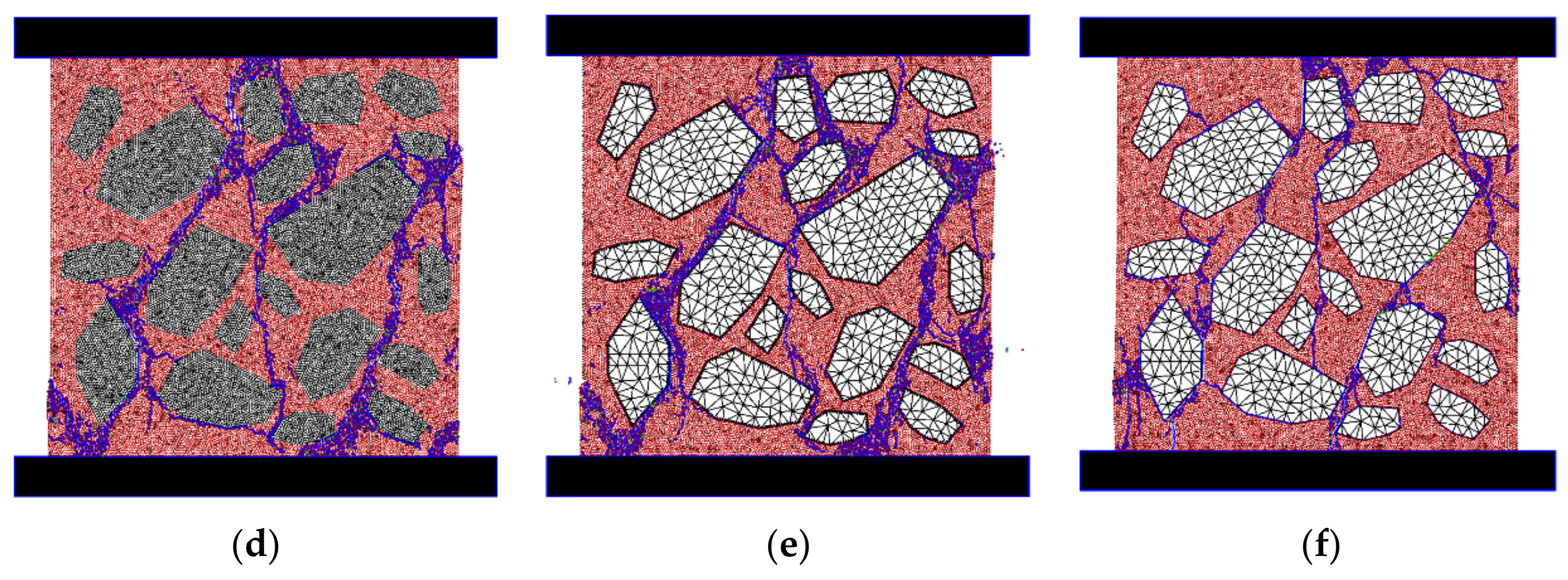
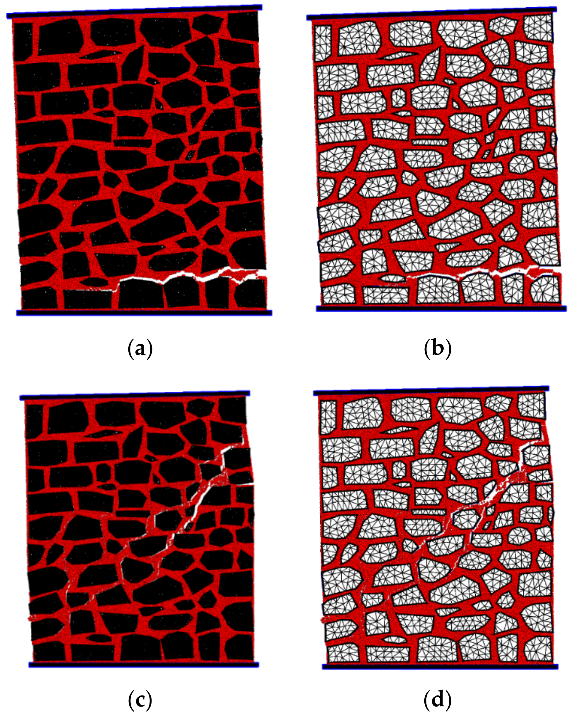
Figure 15 shows the final crack patterns associated with the rubble wall arrangement for the all-particle model (DEM), for the proposed hybrid DEM/FEM particle model (H-FEM-DEM-A) and for the hybrid particle model as proposed in [15], where the interaction is between the outer edges representing the stones and the rigid particles representing the mortar (H-FEM-DEM-B). With the all-particle model, the expected crack pattern for a low plate friction example is obtained and the failure pattern is closer to the expected vertical cracking, but the presence of the stone units makes the crack pattern more tortuous. As shown, the proposed hybrid model is able to predict a very similar crack pattern, contrary to the smooth contact model [15].
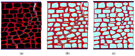
Figure 15.
Final crack patterns for uniaxial compression testing in rubble wall: (a) DEM; (b) H-FEM-DEM-A; (c) H-FEM-DEM-B [15].
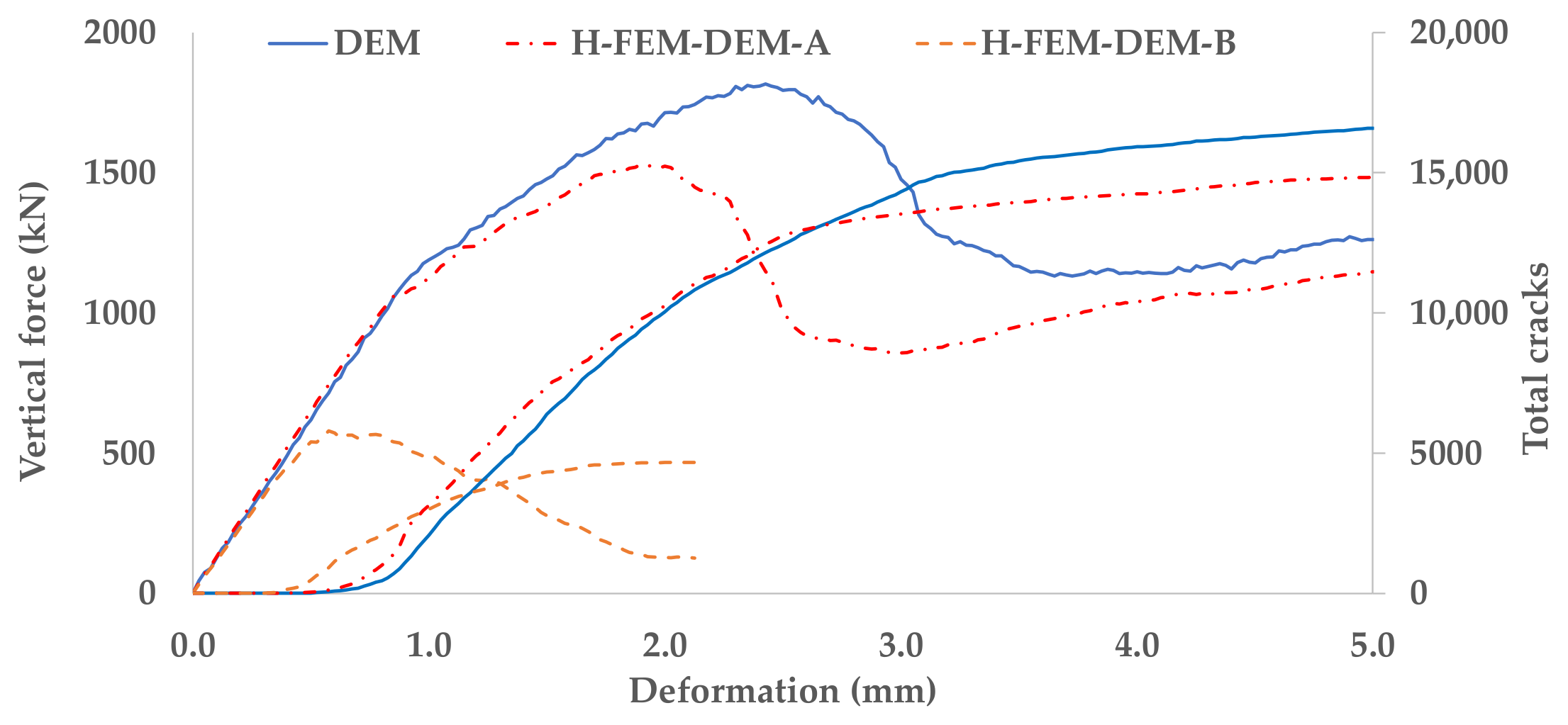
Figure 16 shows the force/displacement diagrams and the crack evolution obtained with the adopted particle models. As shown, the proposed hybrid model (H-FEM-DEM-A) has a force/deformation and crack evolution very similar to the diagrams predicted with all-particle assembly (DEM). The similarity between both models is not as strong as that predicted in Section 3.1 for the small sample size, but the hybrid model still gives a very reasonable approximation when compared with the diagrams predicted with the hybrid model proposed in [15] (H-FEM-DEM-B), namely, the peak values are significantly lower and the crack evolution is also different. The slight difference between the all-particle model and the proposed hybrid model is most likely due to the fact that some of the stones are very elongated and probably would require a higher particle discretization in order to have a similar deformability to that obtained with the adopted FE discretization mesh.

Figure 16.
Uniaxial compression tests in Rubble wall: force displacement diagrams.
The performance of the all-particle DEM numerical model (DEM) and the hybrid DEM/FEM proposed numerical model (H-FEM-DEM-A) was also compared adopting shear tests with initial pre-compression. A high friction plate (normal and shear contact force transmission) is adopted in both the upper and the lower plates. An initial pre-compression load is adopted (250 kN and 750 kN), followed by a lateral displacement of the upper plate [13]. The rotation motion is only restrained at the lower plate. The particle model H-FEM-DEM-B was not adopted in the shear tests analysis because its behavior under uniaxial testing is significantly different from the all-particle DEM model.
Figure 17 shows the final failure patterns obtained. For the lowest pre-compression force, the failure pattern is mostly associated with bending mechanics, and for the highest pre-compression value, the failure is also due to diagonal shear cracking. As shown, the proposed hybrid model is able to predict crack patterns very similar to those obtained with an all-particle model.

Figure 17.
Final displacement field for shear test in rubble wall with initial precompression (magnified 5 times): (a) DEM-250 kN; (b) H-FEM-DEM-A-250 kN; (c) DEM-750 kN; (d) H-FEM-DEM-A-750 kN.
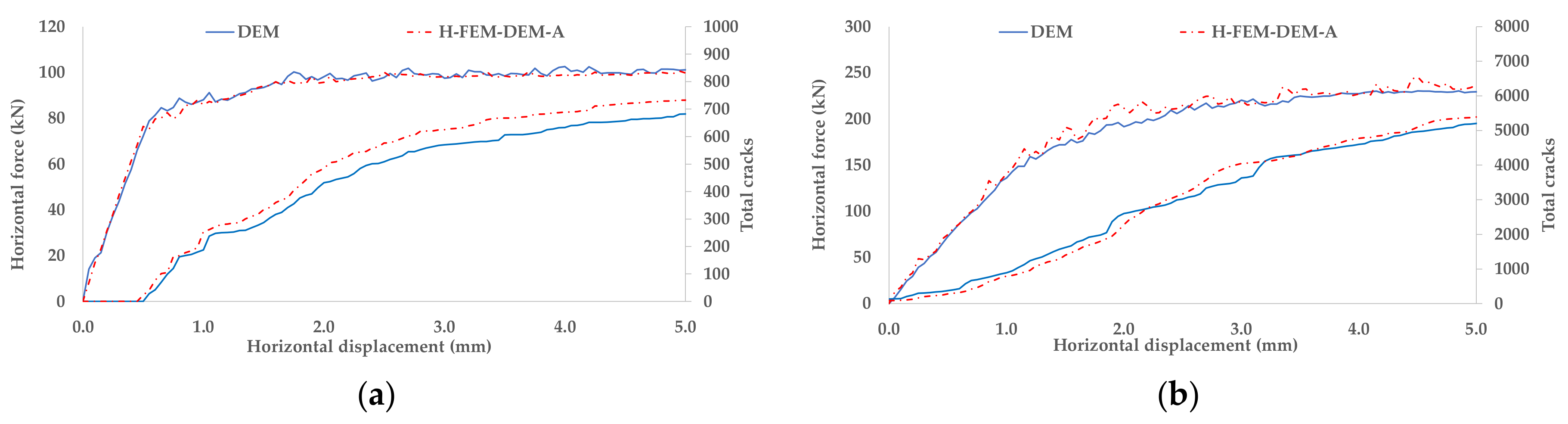
Figure 18 shows the horizontal force/horizontal displacement diagrams and the total crack evolution for both pre-compression values. It can be seen that, as expected, a higher initial pre-compression value leads to a higher peak shear load on both particle models. As shown in Figure 18, the proposed hybrid model (H-FEM-DEM-A) has a horizontal force/horizontal displacement and contact crack evolution very similar to those predicted with all-particle assembly (DEM) for both adopted pre-compression values.

Figure 18.
Shear test in rubble with initial precompression-force displacement diagrams. (a) 250 kN; (b) 750 kN.
Table 5 presents the computational execution times for the all-particle DEM model and for the proposed hybrid model for the several numerical tests carried out with the rubble masonry model. As shown, for the rubble wall tests presented here, the proposed hybrid model allows for a significant computational run time reduction of around 40% when compared with an all-particle model but, as shown, still predicts similar macroscopic behavior.
Table 5.
Execution times (hours) for the rubble masonry wall tests.
4. Discussion and Conclusions
Particle models, by taking directly into account the physical particle interactions and the material randomness associated with the grain structure, are able to predict complex macroscopic failure phenomena, and the development of cracks and rupture surfaces appears naturally as part of the simulation process given its discrete nature. These advantages clearly compensate for the fact that these types of models require a previous parameter calibration procedure using fundamental tests. The particle model can be interpreted as being a synthetic material that mimics the real material, which is calibrated using fundamental testing and then adopted in larger models [26].
For the above-mentioned reasons, particle models show great potential to handle particular masonry problems, namely, the study of traditional masonry structures with irregular stones, 3-leaf walls or rubble masonry. The computational resources available today allow for the detailed representation of materials by means of discrete element particle models, which have become a powerful tool to investigate the fundamental behavior of materials and structures.
Nevertheless, it is important to reduce the computational effort associated with particle models, and for this reason, a hybrid DEM/FEM particle model is proposed here, where the stone units that are expected to remain in the elastic range are discretized by finite elements. With the proposed model, only the particles at the stone boundary are kept, maintaining the initial stone surface roughness. This enhancement, as shown, allows for more refined discretization to be adopted in particle models, with a granulometry closer to the mortar/stone element, or for the possibility of applying particle models to larger structures.
The results that are presented, namely, the uniaxial tests in small samples and the uniaxial tests and shear tests in rubble masonry, clearly show the relevance of the proposed enhancements. The results presented show the relevance of keeping the outer particle boundaries adopted in the stone’s discretization in order to maintain the particle interactions that are present in an all-particle model. It is shown that it is only possible to predict a response similar to that predicted with an all-particle model by using the proposed hybrid FEM/DEM model, namely, the final crack patterns, crack evolution and overall response. It is also shown that, for the rubble masonry examples, the hybrid FEM/DEM allows for a significant computational run time reduction of around 40% and of around 20% to 25% for the small uniaxial tests that are presented.
The hybrid DEM/FEM particle model is also adopted in shear tests of dry masonry walls under different pre-compressions values. This type of walls can be modelled with a smooth contact joint either with polygonal DEM models [3,4] or with FEM models [23,29], which are computationally less demanding. Nevertheless, the presented numerical studies clearly show that the proposed model is able to handle large displacements, which is an important feature when adopting a micro-modelling approach. Additionally, there is the potential to adopt the developed particle model in the assessment of the stone surface roughness in the overall wall response. As mentioned, the boundary surface can be chosen independently from the FE discretization mesh, and the interactions are simple particle/particle and particle/wall, which allows for the proposed model to be applied in non-convex stones.
At present, the proposed particle model requires elastic behavior in the stones, which, for rubble-stone masonry walls built with hydrated air lime mortar [30], may be sufficient. However, for stronger mortars, it may be relevant to include the nonlinear behavior in some of the stones. Developments are being undertaken to allow for a switch from the hybrid FE model to the full DE on a given stone if a given limit stress state is reached. The presented results clearly show that keeping the outer boundary particles is one of the key ingredients in order to have a smooth transition between models. With the proposed hybrid model, it is also possible to represent some stones where nonlinearity is expected with an all-particle DEM model.
Author Contributions
Conceptualization, N.M.A.; methodology, N.M.A. and J.V.L.; software, N.M.A.; validation, N.M.A.; writing—original draft preparation, N.M.A. and J.V.L.; writing—review and editing, N.M.A. and J.V.L.; supervision, N.M.A.; project administration, N.M.A. and J.V.L. All authors have read and agreed to the published version of the manuscript.
Funding
This research received no external funding.
Institutional Review Board Statement
Not applicable.
Informed Consent Statement
Not applicable.
Data Availability Statement
Not applicable.
Acknowledgments
The study presented here is part of the ongoing project “DAMFA—Cutting-edge solutions for sustainable assessment of concrete dam foundations”, which is carried out at LNEC with the main purpose of developing a numerical multiphysics integrated tool for the sustainable assessment of concrete dam foundations, taking into account the interaction between mechanical, hydraulic and thermal behaviors.
Conflicts of Interest
The authors declare no conflict of interest.
References
- Lourenço, P.B. Computations of historical masonry constructions. Prog. Struct. Eng. Mater. 2002, 4, 301–319. [Google Scholar] [CrossRef]
- Lourenço, P.B.; Rots, J.G. A multi-surface interface model for the analysis of masonry structures. J. Eng. Mech. 1997, 123, 660–668. [Google Scholar] [CrossRef]
- Lemos, J.V. Discrete element modeling of masonry structures. Int. J. Archit. Herit. 2007, 1, 190–213. [Google Scholar] [CrossRef]
- Roberti, G.M.; Spina, O. Discrete element analysis of the Sardinian ‘Nuraghe’. In Proceedings of the 3rd International Seminar—Possibilities of Numerical and Experimental Techniques, University of Minho, Guimarães, Portugal, 7–9 November 2001; Lourenço, P.B., Roca, P., Eds.; University of Minho: Guimarães, Portugal, 2001; pp. 719–727. [Google Scholar]
- Gilbert, M.; Melbourne, C. Rigid-block analysis of masonry structures. Struct. Eng. 1994, 72, 356–361. [Google Scholar]
- Thavalingam, A.; Bicanic, N.; Robinson, J.; Ponniah, D.A. Computational framework for discontinuous modelling of masonry arch bridges. Comput. Struct. 2001, 79, 1821–1830. [Google Scholar] [CrossRef]
- Miglietta, P.C.; Bentz, E.C.; Grassel, G. Finite/discrete element modelling of reversed cyclic tests on unreinforced masonry structures. Eng. Struct. 2017, 138, 159–169. [Google Scholar] [CrossRef]
- Smoljanovic, H.; Živaljic, N.; Nikolic, Ž. A combined finite-discrete element analysis of dry stone masonry structures. Eng. Struct. 2013, 52, 89–100. [Google Scholar] [CrossRef]
- Smoljanovic, H.; Živaljic, N.; Nikolic, Ž.; Munjiza, A. Numerical analysis of 3D dry-stone masonry structures by combined finite-discrete element method. Int. J. Solids Struct. 2018, 136–137, 150–167. [Google Scholar] [CrossRef]
- Casolo, S.; Pena, F. Rigid element model for in-plane dynamics of masonry walls considering hysteretic behaviour and damage. Earthq. Eng. Struct. Dyn. 2007, 36, 1029–1048. [Google Scholar] [CrossRef]
- Petrinic, N. Aspects of Discrete Element Modelling Involving Facet-to-Facet Contact Detection and Interaction. Ph.D. Thesis, University of Wales, Cardiff, UK, 1996. [Google Scholar]
- Rouxinol, G.A.F.; Providência, P.; Lemos, J.V. Bridgemill bridge bearing capacity assessment by a discrete element method. In Proceeding of the 5th International Conference on Arch Bridges, University of Minho/University of Madeira, Madeira, Portugal, 12–14 September 2007; Lourenço, P.B., Oliveira, D.V., Portela, A., Eds.; University of Minho/University of Madeira: Madeira, Portugal, 2007; pp. 669–676. [Google Scholar]
- Azevedo, M.; Lemos, J.V.; Almeida, J.R. Discrete Element Particle Modelling of Stone Masonry. In Computational Modeling of Masonry Strutures Using the Discrete Element Method; IGI Global: Hershey, PA, USA, 2016; pp. 146–170. [Google Scholar]
- Massart, T.J.; Peerlings, R.H.J.; Geers, M.G.D. Structural damage analysis of masonry walls using computational homogenization. Int. J. Damage Mech. 2007, 16, 199–226. [Google Scholar] [CrossRef]
- Azevedo, N.M.; Lemos, J.V. Hybrid discrete element/finite element method for fracture analysis. Comput. Methods Appl. Mech. Eng. 2006, 195, 4579–4593. [Google Scholar] [CrossRef]
- Cusatis, P.; Bazant, Z.; Cedolin, L. Confinement-Shear Lattice Model for Concrete Damage in Tension and Compression: I. Theory. J. Eng. Mech. 2003, 129, 1439–1448. [Google Scholar] [CrossRef]
- Azevedo, N.M.; Lemos, J.V. A 3D generalized rigid particle contact model for rock fracture. Eng. Comput. 2013, 30, 277–300. [Google Scholar] [CrossRef] [Green Version]
- Ghazvinian, E.; Diederichs, M.; Quey, R. 3D Random Voronoi grain-based models for simulation of brittle rock damage and fabric-guided micro-fracturing. J. Rock Mech. Geotech. Eng. 2014, 6, 506–521. [Google Scholar] [CrossRef] [Green Version]
- Wang, Y.; Tonon, F. Modeling Lac du Bonnet granite using a discrete element model. Int. J. Rock Mech. Min. 2009, 46, 1124–1135. [Google Scholar] [CrossRef]
- Pina-Henriques, J.; Lourenço, P.B. Masonry compression: A numerical investigation at the meso-level. Eng. Comput. 2006, 23, 382–407. [Google Scholar] [CrossRef] [Green Version]
- Belytschko, T.; Yeh, S. The splitting pinball method for contact-impact problems. Comput. Methods Appl. Mech. Eng. 1993, 105, 375–393. [Google Scholar] [CrossRef]
- Vasconcelos, G. Experimental Investigations on the Mechanics of Stone Masonry: Characterization of Granites and Behaviour of Ancient Masonry Shear Walls. Ph.D. Thesis, Universidade do Minho, Guimarães, Portugal, 2005. [Google Scholar]
- Senthivel, R.; Lourenço, P.B. Finite element modelling of deformation characteristics of historical stone masonry shear wall. Eng. Struct. 2009, 31, 1930–1943. [Google Scholar] [CrossRef] [Green Version]
- Cundall, P. Distinct element models for rock and soil structure. In Analytical and Computational Methods in Engineering Rock Mechanics; Brown, E.T., Ed.; Allen & Unwin: London, UK, 1987; Chapter 4; pp. 129–163. [Google Scholar]
- Potyondy, D.; Cundall, P.A. A bonded-particle model for rock. Int. J. Rock Mech. Min. 2004, 41, 1329–1364. [Google Scholar] [CrossRef]
- Azevedo, N.M.; Candeias, M.; Gouveia, F. A Rigid Particle Model for Rock Fracture Following the Voronoi Tessellation of the Grain Structure: Formulation and Validation. Rock Mech. Rock Eng. 2015, 48, 535–557. [Google Scholar] [CrossRef]
- Williams, J.R.; O’Connor, R. A linear complexity intersection algorithm for discrete element simulation of arbitrary geometries. Eng. Comput. 1995, 12, 185–201. [Google Scholar] [CrossRef]
- Underwood, P. Dynamic relaxation. In Computation Methods for Transient Analysis; Belytschko, T., Hughes, T., Eds.; Elsevier Science Publishers B.V.: Oxford, UK, 1983; pp. 245–265. [Google Scholar]
- Oliveira, D.V.; Lourenço, P.B. Implementation of a constitutive model for the cyclic behaviour of interface elements. Comput. Struct. 2004, 82, 1451–1461. [Google Scholar] [CrossRef] [Green Version]
- Pinho, F.F.S.; Lúcio, V. Rubble stone masonry walls in Portugal: Material properties, carbonation depth and mechanical characterization. Int. J. Archit. Herit. 2017, 11, 685–702. [Google Scholar]

Publisher’s Note: MDPI stays neutral with regard to jurisdictional claims in published maps and institutional affiliations. |
© 2022 by the authors. Licensee MDPI, Basel, Switzerland. This article is an open access article distributed under the terms and conditions of the Creative Commons Attribution (CC BY) license (https://creativecommons.org/licenses/by/4.0/).