Article

A Study of the Mechanical Response of Nonwovens Excited by Plate Vibration

1
Institute of Mechanism Theory, Machine Dynamics and Robotics (IGMR), RWTH Aachen University, 52062 Aachen, Germany
2
Institut für Textiltechnik (ITA), RWTH Aachen University, 52074 Aachen, Germany
3
Institute of General Mechanics (IAM), RWTH Aachen University, 52062 Aachen, Germany
*
Authors to whom correspondence should be addressed.
Appl. Mech. 2022, 3(2), 496-516; https://doi.org/10.3390/applmech3020029
Submission received: 16 March 2022 / Revised: 14 April 2022 / Accepted: 21 April 2022 / Published: 24 April 2022

Abstract

:
Nonwovens are a type of textile that possess a wide range of unique properties, such as lightweight and damping characteristics, which make them suitable for many applications as in medicine and engineering. In this study, the focus lies on the mechanical response of nonwovens as a multiphase porous layer excited by an underlying vibrating plate. The material properties of the nonwovens are characterized via laboratory measurements applied to different samples. In particular, a dynamic analysis of the underlying thin plate is carried out to obtain its eigenmodes and, thus, the maximum response. These eigenmodes are then utilized in the boundary conditions in an advanced numerical porous media model to simulate the dynamic response of the anisotropic fibrous material. To understand the coupled processes in the fibrous textile material, a three-dimensional initial-boundary-value problem of porous media dynamics is introduced. The numerical results demonstrate the capability of the proposed model to realize the interplay between the pore-air pressure and the effective stresses during nonwovens vibration and, thus, the role of the pore air in vibration-induced fiber-fiber friction reduction as well as the effectiveness of the nonwovens in the dissipation of the kinetic energy, i.e., damping propagating acoustic waves.

1. Introduction

Nonwovens are types of textile that are loosely defined as ’manufactured sheet, web or batt of directionally or randomly orientated fibers, bonded by friction and/or cohesion and/or adhesion’. Because of their high porosity, low production costs, as well as their excellent range of configurations, nonwovens are popular materials for sound insulation applications [1]. Examples for nonwoven sound insulators include the use as acoustic wall claddings, appliances like washing machines and in the automotive industry, where the fabrics not only fulfill an aesthetic but also a sound-insulating functionality. In this, the goal is to fit as much sound-insulating functionality in as little space as possible. The adaptability of nonwovens gives engineers the freedom in choosing the right parameters for a given application. For an efficient engineering process, the effects of nonwoven parameters on the sound insulation performance need to be studied [2].
This paper proposes a mechanism of excitation in which the porous fabric is in a direct contact with a solid surface (plate). Examples of the described mechanism include sound insulation on automotive doors or household appliances like washing machines. The nonwoven element is in direct contact with a metallic plate, which is excited by different vibration sources resulting in deformation of the plate surface. The plate surface itself radiates sound into the air. The engineering task is to suppress sound radiation using suitable insulators like nonwovens. The mode of excitation of the fabric is an imposed displacement on the surface, not an imposed pressure from an acoustic wave. The fabric acts as a decoupling device rather than an insulator.
One of the main aims in this contribution is to understand the mechanism of acoustic wave propagation and attenuation in nonwovens while treating them as a multiphase porous material with interacting solid phase (fibers) and fluid phase (interstitial air). To this end, the Theory of Porous Media (TPM) is used in the continuum mechanical modeling, whereas the material parameters are determined experimentally. Additionally, a boundary-value problem is introduced and solved using the finite element (FE) method, which includes placing the nonwoven fabric on a thin vibrating plate.

1.1. Nonwovens as Acoustic Insulators

The modes of interaction between a propagating acoustic wave and a porous medium like a nonwoven include sound transmission, reflection, and absorption. The main mechanism of sound insulation when using nonwovens is the absorption of sound waves by dissipating their energy. The main reasons for energy dissipation are the viscous and thermal effects resulting from the interaction between the two phases of the porous material [3]. It follows that understanding and modeling the thermal and viscous effects inside the porous medium lead to insights into the sound insulating properties of nonwovens. Many works have been directed towards modeling and predicting the acoustic behavior of fabrics to aid the engineering process in finding the optimal fabric parameters. The main quantities to be computed are the following:
  • The complex acoustic impedance of the fabric Z c that labels its resistance towards an incoming sound wave.
  • The Sound Absorption Coefficient (SAC) that labels the fraction between transmitted and total energy.
There are both theoretical (e.g., [3,4]) and empirical (e.g., [5]) approaches towards modeling the influence of nonwoven parameters on its acoustic impedance [6].
An important property of nonwovens are the fibers that are chosen as raw materials. The fiber properties include their material as well as geometrical features, like fiber length, fiber diameter, and fiber cross-section geometry. Additionally, the following process steps, most notably web formation and bonding, also have a great impact on the nonwoven properties. The process configuration and parameters influence the fiber orientation, the weight per area, the thickness as well as the degree of consolidation [2].
The micro- and macroscopic nonwoven properties determine its bulk properties as a medium for sound propagation. The bulk properties include, for instance, porosity, permeability, and bulk elasticity modulus [1]. The porosity n F is locally defined as the fraction of air volume and total volume in a sample. It can easily be estimated by measuring the sample weight and geometry. The air permeability K 0 can be measured according to DIN EN ISO 9053-1 [7], which is based on Darcy’s law. In this, the permeability is obtained by measuring the air flow velocity through a nonwoven sample given a pressure difference using the following formula [7]:
K 0 = η d v Δ p .
The measured properties are the dynamic viscosity of air η , the sample thickness d, the air flow velocity v, and the pressure difference Δ p . The measurement principle is shown in Figure 1. The bulk elasticity modulus is measured with a tensile test according to DIN EN 29073 [8]. The resulting diagram shows the tension σ over the elongation ϵ . The elasticity modulus E is the slope of the linear part of the diagram, as shown in Figure 1.
The engineering task in the design of the acoustic insulator is to choose the nonwoven bulk properties so that the desired performance is reached with as little material as possible. According to [1], the goal is to guarantee a maximal Sound Absorption Coefficient (SAC) of the material in a given frequency range. Much attention has been given to the task of predicting the SAC from the material bulk properties to simplify the engineering task, see, e.g., [3,4]. The recent work by Soltani and Norouzi [1] compared experimental SAC values with the ones obtained using a hybrid numerical and empirical approach. They found a good match between experimental and predicted values, confirming the usefulness of SAC modeling. Soltani and Norouzi found the following relationships between nonwoven parameters and the SAC:
  • Increasing the thickness improves the SAC. For high frequencies, the SAC increases only up to a thickness of 2 cm.
  • Decreasing the fiber diameter improves the SAC at low and medium frequencies.
  • There exists an optimal porosity for maximizing the SAC, but the relationship is non-linear.
Both the empirical and experimental works discussed above show the relevance of modeling and predicting the sound absorption behavior of nonwovens. All works identified strong relationships between the nonwoven properties, the bulk material properties and the SAC/Impedance. All works assume an incoming sound wave onto the insulator. The case of an imposed displacement, e.g., by a vibrating metal plate, has not been studied. There is the need for modeling the behavior of the nonwoven as a decoupling device while in contact with a vibrating surface as is the case with home appliances and automotives. Being able to predict the decoupling efficiency of nonwovens will help engineers reduce structure-borne noise for the mentioned use cases. There are many questions still open towards predicting the decoupling efficiency in an analytical manner which are discussed later in this article. In this work, we study the thermal, viscous, and mechanical effects inside the nonwoven as a porous medium when excited by an imposed displacement. This study is the first step towards understanding how the energy dissipation works in the described setting.

1.2. Plate Vibration

Plate Vibrations are a classical problem in structural mechanics. Many analytical and approximate solutions have been formulated for the vibration analysis of plates with different topologies, dimensions, boundary conditions, and material properties. E.g., an overview over approximate solutions for linear and high-amplitude non-linear plate vibrations can be found in [9]. Analytical solutions for thick plates are summarized in [10]. In a related context, useful approaches can be extracted from [11,12,13,14], which focus on the numerical simulation of laminated composite as well as functionally graded porous plates and shell structures.
Bending vibrations are the main source for sound radiation of plates [15]. For thin plates, they can be described in the linear range by the classical Kirchhoff plate theory. This theory applies to plates for which Hooke’s law holds and whose width and height are much greater than their thickness. Here, the strain in the middle surface as well as transverse shear deformations are neglected. With these assumptions, a partial-differential equation (PDE) for the transversal displacement field as a function of time and place is derived. For some topologies and boundary conditions, e.g., for a simply-supported rectangular, isotropic plate, eigenmodes can be obtained analytically based on the homogenous PDE [15].
Analytical solutions may not be available for more complex problems. Thus, the PDE has to be solved approximately, e.g., using the FE method. In [16], a comparison of the FE method with the exact solution of the natural frequencies of a simply-supported plate has been performed. The influence of different stiffener geometries on the natural frequencies of different plate shapes has been analyzed using the FE method in [17].
In this paper, the displacement field of a thin vibrating plate serves as a boundary for a nonwoven placed above. To this end, the plate will be excited by concentrated harmonic forces with different excitation frequencies at different locations. Its dynamics will be analyzed both analytically and numerically using the FE method. The excitability of the plate for different excitation frequencies and locations will be discussed using the concept of plate transfer mobility. Several excitations will then be used for the subsequent analysis of the nonwoven in contact to the vibrating plate.

1.3. Porous Media Mechanics

In the present contribution, we discuss the acoustic properties and the mechanical response of nonwovens as anisotropic porous media. For the continuum mechanical modeling of heterogeneous, fibrous porous materials with interstitial pore fluid (e.g, air), the Theory of Porous Media (TPM) will be applied, which presents a reliable framework as has been shown in, e.g., [18,19,20,21,22,23]. In this regard, important parameters, such as the elastic modulus of the solid matrix, the porosity, and the intrinsic permeability, will be estimated based on experimental data applied to different samples of the material. Alternative to experimental data, lower-scale simulations, such as the lattice Boltzmann method (LBM), can be applied to representative volume elements (RVEs) to determine parameters like the intrinsic permeability [22]. In this, the LBM allows to estimate the fluid flow velocity in different directions based on prescribed pressure differences applied to the RVEs. If the assumption of isotropic pore-fluid flow is applied, then the permeability parameter can be computed based on the one-dimensional Darcy’s law as presented in DIN EN ISO 9053-1 [7]. If the flow is anisotropic, then a more advanced treatment to compute the permeability tensor is needed [22].
The considered frequency ranges in the current treatment (up to 153 Hz) allow modeling of the porous material within the low-frequency framework. This is because the resulting wavelengths of the incident waves are significantly larger than the characteristic size of the pores of the fibrous materials. In this connection, Biot [24,25] distinguished between low- and high-frequency ranges in the mathematical modeling of porous media dynamics and introduced a critical frequency relation that considers the micro-geometry and the pore-fluid properties to determine the limit between the two ranges. More details and references to this topic can also be found in [26]. For the low-frequency range consideration, a Poiseuille-type flow on the microscale allows applying Darcy’s law for the flow on the macroscopic scale. The underlying treatment adopts the transversely isotropic model for the solid phase [27]. Additionally, the current work addresses several schemes and challenges within porous media dynamics and challenges related to the solution of coupled problems, especial within phase-field fracture, as has been studied by the co-authors Heider and Markert in several publications [20,28,29,30,31,32].

1.4. Highlights and Content Overview

In summary, the main aim of this research work is to gain new insight into the challenging coupled processes in fibrous nonwovens, which occur due to dynamic excitation imposed by an underlying vibrating metallic plate. The analysis is structured as follows: The determination of the nonwoven material properties by means of laboratory measurements of different material samples is presented in Section 2. An advanced continuum mechanical description of the porous material using the TPM is presented in Section 3. In Section 4, a thin vibrating plate is analyzed, which serves as excitation for the overlaying porous medium. This includes the free vibration modes analysis following analytical solutions based on Kirchhoff’s plate theory and numerical solutions based on the FE method. The numerical solution of an initial-boundary-value problem (IBVP) of textile materials as multiphase porous media under dynamic excitation is presented in Section 5. This is followed by the conclusions in Section 6.

2. Material Description and Parameters

The numerical models in this work are conceptualized to capture the response of real nonwovens. Thus, three reference material samples were produced using lab-scale equipment, and the bulk properties of the samples were then measured. These measurements are considered as the basis for building a valid numerical model of the nonwoven samples. In particular, the steps in preparing the samples can be summarized as follows:
1.
Opening polypropylene (PP) staple fibers with a staple length of 50 mm and diameter of 16 μ m by hand.
2.
Carding the fibers using a lab-scale card to form a fiber web.
3.
Folding the fiber web to have a nominal weight per area of 210 g / m 2 .
4.
Mechanical bonding using two-sided needle punching with 1–3 repetitions to increase needlepunch density.
5.
Cut out the samples from the produced nonwovens.
The following nonwoven sample properties are then measured:
  • Sample thickness when subjected to a pressure of 0.5 kPa . For the measurement the sample is placed between two stamps. Weights are placed on the top stamp so that the necessary pressure is achieved. The thickness is the distance between the two stamps.
  • Weight per area, which is measured by weighing the sample and dividing by the sample area. Three samples with a circular area of 100 cm 2 are used.
  • Air permeability in accordance to DIN EN ISO 9053-1 [7]. The samples are placed in a tube as shown in Figure 1. The air pressure before the sample is kept constant and pressure behind the sample as well as air velocity before are measured. The air permeability is then calculated using Darcy’s law (see Equation (1)).
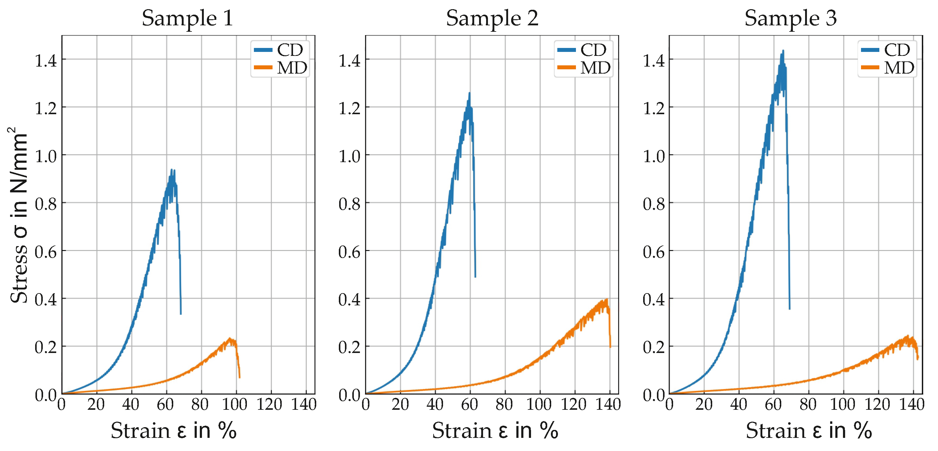
  • Young’s Modulus in machine direction (MD) and cross direction (CD) is measured with tensile test in accordance to DIN EN 29073 [8] as shown in Figure 1. For MD measurement the sample strip (width 50 mm ) is cut out so that the orientation matches the machine direction. For CD measurement the sample strip is cut out so that the orientation is perpendicular to the machine direction. Tensile tests then reveal the stress-strain-curves in both MD and CD. Young’s modulus is the average slope of the linear part of the resulting stress-strain curve. The samples exhibit linear behavior up to an elongation of 10 percent. The stress-strain curves of the samples are shown in Figure 2.
The measurement results are presented in the table below. The results are averaged for each sample.
As shown in Table 1, the nonwoven samples become denser with each needlepunch iteration due to the increase in needlepunch density. The thickness decreases, which causes the porosity to decrease. As the fabric density increases, the permeability decreases. These measurements serve as reference material for the numerical simulation. The measurements also show that the bulk properties of the nonwoven can be purposely influenced by changing the production parameters. Only a small subsection of the full parameter space available has been covered by the measurements.

3. Continuum Mechanical Description of Multiphase Anisotropic Fibrous Materials

In this work, nonwovens are treated as multiphase porous materials. A brief description of saturated porous media within a macroscopic framework is introduced in the following. This includes demonstrating the homogenization approach, the kinematics and constitutive modeling of the two-phase anisotropic material, and the governing balance relations under dynamic conditions.

3.1. Homogenization and Densities

The current work considers a biphase immiscible porous material, which consists of a materially compressible pore-fluid phase φ F (as air φ A ) and a materially-incompressible fibrous solid-phase φ S . Within the continuum mechanical modeling, homogenization is applied to representative volume elements (RVEs) in which every spatial point consists of overlapping and interacting solid and fluid constituents, i.e., φ = φ S φ F . For each constituent, a volume fraction n α is defined so that the saturation condition is always satisfied, i.e.,
α n α = n S + n F = 1 with n S : solidity , n F : porosity .
Moreover, for each constituent, we have the partial and intrinsic densities, i.e., ρ α and ρ α R , respectively, which are related through the volume fraction as ρ α = n α ρ α R .

3.2. Kinematics

The following study is restricted to the small strains framework in which the linearized strain tensor ε S of the solid phase can be expressed in terms of the gradient (∇) of the solid displacement vector u S as
ε S = 1 2 ( u S + T u S ) .
The solid motion is expressed within Lagrangean settings, whereas the air motion within Eulerian settings using the gas velocity v F = v A . Alternatively, one can utilize the seepage velocity w F : = v A v S . Thus, the material time derivative of an arbitrary vector-valued quantity ( ) and a scalar-valued quantity ( ) with respect to the motion of constituent φ α can be expressed, respectively, as
( ) α : = d α ( ) d t = ( ) t + ( ) v α , ( ) α : = d α ( ) d t = ( ) t + ( ) · v α .

3.3. Governing Balance Relations

For the given fibrous material and loading conditions, the formulations of porous media dynamics in the following are restricted to the low-frequency range. In this, a critical frequency that separates the low- and high-frequency considerations in porous media dynamics can be found in, e.g., [24,25] and relies on the micro-geometry and fluid properties of the medium. In particular, this can be expressed according to [26] as
f c r i t : = 2 η F R ρ 0 F R r 2
with r being the pore radius, η F R > 0 is the effective dynamic fluid viscosity, and ρ 0 F R is the initial material density of the fluid. Considering the material properties of air as the pore fluid and assuming the pore radius to be approximately equal to the fiber radius, i.e., r 8 μ m [1], the critical frequency is approximately f c r i t 5 × 10 5 Hz . The value of f c r i t is much higher than the considered frequencies in the numerical implementations, i.e., f e x c < 200 Hz , which justifies our treatment in the low-frequency range.
The current study also makes the following assumptions: (1) The deformations occur under isothermal conditions, (2) the airflow on the micro-scale is assumed laminar, and (3) no mass production or exchange occurs between the phases. Under these assumptions, the focus will be on the mass and momentum balances of the constituents and the overall aggregate. Moreover, the primary variables to be determined are the solid displacement u S and the pore pressure p, whereas secondary variables like the solid velocity v S = ( u S ) S , the fluid velocity v F , and the seepage velocity w F = v F v S will also be needed in the equations and computed based on the primary variables.
The mass balance of constituent φ α under the aforementioned assumptions reads
( ρ α ) α + ρ α div v α = 0 .
For the incompressible solid-phase φ S with ρ S R = const . , the solid mass balance, which yields automatically the solid volume balance, leads to an explicit relation of the solid volume fraction, expressed as
( n S ) S = n S div v S n S n 0 S S ( 1 div u S ) ,
where n 0 S S is the initial value of n S . Additionally, we proceed in the current work from the assumption of a barotropic fluid phase. Thus, a simplified relation among the fluid material density ρ F R ( p ) , the fluid compressibility κ ¯ F , and p is applied according to Borja and White [33], i.e.,
( ρ F R ) S : = ρ F R p ( p ) S = ρ F R κ ¯ F ( p ) S .
Having this together with the material time derivatives in Equation (4) and the solidity in (7), the governing fluid mass balance can be rewritten as
n F ρ F R κ ¯ F ( p ) S + ρ F R div v S + div ( ρ F R n F w F ) = 0 .
In our treatment, there is no need to explicitly compute n F w F as Darcy’s law can be incorporated in Equation (9) and, thus, the pressure gradient p will appear instead in this equation.
The momentum balance equation of constituent φ α can be expressed as
ρ α ( v α ) α = div σ α + ρ α b + p ^ α ,
where p ^ α is the volume-specific direct momentum production, which represents the local interaction force between the phases and fulfills the relation p ^ S + p ^ F = 0 . Moreover, σ α = ( σ α ) T is the symmetric partial Cauchy stress tensor and b is the mass-specific body force. In connection with the constitutive relations of the stress tensors and the momentum production term, the concept of effective stresses according to de Boer and Ehlers [34] is applied. Thus, having ( ) E as an extra or effective term, the following relations hold:
σ S = σ E S n S p I , σ F = σ E F n F p I , p ^ F = p ^ E F + p n F .
Thus, the following step is to specify the effective stress tensors. The material parameters presented in Table 1 show a clear difference in the stiffness between the machine direction (MD) and the cross direction (CD). Therefore, we adopt in this work a transversely isotropic model, discussed in, e.g., [27,35,36], for small strain problems. In this, the symmetry group MG T with the preferred fiber direction a that fulfills a = 1 , can be expressed as
MG T : = I ; Q ( θ , a ) | 0 θ 2 π .
In this, Q ( θ , a ) represents all the rotations about the a -axis. Having M : = a a as the structural tensor, the corresponding elasticity tensor can be expressed as
S C S 4 S = λ T I I + 2 μ T S I S 4 sym + α M I + I M + 2 ( μ L μ T ) S I S 4 a + β M M .
In this, the 4th-order tensor ( S I S 4 a ) i j k l can be expressed in index notations in terms of a and the Kronecker delta δ as ( I a 4 ) i j k l : = a i ( δ j k a l + δ j l a k ) + a j ( δ i l a k + δ i k a l ) , see, [27,35]. An alternative formulation of anisotropic viscoelasticity within the large strain and porous media framework can be found in, e.g., Mabuma [37]. Following this, the effective stress tensor σ E S can be expressed as
σ E S = S C S 4 S ε S .
An accurate estimation of the permeability can be carried out experimentally or via lower-scale simulations using, e.g., the Lattice Boltzmann methods (LBM) as have been thoroughly discussed in [22] among others. In connection with fibrous materials, Tamayol and Bahrami [38] studied the effects of fiber shape, orientation, and tortuosity of the medium on the permeability formulation. They concluded that the fiber alignment leads to transverse permeability for low porosities, i.e., n F < 0.7 . However, for higher porosities, this permeability is approximately isotropic. Therefore, we proceed in the current treatment from isotropic, deformation-dependent permeability, which can be expressed according to [39] as
K S : = n F n 0 S S n 0 S F n S κ K 0 S S with κ > 0 .
In this, κ is a material parameter to adjust the dependency of the permeability on the solid deformation and is considered equal 1 in this paper. The change of the permeability due to the deformation is realized through the dependency on n F , n S , and their initial values n 0 S F , n 0 S S . Having an isotropic intrinsic permeability tensor K S = K S I with K 0 S S as the initial value, the constitutive relation for the interaction force p ^ F can be expressed as
p ^ E F = ( n F ) 2 μ F R K S w F .
With regards to the fluid effective stress, many studies have shown that div σ E F p ^ F for low-viscous pore fluids, see, e.g., [28]. Thus, σ E F can be neglected from the fluid momentum balance. It is worth mentioning here that an alternative formulation of p ^ F in the high-frequency range can be found, as presented in, e.g., [26]. However, such formulations are beyond the scope of the underlying work. In the underlying treatment with air as the only pore fluid, the inertia force of air ρ A ( v A ) A , and its gravitational force ρ A b are also negligible. In summary, the governing balance relations, which are applied in the FE modeling of the nonwoven under vibration and allow to determine the primary variables { u S , p } , are
Overall momentum balance:
ρ S ( v S ) S = div ( σ E S p I ) + ρ S b + f v .
Overall mass balance:
n F ρ F R κ ¯ F ( p ) S + ρ F R div v S div ρ F R μ F R K S p = 0 .
In this, we defined in the momentum balance Equation (17) a solid viscosity-related force f v : = μ ¯ S 2 v S with 2 being the Laplace operator and μ ¯ S as a solid viscosity-related parameter, chosen equal to 0.01 in the current treatment (see also Section 4). This term is added in the sense of body force to capture the viscous-damping-induced attenuation. An explicit inclusion of the viscosity in the solid material model, as presented in [40], is beyond the scope of this work. In this connection, the presence of a viscous pore fluid leads to another source of viscous damping in the formulation. This effect is realized in the mass balance equation through the effective fluid viscosity η F R . However, this kind of damping becomes of less importance for low-viscous pore fluids like air and the case of high permeability.

4. Dynamics Analysis of Plate Vibration

In this work, the displacement field of a thin vibrating plate serves as a boundary for the nonwoven layer placed above. Before analyzing the dynamic response of the nonwoven, plate vibrations are studied separately. Free vibration modes and plate excitability are analyzed applying analytical solutions based on Kirchhoff’s plate theory, complemented by numerical solutions obtained with the FE method. At this point, an exemplary plate with suitable dimensions and boundary conditions is selected.

4.1. Mathematical Modeling

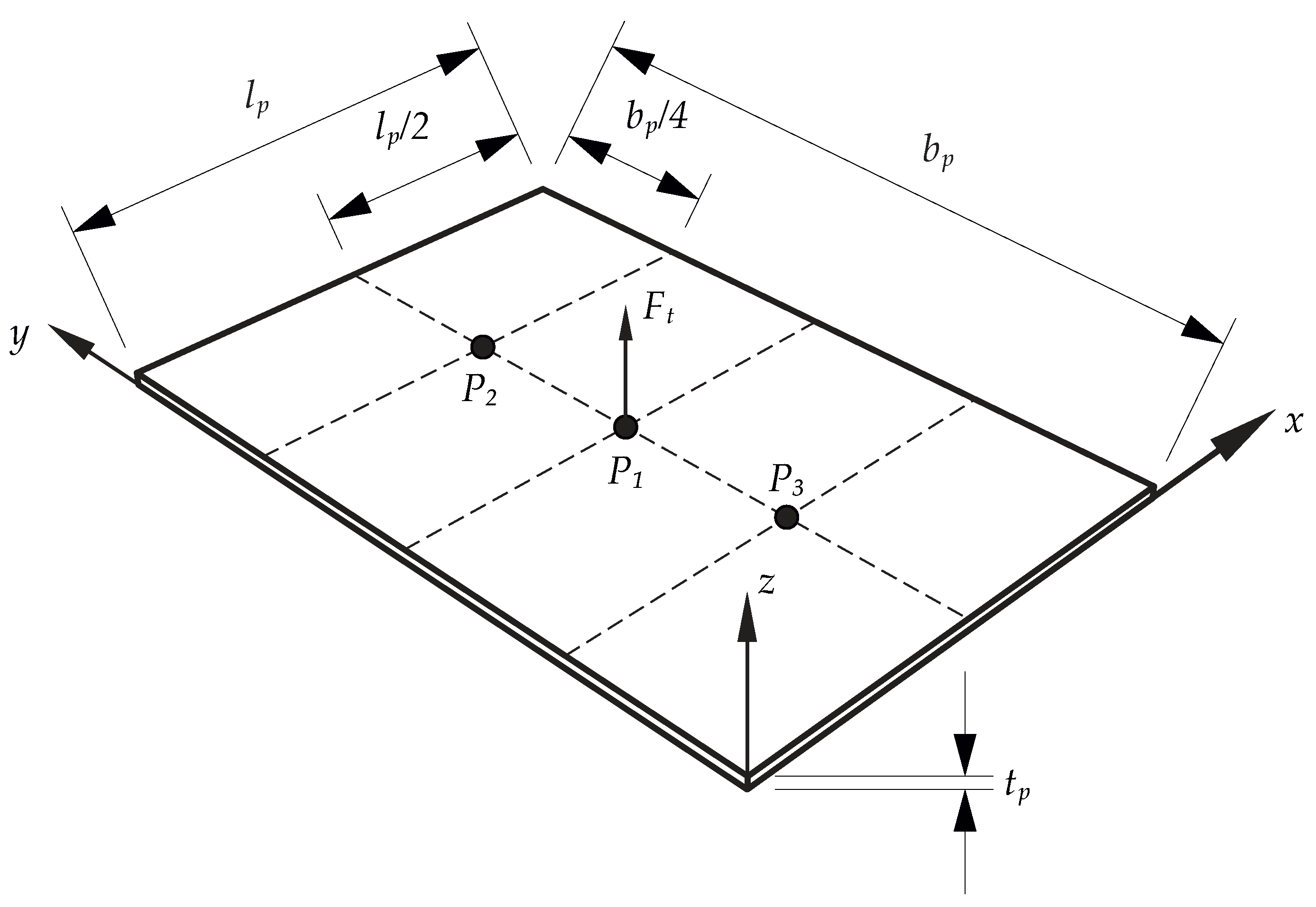
A thin plate shown in Figure 3 with parameters given in Table 2 is considered in the following.
The boundary conditions of the plate are defined such that the edges of the plate are simply supported, i.e., displacements on the edges are restricted whereas the edges can freely rotate.
For a plate with the given parameters and boundary conditions, an analytical solution of the bending vibration based on Kirchhoff’s plate theory is possible. Using the parameters introduced in Table 2, the natural angular frequencies ω ( m , n ) are
ω ( m , n ) = k m , n 2 · t p · E p 12 · ( 1 ν p 2 ) · ρ p
with
k ( m , n ) = π · ( m l p ) 2 + ( n b p ) 2 .
The integer indices m and n refer to the vibration mode and correspond to the number of vibration antinodes in x- and y-direction, respectively [15].
Steady-state solutions of vibrations excited by a concentrated harmonic force F t in the lateral direction can also be found analytically. The relation between the lateral displacement w ̲ of an arbitrary point P w on the plate and the force F ̲ t applied at an arbitrary point P F is described by the transfer mobility Y ̲ . Here, complex quantities are used to represent harmonic functions, marked by an underscore, e.g.,
F ̲ t = F ^ t · exp ( j Ω e x c t )
with F ^ t as the force magnitude, Ω e x c as the angular frequency of the excitation, and t as the time. j denotes the imaginary unit. It can be shown that the transfer mobility Y ̲ is a linear superposition of the modal transfer mobilities Y ̲ ( m , n ) , i.e.,
Y ̲ = m n Y ̲ ( m , n ) .
For a thin, simply-supported rectangular plate, the modal transfer mobility Y ̲ ( m , n ) can be calculated as
Y ̲ ( m , n ) = 4 ρ p V p · sin ( m π x w l p ) · sin ( n π y w b p ) · sin ( m π x F l p ) · sin ( n π y F b p ) ω ( m , n ) 2 Ω e x c 2 + j · 2 d ( m , n ) ω ( m , n ) Ω e x c .
In this equation, V p denotes the volume of the plate. x w and y w as well as x F and y F are the coordinates of point P w and P F , respectively. d ( m , n ) refers to the modal damping ratio, which is assumed in this case to be equal to the viscous damping ratio ξ p for each mode [15].
In addition to this analytical model, a numerical FE model of the plate is built in Abaqus/CAE 2021. With this model, free vibration mode shapes as well as time histories of the lateral displacements under force excitation are determined. The plate is meshed with eight-node shell elements (element type S8R) with an element size of 0.01 m . Material damping is modeled as Rayleigh damping, which is viscous damping proportional to the mass and stiffness of the system. Based on the global mass matrix M F E and stiffness matrix K F E , the damping matrix C F E can be calculated as
C F E = α R D M F E + β R D K F E ,
where α R D is the factor for mass-proportional damping and β R D is the factor for stiffness-proportional damping [42]. The factors are calculated such that a viscous damping ratio ξ p = 0.01 (see Table 2) is approximated in the frequency range between 50 Hz and 100 Hz [42]. This yields α R D = 4.19 1 / s and β R D = 2.12 · 10 5 s .

4.2. Numerical Analysis

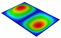
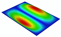
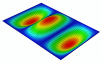
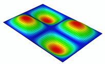
Table 3 shows the free vibration modes of the simply-supported plate with parameters from Table 2. All free vibration modes with a natural frequency below 200 Hz are listed. In the following, frequency values f will be used instead of angular frequency ω for better readability. Solutions for the natural frequencies obtained analytically and numerically using the FE method as well as the corresponding mode shapes are shown. Analytically and numerically obtained natural frequencies are very similar. Due to the selected plate dimensions and boundary conditions, the first free vibration mode has a natural frequency of about 44 Hz and one vibration antinode located in the middle of the plate. As expected, higher vibration modes exhibit an increasing natural frequency in combination with an increasing number of vibration antinodes. These results were validated through a comparison with the natural frequencies given for an exemplary plate with different but similar parameters in [15]. For this validation, the parameters of the models presented here were adjusted to match the parameters in the reference. Since the resulting natural frequencies are similar to the results in the reference, it is assumed that the results in Table 3 are reliable, too.
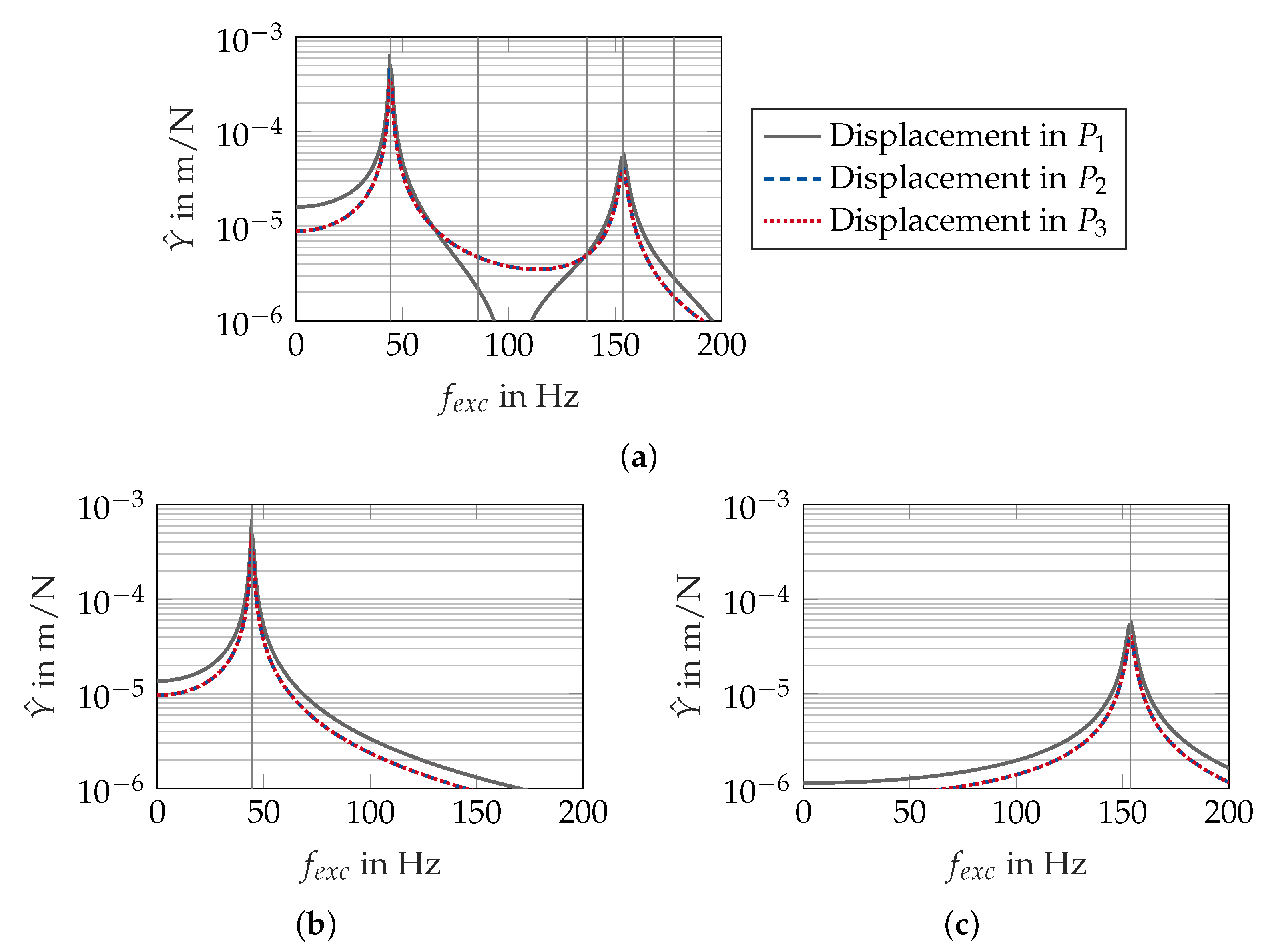
In terms of vibration excitation due to the concentrated harmonic force, the location of force application and the excitation frequency have a major influence on the resulting vibration. As mentioned before, the transfer mobility Y ̲ is a linear superposition of all transfer mobilities Y ̲ ( m , n ) of the different free vibration modes. These modes are therefore closely related to the excitability of the plate as analyzed in the following. Figure 4 shows the magnitude of the transfer mobility from a force applied at position P 1 to displacements at positions P 1 to P 3 as a function of the excitation frequency f e x c . The vertical lines mark the natural frequencies of the plate. Additionally, magnitudes of the modal transfer mobilities for mode 1 and mode 4 are shown. It is observed that the transfer mobility between 0 Hz and 200 Hz can be approximated as a superposition of the modal transfer mobilities mainly of mode 1 and 4. This corresponds to the fact that both vibration modes exhibit a vibration antinode in the point of force application (see also Table 3). In contrast, modes 2, 3, and 5 have a vibration node at this location. They cannot be excited by a force at this location, resulting in a modal transfer mobility equal to zero. Vibration modes with higher natural frequencies are negligible since they do not participate significantly on the transfer mobility Y ̲ in the frequency range up to 200 Hz . The magnitude of the transfer mobility depends strongly on the excitation frequency. As expected, resonance occurs if the excitation frequency matches the natural frequency of a mode. The magnitude of the transfer mobility exhibits local maxima at these frequencies and the vibration is strongly dominated by the corresponding free vibration mode. In contrast, antiresonance occurs at a frequency of about 100 Hz . Here, the magnitude of the transfer mobility shows a local minimum, since the modal vibrations of mode 1 and mode 4 cancel each other out due to their phase shift.
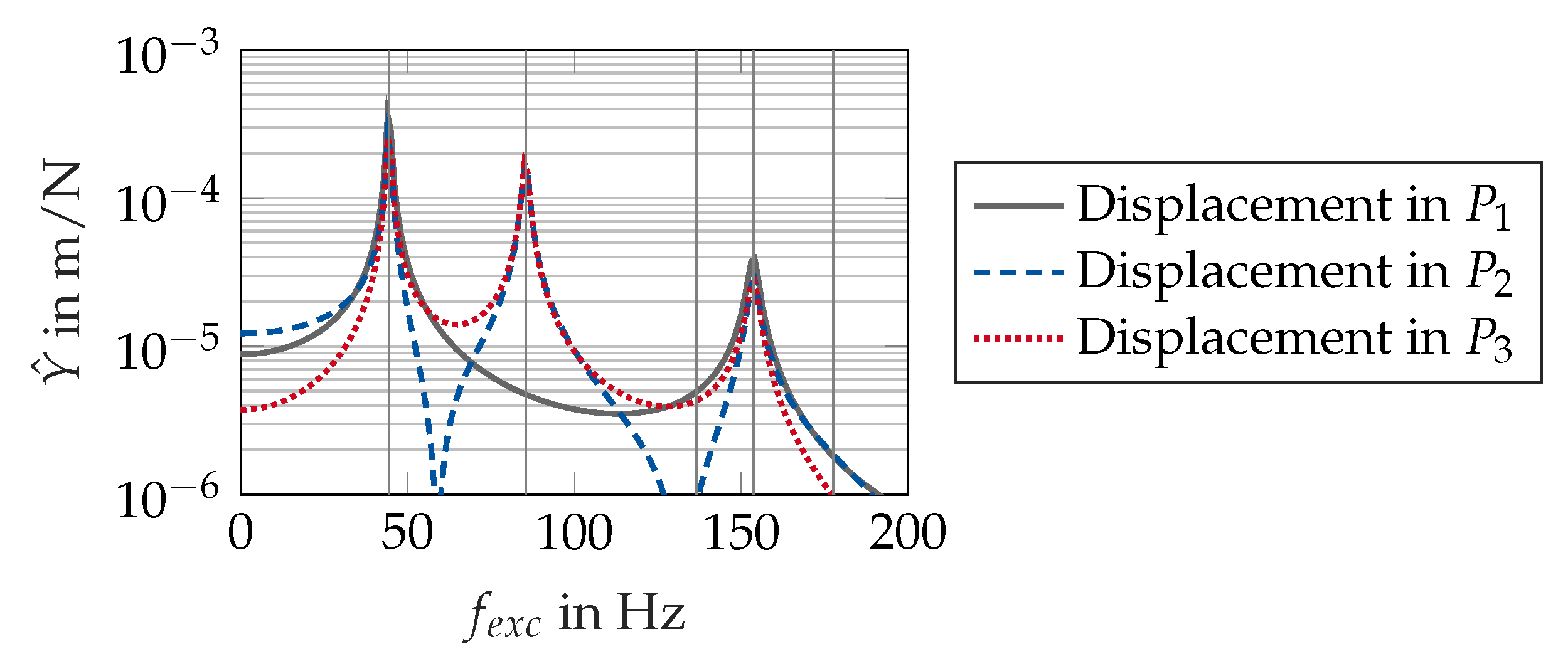
Transfer mobility for force application in point P 2 is shown in Figure 5. In contrast to force application in point P 1 , resonance occurs also at a frequency of about 85 Hz , which is the natural frequency of mode 2. At this frequency, the transfer mobility for the displacement in point P 3 has the same magnitude as for P 2 where the force is applied due to the symmetry of the involved shape modes. In contrast, this resonance does not affect the transfer mobility for the displacement in point P 1 since mode 2 has a vibration antinode at this point.
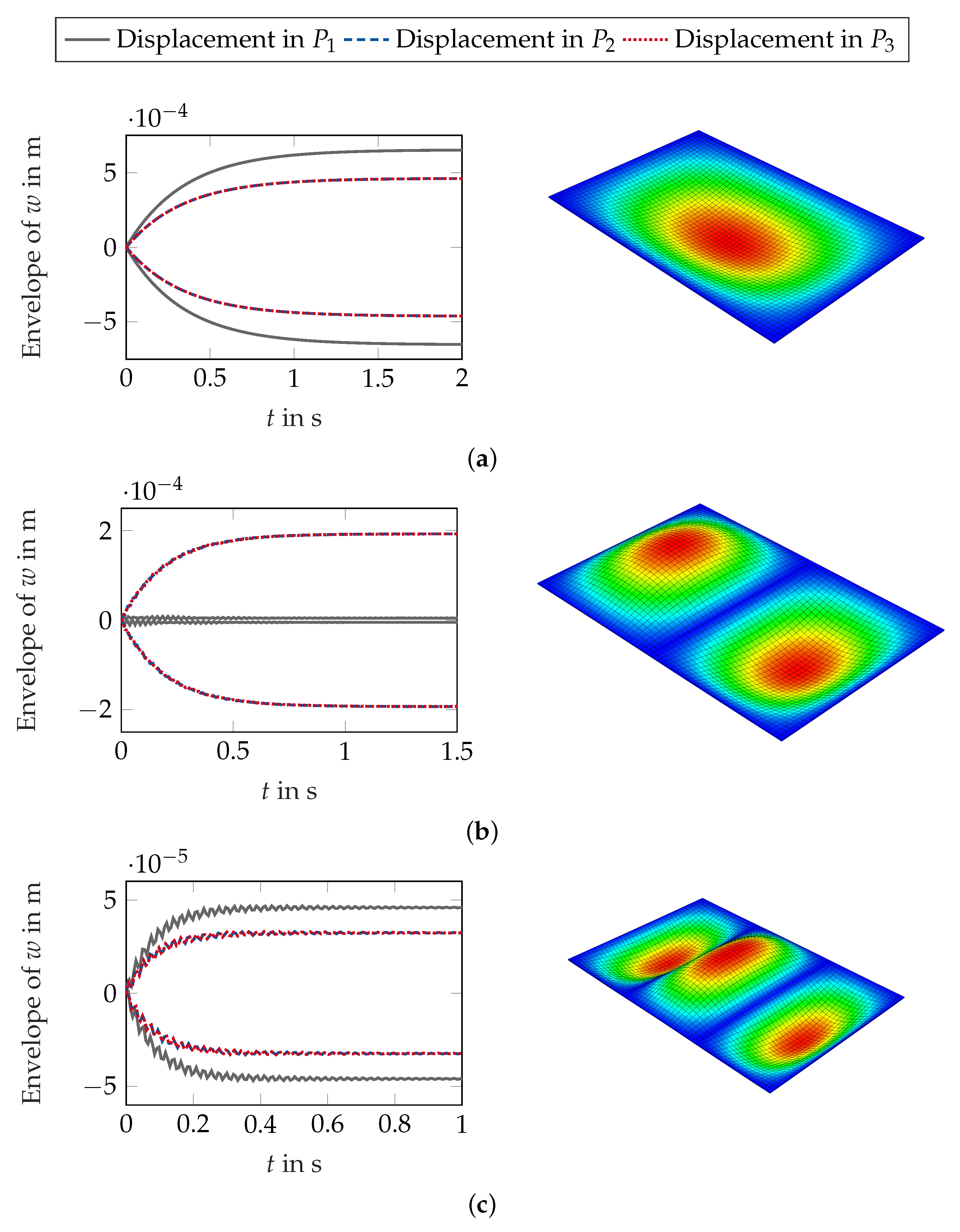
Dynamic simulations in the time domain were performed with the FE model to confirm the analytical results and to examine the transition response after the start of the force excitation. The plate was excited at the natural frequencies of mode 1, mode 2, and mode 4, respectively, whereby the point of force application was a vibration antinode of the corresponding mode (point P 1 for mode 1 and 4 as well as point P 2 for mode 2). The amplitude of the force was chosen as F ^ t = 1 N . Figure 6 shows the lateral displacement envelopes of points P 1 to P 3 as well as the vibration shape for the different excitations. Starting from the initial condition (zero displacement and velocity), the amplitudes of the vibration grow in the transition phase. After a short time, steady-state response is reached due to the material damping. Amplitudes in the steady-state are similar to the corresponding magnitudes of the transfer mobilities (see Figure 4 and Figure 5). Small deviations are caused by the fact that the viscous damping ratio ξ p = 0.01 is only approximated by the Rayleigh damping in the FE analysis.
All in all, this analysis of plate vibrations shows that the location and frequency of the excitation has a huge influence on the amplitudes and the shape of the resulting vibration. This, in turn, influences the excitation of the porous medium which is in contact with the vibrating plate. This is analyzed in the following section, considering force excitation in point P 1 at the natural frequencies of 44 Hz , 85 Hz , and 153 Hz .

5. Dynamic Response of Nonwovens as Multiphase Porous Media

The objective of the following initial-boundary-value problem (IBVP) is twofold: First, to realize the coupled hydromechanical processes in fibrous nonwovens that occur under dynamic excitation. Second, to show the effect of the applied load frequency on the coupled hydromechanical response at different locations in the domain. Therefore, we consider a three-dimensional geometry of the corresponding IBVP as illustrated in Figure 7. In this, the lower layer represents the linear elastic solid plate with material parameters and geometry discussed in Section 4 and given in Table 2. The upper layer represents the anisotropic fibrous porous domain with material parameters summarized in Table 4, which rely on the parameters that are extracted from the experiments in Table 1.
The FE implementation of the porous media coupled problem is carried out using the FE package FlexPDE (professional, ver. 7.15). In this, the Galerkin method with equal-order, linear shape functions is applied for spatial discretization using tetrahedral mesh elements. The applied time discretization is the 2nd-order implicit backward difference formula (BDF2). In this, an adaptive time-stepping scheme is used to ensure that the numerical solution remains within the specified limits of accuracy. For the solution of the non-linear PDE, a modified Newton-Raphson iteration procedure is implemented in the FlexPDE package.
In the solution of the coupled porous media problem, a monolithic approach has been implemented, which offers an unconditionally stable solution [28]. In this, the presence of a compressible pore fluid (air) allows bypassing numerical stability challenges, usually faced with incompressible fluids, as the inf–sup condition is fulfilled in this case, see, e.g., [43,44,45] for references.
A load F t = 1.0 N sin ( 2 π f e x c t ) with different frequencies, i.e., f e x c = 44, 85, 153 Hz, is considered in the analysis and applied at the center of the plate from the bottom, i.e., at coordinates (0, 0, −12.52). The relationship between the pore-air pressure and the volumetric deformations of the porous textile material can be studied based on the effective stress principle, presented in Equation (11), viz.
σ S · I = σ E S · I p I · I tr ( σ S ) = tr ( σ E S ) 3 p .
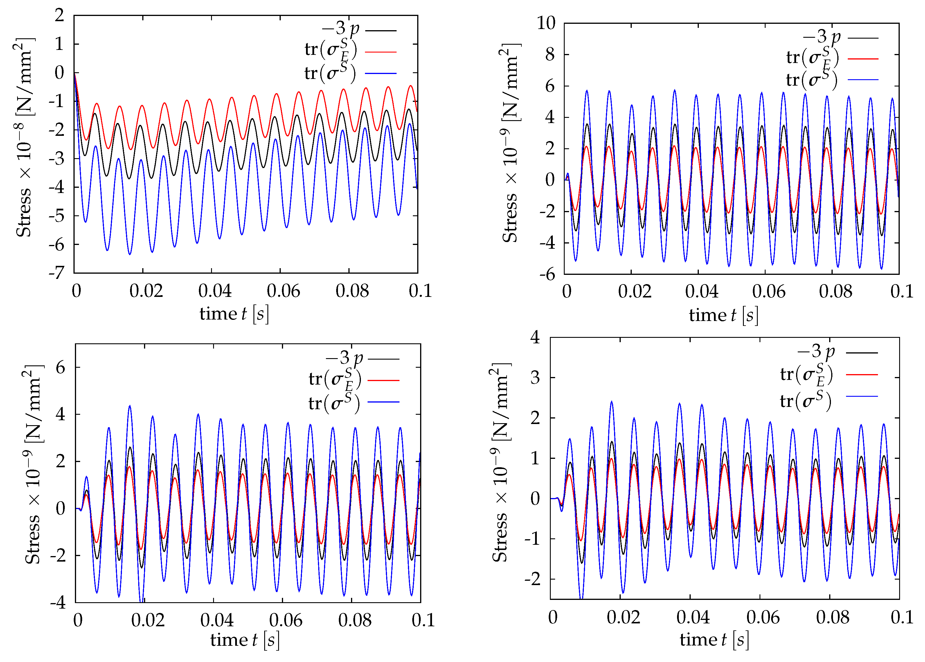
In the following, the time history of σ S , σ E S , and p at four exemplary different points, i.e., A ( 0 , 0 , 4 ) , B ( 0 , 50 , 4 ) , C ( 0 , 100 , 4 ) and D ( 0 , 150 , 4 ) , of the porous domain are investigated. These points are located above the neutral surface, where the volumetric deformations induce a significant amount of volumetric deformations and, thus, lead to increasing or decreasing in the air pressure. Particularly, Figure 8 shows the interplay between the pore-air pressure and the effective stress at all four points of the domain for the case of an excitation frequency of f e x c = 153 Hz. Of particular interest is the interaction at point A, which is located directly over the excitation point. At this point, the values of the stresses and pressure are significantly higher than that the other points in the domain. At the other points, the values of the total stress and, thus, the effective stress and the pressure are much lower.
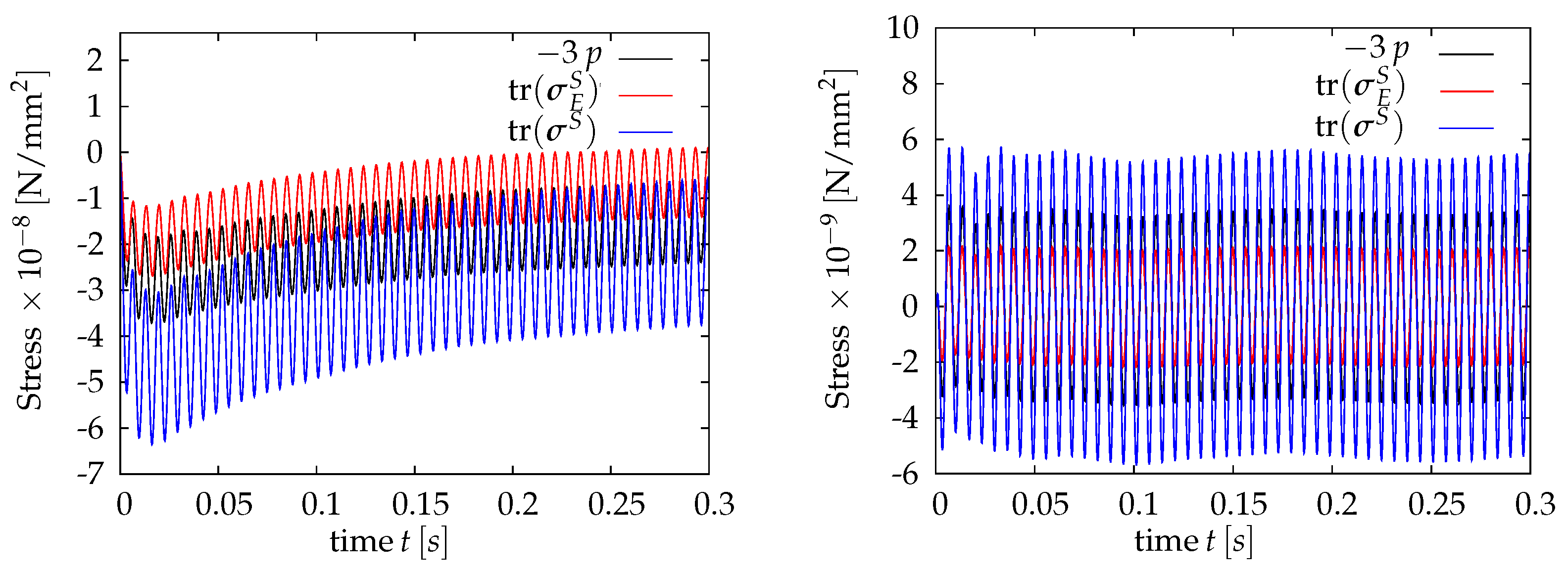
At point A of Figure 8, the negative sign of tr ( σ S ) and tr ( σ E S ) corresponds to a compaction response, which is also associated with an increase of the pore pressure. The compaction response with the negative sign of tr ( σ E S ) is associated with an increase in the normal forces between the fibers and, thus, an increase of the static friction force that is proportional to the normal one. It is worth mentioning here that at point A, the material remains under compaction also after a long time of excitation as illustrated in Figure 9, left. Moreover, it is noticeable in Figure 8 and Figure 9 that the presence of the air pressure contributes to carrying part of the load and, thus, reduces of the friction between the fibers.
Figure 8 shows that at points B, C, and D, the response changes between compaction and dilation, i.e., tr ( σ S ) and tr ( σ E S ) change between negative and positive values. The tendency of the response remains unchanged for a longer time as illustrated in Figure 9 for point B. Although the amplitude of the stresses and the pressure is much smaller than that at the location directly over the excitation point, the contribution of the air pressure (negative or positive) is significant. On the one hand, the positive pressure (notice that 3 p is plotted) reduces the compaction and, thus, obstructs the increase of the static friction force. On the other hand, the negative pressure (suction effect) reduces the dilation effect and, thus, obstructs the reduction of the static friction force.
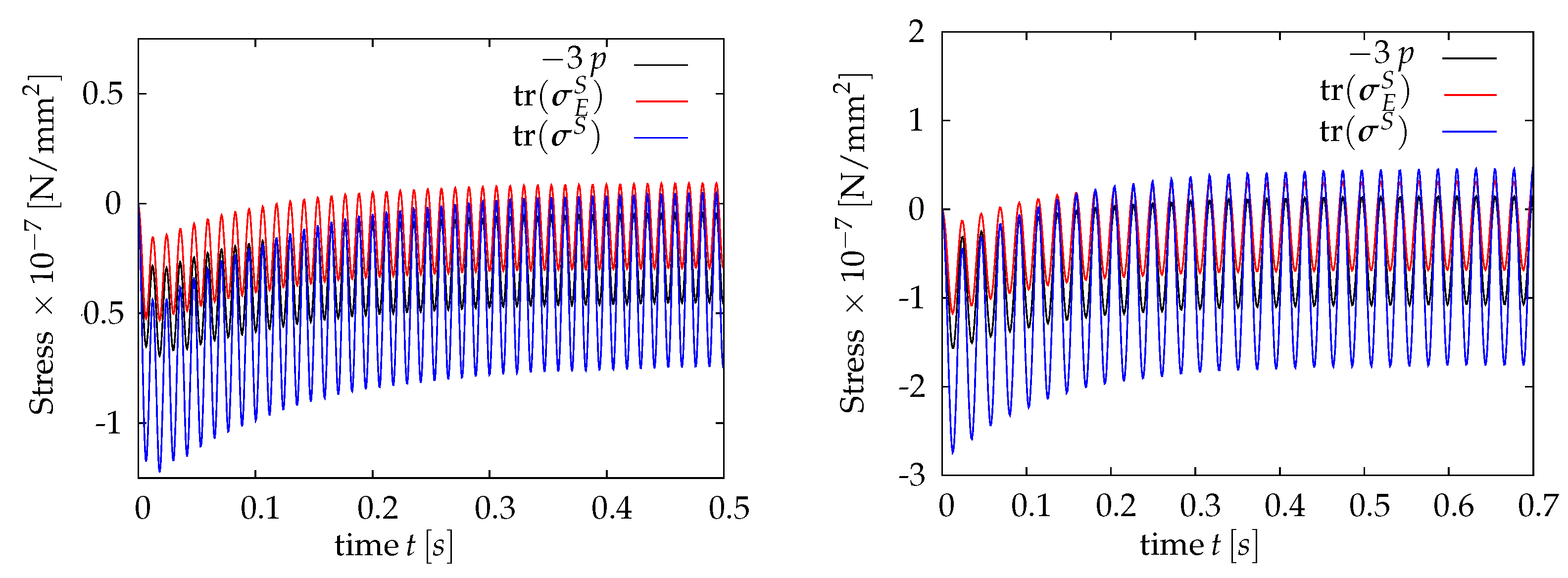
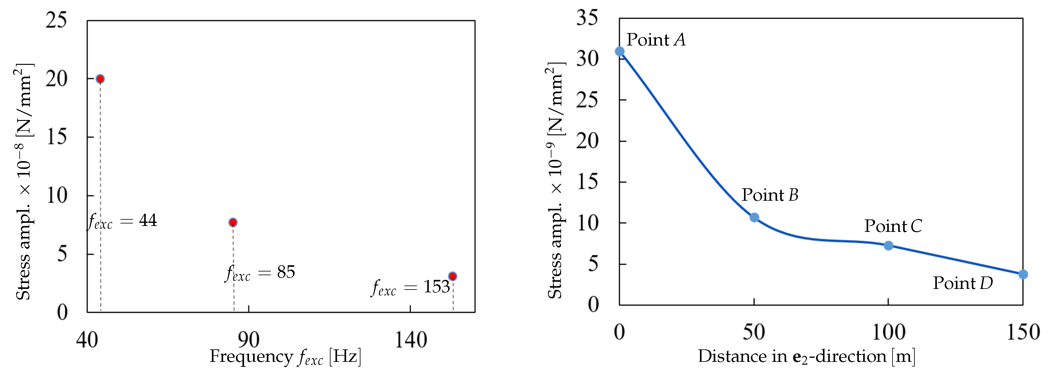
Looking at the other cases of excitation, i.e., for f e x c = 85 Hz and f e x c = 44 Hz depicted in Figure 10 for point A, the same conclusion can be drawn about the contribution of the pore pressure to carrying a significant part of the applied stresses and, thus, affecting the values of the friction forces between the fibers. In this, at the beginning of the excitation, a larger amplitude of tr ( σ S ) is obtained, which is reduced after each cycle until reaching a steady-state response. In connection with the effect of the excitation frequency on the response, the results presented in Figure 9 and Figure 10 show that the lower the frequency of the excitation, the higher is the value of the resulting total solid stress tr ( σ S ) and, thus, the deformation. This effect is illustrated in Figure 11, left, for the three considered frequencies. It is also noticeable that the change of the material response over the excitation point from compaction to dilation is reached for lower frequency excitation but not for the higher frequency, as for f e x c = 153 Hz.
With regards to quantifying the damping effects during wave propagation in the porous medium layer, the obtained results show a reduction of the maximum amplitude of tr ( σ S ) by approx. 85 % from point A to point D. This wave amplitude attenuation is also illustrated in Figure 11, right, for four points ( A , B , C , D ) in the domain.

6. Conclusions and Future Aspects

In this research work, we presented a holistic study related to the dynamic response of nonwovens. This included the characterization of the properties of the nonwoven materials using laboratory experiments and samples with different initial states, a dynamic analysis of a thin vibrating plate, which represents a base for the fibrous textile layer, and a numerical simulation of nonwovens as multiphase anisotropic porous media.
The Theory of Porous Media was used for the continuum-mechanical description of the anisotropic porous medium, whereas the formulations considered two phases, i.e., solid and air phases. In this, we restricted the modeling to isothermal and small strain conditions. The formulations adopted a deformation-dependent permeability and considered the damping effect of the solid material in the sense of a body force. Another source of damping in the mechanical response resulted from the flow of the viscous fluid (air) in the porous textile domain. The resulting coupled PDEs were then solved numerically using a monolithic approach in the FEM package FlexPDE.
The material parameters in the FE model of the dynamic response of nonwovens as multiphase porous media are based on the experiments carried out within this research project. The geometry of the vibrating plate and the excitation frequencies are based on a dynamics analysis of plate vibration. Plate vibration, excited by concentrated harmonic forces, was analyzed using transfer mobilities. It was shown that vibration shape and amplitude strongly depend on the location and frequency of the force excitation. As expected, the highest amplitudes occur if a free vibration mode is excited at its natural frequency. Results were confirmed by dynamic simulations of an FE model. Different excitations at the plate’s natural frequencies were selected for the analysis of the porous medium.
The numerical results showed the capability of the proposed model in realizing the interaction between the pore-air pressure and the effective stresses during nonwovens vibration. In particular, the role of the pore air in vibration-induced friction reduction during material compaction was evident. On the contrary, the negative pressure (suction effect) resulted in a reduction of material dilation and, thus, obstructed the static friction force reduction during vibration. The numerical results allowed also to show and measure the damping effects during wave propagation in the nonwovens layer. It was also remarkable from the numerical results that the change of the material response in the region over the excitation point from compaction to dilation is reachable only for the lower frequency excitation and not for higher frequency. In this regard, for the same amplitude of the excitation, the lower the frequency the higher is the value of the resulting total solid stress and, thus, the volumetric deformations.
Our work is a first step towards understanding the mechanisms inside a nonwoven as a porous medium when excited by an imposed displacement. Understanding the thermal, viscous and mechanical effects inside the medium could lead towards a model that predicts its energy dissipation capabilities. The predictive model helps engineers to design the right material for a given sound insulation task. Our work shows that there are many questions remaining if one wants to build such a predictive model.
Several important aspects and open questions need to be addressed in our future works. This includes the application of lower-scale simulations, such as the lattice Boltzmann method (LBM), to representative volume elements (RVEs) to determine quantities like the intrinsic permeability. It is also important to study in future works the effect of excitation location and boundary conditions on the response. Additionally, finding a correlation between the eigenmodes of the vibrating plate and the hydro-mechanical response of the nonwovens is one of the remaining open topics.

Author Contributions

Conceptualization, J.-L.A., R.K. and Y.H.; methodology, J.-L.A., R.K., Y.H., F.C., B.M., T.G. and B.C.; software, J.-L.A. and Y.H.; writing—original draft preparation, J.-L.A., R.K. and Y.H.; writing—review and editing, F.C., B.M., T.G. and B.C. All authors have read and agreed to the published version of the manuscript.

Funding

This research received no external funding.

Institutional Review Board Statement

Not applicable.

Informed Consent Statement

Not applicable.

Data Availability Statement

The data presented in this study are available on request from the corresponding authors.

Conflicts of Interest

The authors declare no conflict of interest.

References

  1. Soltani, P.; Norouzi, M. Prediction of the sound absorption behavior of nonwoven fabrics: Computational study and experimental validation. J. Sound Vib. 2020, 485, 115607. [Google Scholar] [CrossRef]
  2. Wilson, A. Development of the nonwovens industry. In Handbook of Nonwovens; Russell, S.J., Ed.; Woodhead Publishing Series in textiles; CRC Press: Boca Raton, FL, USA, 2007; pp. 1–16. [Google Scholar]
  3. Shoshani, Y.; Yakubov, Y. A Model for Calculating the Noise Absorption Capacity of Nonwoven Fiber Webs. Text. Res. J. 1999, 69, 519–526. [Google Scholar] [CrossRef]
  4. Zarek, J. Sound absorption in flexible porous materials. J. Sound Vib. 1978, 61, 205–234. [Google Scholar] [CrossRef]
  5. Yang, S.; Yu, W.; Pan, N. Investigation of the sound-absorbing behavior of fiber assemblies. Text. Res. J. 2011, 81, 673–682. [Google Scholar] [CrossRef]
  6. Beier, H.; Vogel, C.; Haase, J.; Hunger, M.; Schmalz, E.; Sauerkunze, M.; Bergmann, L. Vliesstoffe für technische Anwendungen. In Vliesstoffe; Fuchs, H., Albrecht, W., Eds.; Wiley-VCH: Weinheim, Germany, 2012. [Google Scholar]
  7. DIN Deutsches Institut für Normung e.V. DIN EN ISO 9053-1: Akustik-Bestimmung des Strömungswiderstands: Teil 1: Verfahren mit statischer Luftströmung; Beuth Verlag GmbH: Berlin, Germany, 2019. [Google Scholar]
  8. DIN Deutsches Institut für Normung e.V. DIN EN 29 073: Prüfverfahren für Vliesstoffe: Bestimmung der Höchstzugkraft und Höchstzugkraftdehnung; Beuth Verlag GmbH: Berlin, Germany, 1992. [Google Scholar]
  9. Banerjee, M.M.; Mazumdar, J. A Review of Methods for Linear and Nonlinear Vibration Analysis of Plates and Shells. Procedia Eng. 2016, 144, 493–503. [Google Scholar] [CrossRef] [Green Version]
  10. Ahad, F.E.; Shi, D.Y. Analytical Approaches to Vibration Analysis of Thick Plates Subjected to Different Supports, Loadings and Boundary Conditions—A Literature Survey. Int. J. Eng. Res. Afr. 2015, 17, 43–53. [Google Scholar] [CrossRef]
  11. Ton-That, H.L.; Nguyen-Van, H.; Chau-Dinh, T. An Improved Four-Node Element for Analysis of Composite Plate/Shell Structures Based on Twice Interpolation Strategy. Int. J. Comput. Methods 2020, 17, 1950020. [Google Scholar] [CrossRef]
  12. Ton-That, H.L.; Nguyen-Van, H. A Combined Strain Element in Static, Frequency and Buckling Analyses of Laminated Composite Plates and Shells. Period. Polytech. Civ. Eng. 2021, 65, 56–71. [Google Scholar] [CrossRef]
  13. Phung, M.V.; Nguyen, D.T.; Doan, L.T.; Nguyen, D.V.; Duong, T.V. Numerical Investigation on Static Bending and Free Vibration Responses of Two-Layer Variable Thickness Plates with Shear Connectors. Iran. J. Sci. Technol. Trans. Mech. Eng. 2022, 1–19. [Google Scholar] [CrossRef]
  14. Ton-That, H.L.; Nguyen-Van, H.; Chau-Dinh, T. A novel quadrilateral element for analysis of functionally graded porous plates/shells reinforced by graphene platelets. Arch. Appl. Mech. 2021, 91, 2435–2466. [Google Scholar] [CrossRef]
  15. Zeller, P. Handbuch Fahrzeugakustik: Grundlagen, Auslegung, Berechnung, Versuch, 2nd ed.; ATZ/MTZ-Fachbuch, Vieweg+Teubner Verlag: Wiesbaden, Germany, 2012. [Google Scholar]
  16. Ramu, I.; Mohanty, S.C. Study on Free Vibration Analysis of Rectangular Plate Structures Using Finite Element Method. Procedia Eng. 2012, 38, 2758–2766. [Google Scholar] [CrossRef] [Green Version]
  17. Isanaka, B.R.; Akbar, M.A.; Mishra, B.P.; Kushvaha, V. Free vibration analysis of thin plates: Bare versus Stiffened. Eng. Res. Express 2020, 2, 015014. [Google Scholar] [CrossRef]
  18. Ehlers, W. Foundations of multiphasic and porous materials. In Porous Media: Theory, Experiments and Numerical Applications; Ehlers, W., Bluhm, J., Eds.; Springer: Berlin/Heidelberg, Germany, 2002; pp. 3–86. [Google Scholar]
  19. Markert, B. A constitutive approach to 3-d nonlinear fluid flow through finite deformable porous continua. Transp. Porous Media 2007, 70, 427. [Google Scholar] [CrossRef]
  20. Heider, Y.; Avci, O.; Markert, B.; Ehlers, W. The dynamic response of fluid-saturated porous materials with application to seismically induced soil liquefaction. Soil Dyn. Earthq. Eng. 2014, 63, 120–137. [Google Scholar] [CrossRef]
  21. Ehlers, W.; Wagner, A. Modelling and simulation methods applied to coupled problems in porous-media mechanics. Arch. Appl. Mech. 2019, 89, 609–628. [Google Scholar] [CrossRef]
  22. Chaaban, M.; Heider, Y.; Markert, B. Upscaling LBM-TPM simulation approach of Darcy and non-Darcy fluid flow in deformable, heterogeneous porous media. Int. J. Heat Fluid Flow 2020, 83, 108566. [Google Scholar] [CrossRef]
  23. Heider, Y. Multi-Field and Multi-Scale Computational Fracture Mechanics and Machine-Learning Material Modeling; Habilitation, Report No. 13 of Institute of General Mechanics; RWTH Aachen University: Aachen, Germany, 2021. [Google Scholar] [CrossRef]
  24. Biot, M. Theory of propagation of elastic waves in a fluid-saturated porous solid. II. High-frequency range. J. Acoust. Soc. Am. 1956, 28, 179–191. [Google Scholar] [CrossRef]
  25. Biot, M. Theory of propagation of elastic waves in a fluid-saturated porous solid I. Low-frequency range. J. Acoust. Soc. Am. 1956, 28, 168–178. [Google Scholar] [CrossRef]
  26. Steeb, H. Ultrasound propagation in cancellous bone. Arch. Appl. Mech. 2010, 80, 489–502. [Google Scholar] [CrossRef]
  27. Schröder, J. Theoretische und algorithmische Konzepte zur phänomenologischen Beschreibung anisotropen Materialverhaltens. Ph.D. Thesis, Inst. f. Baumechanik u. Numerische Mechanik, Universität Hannover, Hanover, Germany, 1996. [Google Scholar]
  28. Markert, B.; Heider, Y.; Ehlers, W. Comparison of monolithic and splitting solution schemes for dynamic porous media problems. Int. J. Numer. Methods Eng. 2010, 82, 1341–1383. [Google Scholar] [CrossRef]
  29. Heider, Y. Saturated Porous Media Dynamics with Application to Earthquake Engineering. Ph.D. Thesis, Institute of Applied Mechanics (CE), University of Stuttgart, Stuttgart, Germany, 2012. [Google Scholar]
  30. Markert, B. A survey of selected coupled multifield problems in computational mechanics. J. Coupled Syst. Multiscale Dyn. 2013, 1, 22–48. [Google Scholar] [CrossRef]
  31. Padilla, C.A.; Patil, S.P.; Heider, Y.; Markert, B. 3D modelling of brittle fracture using a joint all-atom and phase-field approach. GAMM Mitteilungen 2017, 40, 91–101. [Google Scholar] [CrossRef]
  32. Ali, B.; Heider, Y.; Markert, B. Residual stresses in gas tungsten arc welding: A novel phase-field thermo-elastoplasticity modeling and parameter treatment framework. Comput. Mech. 2021, 69, 565–587. [Google Scholar] [CrossRef]
  33. Borja, R.I.; White, J.A. Conservation Laws for Coupled Hydro-Mechanical Processes in Unsaturated Porous Media. In Mechanics of Unsaturated Geomaterials; Wiley-Blackwell: Hoboken, NJ, USA, 2013; Volume Chapter 8, pp. 185–208. [Google Scholar]
  34. de Boer, R.; Ehlers, W. The development of the concept of effective stresses. Acta Mech. 1990, 83, 77–92. [Google Scholar] [CrossRef]
  35. Heider, Y.; Wang, K.; Sun, W. SO(3)-invariance of informed-graph-based deep neural network for anisotropic elastoplastic materials. Comput. Methods Appl. Mech. Eng. 2020, 363, 112875. [Google Scholar] [CrossRef]
  36. Heider, Y.; Bamer, F.; Ebrahem, F.; Markert, B. Self-organized criticality in fracture models at different scales. Examples Counterexamples 2022, 2, 100054. [Google Scholar] [CrossRef]
  37. Mabuma, J. Multi-Field Modelling and Simulation of the Human Hip Joint. Ph.D. Thesis, Institute of Applied Mechanics (CE), University of Stuttgart, Stuttgart, Germany, 2014. [Google Scholar]
  38. Tamayol, A.; Bahrami, M. Transverse permeability of fibrous porous media. Phys. Rev. E Stat. Nonlinear Soft Matter Phys. 2011, 83, 046314. [Google Scholar] [CrossRef] [Green Version]
  39. Markert, B. A biphasic continuum approach for viscoelastic high-porosity foams: Comprehensive theory, numerics, and application. Arch. Comput. Methods Eng. 2008, 15, 371–446. [Google Scholar] [CrossRef]
  40. Beckmann, A.; Heider, Y.; Stoffel, M.; Markert, B. Assessment of the viscoelastic mechanical properties of polycarbonate urethane for medical devices. J. Mech. Behav. Biomed. Mater. 2018, 82, 1–8. [Google Scholar] [CrossRef]
  41. Orban, F. Damping of materials and members in structures. J. Phys. Conf. Ser. 2011, 268, 012022. [Google Scholar] [CrossRef]
  42. Rahul, B.; Dharani, J.; Balaji, R. Optimal Method for Determination of Rayleigh Damping Coefficients for Different Materials using Modal Analysis. Int. J. Veh. Struct. Syst. 2021, 13. [Google Scholar] [CrossRef]
  43. Sweidan, A.H.; Heider, Y.; Markert, B. A unified water/ice kinematics approach for phase-field thermo-hydro-mechanical modeling of frost action in porous media. Comput. Methods Appl. Mech. Eng. 2020, 372, 113358. [Google Scholar] [CrossRef]
  44. Sweidan, A.; Niggemann, K.; Heider, Y.; Ziegler, M.; Markert, B. Experimental study and numerical modeling of the thermo-hydro-mechanical processes in soil freezing with different frost penetration directions. Acta Geotech. 2022, 17, 231–255. [Google Scholar] [CrossRef]
  45. Heider, Y. A review on phase-field modeling of hydraulic fracturing. Eng. Fract. Mech. 2021, 253, 107881. [Google Scholar] [CrossRef]
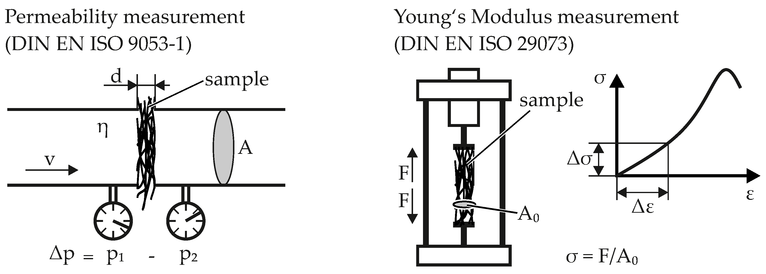
Figure 1. Measurement of permeability and elasticity modulus.
Applmech 03 00029 g001
Figure 2. Strain-stress curves for all samples obtained from tensile test.
Applmech 03 00029 g002
Figure 3. Model of the vibrating plate with its dimensions, characteristic points P 1 to P 3 for displacement evaluation and force application as well as an exemplary force F t .
Applmech 03 00029 g003
Figure 4. Magnitudes Y ^ of the transfer mobility for force application in P 1 as a function of the excitation frequency f e x c : (a) (Overall) transfer mobility; (b) Modal transfer mobility of mode 1; (c) Modal transfer mobility of mode 4.
Applmech 03 00029 g004
Figure 5. Magnitudes Y ^ of the transfer mobility for force application in P 2 as a function of the excitation frequency f e x c .
Applmech 03 00029 g005
Figure 6. Envelope of the lateral displacement w in points P 1 to P 3 and vibration shapes for different excitations: (a) Excitation in P 1 with 44 Hz ; (b) Excitation in P 2 with 85 Hz ; (c) Excitation in P 1 with 153 Hz .
Applmech 03 00029 g006
Figure 7. Geometry and boundary conditions of the porous media dynamics model, consisting of a lower plate and an upper textile layer. At the upper boundary, p ¯ = 0 (drained), whereas an excitation force F t is applied at the lower boundary of the plate at its center. The side boundaries are fixed in all directions, drained, and the preferred direction of anisotropy is a : = e 2 .
Applmech 03 00029 g007
Figure 8. Total solid stress, solid effective stress, and pore-pressure changes over the time range [ 0 , 0.1 ] s at points A (top-left), B (top-right), C (bottom-left), and D (bottom-right) of the domain for the case of an excitation frequency of f e x c = 153 Hz.
Applmech 03 00029 g008
Figure 9. Total solid stress, solid effective stress, and pore-pressure changes over the time range [ 0 , 0.3 ] s at point A (left) and point B (right) for the case of excitation frequency f e x c = 153 Hz.
Applmech 03 00029 g009
Figure 10. Total solid stress, effective solid stress, and pore-pressure changes over the time range [ 0 , 0.5 ] s at point A for the case of an excitation frequency f e x c = 85 Hz (left) and over the time range [ 0 , 0.7 ] s for f e x c = 44 Hz (right).
Applmech 03 00029 g010
Figure 11. Illustration of the maximum reached amplitude of tr ( σ S ) at point A for the three different excitation amplitudes f e x c (left). Illustration of attenuation of the maximum amplitude of tr ( σ S ) as getting far from the point of excitation for f e x c = 153 Hz and in the steady-state (right).
Applmech 03 00029 g011
Table 1. Experimental measurements of the material properties of the nonwovens.
QuantityUnitSample 1Sample 2Sample 3
Needlepunch iterations 123
Thickness t mm 10.52 6.17 5.66
Weight per area A g / m 2 242.79 248.29 265.65
Permeability K 0 mm 2 0.002456 0.001284 0.001071
Elasticity modulus MD E T N / mm 2 0.0638 0.0605 0.0747
Elasticity modulus CD E L N / mm 2 0.2208 0.2898 0.3201
Porosity n F - 0.9757 0.9576 0.9506
Table 2. Parameters of the plate.
QuantityUnitValue
Dimensions:
Length l p mm 400
Width b p mm 600
Thickness t p mm 2
Material Parameters (Steel):
Density ρ p kg / m 3 7850
Elasticity modulus E p N / mm 2 210,000
Poisson’s ratio ν p - 0.3
Viscous damping ratio ξ p [41]- 0.01
Table 3. Free vibration modes with natural frequencies f ( m , n ) below 200 Hz .
Mode f ( m , n ) in Hz f ( m , n ) in Hz Mode Shape
(Analytical)(FE)(FE)
Mode 1 ( m = 1 , n = 1 ) 44.391 44.318 Applmech 03 00029 i001
Mode 2 ( m = 1 , n = 2 85.367 85.211 Applmech 03 00029 i002
Mode 3 ( m = 2 , n = 1 ) 136.59 136.47 Applmech 03 00029 i003
Mode 4 ( m = 1 , n = 3 ) 153.66 153.44 Applmech 03 00029 i004
Mode 5 ( m = 2 , n = 2 ) 177.56 177.24 Applmech 03 00029 i005
Table 4. Parameters for the multiphase textile material, which rely on sample 1 in Table 1.
QuantityUnitValue
Dimensions (textile layer):
Length l p m mm 400
Width b p m mm 600
Thickness t p m mm 10.52
Material Parameters (textile material):
Solid material density ρ S R kg / m 3 1500
Elasticity modulus in MD ( E T ) N / mm 2 0.0638
Elasticity modulus in CD ( E L ) N / mm 2 0.2208
Poisson’s ratio ν S - 0.3
1st Lamé parameter in MD ( μ T ) N / mm 2 0.0245
2nd Lamé parameter in MD ( λ T ) N / mm 2 0.037
1st Lamé parameter in CD ( μ L ) N / mm 2 0.16
initial porosity n 0 S A 0.976
Fluid (air) material density ρ A R kg / m 3 1.2
Effective dynamic fluid viscosity η A R Ns / mm 2 18.1
Initial intrinsic permeability K 0 S mm 2 0.0002456
Permeability-related parameter κ 1
Publisher’s Note: MDPI stays neutral with regard to jurisdictional claims in published maps and institutional affiliations.