A 3D-Printed Honeycomb Cell Geometry Design with Enhanced Energy Absorption under Axial and Lateral Quasi-Static Compression Loads

 , ,
, , 
Abstract
:1. Introduction
2. Materials and Methods
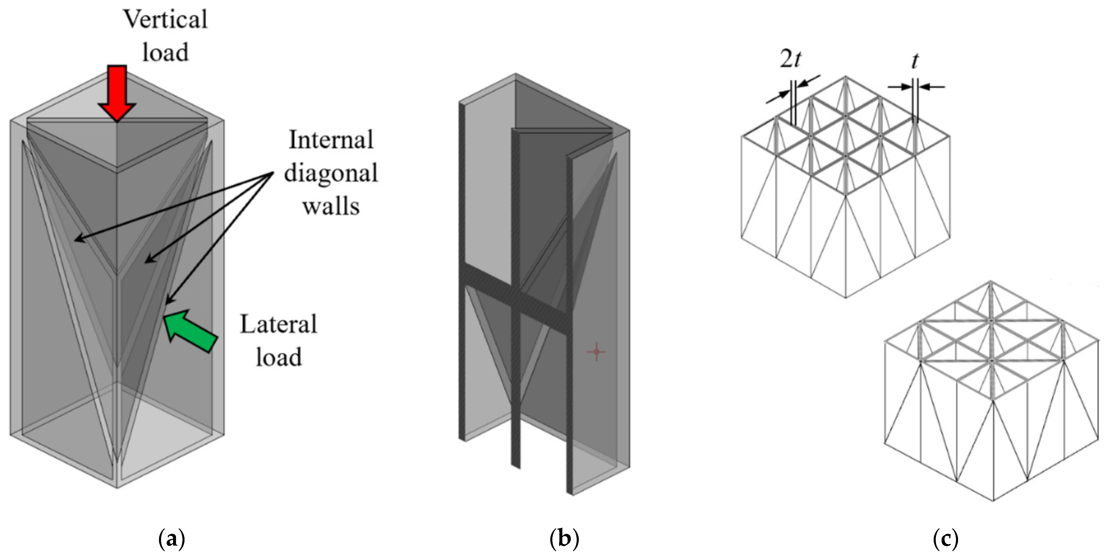
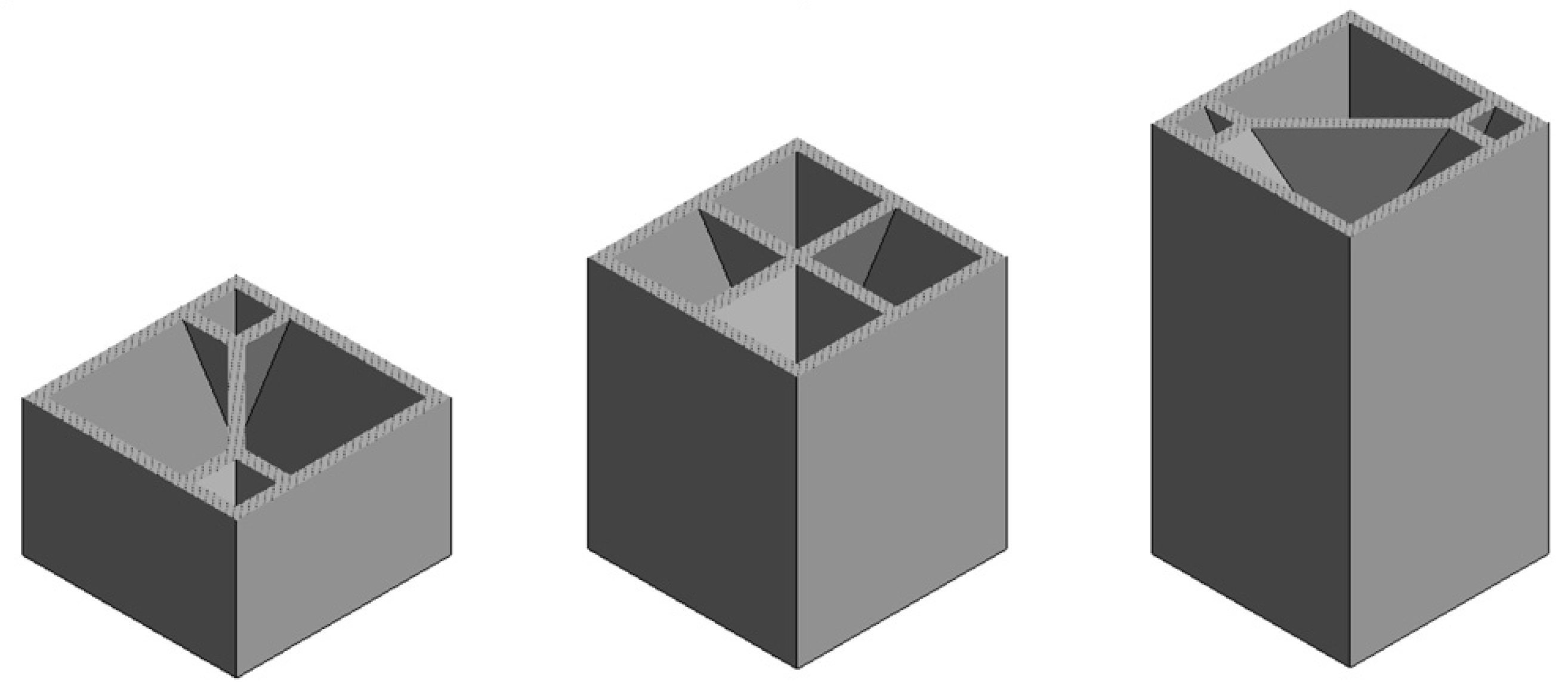
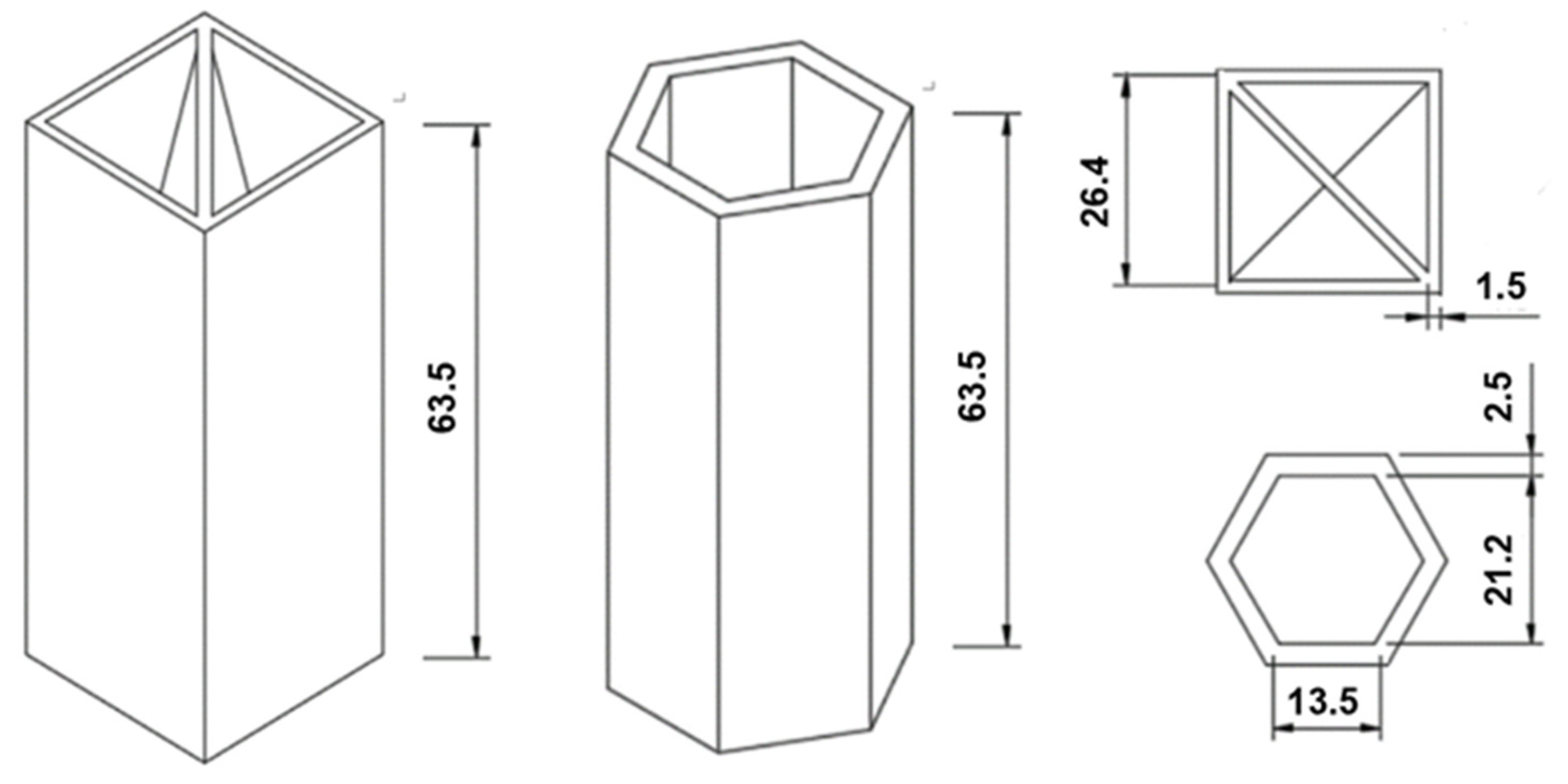
2.1. Cell Geometry Design
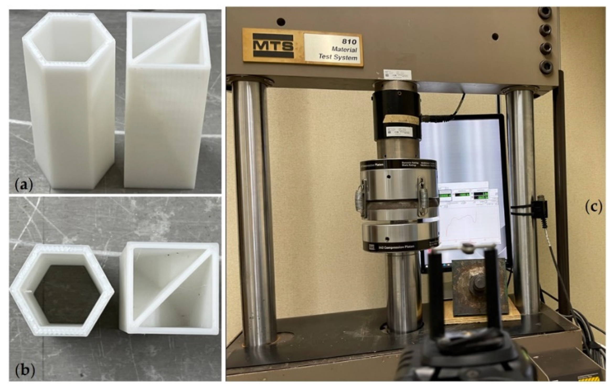
2.2. Materials and Fabrication
2.3. Experimental Setup
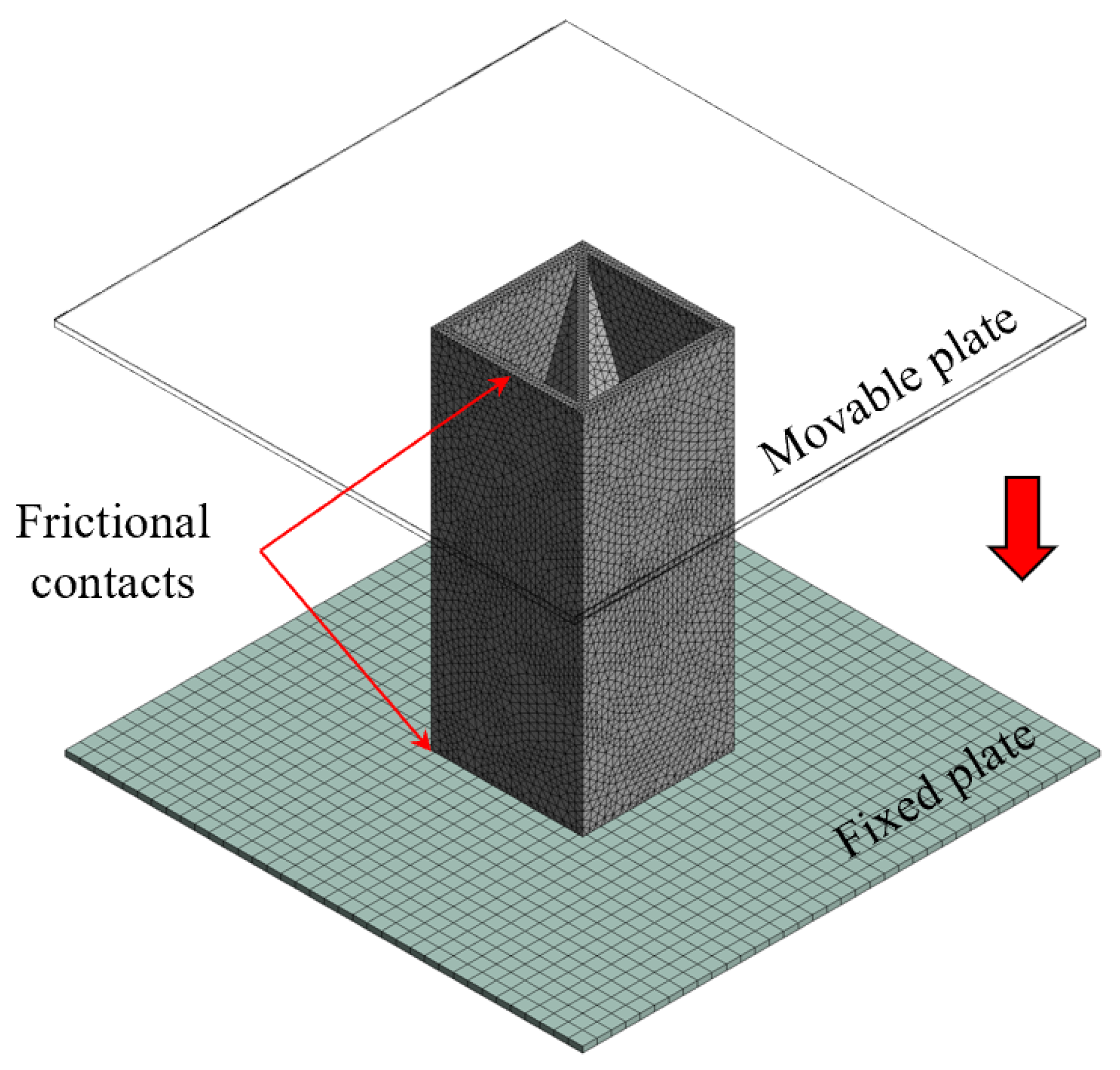
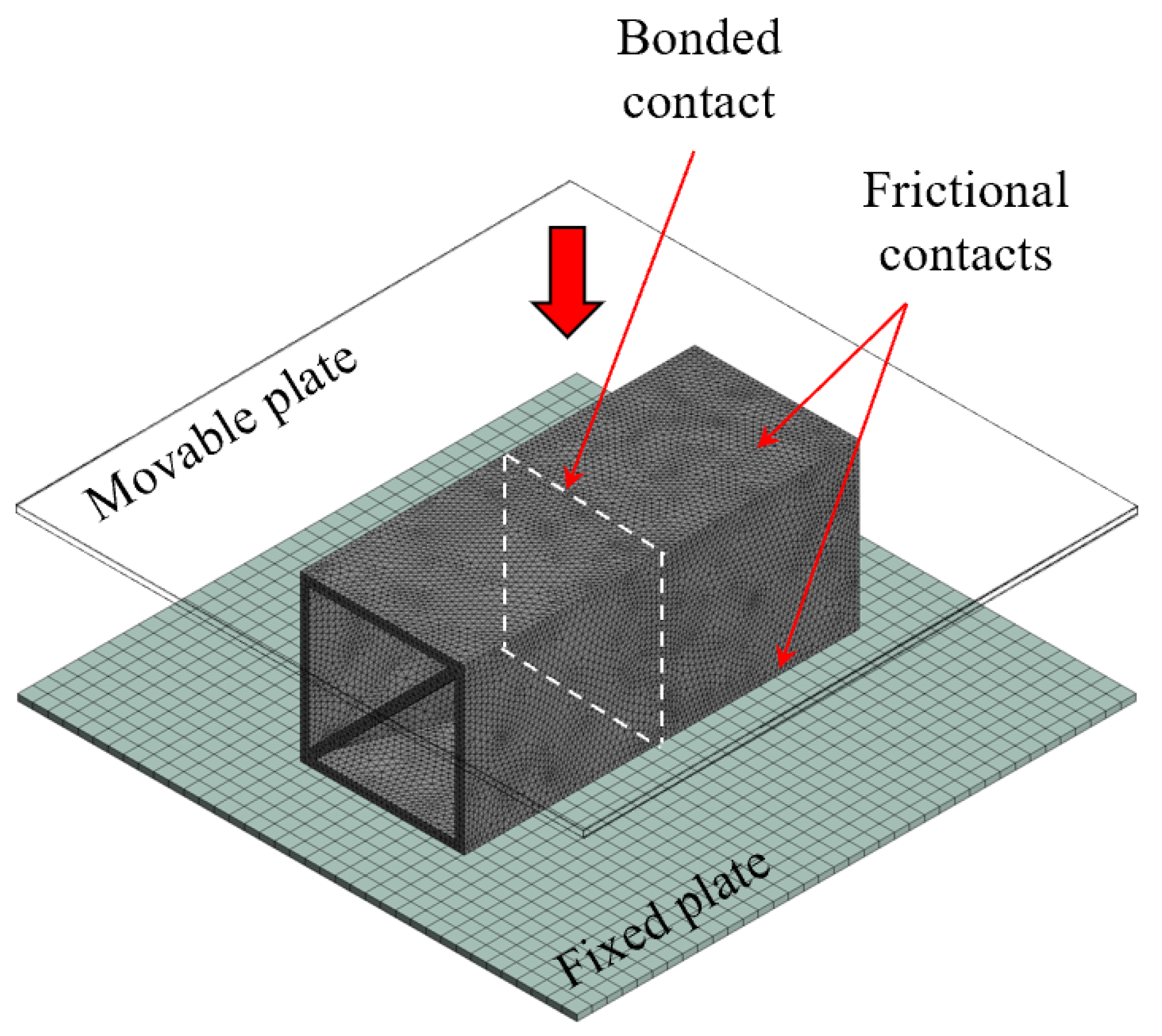
2.4. Numerical Modeling
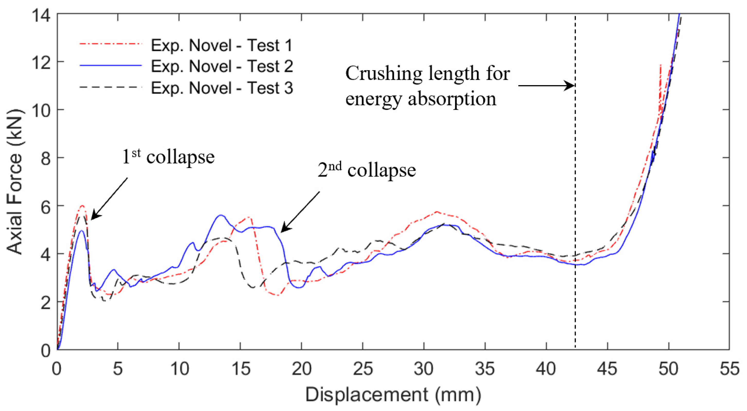
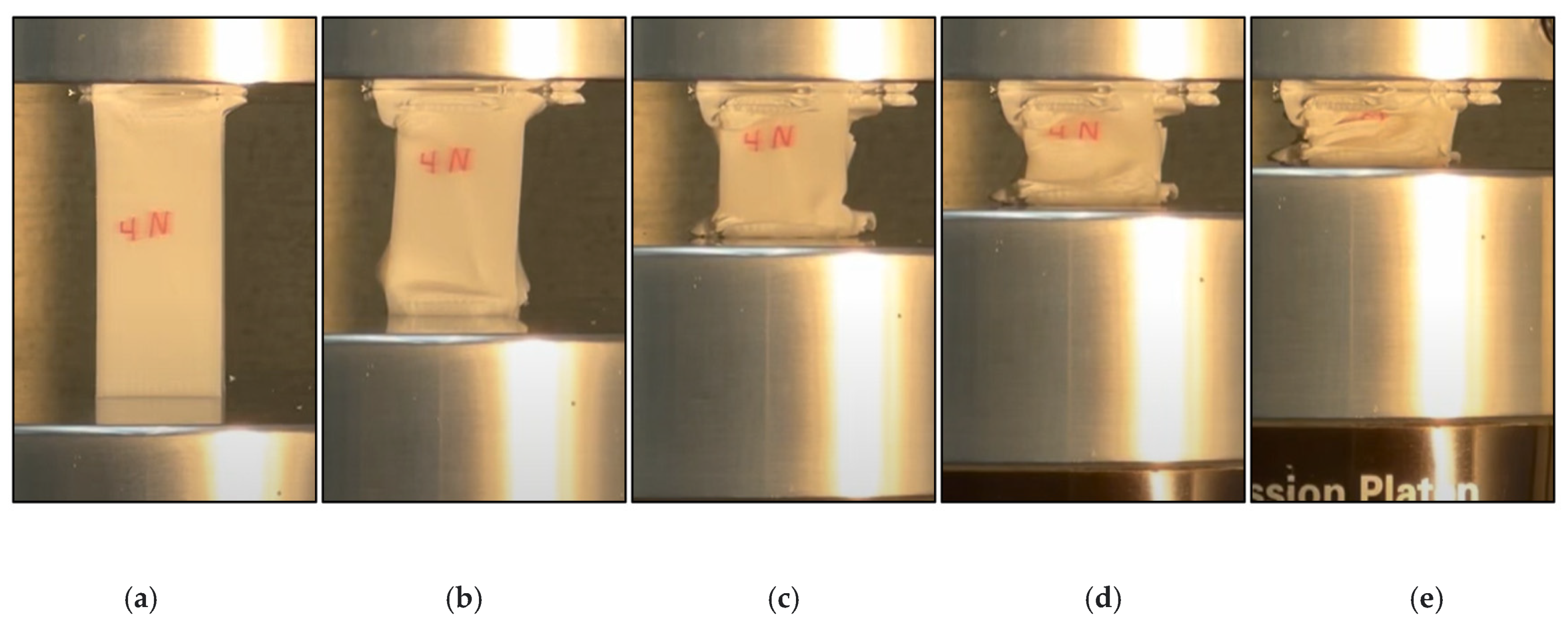
3. Results
4. Discussion
5. Conclusions
6. Patents
Author Contributions
Funding
Institutional Review Board Statement
Informed Consent Statement
Data Availability Statement
Acknowledgments
Conflicts of Interest
References
- Tarlochan, F. Sandwich Structures for Energy Absorption Applications: A Review. Materials 2021, 14, 4731. [Google Scholar] [CrossRef] [PubMed]
- Chen, Y.; Li, T.; Jia, Z.; Scarpa, F.; Yao, C.; Wang, L. 3D printed hierarchical honeycombs with shape integrity under large compressive deformations. Mater. Des. 2018, 137, 226–234. [Google Scholar] [CrossRef] [Green Version]
- Mc Caw, J.C.S.; Cuan-Urquizo, E. Mechanical characterization of 3D printed, non-planar lattice structures under quasi-static cyclic loading. Rapid Prototyp. J. 2020, 26, 707–717. [Google Scholar] [CrossRef]
- Li, T.; Chen, Y.; Hu, X.; Li, Y.; Wang, L. Exploiting negative Poisson’s ratio to design 3D-printed composites with enhanced mechanical properties. Mater. Des. 2018, 142, 247–258. [Google Scholar] [CrossRef]
- Townsend, S.; Adams, R.; Robinson, M.; Hanna, B.; Theobald, P. 3D printed origami honeycombs with tailored out-of-plane energy absorption behavior. Mater. Des. 2020, 195, 108930. [Google Scholar] [CrossRef]
- Bates, S.R.G.; Farrow, I.R.; Trask, R.S. Compressive behaviour of 3D printed thermoplastic polyurethane honeycombs with graded densities. Mater. Des. 2019, 162, 130–142. [Google Scholar] [CrossRef]
- Andrew, J.J.; Alhashmi, H.; Schiffer, A.; Kumar, S.; Deshpande, V.S. Energy absorption and self-sensing performance of 3D printed CF/PEEK cellular composites. Mater. Des. 2021, 208, 109863. [Google Scholar] [CrossRef]
- Ma, J.; Dai, H.; Chai, S.; Chen, Y. Energy absorption of sandwich structures with a kirigami-inspired pyramid foldcore under quasi-static compression and shear. Mater. Des. 2021, 206, 109808. [Google Scholar] [CrossRef]
- Wang, Q.; Yang, Z.; Lu, Z.; Li, X. Mechanical responses of 3D cross-chiral auxetic materials under uniaxial compression. Mater. Des. 2020, 186, 108226. [Google Scholar] [CrossRef]
- Yang, K.; Xu, S.; Shen, J.; Zhou, S.; Xie, Y.M. Energy absorption of thin-walled tubes with pre-folded origami patterns: Numerical simulation and experimental verification. Thin-Walled Struct. 2016, 103, 33–44. [Google Scholar] [CrossRef]
- Li, S.; Liu, Z.; Shim, V.P.W.; Guo, Y.; Sun, Z.; Li, X.; Wang, Z. In-plane compression of 3D-printed self-similar hierarchical honeycombs—Static and dynamic analysis. Thin-Walled Struct. 2020, 157, 106990. [Google Scholar] [CrossRef]
- Qi, J.; Li, C.; Tie, Y.; Zheng, Y.; Duan, Y. Energy absorption characteristics of origami-inspired honeycomb sandwich structures under low-velocity impact loading. Mater. Des. 2021, 207, 109837. [Google Scholar] [CrossRef]
- Guo, C.; Zhao, D.; Liu, Z.; Ding, Q.; Gao, H.; Yan, Q.; Sun, Y.; Ren, F. The 3D-Printed Honeycomb Metamaterials Tubes with Tunable Negative Poisson’s Ratio for High-Performance Static and Dynamic Mechanical Properties. Materials 2021, 14, 1353. [Google Scholar] [CrossRef] [PubMed]
- Zaharia, S.M.; Enescu, L.A.; Pop, M.A. Mechanical Performances of Lightweight Sandwich Structures Produced by Material Extrusion-Based Additive Manufacturing. Polymers 2020, 12, 1740. [Google Scholar] [CrossRef] [PubMed]
- Basurto-Vázquez, O.; Sánchez-Rodríguez, E.P.; McShane, G.J.; Medina, D.I. Load Distribution on PET-G 3D Prints of Honeycomb Cellular Structures under Compression Load. Polymers 2021, 13, 1983. [Google Scholar] [CrossRef] [PubMed]
- Mansour, M.T.; Tsongas, K.; Tzetzis, D. 3D Printed Hierarchical Honeycombs with Carbon Fiber and Carbon Nanotube Reinforced Acrylonitrile Butadiene Styrene. J. Compos. Sci. 2021, 5, 62. [Google Scholar] [CrossRef]
- Sarvestani, H.Y.; Akbarzadeh, A.H.; Mirbolghasemi, A.; Hermenean, K. 3D printed meta-sandwich structures: Failure mechanism, energy absorption and multi-hit capability. Mater. Des. 2018, 160, 179–193. [Google Scholar] [CrossRef]
- Sarvestani, H.Y.; Akbarzadeh, A.H.; Mirbolghasemi, A.; Hermenean, K. 3D printed architected polymeric sandwich panels: Energy absorption and structural performance. Compos. Struct. 2018, 200, 886–909. [Google Scholar] [CrossRef]
- Özen, İ.; Çava, K.; Gedikli, H.; Alver, Ü.; Aslan, M. Low-energy impact response of composite sandwich panels with thermoplastic honeycomb and reentrant cores. Thin-Walled Struct. 2020, 156, 106989. [Google Scholar] [CrossRef]
- Chen, J.; Tao, W.; Pang, S. Impact Testing of 3D Re-Entrant Honeycomb Polyamide Structure Using Split Hopkinson Pressure Bar. Appl. Sci. 2021, 11, 9882. [Google Scholar] [CrossRef]
- Ma, N.; Deng, Q.; Li, X. Deformation Behaviors and Energy Absorption of Composite Re-Entrant Honeycomb Cylindrical Shells under Axial Load. Materials 2021, 14, 7129. [Google Scholar] [CrossRef] [PubMed]
- Gibson, L.J.; Ashby, M.F. Cellular Solids, Structure and Properties, 2nd ed.; Cambridge University Press: Cambridge, UK, 1999; pp. 99–100. [Google Scholar] [CrossRef]


| Parameter | Setting | Parameter | Setting |
|---|---|---|---|
| Analysis type | Explicit-dynamic/quasi-static | Contact type | Frictional |
| Material model | Multilinear isotropic hardening | Static friction coeff. | 0.05 |
| Elastic modulus | 1.2 GPa | Dynamic friction coeff. | 0.05 |
| Yield strength | 20.5 MPa | Hourglass control | Flanagan-Belytschko |
| Poisson’s ratio | 0.3 | Stiffness coeff. | 0.08 |
| Density | 1040 kg/m3 | Viscous coeff. | 0.1 |
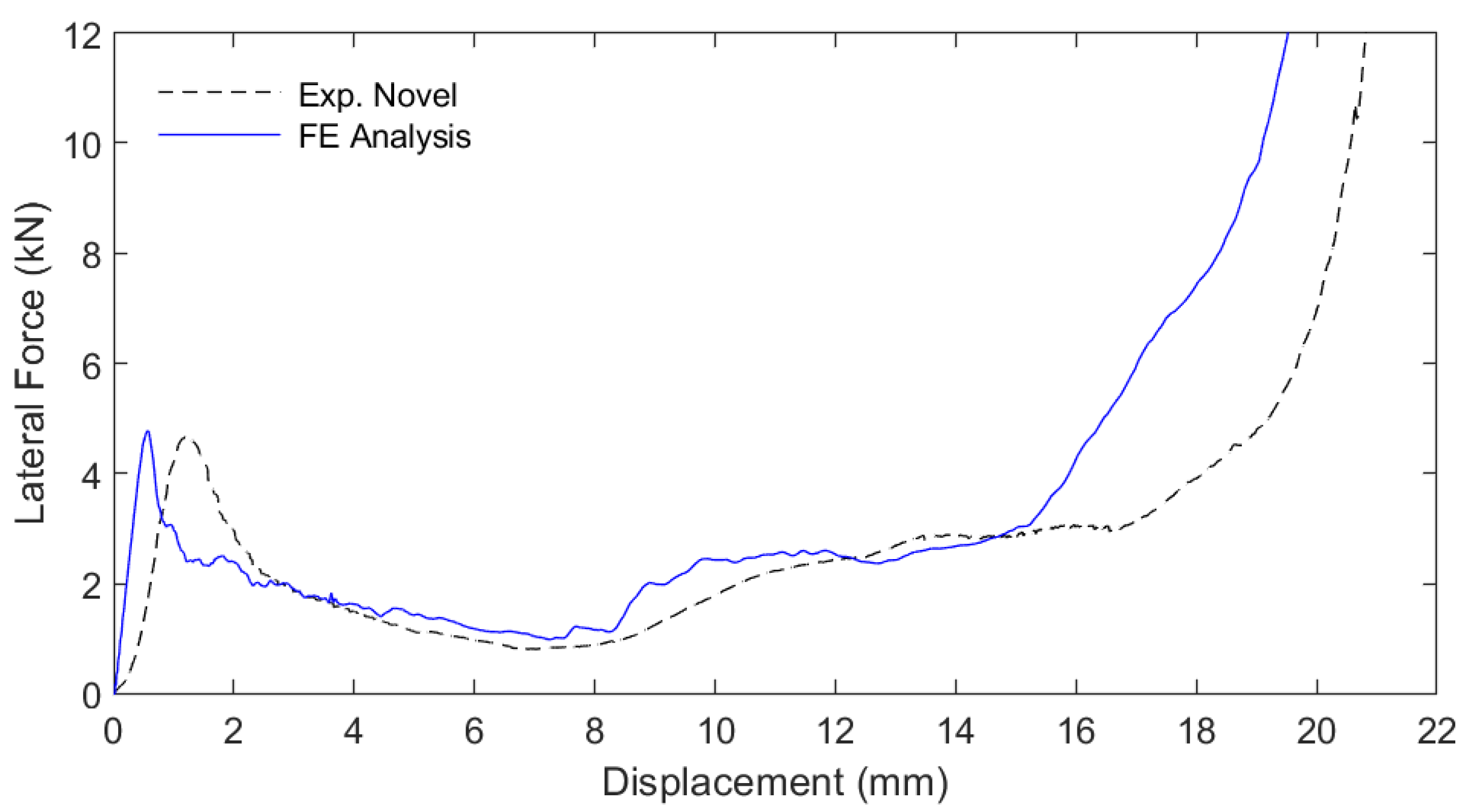
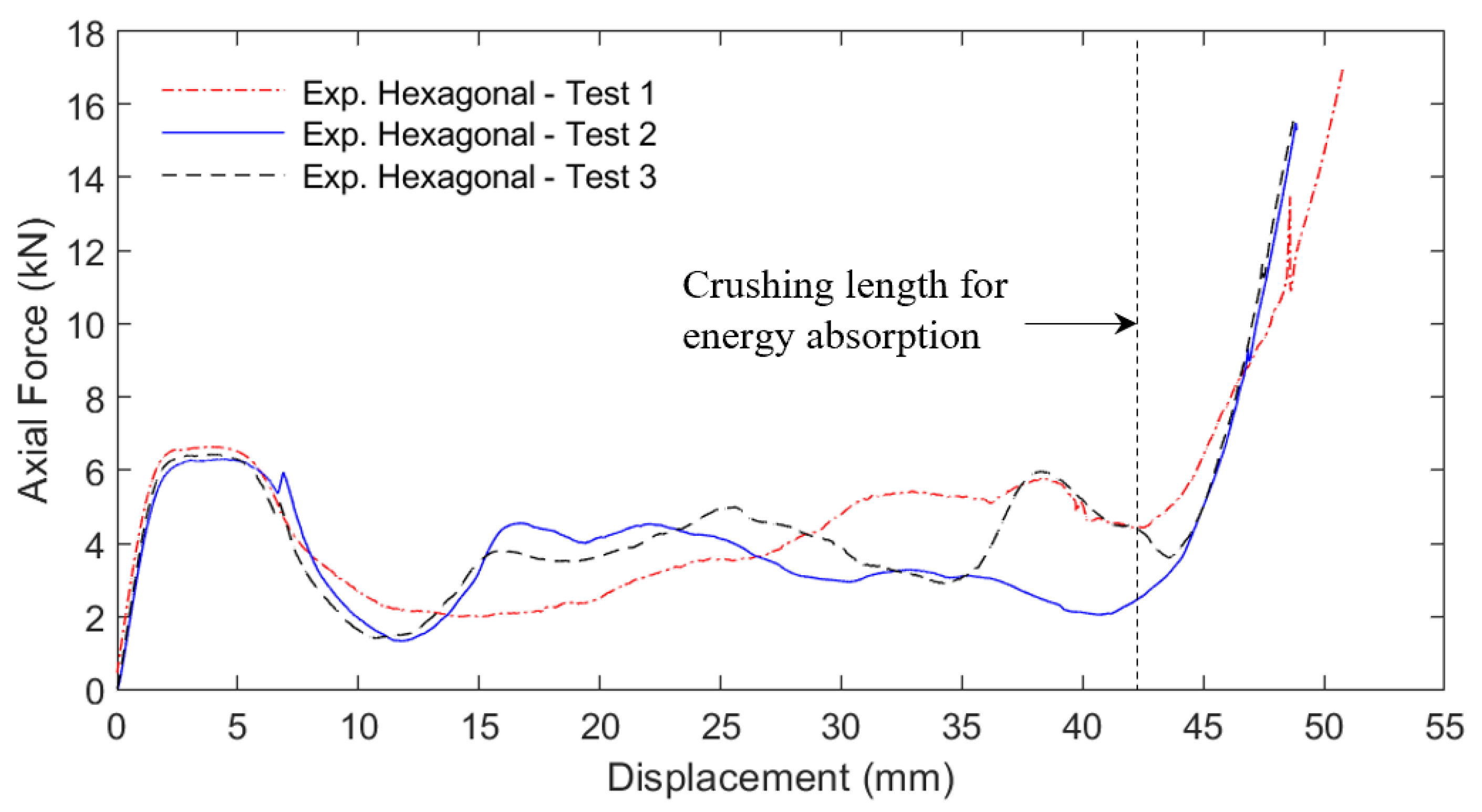
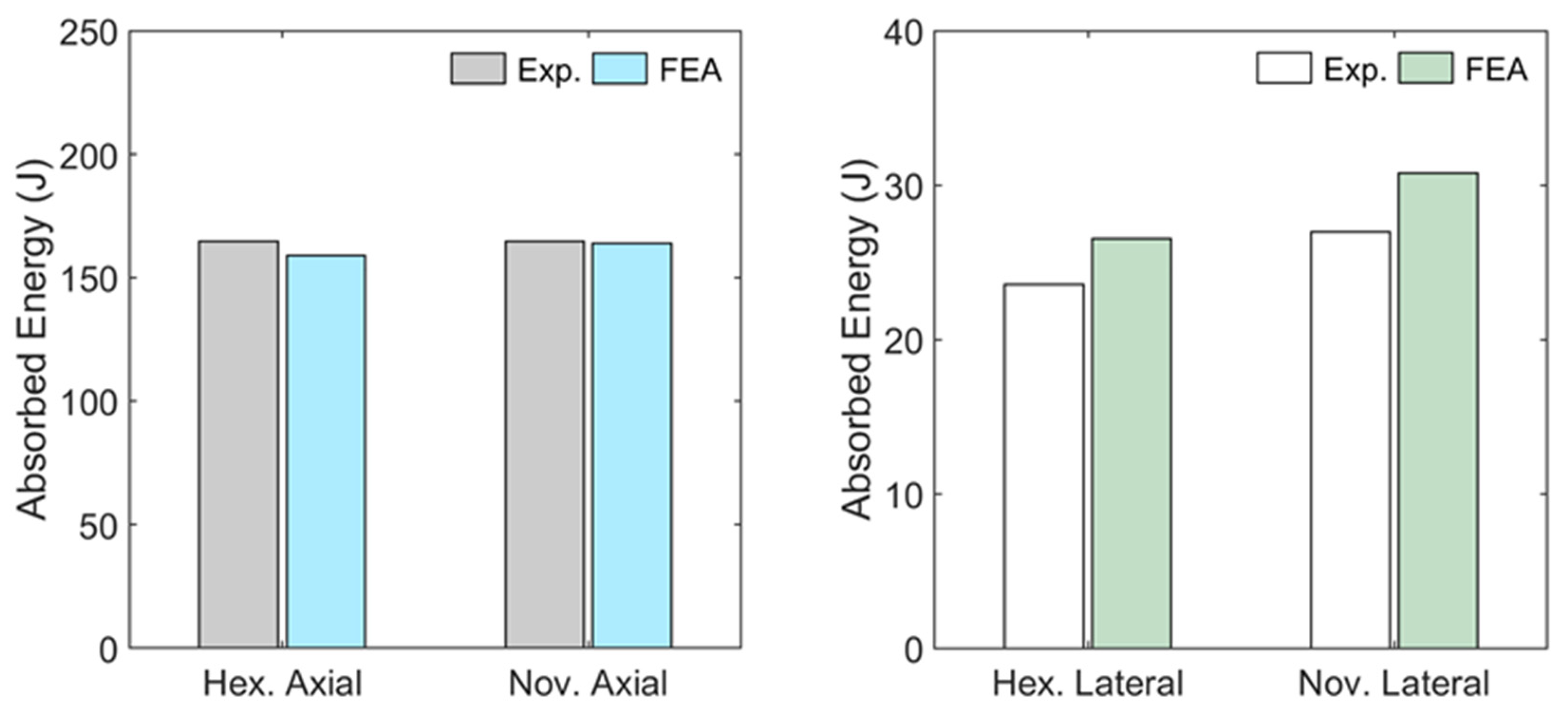
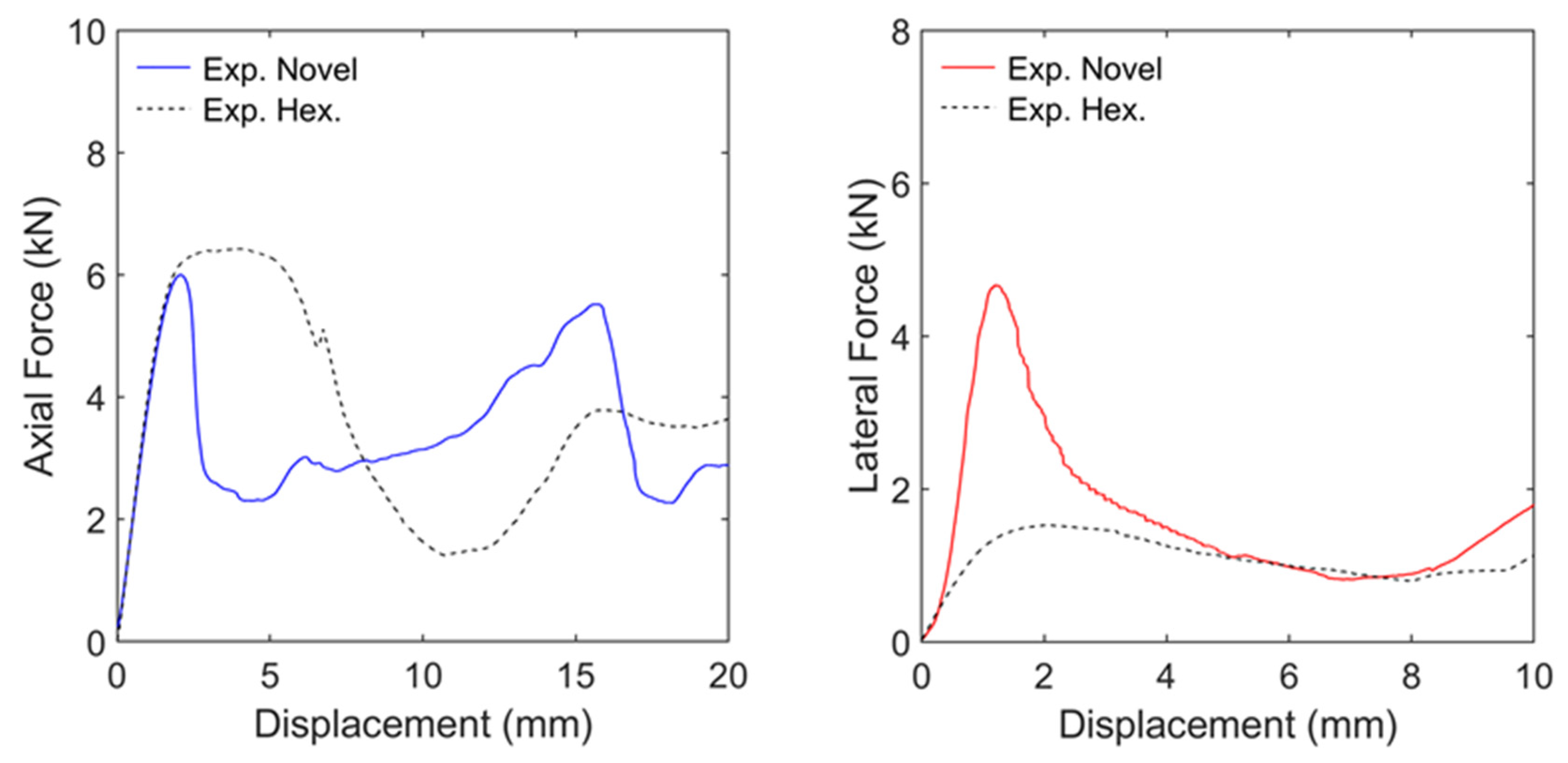
| Cell Geometry (Load Case) | Novel (Axial Load) | Hexagonal (Axial Load) | Novel (Lateral Load) | Hexagonal (Lateral Load) |
|---|---|---|---|---|
| Energy absorption (J) | 164.7 (159.0) | 164.7 (163.9) | 27.0 (30.7) | 23.5 (26.5) |
| Maximum force (kN) | 6.0 (5.6) | 6.5 (6.5) | 4.8 (4.7) | 2.0 (2.4) |
| Specific energy absorption (J/g) | 1.17 | 1.17 | 0.19 | 0.16 |
| Densification length (mm) | 45.0 | 42.5 | 18.0 | 18.0 |
| Crushing length for energy absorption (mm) | 42.3 | 42.3 | 14.8 | 17.5 |
Publisher’s Note: MDPI stays neutral with regard to jurisdictional claims in published maps and institutional affiliations. |
© 2022 by the authors. Licensee MDPI, Basel, Switzerland. This article is an open access article distributed under the terms and conditions of the Creative Commons Attribution (CC BY) license (https://creativecommons.org/licenses/by/4.0/).
Share and Cite
Menegozzo, M.; Cecchini, A.; Just-Agosto, F.A.; Serrano Acevedo, D.; Flores Velez, O.J.; Acevedo-Figueroa, I.; De Jesús Ruiz, J. A 3D-Printed Honeycomb Cell Geometry Design with Enhanced Energy Absorption under Axial and Lateral Quasi-Static Compression Loads. Appl. Mech. 2022, 3, 296-312. https://doi.org/10.3390/applmech3010019
Menegozzo M, Cecchini A, Just-Agosto FA, Serrano Acevedo D, Flores Velez OJ, Acevedo-Figueroa I, De Jesús Ruiz J. A 3D-Printed Honeycomb Cell Geometry Design with Enhanced Energy Absorption under Axial and Lateral Quasi-Static Compression Loads. Applied Mechanics. 2022; 3(1):296-312. https://doi.org/10.3390/applmech3010019
Chicago/Turabian StyleMenegozzo, Marco, Andrés Cecchini, Frederick A. Just-Agosto, David Serrano Acevedo, Orlando J. Flores Velez, Isaac Acevedo-Figueroa, and Jancary De Jesús Ruiz. 2022. "A 3D-Printed Honeycomb Cell Geometry Design with Enhanced Energy Absorption under Axial and Lateral Quasi-Static Compression Loads" Applied Mechanics 3, no. 1: 296-312. https://doi.org/10.3390/applmech3010019
APA StyleMenegozzo, M., Cecchini, A., Just-Agosto, F. A., Serrano Acevedo, D., Flores Velez, O. J., Acevedo-Figueroa, I., & De Jesús Ruiz, J. (2022). A 3D-Printed Honeycomb Cell Geometry Design with Enhanced Energy Absorption under Axial and Lateral Quasi-Static Compression Loads. Applied Mechanics, 3(1), 296-312. https://doi.org/10.3390/applmech3010019