Article

Single-Walled Carbon Nanotube-Enhanced Bagasse-Epoxy Hybrid Composites under Varied Low Tensile Strain Rates

1
Department of Mechanical Engineering, Faculty of Engineering and Science, Curtin University, Miri 98000, Sarawak, Malaysia
2
School of Civil and Mechanical Engineering, Curtin University, Bentley, WA 6102, Australia
3
Adelaide Microscopy, The University of Adelaide, Adelaide, SA 5000, Australia
*
Author to whom correspondence should be addressed.
Appl. Mech. 2021, 2(4), 863-877; https://doi.org/10.3390/applmech2040050
Submission received: 24 August 2021 / Revised: 24 September 2021 / Accepted: 30 September 2021 / Published: 19 October 2021
(This article belongs to the Special Issue Mechanical Properties of Epoxy Construction Materials)

Abstract

:
The production demand of high-performance polymer composites utilizing natural and renewable resources, especially agricultural waste fibres, is rapidly growing. However, these polymers’ mechanical properties are strain rate-dependent due to their viscoelastic nature. Particularly, for natural fibre-reinforced polymer composites (NFPCs), the involvement of fillers has caused rather complex failure mechanisms under different strain rates. Moreover, unevenly and micro-sized bagasse-reinforced polymer composites often cause the formation of micro-cracks and voids in composites. Consequently, the rates of crack initiation and propagation of these composites become extremely sensitive. This, in turn, causes low and unpredictable tensile performance at higher tensile crosshead speeds, even within the low strain rate range. In this study, single-walled carbon nanotubes (SWCNTs) were applied to enhance the bagasse-epoxy composites’ strength. The effects of the weightage in the SWCNT loadings on the composites’ tensile properties were subsequently investigated under low strain rates of 0.0005 s−1, 0.005 s−1 and 0.05 s−1. The composites’ failure shifted to a higher distribution (65.7% improvement, from 37.23 to 61.68 MPa, across strain rates) due to the addition of 0.05% SWCNTs, as indicated in a Weibull distribution plot. The high aspect ratio and strong interface adhesion of SWCNTs in and toward the epoxy matrix contributed significantly to the composites’ strengths. However, a further increase in SWCNT content in the tested composites caused early embrittlement due to agglomeration. The toughness and characteristic strength improved significantly as the strain rate increased. A scanning electron microscopic (SEM) analysis revealed that the SWCNTs’ high aspect ratios and large surface areas improved the interface bonding between the filler and matrix. However, higher SWCNT loadings (0.15% and 0.25%) caused a reverse effect in the same properties of these composites under the same strain rate variations, due to agglomeration. Finally, an empirical relationship was developed to describe the strain rate effect of tensile properties containing 0.05% SWCNT-reinforced bagasse-epoxy composites.

1. Introduction

In the current era, environmental issues have greatly influenced the innovation of polymer composites. The production demand of high-performance polymer composites utilizing natural and renewable resources, especially agricultural waste fibres, is rapidly growing. However, these polymers’ mechanical properties are strain rate-dependent, due to their viscoelastic nature. Particularly, for natural fibre-reinforced polymer composites (NFPCs), the involvement of fillers causes rather complex failure mechanisms under different strain rates. For instance, a study was conducted on hemp-HDPE (high-density polyethylene) composites found that the Young’s modulus and tensile strength increased with increases in strain rate, due to a strain hardening effect [1]. Flax fibre-reinforced epoxy also showed a significant increase in tensile strength under high strain rate loading but little variation at low strain rates [2]. According to another study, different types of natural fibres used in reinforcement, such as fibres from banana, bamboo, or flax, may exhibit different tensile behaviours as the strain rate increases [3].
Recently, studies have been conducted on micro-sized agricultural waste fibre-reinforced polymer composites under low tensile strain rate variations. For instance, adding micron-sized wood particles toward polymer could provide a noticeable improvement under varied low tensile strain rates [4]. Furthermore, experimental results from Kumar et al. [5] showed that crack pinning and crack front twisting appeared as the foremost fracture mechanisms of a coir particle polymer composite under low tensile strain rates. Another study by Kumar and Bhowmik [6] found that changing the tensile speed from 1 mm/min to 2 mm/min could increase the tensile strength of a coir-epoxy composite but would decrease it at 3 mm/min. Bamboo-polyester composites’ tensile properties also fluctuate under low strain rates [7]. According to Kumar et al. [5] this phenomenon is due to uneven micron-sized, or the whisker-formation of, natural fibres causing the formation of microcracks and matrix voids that act as localised stress generators. Hence, these composites become highly crack-sensitive and exhibit unpredictable fracture behaviours under varying tensile strain rates.
Moreover, another study on bagasse-epoxy composites showed that the composites’ tensile strength under low strain rates could be further enhanced by using smaller-sized bagasse fillers [8]. This is attributed to the larger surface area of smaller particles that provide better filler-matrix interface bonding. Literature also proved that by using a micro-mechanical model, fillers at the nanoscale, such as nanoparticles, could potentially further enhance a composite’s strength [9]. Furthermore, Chen et al. [10] found that carbon nanotubes, especially single-walled carbon nanotubes (SWCNT) at higher aspect ratios, are able to provide outstanding interface bonding strength with a polymer matrix, compared with other nanoparticles. However, the effects of the hybridisation of SWCNTs with NFPCs under different low tensile strain rates still remain vague. Hence, bagasse, as one of the agricultural waste fibres used in composite design, was selected in this research to investigate the tensile performance of SWCNTs/bagasse-based epoxy hybrid composites under varied and low strain rates. The Weibull distribution statistical method was employed to characterise the strength distributions of the composites.

2. Experiments

2.1. Materials

An E-132/H-9 two-component, non-volatile and low-viscosity epoxy resin, produced by Fong Yong Chemical Co. Ltd. in Taiwan, was used for our composites’ matrices. The utilised epoxy resin (E-132) had a viscosity of 3–6 Pa · s , and the utilised hardener (H-9) had a viscosity of 0.05–0.1 Pa · s and a mixing pot life of 30 min. The overall epoxy resin density was approximately 1.05–1.14 g/cm3 at room temperature. Sugarcane bagasse fibres were obtained directly from a sugar cane mill in Sarawak, Malaysia. Sodium hydroxide (NaOH) from Fisher Scientific was used as an alkali treatment to remove impurities such as lignin and wax from the bagasse surface. Single-walled carbon nanotubes (with diameters of 1.2–2 nm and lengths of >5 µm) produced by Sigma-Aldrich in the United States, were used as nano-fillers in the composites.

2.2. Sample Preparation

A study by Anggono et al. [11] showed that a higher concentration of NaOH can enhance different bagasse composites’ properties, especially by removing impurities and improving the bagasse’s surface adhesion with polymers. Hence, bagasse was first treated using 5% NaOH solution for 2 h at room temperature, the same as practiced used in literature [11,12] Then, the bagasse was cleaned using distilled water and dried using a BINDER ED 56 convection drying chamber at 90 °C for 24 h. The dried bagasse was ground via disk milling and sieved using an ASTM Standard Stainless Steel Test Sieve with a mesh size of 300 µm, creating a powder form with a particle size of less than 300 µm.
Composites were fabricated by the hand lay-up method using ASTM D638 standard tensile moulds with a 3.2 mm ± 0.4 mm thickness. The fabrication was started by mixing the SWCNTs (for SWCNT composites) with hardener first, then bagasse and epoxy resin were mixed in due to the hardener having a lower viscosity, making it easier to disperse the fillers. It was then immersed in 60 °C water for about 3 min to further lower down the viscosity for degassing purposes. The mixture was then carefully stirred under low viscosity for better dispersion. It was then poured into the waxed tensile mould and left to cure for 24 h under room temperature at 25 °C. After that, the cured composite went through post-curing for 2 h in a drying chamber at 90 °C. This method was suggested by Campana et al. [13] in order to strengthen the crosslinking of the epoxy. Finally, the cured composite was demoulded and left for cooling.

2.3. Materials Characterisation

The composites with 0%, 2%, 4%, 6% and 8% weightages of bagasse were tensile tested using a Lloyd LR10K (West Sussex, UK) universal tester under strain rates of 0.0005 s−1 (0.059 mm/s divided by 118 mm specimen gauge length). The best bagasse loading composite was then chosen for further tensile tests under higher strain rates of 0.005 s−1 and 0.05 s−1. According to literature, these chosen strain rates still fall under a low strain rate range [14]. The selected intervals were also wide enough to observe a more complete low strain rate response. Further reinforcement of the bagasse-epoxy using 0.05%, 0.15% and 0.25% weightages of SWCNTs were also tested under strain rates of 0.0005 s−1, 0.005 s−1 and 0.05 s−1 for comparison. A total of 0.25% of SWCNTs were found to be the maximum achievable weight percentage by the hand lay-up method. The experiment variables are summarised in Table 1.

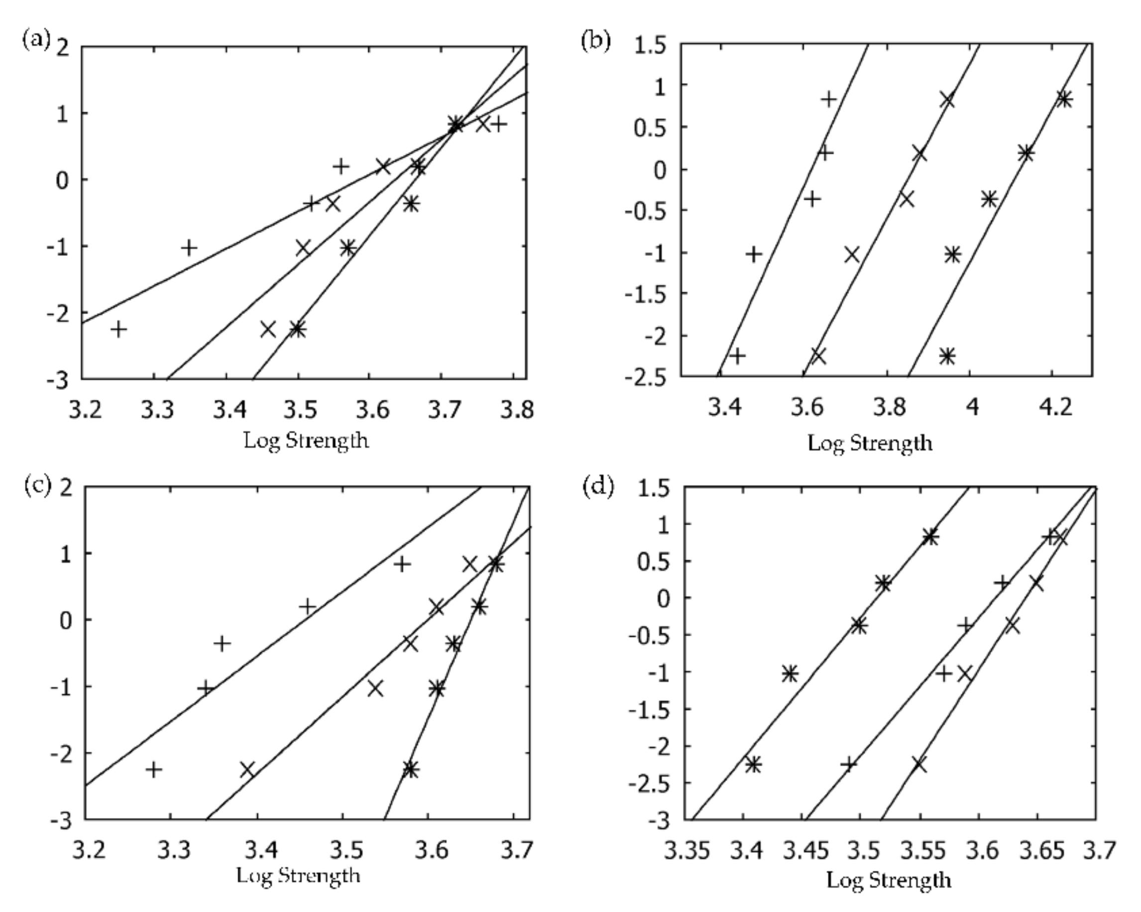
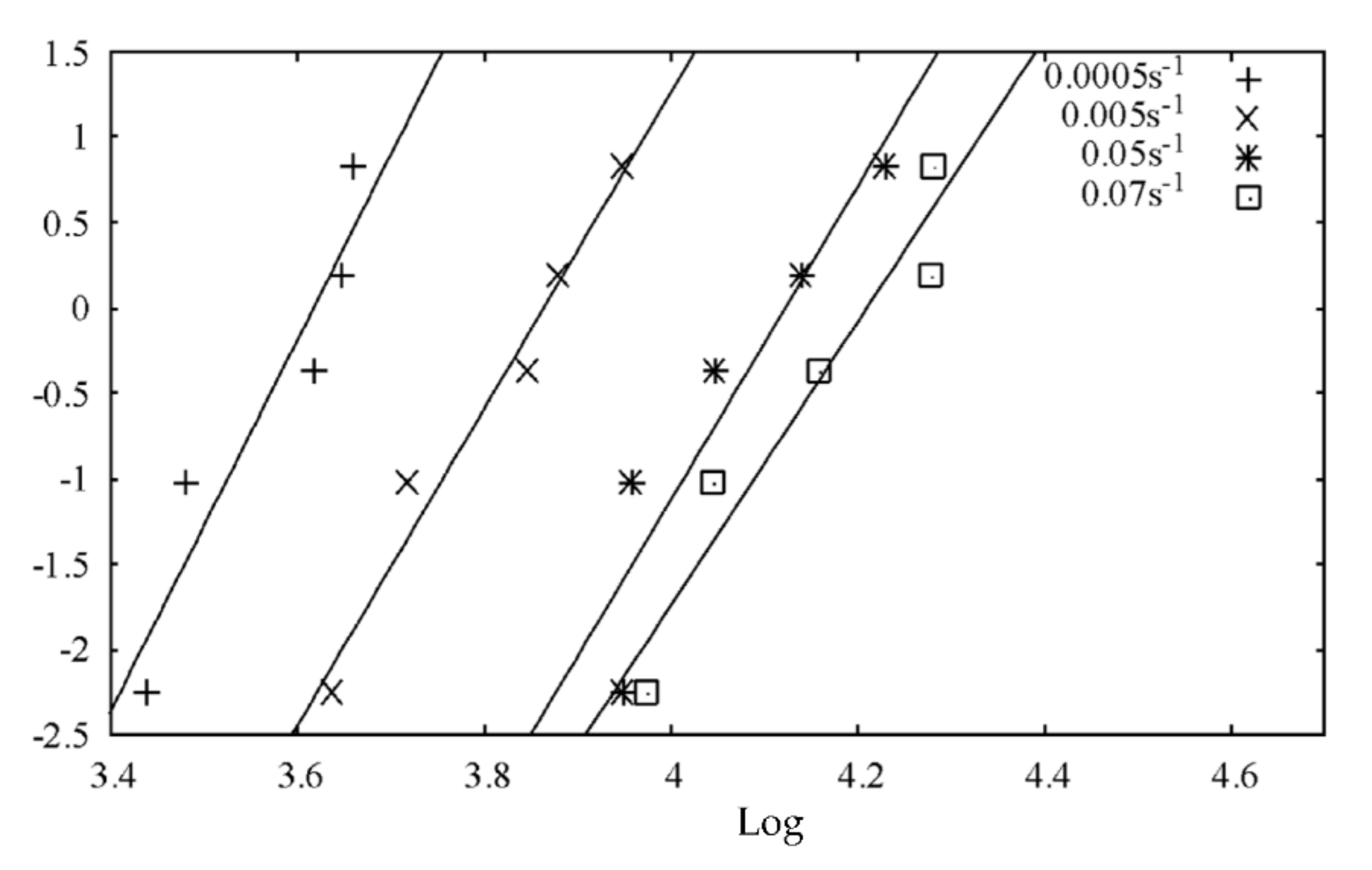
3. Weibull Distribution Method

Sullivan and Lauzon [15] stated the Weibull distribution is a well-known statistical method that uses a probability function to describe the strength distribution of a brittle material, where the strength failure usually occurs at the critical flaw, following the weakest link theory. Lai et al. [16] described the cumulative probability of the failure function P σ of samples at or below a certain level of stress, σ , as:
P σ = 1 e σ σ o m
where m represents the Weibull modulus shape parameter and σ o represents the scale parameter. They are used to describe the strength distribution and characteristic strength (indicating the mean of strength from the distribution) of the material, respectively.
Before conducting the analysis, the material strength data needed to be converted into probability distribution by sorting them ascendingly (from lowest strength to highest). A common probability estimator, Pi, is used to give the probability failure rate for each ranked data, i. Equation (2) shows a probability estimator Pi, where n is the number of the data obtained, and i is the rank of the data. This probability estimator gives the least biased strength data among the other estimators over a small number of samples [17]. Thus, it is preferred for this analysis.
P i = i 0.5 / n
By taking a natural logarithm on both sides of Equation (1) twice, the function is then linearised into a straight line with a certain coefficient of determination R2 (the variability of data points to the regression line):
l n l n 1 1 p i   = m   l n   σ m   l n   σ o  
The gradient of the regression line represents the Weibull modulus (m), whereas the plot-intersection point is used to determine scale parameters, σ o [17].
The scale parameter or characteristic strength can also be obtained using the line equation below:
m   l n   σ o = y   I n t e r c e p t
σ o = e y   I n t e r c e p t m

4. Results and Discussion

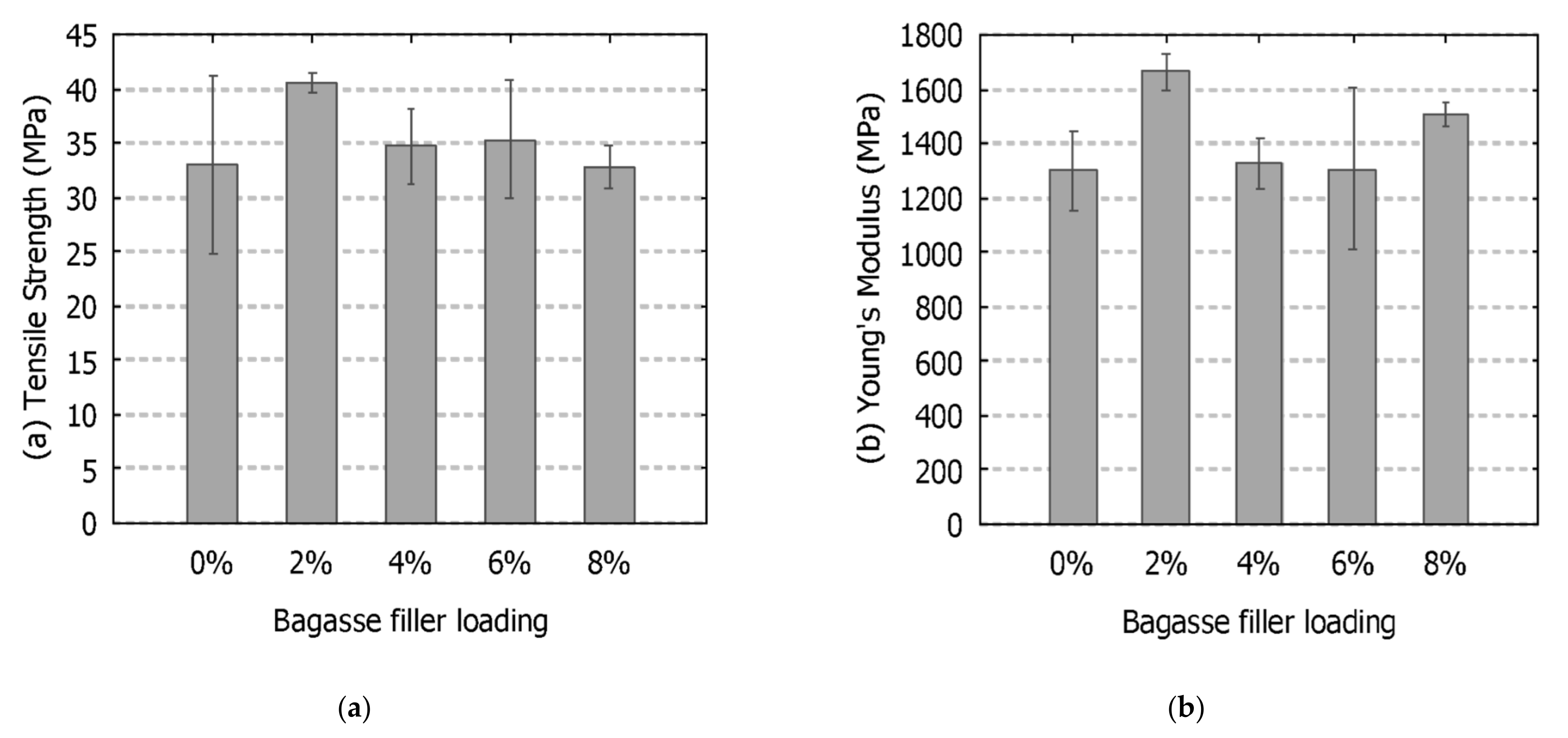
4.1. Bagasse Filler Loadings

The purpose of reinforcement using bagasse filler is to increase the tensile properties of the polymer. Figure 1 shows the tensile strength and Young’s modulus of the bagasse-epoxy composite with different bagasse weightage loadings. It served as a preliminary analysis to find the best bagasse loadings for further SWCNT reinforcement and strain rate tests. The results show that micron-sized bagasse reinforcement increased the tensile strength and stiffness of the composite. The composite with a 2% weightage loading exhibited the highest tensile strength (40.52 MPa) and Young’s modulus (1664.26 MPa). A similar result was reported by Nabinejad et al. [18], where all the tensile strength standard deviations for various polymer types decreased after reinforcement. However, these properties decreased at higher bagasse filler loadings, indicating that filler agglomeration occurred. A study also supported that the large, aggregated bagasse filler could debond early at small stress levels due to a weak filler-matrix interface bonding [19]. The results also show a high standard deviation in neat epoxy which was attributed to some internal defects and voids. A total of 2% bagasse reinforcement was the lowest standard deviation due to the uniform distribution of the bagasse, which improved the composites’ failure consistency.
The micrographs of the scanning electron microscope (SEM) in Figure 2 show the bagasse filler agglomeration sites on the composites’ fracture surfaces. Figure 2a indicates that the inability of epoxy resin to reach the inner part of the agglomeration caused the bagasse filler to be pulled out easily during the deformation. Figure 2b indicates a massive bagasse filler agglomeration which could act as a stress concentration point and result in the deterioration of the composites’ tensile properties. Previous studies on natural fibre-reinforced polymer composites also reported similar results. For instance, Arrakhiz et al. [20] studied on alfa coir- and bagasse-reinforced composites. All of the composites showed lower tensile and flexural properties at a high fibre content due to the agglomerations. Naguib et al. [21] also found the flexural strength and Young’s modulus decreased as the bagasse fibre content increased. Hence, the uniform distribution of the bagasse in the polymer composites is one of the primary factors responsible for mechanical properties.

4.2. Composites under Different Low Strain Rates

Figure 3 shows the linearised Weibull probability plot of SWCNT/bagasse composites with strain rates under 0.0005 s−1, 0.005 s−1 and 0.05 s−1, where the y-axis is the probability of failure calculated using l n l n 1 1 p i   and the x-axis is the natural logarithm of the strength. The line gradient represents the Weibull modulus, m, which describes the failure strength dispersion of the composites. The characteristic strength of the composites was attained by solving Equation (5) for each line equation (refer to Table 2 for detailed data). From the plot, most of the material strength data shifted to the right (higher strength distribution) as the strain rate increased. According to literature, this phenomenon indicates the strain hardening effect, where higher strength will be required for further deformation at higher strain rates [22].
Based on Figure 3a, the characteristic strengths of the bagasse-epoxy composites were found to be 36.08 MPa, 37.94 MPa and 38.96 MPa, respectively, for 0.0005 s−1, 0.005 s−1 and 0.05 s−1 strain rates, slightly incremented (about 8%) from the lowest to the highest strain rate. The Weibull modulus also showed an increasing trend indicating the strength distribution became more consistent as the strain rate increased. This consistent result is attributed to the uniform dispersion of NaOH-treated bagasse, supported by a similar study [23]. Furthermore, the characteristic strengths of the 0.05 wt.% SWCNT-reinforced bagasse-epoxy composites from Figure 3b were about 37.23, 47.7 and 61.68 MPa under three similar strain rates, a significant increase (about 65.7%) from the lowest to the highest strain rate. Moreover, the Weibull moduli are about 10.98, 9.46 and 9.28 across the strain rates; a nonsignificant change was observed, indicating that the overall strength of the composites increased significantly across the strain rates with a very similar dispersion. The origin of this improvement is attributed to the well-dispersed SWCNTs which led to a stronger interface adhesion between the SWCNTs and the epoxy matrix.
However, a further inclusion of SWCNTs led to lower tensile performances. Figure 3c shows the Weibull probability plot of the 0.15 wt.% SWCNT-reinforced bagasse-epoxy composites. The characteristic strengths were recorded as 31.63, 36.58 and 38.43 MPa across each strain rate. Only a 21.5% strength increment from the lowest to the highest strain rate occurred, and the overall strengths were lower than the 0.05 wt.% SWCNT reinforcement. Although the Weibull moduli increased (narrow dispersion), which were about 9.98, 11.75 and 28.87 across the strain rates, this increase only indicates consistent low failure strengths. As for the 0.25 wt.% SWCNT-reinforced bagasse-epoxy composites in Figure 3d, the characteristic strengths were recorded as 37.06, 38.14 and 33.65 MPa with high Weibull moduli of 19.47, 25.26 and 18.69 across each strain rate. The strength showed a slight improvement, from 0.0005 s−1 to 0.005 s−1. However, it decreased significantly at 0.05 s−1, indicating the 0.25% SWCNTs caused agglomerations and could only perform well at the lower tensile strain rates (≤0.005 s−1).

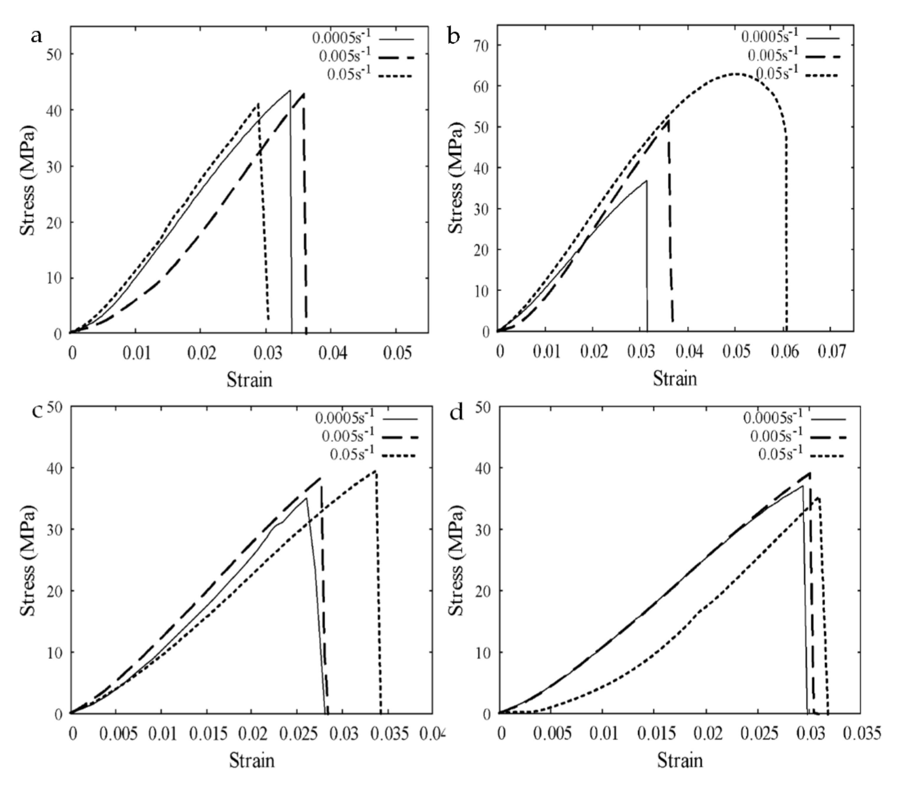
4.3. Stress-Strain Response

The stress-strain response of the composites under different low strain rates was analysed to understand the behaviour of their tensile and fracture toughness. Figure 4 shows the stress-strain responses of the best composite from each strain rate. Fracture toughness values of bagasse-epoxy composites in Figure 4a were around 406.25, 425.39 and 474.19 kJ/m3, respectively, for strain rates of 0.0005 s−1, 0.005 s−1 and 0.05 s−1. The slight improvement in the toughness of bagasse-epoxy indicates that a certain amount of energy was absorbed with the increase in the strain rate. The highest strains at break were about 0.034, 0.036 and 0.03, respectively, for each strain rate. It shows an increase in the strain rate from 0.0005 s−1 to 0.005 s−1 but decrease afterward, with a strain rate of 0.05 s−1. It implies the composites became stiff and brittle at a strain rate of 0.05 s−1 due to strain hardening. Worse results were reported by Kumar and Bhowmik [6], where a significant deterioation in tensile strength was found alongside a speed increase of only 1 mm/min.
Further reinforcement using 0.05 wt.% of SWCNTs increased the toughness of composites to 485.09, 681.41 and 1449.75 kJ/m3 across the strain rates. A significant increase in toughness indicates a large amount of energy absorption of the composites as the strain rate increased. Interestingly, the composites also exhibited an increased amount of deformation in spite of strain hardening, especially at a strain rate of 0.05 s−1, where the maximum strain reached 0.061 (Figure 4b). Some samples at 0.05 s−1 were able to exhibit responses with an ultimate tensile strength before fracture instead of a steep brittle fracture curve. It indicates the high aspect ratio of CNTs or longer CNTs is the key to enhancing the composite’s elasticity, critical strain and tensile strength due to the large interfacial contact region between the fillers and matrix. Similar results were also reported by multiple studies from the literature [24,25]. Additionally, Cui et al. [26] reported that the strain hardening effect of epoxy at higher strain rates caused a stronger interface adhesion between the CNTs and the stiffer matrix, which resulted in an increase in filler breakage with more energy absorbed in the process. Therefore, both the tensile strength and failure strain of the composite improved.
However, the stress-strain response in Figure 4c,d indicate that a further increase in SWCNTs deteriorated the tensile performance, which is in agreement with previous Weibull analysis results. The toughness values obtained from Figure 4c (0.15 wt.% SWCNTs) were about 369.09, 440.87 and 584.32 kJ/m3 across the strain rates (refer to Table 2 for complete test results), indicating less energy absorption when compared to 0.05 wt.% SWCNTs. Whereas in Figure 4d, the toughness values for the 0.25 wt.% SWCNT reinforcement were in a decreasing trend as the strain rate increased, i.e., 493.83, 489.86 and 363.57 kJ/m3 across the strain rates. The composites with higher SWCNT loadings became quite brittle as the strains at break were mostly below 0.03. It could be due to the SWCNT agglomerations which acted as stress concentration points. These points could easily lead to crack initiation and propagation within the composites. The agglomerations that took place are mainly due to the CNTs having fully occupied the space within the epoxy (reaching the volume limit). Similar problems were also reported by literature, where the CNTs stuck together (agglomeration) due to van der Waals forces, leading to the poor performance of the composite as the filler-matrix interface’s stress transfer efficiency decreased [10]. Pratyush et al. [27] also reviewed many studies and noted the poor dispersion effects of CNTs when the amount was beyond the limit where agglomeration begins to deteriorate the mechanical properties. Furthermore, Shen et al. [28] were only able to achieve a maximum of 0.6 wt.% of CNTs using the heat pressure mould fabrication method. Thus, higher CNT inclusion in the composite is still a challenging task.

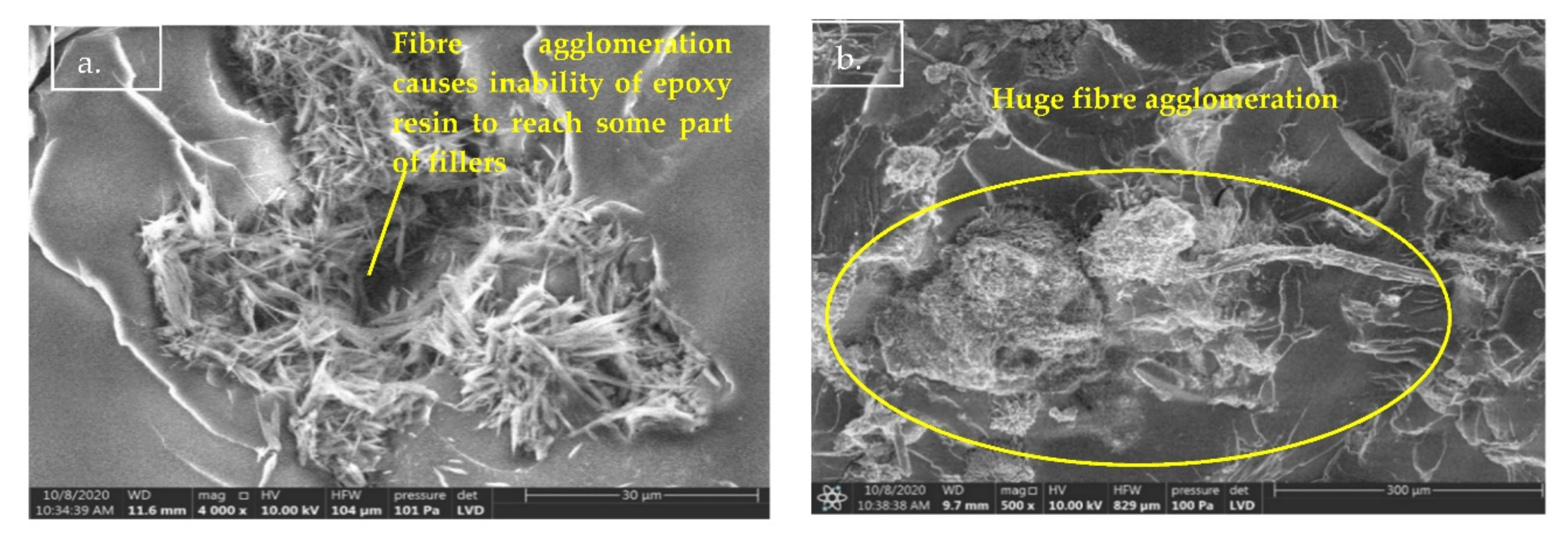
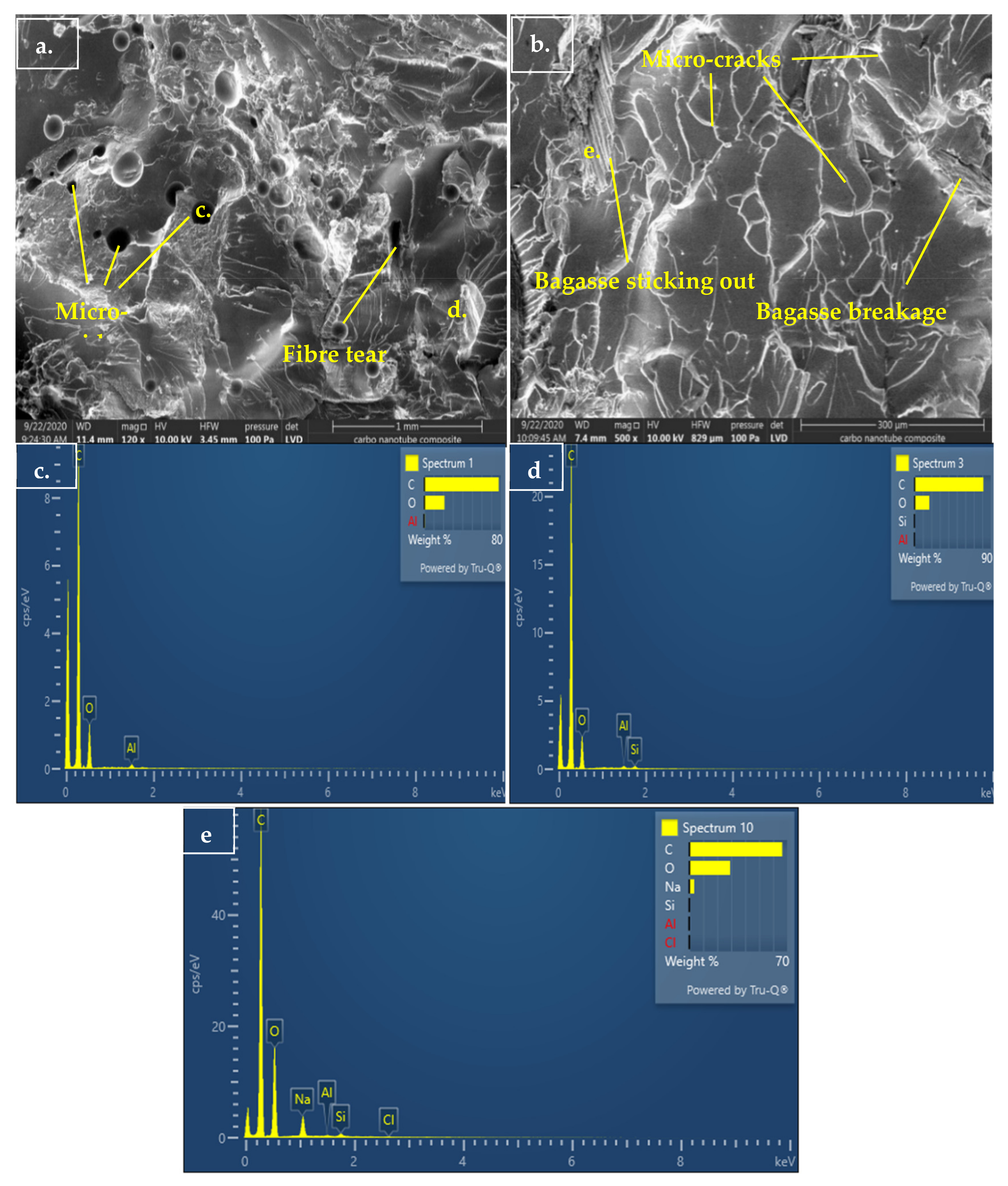
4.4. Fracture Surface Morphology under Different Strain Rates

Figure 5 shows the SEM micrograph of the bagasse-epoxy composite fracture surfaces under a strain rate of 0.05 s−1. Although the bagasse fillers were finely dispersed (Figure 5a), a fine filler pull-out hole (<100 µm) was noticed in Figure 5b, indicating the adhesion between the bagasse filler and matrix was not strong enough at a strain rate of 0.05 s−1. Multiple micro-cracks, crack deflections and crack bifurcations were among the toughening mechanisms spotted around the bagasse filler in Figure 5a. However, river-like cleavages were also observed, which indicated the transition of ductile to brittle behaviour started at a strain rate of 0.05 s−1.
Figure 6 shows the fracture surface micrograph and energy-dispersive X-ray (EDX) analysis results of the composites after the inclusion of 0.05 wt.% SWCNTs. Figure 6a shows multiple micro-voids and some concave surfaces, indicating that some degree of ductile plastic deformation occurred in the composites after the SWCNT reinforcement. Moreover, filler tearing, filler breakage, crack deflections and bifurcations are the strengthening mechanisms observed on the surface of the SWCNT composites in Figure 6a,b.
Furthermore, the EDX analysis results (Figure 6c–e) indicated that carbon was the main element on the fracture surfaces. In terms of quantitative analysis, the carbon element was about 70–90%, varying depending on the surface’s locations. Figure 6e reveals a high count of the carbon element around a large, protruding fractured bagasse. Possibly, the presence of the carbon element and the CNTs effectively strengthened the adhesion of the filler-matrix interface. It prevented the bagasse from being pulled out entirely. According to a study, by considering the interactions between different fillers in their micromechanical model on crack-bridging relations, the model curves showed a higher tensile strength than the model without filler-filler interactions [29]. Moreover, Shen et al. [28] suggested that CNTs can react with the active groups of epoxy to increase the carbon-carbon covalent bond, thus enhancing the interface bonding.
The relatively smooth fracture surface of the composite in Figure 7a (SEM micrograph of the 0.05 wt.% SWCNT-reinforced bagasse-epoxy under a strain rate of 0.05 s−1) indicates brittle fracture due to the strain hardening effect of the epoxy matrix. Moreover, a fine aggregation of CNTs are visible around the micro-voids in Figure 7b. These CNTs caused a lot of crack bifurcations and deflections around them. Zotti et al. [30] described how these cracks create larger and multiple fracture surfaces, which consume high energy. Thus, it once again indicates a large amount of energy was absorbed by the composite under a strain rate of 0.05 s−1.
Furthermore, some agglomerations were noticed on the fracture surface of the 0.15 wt.% SWCNT reinforcement in Figure 8a. One of the agglomeration sites was enlarged in Figure 8b. It shows the aggregated SWCNTs were partially pulled out at the lowest strain rate. Although some agglomerations happened, the increasing amount of crack pinning can also be observed in the composite that went through higher strain rate testing (Figure 9). According to Zotti et al. [30], the amount of energy needed to cause fracture has a proportional relationship to the r b ratio, where r is the radius of the fillers encountered, and b is the half-distance between fillers that cause crack pinning. Hence, this explains the previous analysis, where the agglomerated 0.15 wt.% SWCNTs (large r value) were still able to slightly increase the tensile properties by pinning multiple cracks within a close distance (small b value).
Figure 10 shows the fracture surface of the 0.25 wt.% SWCNT-reinforced bagasse composite under low (Figure 10a) and high (Figure 10b) magnifications. A massive agglomeration of CNTs was spotted with some parts pulled out. A huge, black dark spot comprised of CNTs shifted near the surface, which looked different from those above the surface. Vladar [31] stated this effect was due to SEM varying the landing energy, the extent of electron beam penetration and the complex internal system of conductive and non-conductive areas around the CNTs. The surface looks relatively smooth with fewer cracking mechanisms, indicating the embrittlement of the composites at a strain rate of 0.05 s−1.

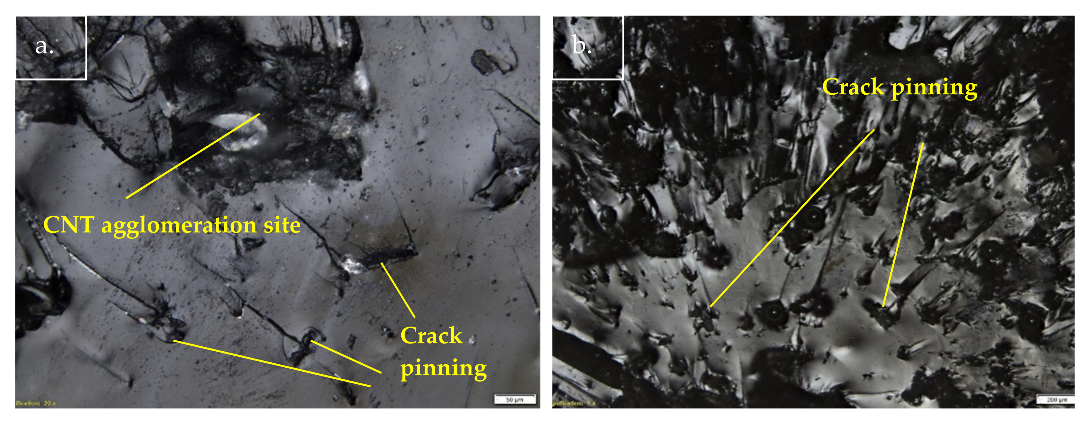
4.5. Low Strain Rate Behaviour of 0.05 wt.% SWCNT-Reinforced Bagasse-Epoxy

The 0.05 wt.% SWCNT-reinforced bagasse-epoxy composite achieved the highest tensile performance at all tested strain rates, indicating strong interface bonding between the filler and matrix. Thus, strong interface bonding is the key to enhance the dynamic tensile performance of the composite. Next, the 0.05 wt.% SWCNTs was further tested under a higher strain rate (0.07 s−1) to validate the hypothesis and establish empirical models. Moreover, the result of 0.07 s−1 is plotted together with previous strain rates for comparison in Figure 11. The characteristic strength Weibull plot for a strain rate of 0.07 s−1 was about 67.41 MPa, which is a further 9.3% strength improvement compared to the composite under a strain rate of 0.05 s−1. However, the Weibull modulus slightly decreased at 0.07 s−1, indicating the strength data was a little more widely dispersed. At higher strain rates, this is reasonable due to polymer strain-hardening and ductile-to-brittle transitions. A study also stated this high strain rate-induced hardening reduced the plastic deformation, delayed the necking instability and resulted in the possibility of the composite randomly failing at any instance [32].
The overall empirical relationship between the tensile properties of 0.05 wt.% SWCNT-reinforced bagasse-epoxy at low strain rates was illustrated in Figure 12. Empirical equations have been proposed to describe the strain rate effect on the primary properties (characteristic strength and toughness) of the 0.05 wt.% SWCNT composites. The characteristic strength of the 0.05 wt.% SWCNT-reinforced bagasse-epoxy had an inverse exponential growth as the strain rate increased. On the other hand, the toughness had a positive exponential growth as the strain rate increased.

5. Conclusions

The uneven, micro-sized natural fibre-reinforced polymer composite was found to underperform at higher tensile testing crosshead speeds even within a low strain rate range. SWCNT reinforcement could further enhance the composite’s strength in this direction. The morphology of the fracture surfaces was analysed to understand the fracture mechanisms of composites under different low strain rates. Thus, with the experimental results and associated discussion, the key findings from the present study are summarised below.
In the preliminary bagasse filler loading tests, the 2 wt.% bagasse loading exhibited the highest tensile performance under the lowest strain rates (0.0005 s−1). However, the composite only showed a slightly improved tensile performance as the strain rate increased.
In agreement with previously established literature, the bagasse-epoxy, as one of the uneven and micro-sized natural fibre-reinforced polymer composites, exhibited weak filler-matrix interface bonding, causing low tensile performance under various low tensile strain rates.
Further reinforcement using 0.05 wt.% of SWCNTs significantly enhanced the tensile performance of 2 wt.% bagasse-epoxy composites under varying low strain rates, which was attributed to their high aspect ratio and strong interface adhesion toward the epoxy matrix.
The 0.05 wt.% of SWCNT-reinforced bagasse-epoxy also showed an increased amount of deformation at higher strain rates, although strain hardening happened. This was attributed to the stiffened matrix, which could cause stronger adhesion to SWCNTs, allowing further deformation. However, further inclusion of the SWCNTs in the composite caused early embrittlement at lower strain rates due to agglomerations.
The 0.05 wt.% SWCNT-reinforcement with a strong filler-matrix interface bonding was validated using a higher strain rate (0.07 s−1), accounting for another 9.3% improvement in the characteristic strength compared to the composite with a strain rate under 0.05 s−1.
Accordingly, empirical models were developed, which showed that the characteristic strength of 0.05 wt.% SWCNT-reinforced bagasse-epoxy had an inverse exponential growth as the strain rate increased. On the other hand, its toughness had a positive exponential growth along with the increase in the strain rate.
Hence, the results have shown that SWCNTs are able to provide further enhancement on some tensile properties of bagasse-epoxy composites under varied low strain rates. This study has shown that SWCNTs have the potential to be utilised in automotive and aerospace industries due to their high strength-to-weight ratio and mechanical competence under different tensile strain rate loading conditions. They could also be utilised in the construction industry such as in the construction of high architectural structures and bridges that could sustain earthquake- or wind-induced dynamic motions.

Author Contributions

Conceptualization, S.D. and T.K.K.; methodology, S.D. and T.K.K.; investigation, S.D. and T.K.K.; formal analysis, S.D., T.K.K. and M.A.; writing–original draft preparation, S.D. and T.K.K.; writing–review and editing, A.P. and A.K.B.; supervision, S.D. All authors have read and agreed to the published version of the manuscript.

Funding

This research received no external funding.

Institutional Review Board Statement

Not applicable.

Informed Consent Statement

Not applicable.

Data Availability Statement

Available on request from the authors.

Conflicts of Interest

The authors declare no conflict of interest.

References

  1. Fotouh, A.; Wolodko, J.D.; Lipsett, M.G. Characterization and modeling of strain rate hardening in natural-fiber-reinforced viscoplastic polymer. Polym. Compos. 2014, 35, 2290–2296. [Google Scholar] [CrossRef]
  2. Wang, W.; Zhang, X.; Chouw, N.; Li, Z.; Shi, Y. Strain rate effect on the dynamic tensile behaviour of flax fibre reinforced polymer. Compos. Struct. 2018, 200, 135–143. [Google Scholar] [CrossRef]
  3. Chokshi, S.; Gohill, P. Effect of Strain Rate on Tensile Strength Of Natural Fiber Reinforced Polyester Composites. Int. J. Mech. Eng. Technol. 2018, 9, 861–869. [Google Scholar]
  4. Kumar, R.; Kumar, K.; Bhowmik, S. Mechanical characterization and quantification of tensile, fracture and viscoelastic characteristics of wood filler reinforced epoxy composite. Wood Sci. Technol. 2018, 52, 677–699. [Google Scholar] [CrossRef]
  5. Kumar, R.; Kumar, K.; Bhowmik, S. Assessment and Response of Treated Cocos nucifera Reinforced Toughened Epoxy Composite Towards Fracture and Viscoelastic Properties. J. Polym. Environ. 2017, 26, 2522–2535. [Google Scholar] [CrossRef]
  6. Kumar, R.; Bhowmik, S. Elucidating the Coir Particle Filler Interaction in Epoxy Polymer Composites at Low Strain Rate. Fibers Polym. 2019, 20, 428–439. [Google Scholar] [CrossRef]
  7. Patel, M.; Chokshi, S. Experimental Investigation on Tensile Strength of Natural Fiber Composites with Varying Strain Rate. Int. J. Electron. Electr. Comput. Syst. 2017, 6, 477–484. [Google Scholar]
  8. Debnath, S.; Khieng, T.K.; Anwar, M.; Basak, A.K.; Pramanik, A. Strain Rate Sensitivity of Epoxy Composites Reinforced with Varied Sizes of Bagasse Particles. J. Compos. Sci. 2020, 4, 110. [Google Scholar] [CrossRef]
  9. Lauke, B. On the effect of particle size on fracture toughness of polymer composites. Compos. Sci. Technol. 2008, 68, 3365–3372. [Google Scholar] [CrossRef] [Green Version]
  10. Chen, J.; Liu, B.; Gao, X.; Xu, D. A review of the interfacial characteristics of polymer nanocomposites containing carbon nanotubes. RSC Adv. 2018, 8, 28048–28085. [Google Scholar] [CrossRef] [Green Version]
  11. Anggono, J.; Habibi, N.R.; Sugondo, D.S. Alkali Treatment on Sugarcane Bagasse to Improve Properties of Green Composites of Sugarcane Bagasse Fibers-Polypropylene. In Ceramic Engineering and Science Proceedings; Wiley: Hoboken, NJ, USA, 2014; pp. 139–149. [Google Scholar]
  12. Acharya, S.K.; Punyapriya, M.; Suraj, K.M. Effect of surface treatment on the mechanical properties of bagasse fiber reinforced polymer composite. BioResources 2011, 6, 3155–3165. [Google Scholar]
  13. Campana, C.; Leger, R.; Sonnier, R.; Ferry, L.; Ienny, P. Effect of post curing temperature on mechanical properties of a flax fiber reinforced epoxy composite. Compos. Part A Appl. Sci. Manuf. 2018, 107, 171–179. [Google Scholar] [CrossRef]
  14. Othman, H.; Marzouk, H. Strain Rate Sensitivity of Fiber-Reinforced Cementitious Composites. ACI Mater. J. 2016, 113, 143–150. [Google Scholar] [CrossRef]
  15. Sullivan, J.D.; Lauzon, P.H. Experimental probability estimators for Weibull plots. J. Mater. Sci. Lett. 1986, 5, 1245–1247. [Google Scholar] [CrossRef]
  16. Lai, C.-D.; Murthy, D.; Xie, M. Weibull Distributions and Their Applications. Springer Handbook of Engineering Statistics; Springer: Amsterdam, The Netherlands, 2006; Chapter 3; pp. 63–78. [Google Scholar] [CrossRef]
  17. Saghafi, A.; Mirhabibi, A.; Yari, G. Improved linear regression method for estimating Weibull parameters. Theor. Appl. Fract. Mech. 2009, 52, 180–182. [Google Scholar] [CrossRef]
  18. Nabinejad, O.; Sujan, D.; Rahman, M.E.; Davies, I. Effect of filler load on the curing behavior and mechanical and thermal performance of wood flour filled thermoset composites. J. Clean. Prod. 2017, 164, 1145–1156. [Google Scholar] [CrossRef]
  19. Anggono, J.; Ágnes, E.F.; Bartos, A.; Móczó, J.; Antoni, R.; Purwaningsih, H.; Pukánszky, B. Deformation and failure of sugarcane bagasse reinforced PP. Eur. Polym. J. 2019, 112, 153–160. [Google Scholar] [CrossRef] [Green Version]
  20. Arrakhiz, F.; Malha, M.; Bouhfid, R.; Benmoussa, K.; Qaiss, A.E.K. Tensile, flexural and torsional properties of chemically treated alfa, coir and bagasse reinforced polypropylene. Compos. Part B Eng. 2013, 47, 35–41. [Google Scholar] [CrossRef]
  21. Naguib, H.M.; Kandil, U.F.; Hashem, A.I.; Boghdadi, Y.M. Effect of fiber loading on the mechanical and physical properties of “green” bagasse–polyester composite. J. Radiat. Res. Appl. Sci. 2015, 8, 544–548. [Google Scholar] [CrossRef] [Green Version]
  22. Siviour, C.R.; Jordan, J.L. High Strain Rate Mechanics of Polymers: A Review. J. Dyn. Behav. Mater. 2016, 2, 15–32. [Google Scholar] [CrossRef] [Green Version]
  23. Jasmi, N.F.; Kasim, J.; Ansar, M.S.; Maidin, I.I. The Role of Oil Palm (Elaeis guineensis) Frond as Filler in Polypropylene Matrix with Relation of Filler Loading and Particle Size Effects. In Regional Conference on Science, Technology and Social Sciences; Springer: Amsterdam, The Netherlands, 2016; pp. 393–403. [Google Scholar] [CrossRef]
  24. Arash, B.; Park, H.S.; Rabczuk, T. Tensile fracture behavior of short carbon nanotube reinforced polymer composites: A coarse-grained model. Compos. Struct. 2015, 134, 981–988. [Google Scholar] [CrossRef] [Green Version]
  25. Li, Y.; Wang, Q.; Wang, S. A review on enhancement of mechanical and tribological properties of polymer composites reinforced by carbon nanotubes and graphene sheet: Molecular dynamics simulations. Compos. Part B Eng. 2019, 160, 348–361. [Google Scholar] [CrossRef]
  26. Cui, J.; Wang, S.; Wang, S.; Li, G.; Wang, P.; Liang, C. The Effects of Strain Rates on Mechanical Properties and Failure Behavior of Long Glass Fiber Reinforced Thermoplastic Composites. Polymers 2019, 11, 2019. [Google Scholar] [CrossRef] [Green Version]
  27. Behera, R.P.; Rawat, P.; Tiwari, S.K.; Singh, K.K. A brief review on the mechanical properties of Carbon nanotube reinforced polymer composites. Mater. Today Proc. 2020, 22, 2109–2117. [Google Scholar] [CrossRef]
  28. Shen, X.; Jia, J.; Chen, C.; Li, Y.; Kim, J.-K. Enhancement of mechanical properties of natural fiber composites via carbon nanotube addition. J. Mater. Sci. 2014, 49, 3225–3233. [Google Scholar] [CrossRef]
  29. Yu, J.; Chen, Y.; Leung, C.K. Micromechanical modeling of crack-bridging relations of hybrid-fiber Strain-Hardening Cementitious Composites considering interaction between different fibers. Constr. Build. Mater. 2018, 182, 629–636. [Google Scholar] [CrossRef]
  30. Zotti, A.; Zuppolini, S.; Zarrelli, M.; Borriello, A. Fracture Toughening Mechanisms in Epoxy Adhesives. In Adhesives—Applications and Properties; Rudawska, A., Ed.; InTech: London, UK, 2016; pp. 239–269. [Google Scholar]
  31. Vládar, A.E. Strategies for Scanning Electron Microscopy Sample Preparation and Characterization of Multiwall Carbon Nanotube Polymer Composites; National Institute of Standards and Technology (NIST): Gaithersburg, MD, USA, 2016.
  32. Yang, X.; Zhang, B. Material embrittlement in high strain-rate loading. Int. J. Extrem. Manuf. 2019, 1, 022003. [Google Scholar] [CrossRef]
Figure 1. Tensile properties of composites with different bagasse weightage content (a) Tensile strength, (b) Young’s modulus.
Applmech 02 00050 g001
Figure 2. SEM micrograph of the fracture surfaces of the composites with high bagasse content; (a) 6 wt.%, (b) 8 wt.%.
Applmech 02 00050 g002
Figure 3. Linearised Weibull probability plot of different weightages of SWCNT-reinforced bagasse-epoxy under varied strain rates. (a) 0 wt.%, (b) 0.05 wt.%, (c) 0.15 wt.%, (d) 0.25 wt.%.
Applmech 02 00050 g003
Figure 4. Stress-strain responses of different weightages of SWCNT-reinforced bagasse-epoxy under varied strain rates (a) 0 wt.%, (b) 0.05 wt.%, (c) 0.15 wt.%, (d) 0.25 wt.%.
Applmech 02 00050 g004
Figure 5. SEM micrograph of 2 wt.% bagasse-epoxy fracture surfaces at a strain rate of 0.05 s−1: (a) finely dispersed filler around the crack and (b) fine filler pull-out holes.
Applmech 02 00050 g005
Figure 6. SEM micrograph of 0.05 wt.% SWCNT-reinforced bagasse-epoxy with EDX analysis: (a) micro-voids, (b) filler breakage, and (ce) EDX spectrum taken at different location as indicated in Figure 6a,b.
Applmech 02 00050 g006
Figure 7. SEM micrograph of 0.05 wt.% SWCNT-reinforced bagasse-epoxy under a strain rate of 0.05 s−1: (a) brittle fracture, and (b) CNTs around micro-voids.
Applmech 02 00050 g007
Figure 8. SEM micrograph of 0.15 wt.% SWCNT-reinforced bagasse-epoxy at 0.0005 s−1.: (a) CNT agglomeration and (b) exposed CNTs.
Applmech 02 00050 g008
Figure 9. Optical images of crack pinning of the 0.15 wt.% SWCNT-reinforced bagasse-epoxy under a strain rate of (a) 0.005 s−1 (b) 0.05 s−1.
Applmech 02 00050 g009
Figure 10. SEM micrograph of 0.25 wt.% SWCNT-reinforced bagasse-epoxy at: (a) low and (b) high magnification.
Applmech 02 00050 g010
Figure 11. Linearised Weibull probability plot of 0.05 wt.% SWCNT-reinforced bagasse-epoxy.
Applmech 02 00050 g011
Figure 12. Empirical relationships between the properties of the 0.05 wt.% SWCNT-reinforced bagasse-epoxy and low strain rates: (a) Characteristic strength, (b) Toughness.
Applmech 02 00050 g012
Table 1. Experiment summary table.
ExperimentFiller LoadingStrain Rate
Bagasse Filler Loadings (Preliminary)Neat Epoxy0.0005 s−1
2 wt.% Bagasse0.0005 s−1
4 wt.% Bagasse0.0005 s−1
6 wt.% Bagasse0.0005 s−1
8 wt.% Bagasse0.0005 s−1
Bagasse-Epoxy Different Strain Rates Test2 wt.% Bagasse0.0005 s−1
2 wt.% Bagasse0.005 s−1
2 wt.% Bagasse0.05 s−1
SWCNTs/Bagasse-Epoxy Different Strain Rates Test0.05 wt.% SWCNTs + 2% wt. Bagasse0.0005 s−1
0.05 wt.% SWCNTs + 2% wt. Bagasse0.005 s−1
0.05 wt.% SWCNTs + 2% wt. Bagasse0.05 s−1
0.15 wt.% SWCNTs + 2% wt. Bagasse0.0005 s−1
0.15 wt.% SWCNTs + 2% wt. Bagasse0.005 s−1
0.15 wt.% SWCNTs + 2% wt. Bagasse0.05 s−1
0.25 wt.% SWCNTs + 2% wt. Bagasse0.0005 s−1
0.25 wt.% SWCNTs + 2% wt. Bagasse0.005 s−1
0.25 wt.% SWCNTs + 2% wt. Bagasse0.05 s−1
Table 2. Data summary.
ReinforcementStrain RateWeibull Modulus (m) Characteristic   Strength ,   σ o ( MPa ) Toughness (kJ/m3)
2 wt.% Bagasse0.0005 s−15.5936.08406.25
2 wt.% Bagasse0.005 s−19.2637.94425.39
2 wt.% Bagasse0.05 s−113.1638.96474.19
0.05 wt.% SWCNTs + 2 wt.% Bagasse0.0005 s−110.9837.23485.09
0.05 wt.% SWCNTs + 2 wt.% Bagasse0.005 s−19.4647.7681.41
0.05 wt.% SWCNTs + 2 wt.% Bagasse0.05 s−19.2861.681449.75
0.15 wt.% SWCNTs + 2 wt.% Bagasse0.0005 s−19.9831.63369.09
0.15 wt.% SWCNTs + 2 wt.% Bagasse0.005 s−111.7536.58440.87
0.15 wt.% SWCNTs + 2 wt.% Bagasse0.05 s−128.8738.43584.32
0.25 wt.% SWCNTs + 2 wt.% Bagasse0.0005 s−119.4737.06493.83
0.25 wt.% SWCNTs + 2 wt.% Bagasse0.005 s−125.2638.14489.86
0.25 wt.% SWCNTs + 2 wt.% Bagasse0.05 s−118.6933.65363.57
Publisher’s Note: MDPI stays neutral with regard to jurisdictional claims in published maps and institutional affiliations.

