Article

Parametric Design of an Advanced Multi-Axial Energy-Storing-and-Releasing Ankle–Foot Prosthesis

by
Marco Leopaldi
1,2,
Tommaso Maria Brugo
1,*,
Johnnidel Tabucol
1 and
Andrea Zucchelli
1
1
Department of Industrial Engineering, University of Bologna, 40131 Bologna, Italy
2
Interdepartmental Centre for Industrial Research in Advanced Mechanical Engineering Applications and Materials Technology, University of Bologna, 40131 Bologna, Italy
*
Author to whom correspondence should be addressed.
Prosthesis 2024, 6(4), 726-743; https://doi.org/10.3390/prosthesis6040051
Submission received: 10 April 2024 / Revised: 31 May 2024 / Accepted: 7 June 2024 / Published: 24 June 2024
(This article belongs to the Special Issue Recent Advances in Foot Prosthesis and Orthosis)

Abstract

:
The ankle joint is pivotal in prosthetic feet, especially in Energy-Storing-and-Releasing feet, favoured by individuals with moderate to high mobility (K3/K4) due to their energy efficiency and simple construction. ESR feet, mainly designed for sagittal-plane motion, often exhibit high stiffness in other planes, leading to difficulties in adapting to varied ground conditions, potentially causing discomfort or pain. This study aims to present a systematic methodology for modifying the ankle joint’s stiffness properties across its three motion planes, tailored to individual user preferences, and to decouple the sagittal-plane behaviour from the frontal and transverse ones. To integrate the multi-axial ankle inside the MyFlex-η, the designing of experiments using finite element analysis was conducted to explore the impact of geometric parameters on the joint’s properties with respect to design constraints and to reach the defined stiffness targets on the three ankle’s motion planes. A prototype of the multi-axial ankle joint was then manufactured and tested under FEA-derived load conditions to validate the final configuration chosen. Composite elastic elements and complementary parts of the MyFlex-η, incorporating the multi-axial ankle joint, were developed, and the prosthesis was biomechanically tested according to lower limb prosthesis ISO standards and guidelines from literature and the American Orthotic and Prosthetic Association (AOPA). Experimental tests showed strong alignment with numerical predictions. Moreover, implementing the multi-axial ankle significantly increased frontal-plane compliance by 414% with respect to the same prosthesis with only one degree of freedom on the sagittal plane without affecting the main plane of locomotion performance.

Graphical Abstract

1. Introduction

Currently, Energy-Storing-and-Releasing (ESR) feet are the most widespread foot prostheses, particularly for individuals with lower-limb amputations exhibiting ambulatory level K3 (active individuals not restricted to low-cadence walking, unlike K2-ambulatory-level amputees) and K4 (sports activities individuals). ESR feet are simple and energy-efficient devices made of composite elastic elements in carbon and/or glass-fiber-reinforced plastic (CFRP/GFRP). They store elastic energy in the mid-stance phase and release it during the push-off phase, partially reducing the metabolic energy cost of the gait [1]. Certain ESR feet incorporate an ankle joint to provide wider range of motion (ROM) and enhance ankle power in the sagittal plane while concurrently alleviating contralateral limb load [2], offering a smoother rollover and easier ambulation on stairs and ramps [3]. Most ESR feet on the market offer only the sagittal-plane degree of freedom (DOF), a limitation that may pose challenges in adapting the user to diverse ground conditions and may lead to gait asymmetry, which may increase torsional stress on the stump [4], gait instability [5], discomfort or pain [6] and skin breakdown [7]. Daily activities, such as turning steps and side-stepping, require complex ankle–foot behaviour [8,9], as well as walking on uneven terrain and incline roads [10]. A foot prosthesis with a multi-axial ankle joint that offers more than one DOF could promote adaptability and stability on various terrains and in various activities [11,12,13,14,15].
Multi-axial ankle joints have been integrated both into solid ankle-cushioned heel (SACH) and bionic feet. However, SACH feet are suitable for hypo-mobile users (K1/K2 ambulation levels) and basic activities. Some bionic feet, despite offering powered non-sagittal-plane ROMs [9,12,16,17,18,19,20], have limitations related to battery autonomy and weight. Furthermore, multi-axial bionic feet are not currently commercialized.
Various methods have also been investigated to introduce multi-axiality inside advanced ESR feet. Split geometries (composite elastic elements partially cut along their longitudinal direction) improve cross-sloped walking with respect to the continuous carbon forefoot (optimized in width and lamination sequence) [21]. However, genuine foot twisting remains unattainable since the adaptation to inclined terrain relies solely on toe shifting, resulting in elevated lateral forces and inversion/eversion moments on the user’s stump. Ankle joints featuring a frontal-plane DOF might enhance frontal-plane adaptability and reduce loads, according to static and dynamic tests with machines [15,22,23]; however, clinical investigations with human patients are necessary to validate these findings. Concerning commercial prostheses, the Triton Side Flex by Ottobock integrates a torsion bar to decouple frontal- and sagittal-plane behaviours, offering inversion and eversion compliance compatible with American Orthotic and Prosthetic Association guidelines (AOPA, www.aopanet.org (accessed on 4 May 2021)) [15]. However, the ROM and ankle power in the sagittal plane are limited due to the absence of an ankle joint that enables sagittal-plane rotation [2], binding transverse foot behaviour to the composite blades’ torsional stiffness. The Talux foot by Ossur uses a urethane layer between composite elastic elements to provide fluid, natural walking motion on various terrains. Unfortunately, Talux is suitable only for users of low to moderate activity level (K2/K3), and, nowadays, is no longer commercialized. The XTEND Foot employs a specific combination of GFRP and CFRP, but its continuous forefoot nature restricts plane motions to the geometries and lamination sequences of the elastic elements. Ultimately, external modules (such as the Ossur torsion shock adapter or Ottobock torsion adapter) can be incorporated between the pylon and feet and has been demonstrated to be capable of reducing the perceived effort when walking and enhancing turning activities and ambulation on uneven terrain [3].
Despite these advancements, according to the authors’ current knowledge, ESR feet for K3/K4 users with multi-axial ankle joints with independent stiffness and biomechanical attributes in the frontal and transverse planes are not currently available. Recognizing the inherent variability in human walking patterns [24,25], the ability to tailor the prosthesis’s behaviour in different motion planes to accommodate individual user preferences is crucial [26]. Furthermore, Xu et al. investigate the relationship between the initial contact angle of the ankle with the ground and the ankle’s ROM in relation to lower-limb injury risk during single-leg landings. They propose an optimized landing strategy aimed at reducing injury risk. The results suggest that increasing the ankle’s ROM and initial contact angle enhances joint energy dissipation and reduces impact loads on the joints, thereby decreasing the risk of lower-limb injuries, including anterior cruciate ligament injuries [27].
Therefore, the authors aimed to address the diverse habits and preferences of users by introducing a methodology for designing a multi-axial ankle joint, allowing for the modification of ankle joint properties. The MyFlex-η (Figure 1a) foot is presented as a case study to validate the methodology. MyFlex-η was designed and built upon MyFlex-δ (Figure 1b), an ESR foot prosthesis with a CFRP spherical ankle joint proposed by Tabucol et al. [28]. The spherical ankle joint of MyFlex-δ managed rotations in all motion planes, with sagittal motion primarily depending on the flexural behaviour of the elastic elements. Foot motion in the frontal and transverse planes was also governed by the torsional stiffness of the composite blades, which depended on blade geometries and lamination sequences. Washers were in fact assembled at link extremities, modifying the spherical uniball joint connections into cylindrical ones to avoid instability. Additionally, after prolonged use, the spherical ankle seat and joint tended to wear out, generating carbon dust and resulting in interaction between the parts.
Thus, MyFlex-η was introduced with the scope to improve the multi-axiality of MyFlex-δ by integrating an elastomeric multi-axial ankle (Figure 2) that enables independent adjustments of stiffness and biomechanical attributes in the frontal and transverse planes but maintains MyFlex-δ’s stiffness and biomechanical characteristics in the sagittal one.

2. Materials and Methods

2.1. Concept Design

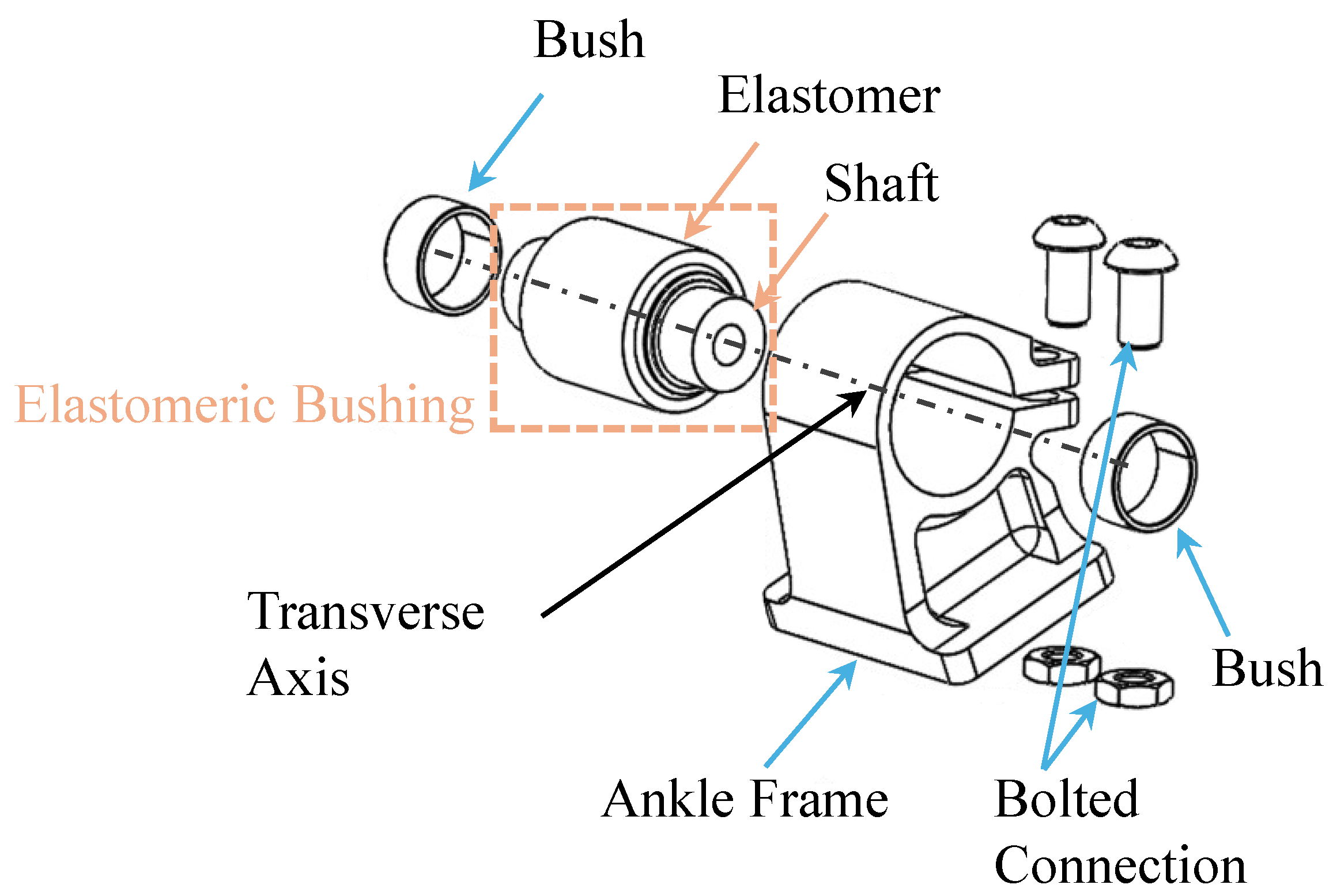
MyFlex-η (Figure 1a), representing an evolution of MyFlex-δ (Figure 1b), comprises two primary sub-assemblies: the foot portion and the main body. The first consists of three CFRP leaf springs (upper, middle, and lower blades), interconnected by two metatarsal bolted joints, and a spring holder secured with the same joint onto the middle blade. The latter includes the novel multi-axial ankle joint, and the tube connector is linked to the shank via a pyramid adapter. These sub-assemblies are assembled through two screws connecting the ankle frame to the upper blade and through the two uni-ball at the link extremities, which create two spherical joints with the tube connector and the spring holder. The design of the multi-axial ankle joint was inspired by an anti-vibration bushing commonly used in automotive suspension systems. Typically, it consists of two concentric hollow metal cylinders connected by an elastomeric insert ring. The elastomer may either be bonded to both cylinders or attached to the inner cylinder and pre-compressed by the outer one, with the chosen manufacturing technique influencing the bushing’s stiffness characteristics. In MyFlex-η, the elastomer is melted onto the shaft and secured within the ankle frame (serving as the outer hollow cylinder), screwing two bolted connections (Figure 2). This ankle frame configuration was chosen based on the results obtained from the design of experiments (DOE) presented in Section 2.2. By adjusting bolts’ screwing, the pre-compression applied to the elastomer can be modified, leading to joint stiffnesses adjustments in the three planes of motion.
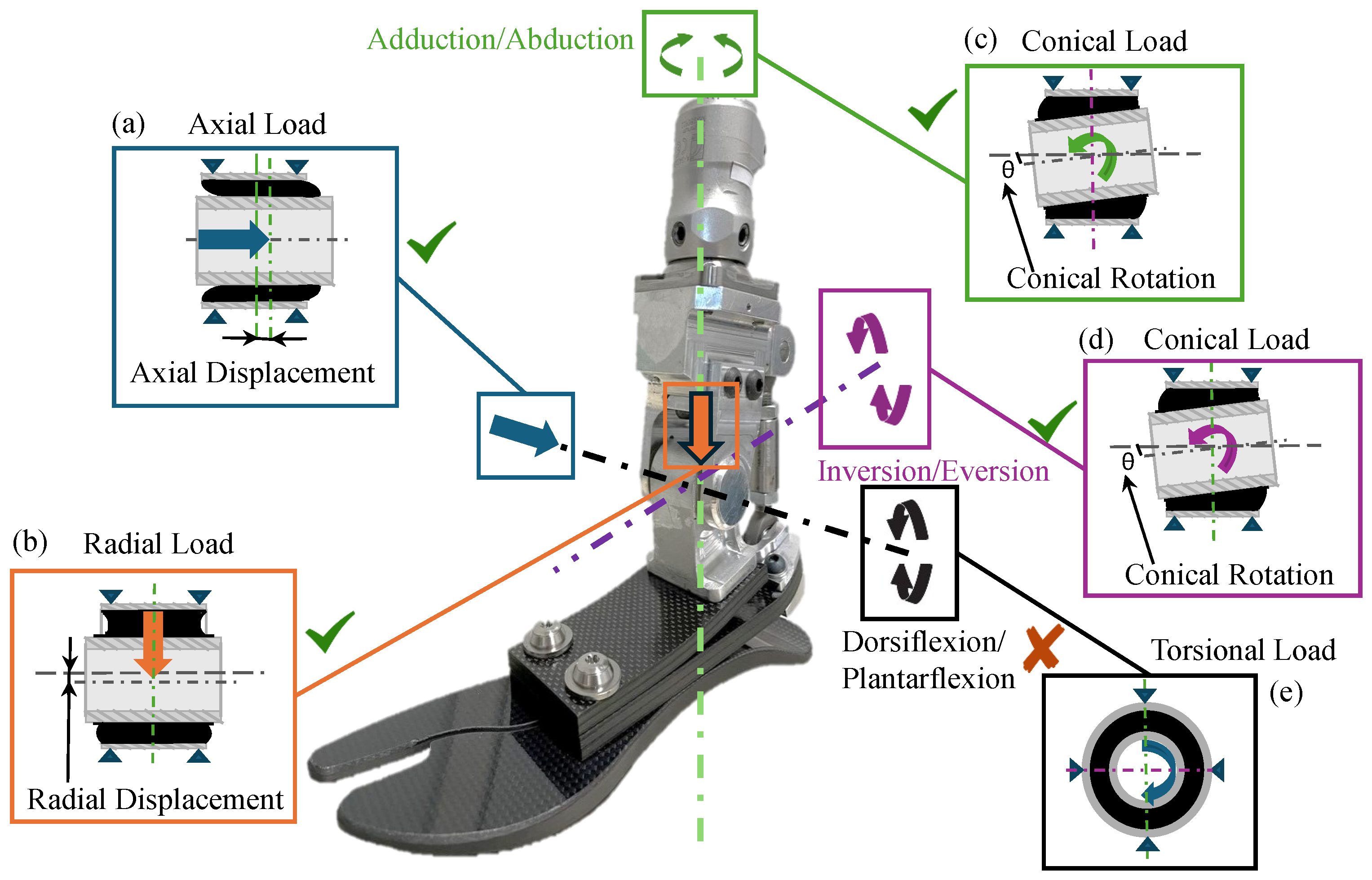
Referring to Figure 3, this design construction allows the equivalent stiffness generated by the torsional stiffness of the leaf spring in series with the bushing’s conical stiffness to govern the prosthesis’ frontal-plane motion. Conical stiffness is determined as the ratio between the conical load and elastomeric bushing conical rotation applied and calculated around the longitudinal axis (Figure 3d). This stiffness also manages the transverse foot rotation, where conical load and bushing rotation are applied and calculated around the vertical axis (Figure 3c).
The hinge connections between the shaft and the tube connector’s arms enable the control of the foot’s sagittal stiffness exclusively through the flexural stiffness of the composite blades, ensuring that no torsional load is applied on the bushing (Figure 3e). Radial stiffness (Figure 3b), defined as the ratio between the vertical load (or radial load) generated during the gait cycle and the vertical displacement (or radial displacement) of the transverse axis, manages foot shock absorption and can modify prosthesis sagittal ROM (as described in Section 2.4). Conversely, axial stiffness (Figure 3a), equal to the ratio between the axial load and the axial displacement of the vertical axis applied along the transverse axis, was set to a specific value to avoid possible ankle misalignment that could have posed risks for the user during gait (as discussed in Section 2.2).

2.2. Design of Experiments of the Multi-Axial Ankle

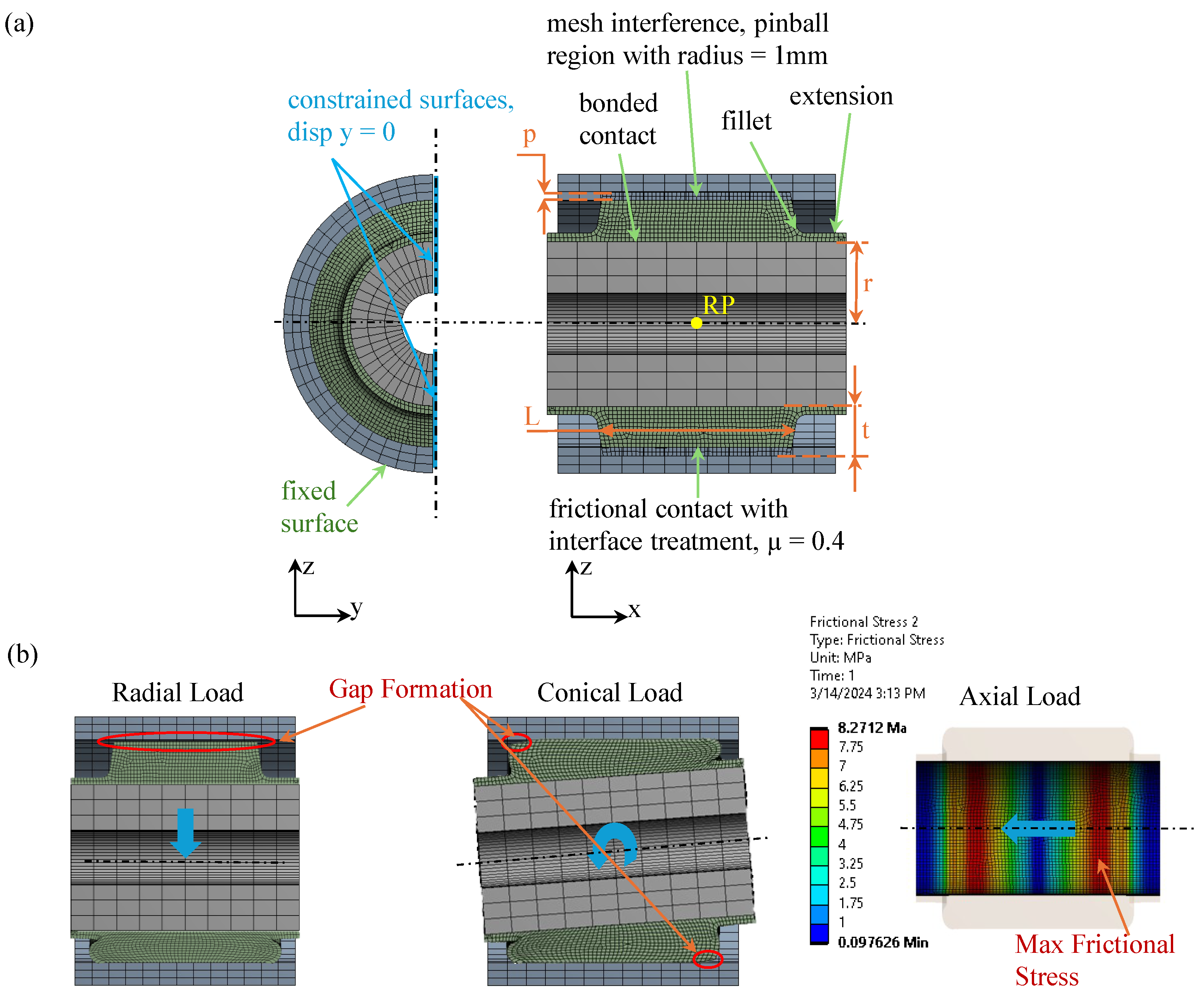
The feasibility of incorporating an elastomeric bushing within the main body of MyFlex-η was investigated through a DOE using finite element (FE) analysis (FEA) with ANSYS Workbench 2023. To streamline the computational efficiency, a half-bushing model (Figure 4a) was imported from a CAD environment, exploiting load and geometry symmetry, and linear material conditions were assumed instead of hyper-elastic properties.
Poisson’s ratio and density for the elastomer were, respectively, set to 0.49 g/cm3 (semi-not-compressible solid) and 1.12 g/cm3.
The A.N. Gent equation (Equation (1)) was employed to establish a correlation between the Shore A hardness (ShA) of the hyper-elastic material and the Young’s Modulus as follows:
E = 0.0981 ( 56 + 7.62336 ShA ) 0.137505 ( 254 2.54 ShA ) ,
The trapezoidal section of the elastomer, along with its 1 mm thick filleted extensions on both sides, was deliberately engineered to alleviate the initial stress generated at the bonding interface with the shaft during the pre-compression phase and to extend the bonding surface.
The pre-compression was modelled as the interference between the external radius of the elastomer and the internal radius of the external hollow cylinder and applied through a frictional contact (pure penalty formulation and friction coefficient = 0.4), with a ramped effect in the interface treatment of geometry modification. Consequently, a bonded connection was established between the elastomer and the shaft (Augmented Lagrange formulation). The outer surface of the external hollow cylinder was fixed to represent the constraint with the ankle frame. Symmetry was simulated by constraining the displacement of the bushing’s sectioned areas along the y-direction. All components were modelled using quadratic displacement behaviour 3D elements with 20 nodes (SOLID 186). Working conditions were replicated by applying loads in the centre-of-gravity point of the shaft by using a rigid remote point (RP). A mesh convergence test was conducted to minimize stress error. The internal and external bushing cylinders were discretized with a coarse mesh, whereas a finer mesh was employed for the elastomer, given its significantly higher compliance than the metal cylinders (approximately four orders of magnitude).
Non-linear simulations were conducted under static structural conditions using a direct solver, with the elastomer’s pre-compression and load application simulated in the first and second steps, respectively. Then, 5° of rotation around the y-axis ( R P y rot ), 1 mm of displacement along the z-axis ( R P z disp ), and 1 mm of displacement along the x-axis ( R P x disp ) were applied at the remote point, separately. Conical ( K con ), radial ( K rad ), and axial ( K ax ) stiffness were determined as the ratios between displacements and fixed support reaction moments and forces according to the following equations (Equations (2)–(4)):
K con = M y R P y rot ( N m o )
K rad = F z R P z disp ( N mm )
K ax = F x R P x disp ( N mm )
The bushing’s parameters (Figure 4a) were systematically varied to evaluate their impact on its mechanical properties. Maximum geometric parameter values were constrained by functional requirements to match human ankle dimensions and ensure the compatibility of the main body with the foot cosmetic cover. Minimum geometrical parameter values were defined based on the loads extrapolated from MyFlex-δ simulations carried out considering the ultimate static test strength condition for a P5 category prosthesis (according to [29], www.iso.org (accessed on 15 June 2021)). Five values for each parameter were explored within predefined limits (Table 1).
The undesirable positioning of the centre of pressure (COP) during gait, attributed to ankle misalignment, poses a risk of reduced user confidence or even falls [30,31,32]. Therefore, constraints were applied to avoid ankle misalignment with respect to the vertical axis of the prosthesis, arising from excessive axial displacement and material strength limitations: gap formation between the elastomer and the outer hollow cylinder, resulting from conical and radial loading (Figure 4b), was limited to zero; the frictional stress (FS) at the bonding interface between the elastomer and the shaft was kept below the permissible value of 9.4 MPa (determined from the validation of the FE model with experimental displacing force tests) to prevent elastomer detachment from the shaft (Figure 4b). Furthermore, considering the axial reaction force generated in the ankle experienced from the cross-slope simulations conducted on MyFlex-δ under the aforementioned load conditions, ankle stiffness was confined within a range of 1200 to 1600 (N/mm) to ensure axial displacement remained below 1 mm.
A regression analysis was employed to fit the results carried out from a total of 9375 simulations (computational time of 15 min for each simulation, using four microprocessor cores) and investigate the relationships between parameter variation with the output and constraints. The regression coefficients ( β i ) of the response surface (Equation (5)) were determined using the least squares method knowing the outputs ( Y i ) obtained from FEAs and the matrix of the five levels of the independent parameters [33] as follows:
Y i = β 0 + β 1 p + β 2 r + β 3 E + β 4 t + β 5 L + β 6 p 2 + β 7 r 2 + β 8 E 2 + β 9 t 2 + β 10 L 2 + β 11 p r + β 12 p E + β 13 p t + β 14 p L + β 15 r E + β 16 r t + β 17 r L + β 18 E t + β 19 E L + β 20 t L
Fitted response surface vectors ( Y fit ) were computed, and non-significant regression coefficients by the analysis of p values associated with each parameter and Pareto charts were excluded. Subsequently, the adjusted coefficients of multiple determination R 2 , assessing the model’s reliability, were found to be 0.9905, 0.9945, and 0.9994, respectively, for conical, radial, and axial stiffness. For simplicity, response surface vectors were reported only for stiffness outputs, as follows (all other vectors with the complete sensitivity analysis are provided in the Supplementary Material):
K con = 3.16 + 2.09 p 0.31 r 0.47 E + 1.18 t 0.71 L + 0.32 t 2 + 0.03 L 2 + 0.04 r E 0.13 r t + 0.05 r L 0.1 E t + 0.05 E L 0.16 t L
K rad = 8150 + 4622.5 p + 28.1 r + 72.9 E 367 t + 506.9 + 821.8 t 2 + 66.8 r E 281.3 r t + 68.8 r L 249.4 E t + 60.1 E L 250 t L
K ax = 138.6 + 79.1 p + 1.6 r + 2.9 E 14.3 t + 5.6 L + 41.9 t 2 + 7.8 r E 19 r t + 4.7 r L 17.5 E t + 5.1 E L + 10.6 t L
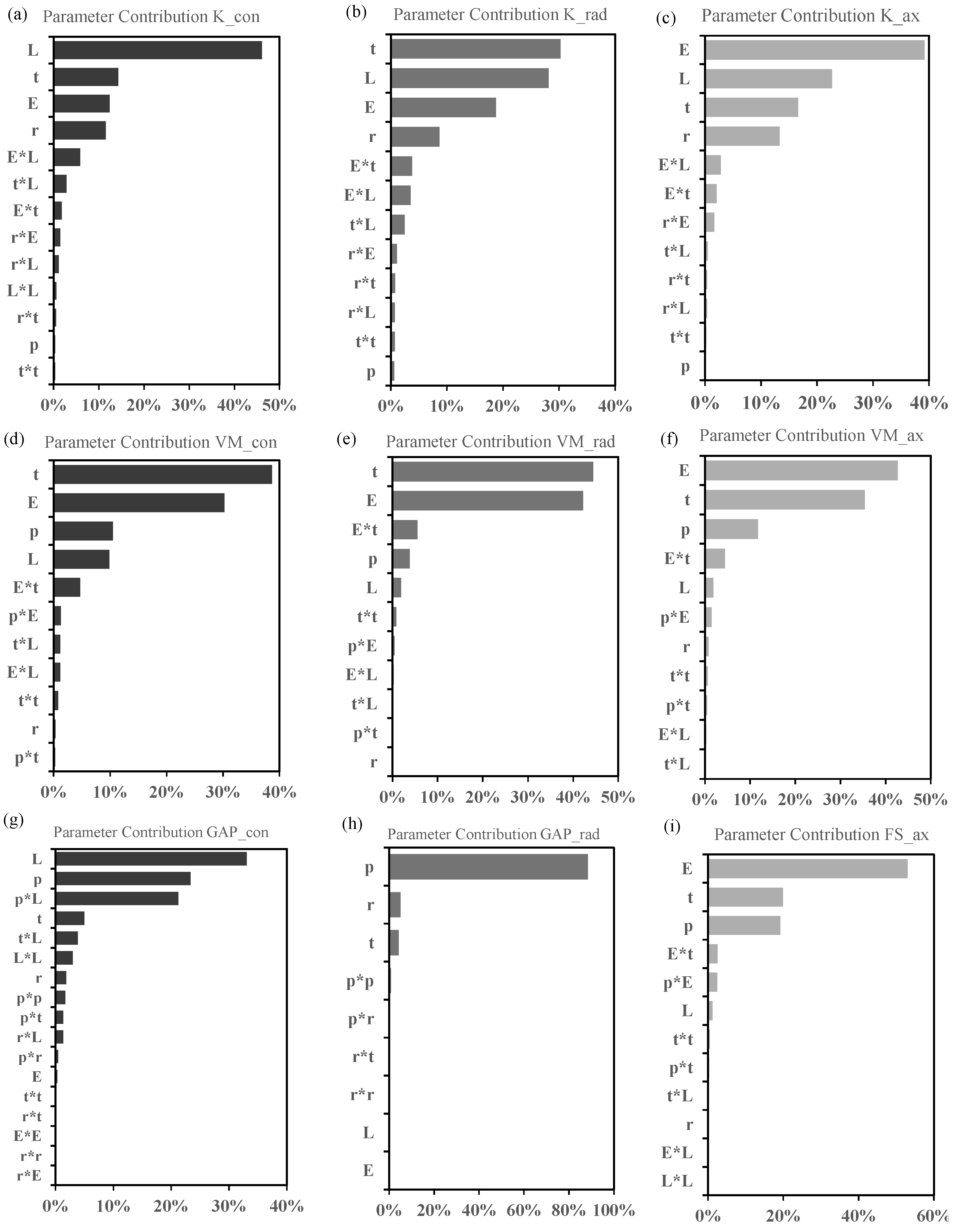
The bar charts in Figure 5 illustrate the parameters’ contributions to the bushing properties. Concerning stiffnesses, the elastomer length (L) had the greatest impact on the conical stiffness, and elastomer thickness (t) predominantly influenced radial stiffness, while the Young’s Modulus mainly affected the axial stiffness. Based on the contribution percentages and regression coefficient signs, an increase in L resulted in a differential increase in stiffnesses, whereas an increase in thickness led to a reduction in stiffnesses, along with a beneficial effect on the stresses developed in the elastomer.
With a clear perspective of parameter sensitivity, the bushing configuration was selected with the aim of replicating the sagittal stiffness and biomechanical behaviour of MyFlex-δ, while also enhancing its adaptation to cross-slopes. Radial stiffness was set to be greater than 9000 (N/mm), since 2D ISO 10328 cyclic simulations (ISO 10328, www.iso.org) performed on MyFlex-η (Section 2.4) revealed the prosthesis ROM increased with bushing radial compliance. Differently, conical stiffness was chosen to obtain a foot frontal rotation greater than 8 degrees, as recommended by AOPA guidelines (AOPA, www.aopanet.org), considering that an ESR foot with a split keel can reach almost 2.5/4.5 degrees [15,23]. In conclusion, due to the high strength constraints identified in the DOE and the fused deposition modelling (FDM) technology adopted to manufacture the elastomeric ring, the Filaflex 82A filament by RECREUS was chosen. The final geometric configuration, determined by considering the Filaflex Young’s Modulus strength of 22 MPa and 45 MPa, respectively (www.recreus.com/filaments/9-filaflex-82a.html (accessed on 23 April 2022)), comprised the following parameters and mechanical properties: p = 0.8 mm, r = 8 mm, E = 22 MPa, t = 5 mm, L = 19 mm, K con = 5.19 (Nm/o), K rad = 10,609 (N/mm), and K ax = 1614.3 (N/mm).

2.3. ISO 10328 and Cross-Slope Adaptation Test Simulations

Once the bushing configuration was defined, the methodology proposed by Tabucol et al. [34] was adopted to finalize the design of the entire foot prosthesis.
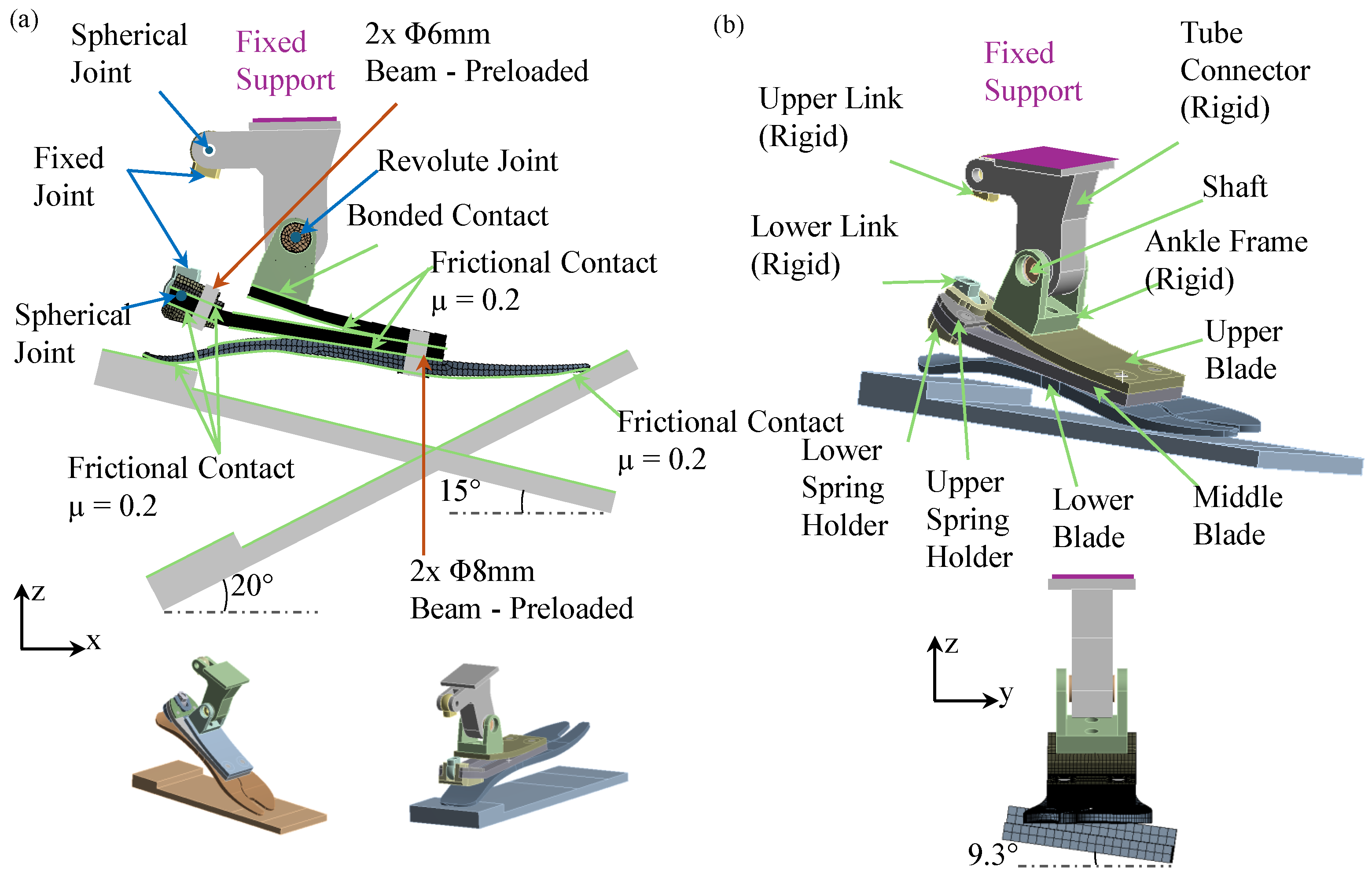
The 2D blade geometries of MyFlex-η mirrored those of MyFlex-δ, since one of the authors’ aims was to enable independent adjustments of stiffness and biomechanical attributes in the frontal and transverse planes and keep the same sagittal stiffness of MyFlex-δ. Consequently, 3D finite element analysis (FEA) was directly employed to determine the stacking sequences of the middle and upper blades (with the lower blade provided by Ossur). Specifically, the ISO 10328 static test (Figure 6a) and a static cross-slope adaptation test (Figure 6b) were replicated in ANSYS Workbench to achieve the desired stiffness category and strength objectives. In the ISO 10328 static tests, the forefoot and heel were independently compressed by applying vertical displacement to a platform, inclined at 15° backward for the plantarflexion test and 20° forward for the dorsiflexion test relative to the ground, which was free to move longitudinally. In a cross-slope adaptation test, the platform loads the entire sole with an inclination on the frontal plane of +9.3° for inversion and −9.3° for eversion.
Upon the definition of the stacking sequence (5 simulations required, each with a computational cost of 8 h, utilizing 8-core processors), an ankle frame and tube connector were designed through different 3D FE models. Such FE models were built replicating critical load schemes defined by reaction forces generated within MyFlex-η FE simulations. Parts were designed considering a safety factor of 2 and a fatigue strength of the aluminium 7075-T6 (160 MPa). Foot prosthesis models were also used to perform simulations considering a rigid elastomer to understand the multi-axial bushing’s contribution to foot static stiffness behaviour.

2.4. Functionality Verification

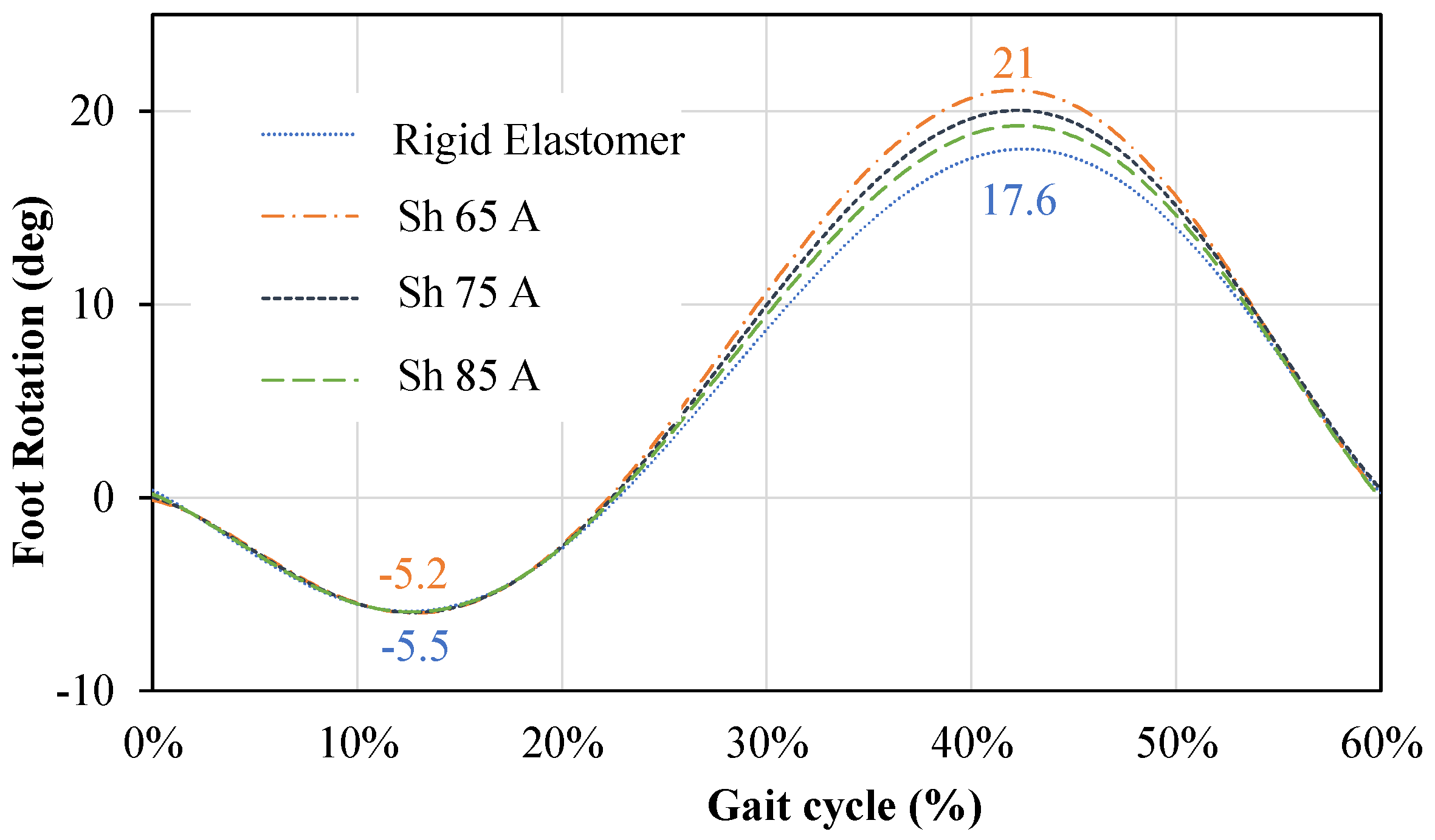
Two-dimensional FEA was exclusively used to verify the influence of the bushing’s radial compliance on the prosthesis ROM. A 2D FE model replicating a single gait cycle, as outlined in ISO 10328, was consequently built (Figure 7a). The simulations were conducted by applying, through the inclined platforms, the same ground reaction forces (GRFs) (calculated considering a user body weight (BW) of 100 kg, Figure 7b) at the heel and forefoot of the prosthesis. The elastic elements of the foot portion were assumed to have identical flexural stiffness, while variations in the elastomer material properties were explored. These variations involved transitioning from a rigid configuration to elastomer with different Young’s Modulus values (E), calculated using Equation (1) for shore hardness values of 65, 75, and 85 ShA. The overall rotation of the foot was subsequently calculated as the variation in the inclination of the orange line defined by the H-M markers with respect to the horizontal black line.
Each of the four simulations necessitated 5 min of computational time, leveraging 8-core processors. The analysis of foot sagittal rotation (Figure 8) unveiled a notable fluctuation in the maximum dorsiflexion angle for bushings with higher compliance, whereas plantarflexion remained largely consistent across all configurations. As previously referenced in Section 2.2, this analysis was conducted to establish a constraint on the radial stiffness of the bushing, aiming to emulate the sagittal biomechanical characteristics, i.e., ROM, of MyFlex-δ.

2.5. Testing Method

The designed elastomeric bushing was manufactured (Figure 9a) together with three distinct test setups. The selection of these test setups was guided by the need to evaluate the elastomeric bushing’s stiffness and strength under radial, conical, and axial loading conditions, as predicted by FEA. These specific loads represent the forces the bushing would encounter during use of the prosthetic foot. Referring to the bushing, the elastomeric part was firstly 3D printed in two halves and then mounted on the shaft. All the parts were assembled inside a mould and placed in an oven at 200 °C for 15 min to melt the elastomers on the shaft. Subsequently, the bushing was pre-compressed inside an ankle frame interfaced with a load cell (Figure 9b) through the bolted connections (Figure 2), adhering to the DOE results. In the radial test (Figure 9b), the hollow shaft of the bushing was compressed by two parallel supports connected to the piston of a hydraulic press machine (INSTRON 8033, 825 University Ave, Norwood, MA, USA). In the conical test (Figure 9c), a lever was inserted into the hollow shaft and loaded at a specific distance to primarily induce a bending effect. In the axial test, the ankle joint was positioned on top of a holed plate (Figure 9d), and its internal shaft was subjected to axial loading using a pin. To ensure accuracy and repeatability, tests were conducted three times for each loading condition by controlling the displacement of the piston and measuring the reaction force using a load cell mounted on top of the machine. This precise control and measurement ensured that the applied loads and resulting displacements were accurately recorded. The testing equipment, including load cells and displacement sensors, were regularly calibrated to ensure their accuracy, minimizing measurement errors and ensuring the reliability of the data collected.
Furthermore, it was considered that errors due to the compliance of the setup were negligible, as materials with stiffnesses four orders of magnitude greater than that of the elastomer were used to manufacture the bushing.
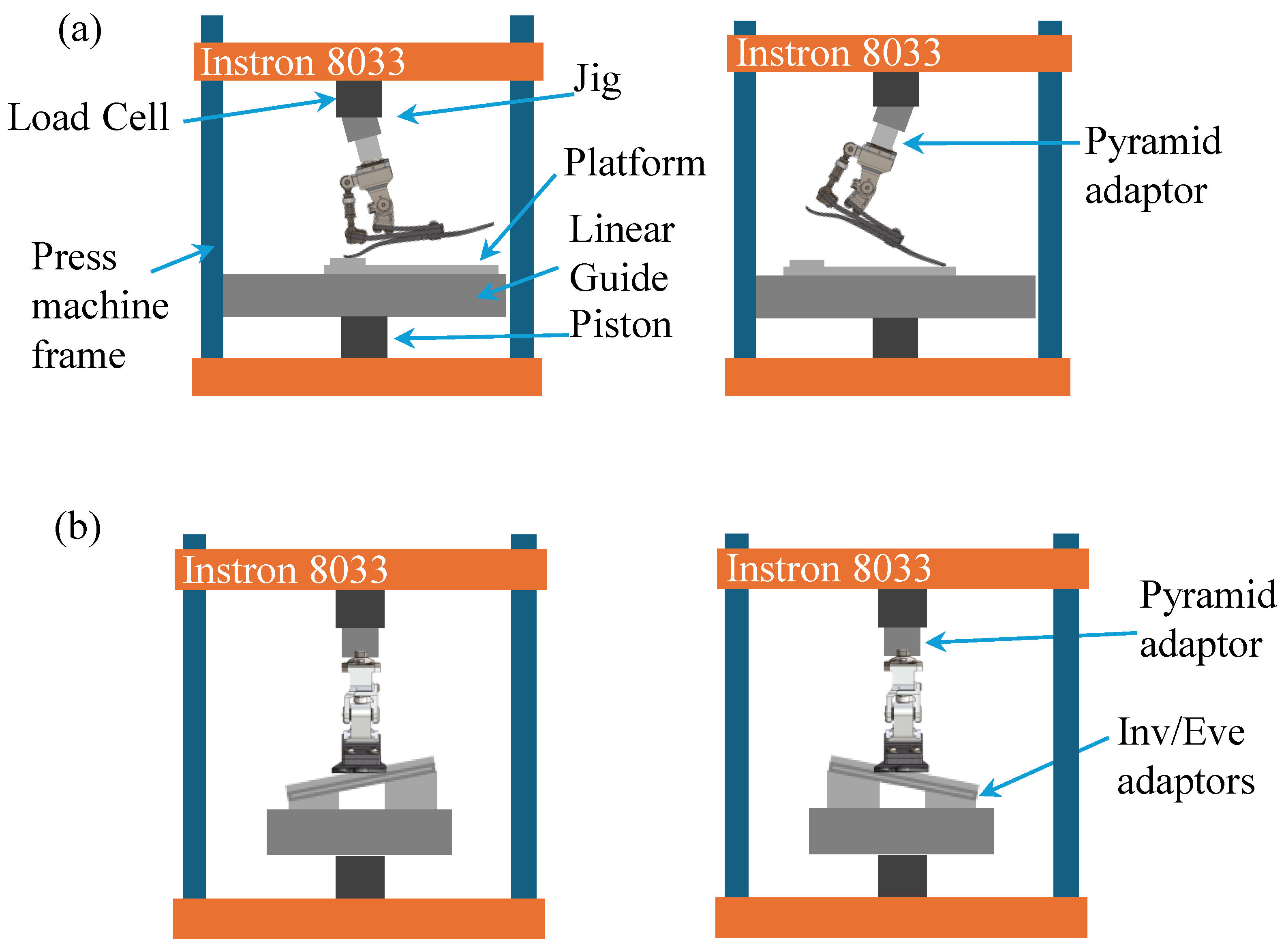
A MyFlex-η prototype was then manufactured and characterized through equivalent ISO 10328 and cross-slope adaptation test setups. Experimental curves depicting the relationship between the reaction force measured by the load cell and vertical platform displacement for the ISO 10328 (Figure 10a) tests were plotted and compared with the results obtained from 3D FEAs. Concerning the cross-slope adaptation tests, markers were positioned on the foot prosthesis keel to evaluate frontal foot rotations in relation with the load measured by the load cell (Figure 10b).

3. Results

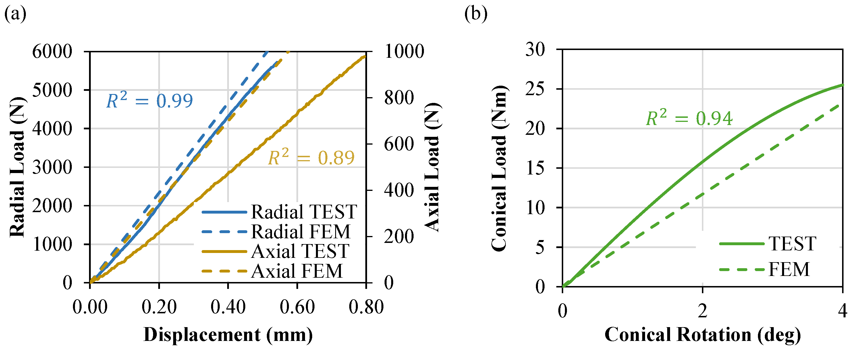
The test results, both for the bushing and the entire prosthesis, were compared with the corresponding results from FEAs to verify the numerical models’ reliability. For the bushing radial and axial cases, the reaction force measured by the load cell was plotted against the imposed displacement of the piston (Figure 11a). Meanwhile, in the conical test, the bending moment was plotted against the conical rotation (Figure 11b).
The coefficient of multiple determination was calculated for each loading condition. The observed mismatch, primarily highlighted in the conical and axial stiffness curves ( R con 2 = 0.94 , R rad 2 = 0.99 and R ax 2 = 0.89 ), can be attributed to the elastomer linear material properties used and rigid adhesive contact modelling between the elastomer and shaft. Nevertheless, no gap formation was observed during the radial and conical test, and no detachment was obtained at the bonding interface under critical axial loading conditions. The final bushing stiffnesses and standard deviation obtained were K con = 6.22 (Nm/o) with std = 0.15 (Nm/o), K rad = 10,201 (N/mm) with std = 725 (N/mm), and K ax = 1167.5 (N/mm) with std = 97 (N/mm).
Prosthesis experimental test curves exhibited notable similarity to the numerical simulations (Figure 12), particularly in relation to the ISO 10328 static test conducted (Figure 12a). Moreover, no discernible disparities were observed between the 3D FEA NB curves, which represented the foot configuration simulated with a rigid elastomer and those associated with the multi-axial foot configuration. Further experimentation with a rigid elastomer integrated within the ankle was deemed unnecessary to corroborate the minimal influence of elastomer compliance on the stiffness characteristics of the prosthesis, given the satisfactory correspondence achieved for the bushing under radial load conditions.
Conversely, the bushing incorporation resulted in an increase of 414% in the prosthesis’ frontal-plane compliance. Specifically, comparing the overall rotation of the prosthesis’ keel by analyzing marker displacement, the prosthesis tested with and without the bushing demonstrated a frontal rotation of 7.2 degrees and 1.4 degrees, respectively (Figure 12b). The discrepancy observed in the conical stiffness of the bushing (Figure 9b), attributed to the elastomer linear properties, was also evident in the initial part of the torsional stiffness curves of the foot. Nevertheless, the maximum errors observed between FEA and the experimental results remained below 10% under a load application of 100 kg (Figure 13).

4. Discussion

Advantages linked with integrating a single DOF joint on each ankle’s motion plane of the prosthesis were observed in previous research [2,3] in terms of enhanced ROM and better adaptation on uneven terrain with a consequent reduction in lateral forces applied on the user stump. Commercial ESR prostheses, in fact, include different features to improve multi-axiality in an attempt to reach such benefits. Continuous forefoot feet, for example, are assembled with elastic elements realized with a lamination sequence that comprises both CFRP or GFRP or a present partial cut along their longitudinal axes (split geometries) to improve torsional compliance in the frontal plane. External modules can be mounted between the foot and shank to improve shock absorption and reduce torsional stress due to excessive frontal and transverse foot stiffnesses. Moreover, the Triton Side Flex includes an ankle joint realized with a torsion bar with its axis placed along the longitudinal axis of the prosthesis to improve cross-slope adaptation, reaching frontal plane rotation greater than 8 degrees. However, a lack of ESR foot prostheses that integrate an ankle with three DOFs is evident.
This study presents the development of an ESR foot, MyFlex-η, featuring a novel multi-axial ankle joint, based on an elastomeric bushing. The primary objective of this research was to introduce a methodology for designing a customizable multi-axial ankle capable of independently adjusting stiffness across the three ankle motion planes. An FEA DOE was employed, and the elastomeric bushing geometric and material parameters were varied to reach the stiffness and strength targets in all ankle motion planes defined considering ISO standards and AOPA and literature guidelines. The MyFlex-η foot presented as a case study in this paper was designed and built upon MyFlex-δ, an ESR foot prosthesis with a CFRP spherical ankle joint, with the scope to improve its multi-axiality but maintain its stiffness and biomechanical behaviour on the main plane of locomotion. In particular, the bushing’s conical stiffness was designed to manage ankle motion in frontal and transverse planes instead of using an external shock absorber [3], thereby also reducing stump stresses [15,22,23]. Experimental tests performed on the elastomeric bushing generally demonstrate the reliability of the numerical models used and confirm the efficacy of the methodology used to design the multi-axial ankle. The final bushing experimental stiffnesses and standard deviations obtained were equal to K con = 6.22 (Nm/o) with std = 0.15 (Nm/o), K rad = 10,201 (N/mm) with std = 725 (N/mm), and K ax = 1167.5 (N/mm) with std = 97 (N/mm). Meanwhile, the coefficients of multiple determination calculated between experimental and numerical results for each loading condition were equal to R con 2 = 0.94 , R rad 2 = 0.99 and R ax 2 = 0.89 . To further enhance the methodology, reduce the error obtained in axial loading conditions and better predict the conical bushing behaviour, future iterations could explore utilizing viscous–elastic material properties and modelling adhesive contact between the elastomer and shaft, albeit at the cost of increased computational complexity. Nonetheless, the proposed methodology can be readily applied to modify both the geometry and materials, allowing for tailored adjustments of the ankle stiffness according to specific user needs. Additionally, different materials could be combined to independently adjust the conical stiffness in the frontal and transverse planes. In conclusion, the results comparing the biomechanical behaviour of MyFlex-η and MyFlex-δ in the sagittal plane and the cross-slope adaptation test are presented in Table 2. As observed, the ROM in the sagittal plane is approximately the same, while performances of MyFlex-η have been improved by 43–44% in cross-slope adaptation motions with respect to MyFlex-δ.

5. Conclusions

In this study, a systematic methodology for designing a customizable multi-axial ankle utilizing an elastomeric bushing was proposed by the authors. A multi-variable regression model was employed to analyse the outputs obtained from DOE conducted through non-linear numerical simulations, aiming to predict bushing stiffnesses across the three ankle planes of motion. Subsequently, FEAs were conducted to develop an ESR prosthetic foot incorporating the novel multi-axial ankle. Experimental tests demonstrated good agreement with numerical simulation predictions, although refinements to the FE model could enhance reliability. Importantly, the implementation of the multi-axial ankle resulted in a substantial 414% increase in frontal-plane compliance when compared to results obtained with the same prosthesis with only one DOF on the sagittal plane. Overall, the DOE also underscored the influence of elastomer pre-compression, the sole parameter adjustable in real time, and the inter-relationship between parameters on bushing properties. Consequently, by designing an elastomeric ring combining various elastomer materials and adjusting pre-compression in real time via bolted connections, users could have the flexibility to tailor the multi-axial behaviour of the foot according to their requirements. These promising mechanical outcomes hold the potential to enhance user comfort and warrant validation through future clinical investigations. Additionally, employing FEM and mechanical tests to replicate dynamic loading conditions on the frontal plane [35] (www.iso.org, 30 May 2021) could provide valuable insights into ground reaction forces and moments transmitted to the user’s stump [22,23]. However, while computerized simulations offer advantages for preliminary studies, further human investigations remain imperative for assessing clinical significance.

Supplementary Materials

Supplementary file “DOE regression analysis” can be downloaded at: https://www.mdpi.com/article/10.3390/prosthesis6040051/s1; file includes Finite Element Analysis Design of Experiments results and regression analysis. All the other datas are contained within the article.

Author Contributions

Conceptualization, M.L. and T.M.B.; methodology, M.L., T.M.B. and J.T.; validation, M.L. and T.M.B.; formal analysis, M.L.; investigation, M.L., T.M.B. and J.T.; data curation, M.L.; writing—original draft preparation, M.L.; writing—review and editing, M.L., T.M.B. and J.T.; visualization, M.L. and T.M.B.; supervision, T.M.B.; project administration, A.Z.; funding acquisition, A.Z. All authors have read and agreed to the published version of the manuscript.

Funding

This work was supported by the European Union’s Horizon 2020 Research and Innovation Programme—“MyLeg” (No. 780871, 2018).

Institutional Review Board Statement

Not Applicable.

Informed Consent Statement

Not Applicable.

Data Availability Statement

Results of Finite Element Analysis Design of Experiments presented in the Section 2.2 “Design of Experiments of the Multi-Axial Ankle” are included in the Supplementary Materials.

Acknowledgments

The authors want to thank Marcello Pauletti and Alexandru Sorin Iacob (MSc students at the University of Bologna) for their contributions to the manufacturing and testing of MyFlex-η. The authors want also to thank Stefano Monti and Roberto Budini (DIN Technicians at the University of Bologna) for their fundamental contributions to the realization of the prototypes. The first author extends sincere thanks, with a special mention to his brother, Andrea Leopaldi, for being a continual source of inspiration and strength in daily life.

Conflicts of Interest

The authors declare no conflicts of interest. The funders had no role in the design of the study; in the collection, analyses, or interpretation of data; in the writing of the manuscript, or in the decision to publish the results.

References

  1. Klute, G.K.; Kallfelz, C.F.; Czerniecki, J.M. Mechanical properties of prosthetic limbs: Adapting to the patient. J. Rehabil. Res. Dev. 2001, 38, 299–307. [Google Scholar]
  2. Heitzmann, D.W.W.; Salami, F.; De Asha, A.R.; Block, J.; Putz, C.; Wolf, S.I.; Alimusaj, M. Benefits of an increased prosthetic ankle range of motion for individuals with a trans-tibial amputation walking with a new prosthetic foot. Gait Posture 2018, 64, 174–180. [Google Scholar] [CrossRef]
  3. Su, P.; Gard, S.A.; Lipschutz, R.D.; Kuiken, T.A. The effects of increased prosthetic ankle motion on the gait of persons with bilateral transtibial amputations. NIH Am. J. Phys. Med. Rehabil. 2010, 89, 34–47. [Google Scholar] [CrossRef]
  4. Hendershot, B.D.; Wolf, E.J. Three-dimensional joint reaction forces and moments at the low back during over-ground walking in persons with unilateral lower-extremity amputation. Clin. Biomech. 2014, 29, 235–242. [Google Scholar] [CrossRef]
  5. Iosa, M.; Paradisi, F.; Brunelli, S.; Delussu, A.S.; Pellegrini, R.; Zenardi, D.; Paolucci, S.; Traballesi, M. Assessment of gait stability, harmony, and symmetry in subjects with lower-limb amputation evaluated by trunk accelerations. J. Rehabil. Res. Dev. 2014, 51, 623–634. [Google Scholar] [CrossRef]
  6. Lee, W.C.; Zhang, M.; Mak, A.F. Regional differences in pain threshold and tolerance of the transtibial residual limb: Including the effects of age and interface material. Arch. Phys. Med. Rehabil. 2005, 86, 641–649. [Google Scholar] [CrossRef]
  7. Highsmith, M.J.; Kahle, J.T.; Klenow, T.D.; Andrews, C.R.; Lewis, K.L.; Bradley, R.C.; Ward, J.M.; Orriola, J.J.; Highsmith, J.T. Interventions to manage residual limb ulceration due to prosthetic use in individuals with lower extremity amputation: A systematic review of the literature. Technol. Innov. 2017, 18, 115–123. [Google Scholar] [CrossRef]
  8. Glaister, B.C.; Bernatz, G.C.; Klute, G.K.; Orendurff, M.S. Video task analysis of turning during activities of daily living. Gait Posture 2007, 25, 289–294. [Google Scholar] [CrossRef]
  9. Ficanha, E.M.; Rastgaar, M. Preliminary design and evaluation of a multi-axis ankle-foot prosthesis. In Proceedings of the 5th IEEE RAS/EMBS International Conference on Biomedical Robotics and Biomechatronics IEEE, Sao Paulo, Brazil, 12–15 August 2014; pp. 1033–1038. [Google Scholar]
  10. Dixon, P.C.; Pearsall, D.J. Gait Dynamics on a Cross-Slope Walking Surface. J. Appl. Biomech. 2010, 26, 17–25. [Google Scholar] [CrossRef]
  11. Damavandi, M.; Dixon, P.C.; Pearsall, D.J. Kinematic adaptations of the hindfoot, forefoot, and hallux during cross-slope walking. Gait Posture 2010, 32, 411–415. [Google Scholar] [CrossRef]
  12. Madusanka, D.G.K.; Wijayasingha, L.N.S.; Sanjeevan, K.; Ahamed, M.A.R.; Edirisooriya, J.C.W.; Gopura, R.A.R.C. A 3DOF transtibial robotic prosthetic limb. In Proceedings of the 7th International Conference on Information and Automation for Sustainability, Colombo, Sri Lanka, 22–24 December 2014; IEEE: Piscataway, NJ, USA, 2014; pp. 1–6. [Google Scholar]
  13. Brockett, C.L.; Chapman, G.J. Biomechanics of the ankle. Orthop. Trauma 2016, 30, 232–238. [Google Scholar] [CrossRef]
  14. Moriguchi, C.; Sato, T.; Gil Coury, H. Ankle movements during normal gait evaluated by flexible electrogoniometer. Rev. Bras. Fisioter. 2007, 11, 205–211. [Google Scholar] [CrossRef]
  15. Ernst, M.; Altenburg, B.; Schmalz, T. Characterizing adaptations of prosthetic feet in the frontal plane. Prosthetics Orthot. Int. 2020, 44, 225–233. [Google Scholar] [CrossRef]
  16. Agboola-Dobson, A.; Wei, G.; Ren, L. Biologically Inspired Design and Development of a Variable Stiffness Powered Ankle-Foot Prosthesis. J. Mech. Robot. 2019, 11, 1–15. [Google Scholar] [CrossRef]
  17. Bellman, R.D.; Holgate, M.A.; Sugar, T.G. SPARKy 3: Design of an active robotic ankle prosthesis with two actuated degrees of freedom using regenerative kinetics. In Proceedings of the 2nd Biennial IEEE/RAS-EMBS International Conference on Biomedical Robotics and Biomechatronics (BioRob.), Scottsdale, AZ, USA, 19–22 October 2008; pp. 511–516. [Google Scholar]
  18. Masum, H.; Bhaumik, S.; Ray, R. Conceptual Design of a Powered Ankle-foot Prosthesis for Walking with Inversion and Eversion. Procedia Technol. 2014, 14, 228–235. [Google Scholar] [CrossRef]
  19. Rad, N.F.; Yousefi-Koma, A.; Tajdari, F.; Ayati, M. Design of a novel three degrees of freedom ankle prosthesis inspired by human anatomy. In Proceedings of the 4th RSI International Conference on Robotics and Mechatronics (ICRoM), Tehran, Iran, 26–28 October 2016; pp. 428–432. [Google Scholar]
  20. Tsung-Han Hsieh, B.A. Design and Control of a Two-Degree-of-Freedom Powered Ankle-Foot Prosthesis. Master’s Thesis, Massachussetts Institutes of Technology, Cambridge, MA, USA, September 2019. [Google Scholar]
  21. Maitland, M.E.; Allyn, K.J.; Ficanha, E.; Colvin, J.M.; Wernke, M.M. Finite Element Simulation of Prosthetic Foot Adaptation to Mediolateral-Angled Cross-Slopes. JPO J. Prosthetics Orthot. 2020, 32, 236–244. [Google Scholar] [CrossRef]
  22. Maitland, M.E.; Allyn, K.J.; Ficanha, E.M.; Colvin, J.M.; Wernke, M.M. Finite Element Simulation of Frontal Plane Adaptation Using Full-Foot, Split-Toe, and Cam-Linkage Designs in Prosthetic Feet. J. Prosthetics Orthot. 2022, 34, 14–21. [Google Scholar] [CrossRef]
  23. Wernke, M.M.; Ficanha, E.M.; Thomas, Z.; Maitland, M.E.; Allyn, K.J.; Albury, A.; Colvin, J. Mechanical testing of frontal plane adaptability of commercially available prosthetic feet. J. Rehabil. Assist. Technol. Eng. 2022, 9, 20556683221123330. [Google Scholar] [CrossRef]
  24. Fukuchi, C.A.; Fukuchi, R.K.; Duarte, M. A public dataset of overground and treadmill walking kinematics and kinetics in healthy individuals. PeerJ 2018, 6, e4640. [Google Scholar] [CrossRef]
  25. James Mahoney, M.E.; Stapleton, D.B.; Renner, K.; Puccinelli, A.; Vardaxis, V. Evaluation of the subtalar joint during gait using 3-D motion analysis: Does the STJ achieve neutral position? Foot Ankle Online J. 2019, 12, 157–163. [Google Scholar]
  26. Fogelberg, D.J.; Allyn, K.J.; Smersh, M.; Maitland, M.E. What People Want in a Prosthetic Foot: A Focus Group Study. JPO J. Prosthetics Orthot. 2016, 28, 145–151. [Google Scholar] [CrossRef] [PubMed]
  27. Xu, D.; Zhou, H.; Quan, W.; Ma, X.; Chon, T.E.; Fernandez, J.; Gusztav, F.; Kovács, A.; Baker, J.S.; Gu, Y. New Insights Optimize Landing Strategies to Reduce Lower Limb Injury Risk. Cyborg Bionic Syst. 2024, 5, 0126. [Google Scholar] [CrossRef] [PubMed]
  28. Tabucol, J.; Kooiman, V.G.M.; Leopaldi, M.; Brugo, T.M.; Leijendekkers, R.A.; Tagliabue, G.; Raveendranathan, V.; Sotgiu, E.; Benincasa, P.; Oddsson, M.; et al. The Functionality Verification through Pilot Human Subject Testing of MyFlex-δ: An ESR Foot Prosthesis with Spherical Ankle Joint. Appl. Sci. 2022, 12, 4575. [Google Scholar] [CrossRef]
  29. ISO. Available online: https://www.iso.org/standard/38708.html (accessed on 15 June 2021).
  30. Oliveira, L.F.; Simpson, D.M.; Nadal, J. Calculation of area of stabilometric signals using principal component analysis. Physiol. Meas. 1996, 17, 305–312. [Google Scholar] [CrossRef] [PubMed]
  31. Pillet, H.; Bonnet, X.; Lavaste, F.; Skalli, W. Evaluation of force plate-less estimation of the trajectory of the centre of pressure during gait. Comparison of two anthropometric models. Gait Posture 2010, 31, 147–152. [Google Scholar] [CrossRef] [PubMed]
  32. Popovic, M.R.; Pappas, I.P.I.; Nakazawa, K.; Keller, T.; Morari, M.; Dietz, V. Stability criterion for controlling standing in able-bodied subjects. J. Biomech. 2000, 33, 1359–1368. [Google Scholar] [CrossRef]
  33. Montgomery, D.C. Design and Analysis of Experiments, 9th ed.; Wiley: Hoboken, NJ, USA, 2017. [Google Scholar]
  34. Tabucol, J.; Brugo, T.M.; Povolo, M.; Leopaldi, M.; Oddsson, M.; Carloni, R.; Zucchelli, A. Structural fea-based design and functionality verification methodology of energy-storing-and-releasing prosthetic feet. Appl. Sci. 2022, 12, 97. [Google Scholar] [CrossRef]
  35. ISO. Available online: https://www.iso.org/standard/69821.html (accessed on 30 May 2021).
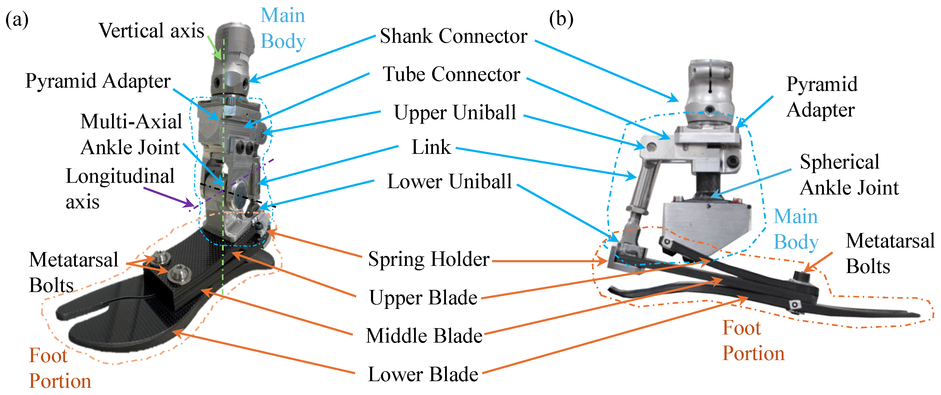
Figure 1. Differences between the MyFlex-η prototype and its predecessor, MyFlex-δ [28]. (a) MyFlex-η features an independent stiffness multi-axial ankle, whereas (b) MyFlex-δ is characterized by a CFRP spherical ankle joint.
Prosthesis 06 00051 g001
Figure 2. Expanded view of the MyFlex-η multi-axial ankle sub-assembly.
Prosthesis 06 00051 g002
Figure 3. Sectional views of the multi-axial ankle joint, accompanied by schematic representations of applicable load conditions. (a) Radial load; (b) conical load around the longitudinal axis; (c) conical load around the vertical axis; (d) axial load; (e) torsional load; schematic representation of which elastomeric bushing stiffness manages ankle motions.
Prosthesis 06 00051 g003
Figure 4. Finite element (FE) modelling of the elastomeric bushing for DOE. (a) Parameters, contact, mesh, and constraints. (b) Critical outputs, obtained from the analysis, monitored to select the optimal configuration of the bushing to integrate within the ankle of the prosthesis.
Prosthesis 06 00051 g004
Figure 5. Parameters’ contributions resulting from the sensitivity analysis: (a) conical stiffness (b), radial stiffness (c), axial stiffness (d), equivalent von Mises stress due to conical load (e), equivalent von Mises stress due to radial load (f), equivalent von Mises Stress due to axial load (g), gap formation due to conical load (h), gap formation due to radial load (i), frictional stress at shaft bonding interface due to axial load. L = elastomer length, t = elastomer thickness, E = Young’s Modulus, p = pre-compression.
Prosthesis 06 00051 g005
Figure 6. MyFlex-η 3D FE models. (a) ISO 10328 static test. (b) Cross-slope test (inversion test illustrated). Elastomeric bushing contacts defined in the DOE were replicated in these models. Pure penalty formulation law was used for all contacts. Preloaded beam joints (BEAM3, ANSYS) were used for the bolted connections. A fixed body-to-body joint connected the upper and lower link parts to replicate the link connector. Spherical body-to-body joints modelled the kinematic spherical joint between the upper uniball of the link and tube connector, as well as between the lower uniball of the link and spring holder. A revolute body-to-body joint modelled the hinge joint formed between the shaft and ankle frame. Composite blades were modelled with a solid element (SOLID185) for each ply through the thickness using Ansys ACP, while all other parts were discretized directly with solid elements. The ankle frame, tube connector, and both lower and upper links parts were modelled as rigid bodies to mitigate computational costs.
Prosthesis 06 00051 g006
Figure 7. MyFlex-η 2D FE model. (a) ISO 10328 cyclic test. (b) Ground reaction forces applied at the heel and forefoot. Elastomeric bushing contacts defined in the DOE were replicated in this model. A cosmetic cover in low-density polyethylene (LDPE) was employed in the 2D CAD model, as suggested by the standard guidelines, and bonded on the lower blade. No separation contact was used to replicate the hinge joint formed between the shaft and tube connector. Pure penalty formulation law was used for all contacts. Preloaded beam joints (BEAM3, ANSYS) were used for the bolted connections. A body-to-body beam joint (BEAM3, ANSYS) connected the tube connector and the spring holder to replicate the link connector. All parts were modelled with a plane element (PLANE182).
Prosthesis 06 00051 g007
Figure 8. MyFlex-η 2D FEA: ISO 10328 cyclic test results related to the stance phase.
Prosthesis 06 00051 g008
Figure 9. (a) Manufactured bushing. (c) Conical setup for conical stiffness characterization, (d) axial setup for axial stiffness characterization. All the setup parts were manufactured in aluminium 7075, apart from the lever, which was realized in C40 steel.
Prosthesis 06 00051 g009
Figure 10. MyFlex-η mechanical test setup characterization. (a) ISO 10328 sagittal equivalent static test setup: the foot fixed on the load cell assembled on top of the hydraulic press machine was compressed by a piston that pushed a platform upward, which was free to move along the foot in a longitudinal direction thanks to a linear guide. Two different jigs were interposed between the prototype and the top of the machine in consideration of foot inclinations described in the standard. (b) Cross-slope adaptation test setup: inclined inversion and eversion adaptors were used to assemble the platform on the piston, providing the required frontal plane slope for frontal plane tests. The foot was directly mounted on the load cell with its longitudinal axis parallel to the ground to assess the ankle rotation.
Prosthesis 06 00051 g010
Figure 11. Bushing experimental test vs. FEA results: (a) radial and axial load test; (b) conical load test.
Prosthesis 06 00051 g011
Figure 12. Foot prosthesis experimental test compared with FEA results. (a) ISO 10328 static test curves: PF = plantarflexion test; DF = dorsiflexion test; NB = no bushing; (b) Cross-slope adaptation test: experimental test rotation calculated at 25, 50, 75, and 100% of load application compared with FEA curves. INV = inversion; EV = eversion; NB = no bushing.
Prosthesis 06 00051 g012
Figure 13. Foot prosthesis cross-slope adaptation static test compared with FEA result: (a) experimental eversion test evaluated at 0 and 100% of load application. (b) FE eversion test at 100% of load application.
Prosthesis 06 00051 g013
Table 1. DOE parameters: pre-compression (p), internal radius (r), Young’s Modulus (E), thickness (t), medium length between short and long edges of the elastomer trapezoidal section (L). The chosen parameters’ values define the DOE design space.
ParameterUnitsValues
Pre-compression (p)mm0.5, 0.6, 0.7, 0.8, 0.9
Radius (r)mm6, 7, 9, 11, 12
Young’s Modulus (E)MPa8, 12, 16, 20, 24
Thickness (t)mm3, 3.5, 4.5, 5.5, 6
Length (L)mm12, 14, 18, 22, 24
Table 2. Main plane of locomotion (sagittal plane), according to ISO 10328, and cross-slope adaptation tests’ comparison between MyFlex-η and MyFlex-δ. D = dorsiflexion, P = plantarflexion, I = inversion, E = eversion.
ProsthesisSagittal PlaneCross-Slope Adaptation
MyFlex-ηD 19 / P 9I 7.2 / E 6.8
MyFlex-δD 20 / P 7I 4.1 / E 3.8
Disclaimer/Publisher’s Note: The statements, opinions and data contained in all publications are solely those of the individual author(s) and contributor(s) and not of MDPI and/or the editor(s). MDPI and/or the editor(s) disclaim responsibility for any injury to people or property resulting from any ideas, methods, instructions or products referred to in the content.