Abstract
The arrangement of a stress breaker in the pier abutment of a fixed-mobile bridge affects the deformations that may occur in its supports. This article aims to study the most appropriate position and arrangement of a stress breaker. To verify the established objectives, an experimental “in vitro” study was carried out with five different bridge designs: one with rigid connectors and four with non-rigid connectors (interlocks), placed on the distal and mesial surface of the intermediate abutment, and combining the retention stop at cervical and occlusal positions. The strain level at the support ground of each bridge was measured with strain gauges. The statistical analysis was performed with the help of the Kruskal–Wallis test and a linear regression model. Initial results show that the model with the highest average value of maximum strain is the non-rigid bridge with the interlock on the distal surface of the pier abutment and the occlusal retention stop. In any case, the presence of an intermediate abutment, with or without interlock, influences the maximum tension supported by the abutment, especially in relation to the intermediate abutment.
1. Introduction
Tooth-supported fixed prosthetic restorations, such as crowns or bridges, are the treatment of choice for the replacement of one or more missing teeth. In the case of bridges, these are preferably built with rigid connectors between the retainers and the pontics, because they provide the prosthesis with the desired solidity and stiffness. At the same time, they minimize the restoration’s overloading [1]. However, a completely rigid fixed restoration is not always suitable for restoring single-tooth gaps separated by an intermediate tooth [2], as in the case of a five-unit bridge with pier abutment.
The reasons why such a bridge is not the ideal treatment are diverse. First of all, because of the curvature of the dental arch, the teeth of the different segments move in different directions. The linguo-labial mobility of an anterior tooth forms a substantial angle with the linguo-buccal mobility of a posterior tooth. These movements, of measurable magnitudes and divergent directions, can create overstrain, which in a long bridge will be transmitted to the terminal abutments, with the intermediate abutment acting as a fulcrum of the lever arm. The transmission of these forces will cause the weaker retainer to fail, causing it to loosen and so lead to marginal leaks and tooth decay, which are usually of a considerable size before they can be discovered. Secondly, the retention offered by an anterior tooth, due to its smaller size, is lower than the one provided by a posterior tooth, so the resistance to forces is remarkably different [1].
A possible way to solve the above-mentioned problems produced by a rigid five-unit bridge with pier abutment is using a non-rigid connector or attachment, also called a stress breaker, which in general is a male/female system that interrupts the transmission of load excess. Although this system may be the solution, there have been no conclusive studies in the consulted literature that really justify the placement or otherwise of stress breakers, nor in what position they should be placed.
Among the stress breakers, we can find the interlock which has a mechanical connection between the retainer and the pontic that is mounted in replacement of the usual rigid welding. This consists of a male or patrix part, which slides into a female or matrix part. The axial path is limited by a stop or rest that is usually located in the cervical region of the female part, but which may be located in the occlusal region of the male. In fixed prosthetic restorations, the non-rigid connectors that can be used are the intracoronal friction grip slide attachments, adjustable or non-adjustable (Figure 1 and Figure 2), which from now on we will refer to as interlocks.
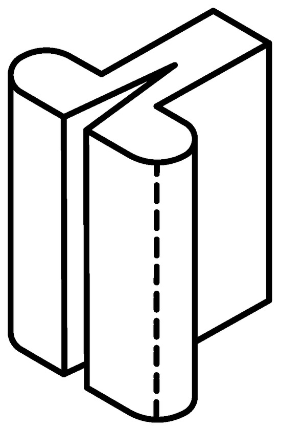
Figure 1.
Intracoronal adjustable friction grip slide attachment.
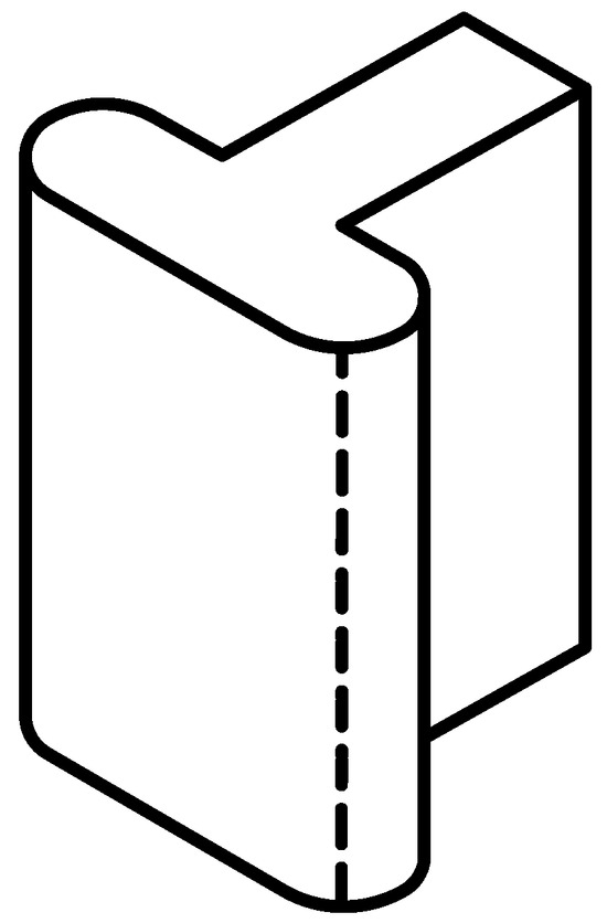
Figure 2.
Intracoronal non-adjustable friction grip slide attachment.
In the former, the male part is split to allow the activation of the friction responsible for the system retention, and depending on the greater or lesser separation that is provided to the activatable blades, the greater or lesser the retention will be. In the latter, since they do not have activatable blades, the frictional force cannot be increased. Nonetheless, the length of the attachment contributes to the distribution of the contact force over a larger surface, thereby enhancing grip.
There is a wide variety of non-rigid connectors. These connectors come in different sizes, both in height and in width or in depth; therefore, before preparing the abutment teeth, the length of these should be measured in a vertical and bucco-lingual direction, in order to choose the one that in height and width best suits the type of abutment we have. The most frequently used forms for interlocks are those of a solid cylinder or a T-shaped rail, which is welded to the pontic and a hollow cylinder or a T-rail housing located in the abutment retainer.
Non-rigid connectors can be made in advance by the manufacturer to be welded or placed in the metal structure or be made with castable patterns to be placed in the dental laboratory. The prefabricated ones are elaborated with precious metals, where the adaptation of the two work elements (male and female) is very intimate and therefore more exact in their construction than those manufactured in the laboratory. Prefabricated precision connectors are presented in different alloys for welding or casting directly on them. The alloys with which they are manufactured are based on gold, platinum, and iridium and allow a good union with conventional precious alloys and with the precious ones used in metal–ceramic structures.
The main application of the non-rigid connectors has been described in bridges of five units with pier abutment, to prevent the said abutment from acting as a fulcrum in a first-generation lever system in the bucco-lingual or occluso-cervical direction [1], thus preventing mechanical or retention failures [3]. There are other frequent applications in clinical practice, such as bridges located in a combination of curved and straight paths, or bridges in which the abutments have different retention values, whether to join, separate, or break sections of bridges in order to overcome the existing difficulties due to the lack of parallelism between abutments, among others.
However, they are not exempt from contraindications, such as long pontic situations, because a long pontic would produce a magnification of the movement, which would in turn be harmful to the extreme abutment. If the abutments show a mobility of some importance [1], a rigid design may be clinically preferable when the abutment teeth have a periodontal decrease, because stress could then be shared more evenly among all the teeth. Finally, when there is no even distribution of forces in any part of the bridge, the male part of the connector and the posterior units, subject to minimal or zero forces, may suffer a tendency to egression [1]; for example, when the posterior abutment or the pontics, or both, have no antagonists or occlude with a removable partial prosthesis, and if the three previous units occlude with natural teeth.
When referring to a fixed prosthetic restoration of five units with a pier abutment, the possible location of a non-rigid connector is not unanimous. Shillingburg [1] and Fisher [4] showed that the non-rigid connector must be placed in the intermediate abutment because if it is placed in a terminal abutment, it would allow the pontic to exert a large lever arm with the pier abutment as a fulcrum (Figure 3).
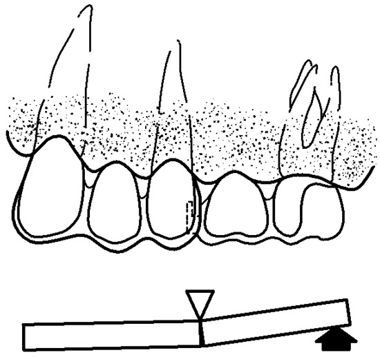
Figure 3.
Interlock on the pier abutment, preventing it from functioning as a fulcrum. Modified from Shillinburg [1].
On the other hand, the female of the non-rigid connector is placed on the distal surface of the intermediate abutment within the normal contour, and the male is placed on the mesial surface of the pontics that replaces the absent distal tooth. The reason for placing them like this is because the longitudinal axes of the posterior teeth have a slight inclination towards mesial, and the occlusal forces applied vertically cause an additional movement in that same direction, and when placed in this way, this movement towards mesial tends to interlock the male solidly in the female. On the other hand, if the female is placed on the mesial surface of the intermediate abutment and the male on the distal surface of the mesial pontics, the male part tends to be expelled during the aforementioned mesial movements.
On the contrary, Landry et al. [5] suggest that stress could break or loosen any terminal retainer but not the intermediate abutment, so that the loads centered on the intermediate abutment are partly supported by the terminal abutments, in such a way that an interlock is not necessary, or at least not in the pier abutment. However, Molding [3] recommended the use of two non-rigid connectors, one on the distal surface of the intermediate abutment and a second, if desired, on the distal surface of the anterior abutment. In another, subsequent research study, but without an intermediate abutment, the same authors propose [6] an alternative to the usual orientation of the non-rigid connector, which consists of placing the male on the distal surface of the anterior abutment and the female in the mesial position of the pontics. In addition to this change, these authors placed the non-rigid connector’s retention stop towards the occlusal region (Figure 4).
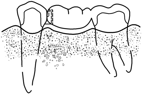
Figure 4.
Interlock with reverse orientation. Female in mesial of the pontic, male in distal of the abutment, and retention stop in occlusal (Modified from Shillinburg [1]).
By using this inverted orientation, they obtained various advantages. First, by placing the male on the distal surface of the abutment, it can be prepared with a smaller reduction to hold the non-rigid retainer, while retaining more tooth. This preservation of dental structure ensures retention, improves the strength of the buttress, and minimizes pulp irritation. Secondly, the non-rigid connector, being completely inside the pontics, allows the overcontouring abutment to be controlled, thus avoiding periodontal problems. Thirdly, the problem with the parallelism of the non-rigid connector for a mesially inclined posterior abutment is solved with this change in orientation, as the male is placed as a small overhang on the distal face of the mesial abutment, while the female is in a more distal position of the pontic.
This inverted orientation allows for more flexibility in the positioning of the connector. And finally, it improves the aesthetics, since the only visual evidence of the connector is the interface between the metallic guide planes of the two segments. However, in spite of the above-mentioned advantages, this change in orientation also results in some disadvantages, such as the fact that the female is far from the longitudinal axis of the abutment, which may cause a distal torque of the abutment. With pontics that contact the mucosa, the space between the male and the female is an area for the retention of bacterial plaque, which can lead to tissue irritation. The latter problem is solved using pontics that do not contact the mucosa, which is not always possible, especially in anterior areas, where aesthetics prevails, and thus, it is necessary to provide the pontic a natural appearance.
Therefore, there are three possibilities with which a fixed prosthetic restoration with pier abutment can be performed and are as follows: with rigid connectors, with non-rigid connectors with the usual orientation placed on the distal surface of the mesial abutment, on the mesial or distal surface of the intermediate abutment or on the mesial surface of the distal abutment, and with non-rigid connector with an inverted orientation.
The non-rigid connector retention, which is usually located in the cervical region of the female part, is an element whose function is to limit the axial travel of the male when it is sliding along the female. In the research carried out by Molding et al. [6], the retention stop was placed in the occlusal region, and the main advantage of which was aesthetic since the only visual evidence of the connector is the interface between the metallic guide planes of the two segments. However, the opening to the gingival surface of the female creates a retention area of bacterial plaque, which can lead to tissue irritation. Nevertheless, in our review of the existing literature, we did not find enough data to justify the placement of the non-rigid connector retention stop in the cervical or occlusal region.
Therefore, the information obtained in our bibliographic review does not reveal or make clear whether the non-rigid design of the fixed partial prosthesis is really favorable or not compared to a rigid design, nor is the most favorable location of the interlock mentioned, nor the situation of its retention stops. The non-rigid interlocks or interlock connectors, in addition to they being used in the construction of fixed prostheses, as we have mentioned above, can also be used in the design of mixed prostheses, overdentures on natural teeth or implants, or in mixed tooth- and implant-supported bridges.
A mixed prosthesis is the combination of a fixed prosthesis and a removable partial prosthesis, whose assembly between them is performed by means of an attachment, precision attachment or non-rigid connector, which is an exact male and female adjustment mechanism, where one portion joins the abutment tooth and another the metal skeleton of the removable partial denture. In general, there is a wide variety of attachments on the market, and new models and designs continue to emerge every day, aiming to improve mechanical performance, together with providing greater ease of use.
However, nowadays, an alternative to the use of tooth-supported fixed prosthetic restorations for the replacement of missing teeth is increasingly the indication of a fixed implant-supported prosthesis. Although, in most cases, the rehabilitation of an edentulous space is carried out by means of a fixed implant-supported prosthesis with no connection to natural teeth, there is also the possibility of prosthetically joining two structures as different as teeth and implants, with a bridge with and without interlock.
When this is performed, it must be taken into account that a natural tooth is surrounded by the periodontal ligament, which provides it resilience to occlusal forces, so that it can compensate for occlusal stress through small movements, and in turn has proprioceptors which play an essential role in the regulation of movements and chewing forces that provides a certain degree of protection to the remaining tooth structure [7,8].
The implant, on the other hand, lacks a periodontal ligament and, consequently, the occlusal forces transmitted to the implant and to the peri-implant bone are traction forces, compression forces, and shear forces. Furthermore, because they have no proprioceptive capacity, they cannot be compensated for [7,8,9].
In this situation, tooth-implant splinting, given the different nature of the structure of the abutments, is not without its risks, so several solutions have been proposed: either a rigid connection, consisting of tooth-implant splinting without establishing any element that breaks the forces generated in the prosthesis; or a semi-rigid connection, which consists of tooth-implant splinting with an interlock, attachment or interlock system in order to individualize the sectors of the prosthesis; or even other solutions such as telescope studs and others that are irrelevant to this investigation.
Although this type of restoration, whatever the connection system, has its advantages and disadvantages [10,11], it is no less true that there is little scientific evidence regarding its result in the medium or long term. There are few studies on this type of prosthesis, and there is still a lot of controversy about what type of connection should be made to minimize or cancel the risks of intrusion of the abutment tooth, its overload, and balancing movement with the overload of the prosthetic structure.
In summary, given that there is still little existing literature and scientific evidence, it would seem that the best option is the use of the conventional implant-supported prosthesis whenever possible, having as an alternative the tooth-implant-supported prosthesis in those cases where its use is not viable.
The arrangement of a stress breaker in the pier abutment of a fixed-mobile bridge affects the deformations that occur in the supports. This article aims to study the most appropriate position and arrangement of the stress breaker.
2. Materials and Methods
In order to verify the established objectives, an experimental “in vitro” study was carried out.
2.1. Specimen
The work model consists of a right hemimandible with 3 teeth on which the different bridges to be tested will be placed. The hemimandible is made with Vishay PL-2 resin (Micro-Measurements division of Vishay Group Precision, Raleigh, NC, USA) with mechanical properties similar to those of the bone [3]: elastic modulus of 0.21 GPa and Poisson coefficient of 0.42.
The dental pieces were made with a chrome-cobalt alloy (Heraenium PW, Heraeus Group, Hanau, Germany) in the position of the canine, the second premolar, and the second molar. In the placement of the teeth, the space that the first premolar and the first molar would occupy was respected since they are the missing pieces (Figure 5). The crowns were carved with the margin located at supragingival level and of step type. This preparation is recommended for metal–porcelain crowns in both the anterior and posterior sectors.
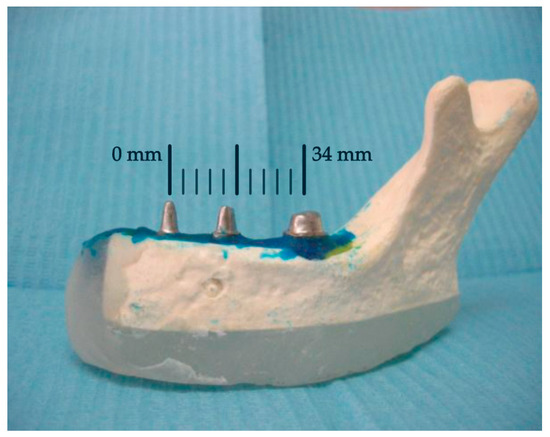
Figure 5.
Teeth included in the hemimandible.
2.2. Statistical Analysis
Kruskal–Wallis [12] test and linear regression were employed for data analysis in the present research. The Kruskal–Wallis test is a non-parametric method employed in statistical analysis to determine whether there are significant differences among multiple independent groups. Linear regression is a fundamental statistical technique used to model the relationship between a dependent variable and one or more independent variables [13]. In essence, it seeks to understand and quantify the linear relationship between variables. All statistical analyses were performed with the statistical software R version 4.2.1 [14].
2.3. Extensometry
To determine the stress/strain phenomena that may occur in the support ground of a bridge with or without a rigid connector under the action of occlusal loads, one of the techniques that can be used is extensometry. As discussed in Section 5, one of its main advantages is that it is a non-destructive technique, so we can use the same sample at different stages, eliminating the variability between the different specimens.
This technique has already been used by various authors [15,16,17,18] in the field of dentistry. However, for the study of rigid and non-rigid connectors in fixed prostheses, the most widely used methods have been finite elements [19,20,21] and photoelasticity [3,5,22], since they make it possible to visualize the distribution of stress inside the model. In any case, none of these three procedures can faithfully represent the complex behavior of organic tissues, and therefore, the results obtained must be treated with caution when making therapeutic decisions.
The measurement of quantities such as torque, load, or pressure by means of strain gauge is based on the modification experienced by the value of the electrical resistance of the gauge when it is deformed as a result of the applied forces. The procedure is as follows: a strain gauge is adhered to the material under study before applying the loads to be measured. Concurrently, with the material under investigation, the gauge undergoes deformation, and this deformation, or strain, alters the gauge electrical resistance. This alteration is then quantified utilizing a Wheatstone bridge, which measures the change in voltage, specifically, the imbalance across the bridge. Ultimately, this variation in voltage, in conjunction with the gauge factor, can be converted into strain.
With this method, the effect of stress on an external force can be analyzed on a structure based on the principle of the change in electrical resistance or physical properties, providing accurate results under a wide variety of test conditions. It is a non-destructive and repetitive analysis with different loads. However, it provides information point-by-point, without a general context, which makes it difficult to understand in complex models under a dynamic effect. It is also difficult to determine if a mistake has been made at any point in the trial.
Although extensometry is a valid method for quantifying deformations, it is no less true that, in dentistry, it is not a frequent procedure in research designs. On the contrary, the most commonly used methods for determining the distribution and concentration of stress have been the finite element analysis method [23] and the photoelasticity technique. The latter is a physical resource that provides paths and images which demonstrate the mechanical behavior of the object piece. It consists of an optical method, with the application of the properties of polarized light, based on the accidental birefringence of transparent isotropic bodies and certain resins. Birefringence is the ability of a transparent material, when subjected to the action of an external force, to separate the polarized light that falls on it into two rays, perpendicular to each other. Of the two rays, each one is out of phase with respect to the other, creating patterns or stripes visible through a polaroscope. With this system, the field of influence of an external force can be determined repetitively without permanent deformation. The transparency of photoelastic materials, such as flexible epoxysulfide and polysulfide resins, allows for the stress concentration in the internal part of the model to be observed directly. These measurements are qualitative and barely quantitative, and the performance of the force is analyzed in a static and non-dynamic way.
2.4. Construction of the Bridges and Placement of the Interlocks
For this study, five different bridge designs were made (Figure 6) and are as follows:
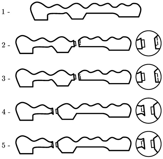
Figure 6.
Study of interlock positions.
- Bridge with rigid connectors between the retainers and the pontics (RIGID).
- Bridge with a non-rigid connector placed on the distal surface of the intermediate abutment and a cervical retention stop (PIDPITC).
- Bridge with a non-rigid connector placed on the distal surface of the intermediate abutment and an occlusal stop (PIDPITO).
- Bridge with a non-rigid connector placed on the mesial surface of the intermediate abutment and a cervical stop (PIMPITC).
- Bridge with a non-rigid connector placed on the mesial surface of the pier abutment and an occlusal stop (PIMPITO).
All non-rigid connectors used have non-adjustable slide attachments, in the form of a solid “Glissier”-type cylinder (Figure 7). All the bridges were constructed by the classic procedure of lost wax casting in a non-noble alloy of cobalt chromium, without nickel or beryllium and with balanced properties for high-quality ceramic metal restorations. The proportions in weight of the alloy are 55.2% Co, 24% Cr, 15% W, 4% Fe, 1% Si, and 0.8% Mn. This is a commercial alloy equivalent to F90 grade.
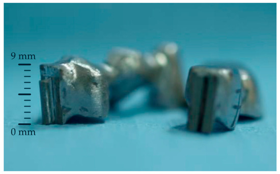
Figure 7.
“Glissier”-type interlock.
In total, 12 bridges of each of the five designs were manufactured, representing a total of 60 bridges (Figure 8).
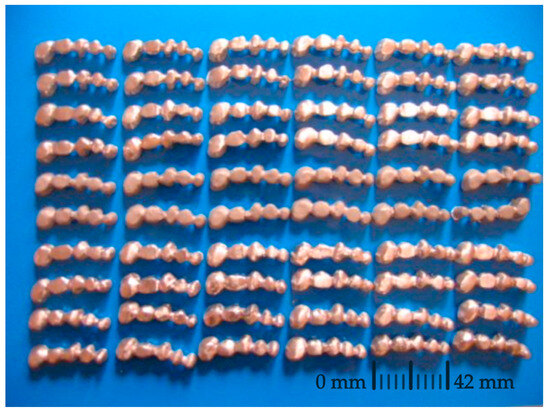
Figure 8.
Bridges used for the study.
2.5. Application of Load and Strain Gauge Measurements
To evaluate the strain and stresses produced on the ground of the support, model EA-06-015RC-12 rosette-type strain gauges (Micro-Measurements division of Vishay Group Precision, Raleigh, NC, USA) were used. This type of gauge consists of a set of three gauges oriented at 0º, 45º, and 90º (Figure 9) to be able to accurately estimate the main tensions and deformations. A total of three rosettes were used, one per abutment tooth (canine, second premolar, and second molar), attached to the hemi-jaw, as shown in Figure 9. In this way, we can evaluate the deformation in the ground of the support of each of them.
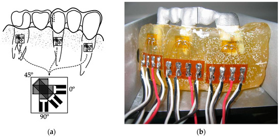
Figure 9.
Layout of the strain gauges attached to the hemi-jaw: (a) schematic drawing of the layout and the rosette-type strain gauge and (b) image depicting the layout.
Finally, the micro-deformations in each of the directions of the gauge were measured with data acquisition equipment of the Vishay brand model P3 (Micro-Measurements division of Vishay Group Precision, Raleigh, NC, USA). This model has four input channels, which allowed us to record the deformations of a complete gauge for each test. The principal strains derived from recorded measurements are computed from the following expression:
The values of the forces applied to the oral cavity can vary depending on various factors: age, sex, the direction of application of the force, the strength of the closing muscles, the region of the oral cavity and facial morphology, among other factors.
The load used to evaluate the deformations suffered by the support ground with the different bridge designs was 100 N because according to various studies [24,25], this is the average force exerted during the masticatory cycle. The point of application of the forces was the central area of the occlusal surface in each of the 5 dental units that make up the bridge with an axial direction, following the same direction as the major axis of the tooth (Figure 10).
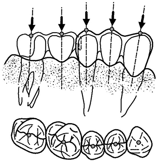
Figure 10.
Point of application of the forces following major axis of the tooth.
The load was applied by means of an electromechanical machine with central actuator model EM1/5/FR/5CM (Microtest S. A., Madrid, Spain), see Figure 11. The device has a load cell of 5 kN to measure the force exerted in each test. The loading process, in each of the positions, consisted of a preload at a speed of 1 N/s up to a value of 1.5 N, and a loading process at a speed of 20 N/s until reaching 100 N.
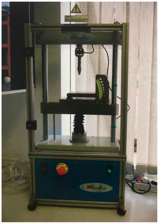
Figure 11.
Testing machine.
To prevent the work model from moving when applying the load, a metal part was designed to fix the prosthesis to the base of the actuator (Figure 12).
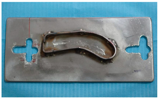
Figure 12.
Testing machine holder for the tested model.
Altogether, five loading points (canine, mesial pontics, intermediate abutment, distal, and molar pontics) and five types of prostheses (one rigid and four with interlock in occlusal mesial, cervical mesial, occlusal distal and cervical distal) were used. This provides us with a total of 25 configurations or type tests. In each of the tests, the measurement in the field of the support of each of the three abutments was performed, which provides us a total of 75 measurements or records for each complete round of tests.
Finally, for a good statistical sample, each test was repeated 12 times, so we obtained 900 measurements or records, 300 in each support. Such number of repetitions allows the detection of small effect size differences [26], when the Kruskal–Wallis test is performed making use of either a variable of 3 levels (f = 0.1154) or 5 levels (f = 0.1036).
3. Results
Table 1 shows the average principal strain and standard deviation values by bridge model. Results obtained by means of the Kruskal–Wallis test [12] and applied to these data allow us to infer that there are statistically significant differences in the value of the strain among groups with a statistic value of and four degrees of freedom (, which means a p-value lower than 0.01 that allows us to reject the null hypothesis with non-statistical significant differences and with an error lower than 1%. The model with the highest average value of maximum principal strain was PIDPITO, followed by PIMPITC. This can be seen in Figure 13, where a boxplot of strains by bridge models is presented.

Table 1.
Principal strains obtained by bridge model in .
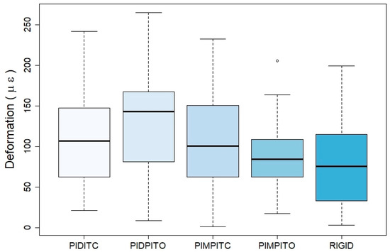
Figure 13.
Boxplot of principal strains by bridge models.
When models are compared taking into account the point where the force is applied (Table 2), statistically significant differences are found using the Kruskal–Wallis test, with a statistic of and four degrees of freedom, meaning that the probability of an error in the detection of statistically significant differences would be lower than 1%. The highest values are found for the canine, followed by the pier abutment. These results are graphically presented in Figure 14.
Table 2.
Principal strains obtained considering the force application point in .
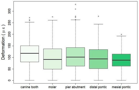
Figure 14.
Boxplot of strains by force application point.
When the position of the strain gauges in the different models is considered (Table 3), it is found that there are also statistically significant differences among them with a statistic value of , two degrees of freedom, and an error lower than 1% in the differences detected. Maximum values are obtained at the pier abutment. Please see the graphical results presented in the boxplot of Figure 15.
Table 3.
Principal strains obtained considering strain gauges position in .
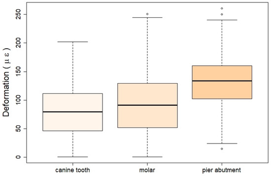
Figure 15.
Boxplot of strains by strain gauges position.
Finally, a linear regression model of the strain was calculated using as independent variables all those considered in the study (kind of bridge, point where the force is applied, and strain gauge considered; see Table 4). As reference categories, those with the lowest strain values in the univariate analysis were taken into account. These are as follows: for the type of bridge, rigid; for the point of force application, mesial pontic; and for the strain gauge, the canine position. The results obtained show how almost all the categories in all the variables are significant, except for the molar in point of force application and molar again for strain gauge. This model has a value of 36.46% with an adjusted of 35.74%. The model can be interpreted as that the higher the coefficient value, the higher the expected strain. This means that the highest strain values will be obtained for a bridge of type PIDPITO, when the force is applied at the canine tooth, and the value is recorded by the strain gauge located at the pier abutment.
Table 4.
Linear regression model of strain considering the variables’ bridge type, force application, and strain gauge.
4. Discussion
The results show that after the application of an axial force of 100 N in isolation, the greatest strain is recorded in the gauge placed in the intermediate abutment (second premolar) and with values much higher than those recorded in the canine or in the second molar. This result is regardless of the point of application of the force and the design of the bridge. Regarding the latter, the mechanical effects, in terms of strain, are more noticeable in interlock bridges than in rigid ones, notwithstanding the place of registration. This fact is more evident when it comes to the gauge located on the pier abutment. Therefore, in rigid and non-rigid bridge designs, the greatest strain is recorded in the intermediate abutment, and this strain is higher in the interlocked bridges than in the rigid design. In the case of non-rigid designs, the bridge that has the interlock on the distal surface of the pier abutment and the occlusal retention stop is where the greatest strain is recorded. On the other hand, the bridge that has the interlock on the mesial surface of the intermediate abutment and the stop in occlusal shows the least strain.
If we relate the reading place of the strain and the type of bridge, we observe that, of the three situations, the design of the rigid bridge is the one that suffers the least deformation. Conversely, if we only consider the strain reading point for the four interlock bridge designs, we observe that the greatest strain is recorded in the gauge placed in the intermediate abutment, with values higher than those recorded in the molar gauge and in the canine.
The same occurs with bridges with a rigid design and in a more remarkable way, in that strain recorded in the intermediate abutment is much higher than that registered in the canine. This suggests that the presence of an intermediate abutment in a fixed prosthetic restoration, with or without interlock, influences the maximum tension supported by the abutments, especially in relation to the intermediate abutment. On the contrary, Laundry [5] suggests that stress could break or detach any terminal retainer but not the intermediate abutment, so that the loads centered on the intermediate abutment are partly supported by the terminal abutments. In this case, a stress breaker would not be necessary, or at least not in the pier abutment.
The reason why the intermediate abutment supports the greatest deformation is that since it is a five-unit bridge, it is always the abutment that is isolated, with edentulous spaces on both sides with a tendency to act as a fulcrum. In addition, it should be taken into account that this type of bridge is a restoration that combines curved and straight sections and that it is the area where considerable overexertion is generated, due to the great length of the sections through which movements, magnitudes, and directions are transmitted regardless of mobility other than 108 abutments. Shillinburg and Fisher [4] and Shillinburg et al. [1] define the use of an interlock on the distal surface of the intermediate abutment and the cervical retention stop when making a five-unit bridge with intermediate abutment because they maintain that with its use, and they resolve the differences between the magnitudes and the divergent directions of the movement, the fulcrum function of this and the difference of retention between the terminal abutments. In their opinion, this avoids or prevents the failure of the weakest retainer, usually the canine. The position of the interlock is also defended by Akulwar [27], who affirms that the use of a non-rigid connector increases the life of the restoration while minimizing stress on the abutments. This makes physiological movement of the teeth possible, unlike rigid connectors, and they maintain that an adequate selection of the stress breaker is important in the treatment plan of the intermediate abutment.
On the other hand, Gill’s old article [28] argues that the non-rigid connector must be placed on one or both proximal surfaces of the pier abutment to avoid fulcrum. Adams [29], for the same purpose, advised the use of a non-rigid connector on the distal surface of the intermediate abutment and a second, if desired, on the distal surface of the anterior abutment. In the study of the analysis of the effects of stress of non-rigid connectors in fixed prosthesis with pier abutment, Oruc et al. [21] believe that in this type of prosthetic restorations, high stress concentrations occur around said intermediate abutment, with a displacement in the terminal abutments damaging the abutment teeth. Therefore, they argue that non-rigid connectors can be used to eliminate the fulcrum effect of the intermediate abutment. They also indicate that the ideal placement of the non-rigid connector is on the distal surface of the intermediate abutment, making no reference to the location of the stop. On the contrary, Ziada et al. [30] consider that this design of a bridge with an intermediate abutment should be avoided, given the increased risk of decreasing the retainer of said abutment.
On the other hand, Misch [31] analyzes the tooth–implant junction in clinical situations with the presence of an intermediate abutment. They define that this intermediate abutment can be a natural tooth or an implant, and each type plays a different role in the overall treatment. When an implant serves as an intermediate abutment between two natural teeth, the difference in movement between the implant and the tooth can lead to more complications than the attachment of a tooth to two implants. The intermediate implant shows less movement than a terminal abutment and acts as a fulcrum of a class I lever. This problem is amplified by a longer lever arm when there is a pontic between the implant and the tooth. When the implant acts as a fulcrum, a common consequence is that an abutment is loosened (usually the least mobile or the least retentive crown), and tooth decay appears. Therefore, this type of prosthesis should be avoided, especially with the use of rigid connectors. If another therapeutic option is not possible, a non-rigid connector can be used, where its ideal position would be between the implant and the less retentive crown, to prevent the implant from acting as a fulcrum.
They also argue that in conventional fixed prostheses, the male part of the interlock is placed on the mesial surface of the pontic and the female part on the distal surface of the pier abutment, thus preventing the mesial movement from detaching the retainer. However, the implant does not experience an inclination towards mesial and the location of the stress breaker is more flexible.
On the contrary, if a natural tooth serves as an intermediate abutment between two implants, these authors state that the situation is completely different. When two or more implants support only the prosthesis load, the natural tooth becomes a vital pontic, so the use of non-rigid connectors is not appropriate here; a completely rigid prosthetic design would be preferable.
However, the tendency of the pier abutment to act as a fulcrum is not a general criterion. Standlee and Caputo [32] conclude that there is no evidence that the intermediate abutment acts as a fulcrum. Indeed, their study showed that when a non-rigid connector was incorporated into the bridge, the stress increased on the abutments where the force was applied, while the stress on the abutments on the opposite side of the force application decreased. In our study, it can be observed that a greater strain occurs when it is registered in the gauge placed in the same tooth on which the force is applied (when the gauge and point of application of the force coincide) or in the adjacent teeth. It is also observed that the deformation reduces as the point of application of the force of the reading gauge is moved away.
For the construction of the hemimandible, the Vishay PL-2 resin was used. This resin has mechanical properties similar to those of bone. This material has already been successfully used by other authors [3,33] in photoelasticity studies. As for the construction of the abutment teeth, a metallic replica of the teeth was chosen to avoid fractures that occur in models with natural teeth. In the present study, the presence of the periodontal ligament was not simulated. However, the attempts of some authors [3,5] to model the behavior of the ligament show a great disparity, so we preferred not to introduce additional material into the support construction.
Another point of controversy is the manufacturing material of dental bridges and whether or not to coat them with ceramic materials. In this investigation, a non-noble chromium–cobalt alloy without nickel or beryllium was used. Other authors have used type III gold [5,19], chrome-nickel [21], silver–palladium [3], and other non-noble alloys [20]. Therefore, it is appreciated that there is no unanimity when it comes to choosing a specific type of alloy. In relation to the structure of the bridge, the shape and size of the connectors are important factors, as has been pointed out by various authors [19,20,34,35].
Additionally, as it has been previously demonstrated with other prosthodontic or restorative materials, some variables can have a significant influence on the long-term mechanical behavior of dental frameworks. Therefore, future reports evaluating the effects of wear [36] and acidic environment [37] should also be assessed for stress breaker bridges with pier abutment.
In relation to the application of the forces, to evaluate the deformations in the medium ground of the support, a value of 100 N was used in this study. This load is the average force exerted during chewing, according to various authors [24,25].
To quantify the deformation produced in the support ground, extensometric analysis was performed by the use of strain gauges. One of its main advantages is that it is a non-destructive technique. In this way, we can use the same sample at different stages, eliminating the variability factor between the different specimens. This technique has already been used by various authors [15,16,17,18] in the field of dentistry. However, for the study of rigid and non-rigid connectors in fixed prostheses, the most widely used methods have been finite elements [19,20,21] and photoelasticity [3,5,22,33], since they make it possible to visualize the distribution of stress inside the model.
Finally, due to the inherent limitations of the study, the results obtained must be approached with prudence when making therapeutic decisions. Firstly, the models are constructed with plastic and metallic materials that cannot precisely replicate organic tissues complex behavior. Furthermore, the tests have been conducted under static conditions, but the force of chewing is cyclical; therefore, phenomena such as fatigue may be relevant. Lastly, all statistical methods have specific limitations. In regression models, overfitting can be an issue depending on the characteristics of the samples being worked with and, therefore, may generate errors when applied to future independent samples [38].
5. Conclusions
According to the obtained results, and within the limitations of this method, the key conclusions that can be drawn are as follows:
- Five bridge designs, one with rigid connectors and four with non-rigid connectors, of a five-unit prosthetic restoration bridge were analyzed by means of extensometry. A total of 60 bridges, 12 of each type, were manufactured and tested, and thus 900 measurements were recorded.
- Mechanical effects, in terms of strain, are more noticeable in interlock bridges than in rigid ones, regardless of the place of registration.
- In the case of non-rigid designs, the bridge with the interlock on the distal surface of the pier abutment and the occlusal retention stop (PIDPITO) is where the highest average value of maximum strain is recorded. Conversely, the bridge model with interlock in the mesial surface and the stop by occlusal (PIMPITO) is the one that shows the least deformation.
- The presence of an intermediate abutment in a fixed prosthetic restoration, with or without interlock, influences the maximum tension supported by the abutment, especially in relation to the intermediate abutment. This result is independent of the point of application of the load unusually long or complex.
Author Contributions
Conceptualization, C.B.d.C.; Data curation, C.B.d.C.; Formal analysis: G.F.V., F.S.L. and J.G.R.; Investigation: C.B.d.C.; Methodology: F.S.L. and J.G.R.; Resources, C.B.d.C.; Validation: G.F.V.; Visualization: J.G.R.; Writing—original draft: J.G.R.; Writing—review and editing: G.F.V., F.S.L. and J.G.R. All authors have read and agreed to the published version of the manuscript.
Funding
This research received no external funding.
Institutional Review Board Statement
Not applicable.
Informed Consent Statement
Not applicable.
Data Availability Statement
The data presented in this study are available on request from the corresponding author.
Conflicts of Interest
The authors declare no conflict of interest.
References
- Shillingburg, H.; Hobo, S.; Whitsett, L. Fundamentos de Protesis Fijas, 3rd ed.; Quintessenz: Barcelona, Spain, 1990. [Google Scholar]
- Kuruvila, A.; Joseph, S.; Jayalekshmi, N.; Menon, S. The key to the management of pier abutment: An alternative approach. J. Int. Oral Health 2017, 9, 136. [Google Scholar] [CrossRef]
- Moulding, M.B.; Holland, G.A.; Sulik, W.D. Photoelastic stress analysis of supporting alveolar bone as modified by nonrigid connectors. J. Prosthet. Dent. 1988, 59, 263–274. [Google Scholar] [CrossRef] [PubMed]
- Shillingburg, H.T.; Fisher, D.W. Nonrigid Connectors for Fixed Partial Dentures. J. Am. Dent. Assoc. 1973, 87, 1195–1199. [Google Scholar] [CrossRef] [PubMed]
- Landry, K.E.; Johnson, P.F.; Parks, V.J.; Pelleu, G.B. A photoelastic study to determine the location of the nonrigid connector in a five-unit intermediate abutment prosthesis. J. Prosthet. Dent. 1987, 57, 454–457. [Google Scholar] [CrossRef] [PubMed]
- Moulding, M.B.; Holland, G.A.; Sulik, W.D. An alternative orientation of nonrigid connectors in fixed partial dentures. J. Prosthet. Dent. 1992, 68, 236–238. [Google Scholar] [CrossRef] [PubMed]
- Schlumberger, T.L.; Bowley, J.F.; Maze, G.I. Intrusion phenomenon in combination tooth-implant restorations: A review of the literature. J. Prosthet. Dent. 1998, 80, 199–203. [Google Scholar] [CrossRef] [PubMed]
- Huang, Y.-C.; Ding, S.-J.; Yuan, C.; Yan, M. Biomechanical analysis of rigid and non-rigid connection with implant abutment designs for tooth-implant supported prosthesis: A finite element analysis. J. Dent. Sci. 2022, 17, 490–499. [Google Scholar] [CrossRef] [PubMed]
- Márquez Córdoba, C.; Escobar Restrepo, J.C.; Latorre Correa, F.; Villarraga Ossa, J. Stress distribution on a five unit fixed partial prosthesis with intermediate abutment: Biomechanical analysis using a finite element model. Rev. Fac. Odontol. Univ. Antioq. 2011, 22, 153–163. [Google Scholar]
- Hernández, G.; Ferrús, J.; Bascones, A.; Hernández, G.; Ferrús, J.; Bascones, A. Ferulizaciones diente-implante. Av. Periodoncia Implantol. Oral. 2005, 17, 165–174. [Google Scholar] [CrossRef][Green Version]
- Cañada Madinazcoitia, L.; Del Río Highsmith, J.; Martínez Vázquez de Parga, J. Tratamiento de pacientes parcialmente edéntulos con prótesis dentoimplantosoportadas. Av. Periodoncia Implantol. Oral. 2001, 13, 9–17. [Google Scholar] [CrossRef]
- Kruskal, W.H.; Wallis, W.A. Use of Ranks in One-Criterion Variance Analysis. J. Am. Stat. Assoc. 1952, 47, 583–621. [Google Scholar] [CrossRef]
- Freedman, D. Statistical Models: Theory and Practice; Paperback; Cambridge University Press: Cambridge, UK, 2009. [Google Scholar]
- R Core Team. R: A Language and Environment for Statistical Computing; R Core Team: Vienna, Austria, 2021. [Google Scholar]
- Ferrario, V.F.; Sforza, C.; Zanotti, G.; Tartaglia, G.M. Maximal bite forces in healthy young adults as predicted by surface electromyography. J. Dent. 2004, 32, 451–457. [Google Scholar] [CrossRef] [PubMed]
- Ferrario, V.F.; Sforza, C.; Serrao, G.; Dellavia, C.; Tartaglia, G.M. Single tooth bite forces in healthy young adults. J. Oral Rehabil. 2004, 31, 18–22. [Google Scholar] [CrossRef]
- Al-Ghannam, N.A.; Fahmi, F.M. Effect of direct relining on stresses at the denture base and the metal frame of removable partial dentures. J. Contemp. Dent. Pr. Pract. 2005, 6, 37–47. [Google Scholar] [CrossRef]
- Prombonas, A.E.; Vlissidis, D.S. Comparison of the midline stress fields in maxillary and mandibular complete dentures: A pilot study. J. Prosthet. Dent. 2006, 95, 63–70. [Google Scholar] [CrossRef] [PubMed]
- Savion, I.; Saucier, C.L.; Rues, S.; Sadan, A.; Blatz, M. The pier abutment: A review of the literature and a suggested mathematical model. Quintessence Int. 2006, 37, 345–352. [Google Scholar] [PubMed]
- Harshitha Gowda, B.H.; Satish Babu, C.L. Connector design in a long-span-fixed dental prosthesis: A three-dimensional finite element analysis. Indian J. Dent. Res. 2013, 24, 178–182. [Google Scholar] [CrossRef] [PubMed]
- Oruc, S.; Eraslan, O.; Tukay, H.A.; Atay, A. Stress analysis of effects of nonrigid connectors on fixed partial dentures with pier abutments. J. Prosthet. Dent. 2008, 99, 185–192. [Google Scholar] [CrossRef]
- Sadowsky, S.J.; Caputo, A.A. Effect of anchorage systems and extension base contact on load transfer with mandibular implant-retained overdentures. J. Prosthet. Dent. 2000, 84, 327–334. [Google Scholar] [CrossRef]
- Sánchez Lasheras, F.; Gracia Rodríguez, J.; Mauvezín-Quevedo, M.; Martín-Fernández, E.; Bobes-Bascarán, J.; Llanos-Lanchares, H.; Álvarez-Arenal, Á. Does the transversal screw design increase the risk of mechanical complications in dental implants? A finite elements analysis. Int. J. Numer. Method Biomed. Eng. 2019, 35, e3205. [Google Scholar] [CrossRef]
- Bosman, F. Between biting and swallowing. Physiology of Mastication. Ned. Tijdschr. Tandheelkd. 1995, 102, 438–440. [Google Scholar]
- Lundren, D.; Laurell, L. Occlusal force pattern during chewing and biting in dentitions restored with fixed bridges of cross-arch extension. J. Oral Rehabil. 1986, 13, 57–71. [Google Scholar] [CrossRef]
- Cohen, J. Statistical Power Analysis for the Behavioral Sciences; Hardcover; L. Erlbaum Associates: Mahwah, NJ, USA, 1988. [Google Scholar]
- Ravikumar, A. Non-Rigid Connector for Managing Pier Abutment in FPD: A Case Report. J. Clin. Diagn. Res. 2014, 8, ZD12. [Google Scholar] [CrossRef]
- Gill, J.R. Treatment planning for mouth rehabilitation. J. Prosthet. Dent. 1952, 2, 230–245. [Google Scholar] [CrossRef]
- Adams, J.D. Planning posterior bridges. J. Am. Dent. Assoc. 1956, 53, 647–654. [Google Scholar] [CrossRef] [PubMed]
- Ziada, H.M.; Orr, J.F.; Benington, I.C. Photoelastic stress analysis in a pier retainer of an anterior resin-bonded fixed partial denture. J. Prosthet. Dent. 1998, 80, 661–665. [Google Scholar] [CrossRef] [PubMed]
- Misch, C.E. Prótesis Dental Sobre Implantes, 2nd ed.; Elsevier: Amsterdam, The Netherlands, 2015. [Google Scholar]
- Standlee, J.P.; Caputo, A.A. Load transfer by fixed partial dentures with three abutments. Quintessence Int. 1988, 19, 403–410. [Google Scholar] [PubMed]
- Sutherland, J.K.; Holland, G.A.; Sluder, T.B.; White, J.T. A photoelastic analysis of the stress distribution in bone supporting fixed partial dentures of rigid and nonrigid design. J. Prosthet. Dent. 1980, 44, 616–623. [Google Scholar] [CrossRef] [PubMed]
- Motta, A.B.; Pereira, L.C.; da Cunha, A.R.C.C.; Duda, F.P. The influence of the loading mode on the stress distribution on the connector region of metal-ceramic and all-ceramic fixed partial denture. Artif. Organs 2008, 32, 283–291. [Google Scholar] [CrossRef] [PubMed]
- Omar, R.; Abduljabbar, T.; Al-Ali, K.; Smyth, M.; El-Agouri, R. Dimensions of metal framework components of metal-ceramic fixed partial dentures constructed in a dental school setting. Quintessence Int. 2004, 35, 820–825. [Google Scholar]
- Gwon, B.; Bae, E.-B.; Lee, J.-J.; Cho, W.-T.; Bae, H.-Y.; Choi, J.-W.; Huh, J.B. Wear Characteristics of Dental Ceramic CAD/CAM Materials Opposing Various Dental Composite Resins. Materials 2019, 12, 1839. [Google Scholar] [CrossRef] [PubMed]
- Colombo, M.; Gallo, S.; Poggio, C.; Ricaldone, V.; Arciola, C.R.; Scribante, A. New Resin-Based Bulk-Fill Composites: In vitro Evaluation of Micro-Hardness and Depth of Cure as Infection Risk Indexes. Materials 2020, 13, 1308. [Google Scholar] [CrossRef] [PubMed]
- Babyak, M.A. What You See May Not Be What You Get: A Brief, Nontechnical Introduction to Overfitting in Regression-Type Models. Psychosom. Med. 2004, 66, 411–421. [Google Scholar] [CrossRef] [PubMed]


Disclaimer/Publisher’s Note: The statements, opinions and data contained in all publications are solely those of the individual author(s) and contributor(s) and not of MDPI and/or the editor(s). MDPI and/or the editor(s) disclaim responsibility for any injury to people or property resulting from any ideas, methods, instructions or products referred to in the content. |
© 2024 by the authors. Licensee MDPI, Basel, Switzerland. This article is an open access article distributed under the terms and conditions of the Creative Commons Attribution (CC BY) license (https://creativecommons.org/licenses/by/4.0/).