Article

Exploring Stresses in Mandibular Jawbone during Implant Insertion: A Three-Dimensional Explicit Dynamic Analysis

1
Department of Aeronautical and Automobile Engineering, Manipal Institute of Technology, Manipal, Manipal Academy of Higher Education, Manipal 576104, Karnataka, India
2
Department of Conservative Dentistry and Endodontics, Manipal College of Dental Sciences, Manipal, Manipal Academy of Higher Education, Manipal 576104, Karnataka, India
3
Department of Oral and Maxillofacial Pathology and Oral Microbiology, Manipal College of Dental Sciences, Manipal, Manipal Academy of Higher Education, Manipal 576104, Karnataka, India
4
Department of Mechanical Engineering, Hirasugar Institute of Technology, Nidasoshi, Belagavi 591236, Karnataka, India
*
Author to whom correspondence should be addressed.
Prosthesis 2024, 6(2), 301-314; https://doi.org/10.3390/prosthesis6020023
Submission received: 31 January 2024 / Revised: 27 February 2024 / Accepted: 28 February 2024 / Published: 25 March 2024
(This article belongs to the Collection Oral Implantology: Current Aspects and Future Perspectives)

Abstract

:
In dental implant insertion, an artificial foundation is prepared for the prosthetic device, which involves the surgical positioning of the implant in the jaw bone. The success of dental implants relies on the osseointegration process. The biomechanical factors, such as stress and strain, developed during the insertion affect the jawbone and its surroundings. In this current study, the stresses during the implant insertion in the mandibular jawbone bone are analyzed using three-dimensional explicit dynamic analysis, and the Cowper–Symonds model is implemented with the damage model. The implant’s design has a substantial impact on stress distribution within the cancellous bone during the insertion procedure. The stress variation takes place as the implant moves into the pre-drilled hole. This is because of the contact between the bone and the fixture on the implant. The upper edge of the predrilled site shows that the stresses are more at the crestal region of the implant due to surface area. There is a gradual increase in the stress level as the implant reaches the lower edge from the top edge. This is because of the concept of mechanical interlocking. Clinicians can use this information to anticipate and address potential stress-related challenges during implant placement.

1. Introduction

In dentistry, osseointegration commonly refers to the integration of dental implants with the jawbone [1]. The success of dental implants relies on the osseointegration process, where the bone cells in the jaw grow and adhere to the surface of the implant, creating a stable and durable foundation for the artificial tooth [2]. The success of osseointegration depends on various factors, including the material composition of the implant, the surgical technique used, and the overall health of the patient. The stability due to the osseointegration of the implant plays a significant role in the bone regeneration around the implant. Stability prevents micro-movements of the implant within the bone. Even small movements can lead to irritation, inflammation, and, eventually, failure of the implant [3]. Osseointegration ensures that the implant is securely anchored, minimizing the risk of such movements. The stability achieved through osseointegration not only ensures the success of the implant but also contributes to the overall health and longevity of the surrounding bone and tissues. This concept is applicable not only in dentistry but also in orthopedic and other medical implant applications where integration with the natural bone is essential [4]. Implant success is influenced by the bone type and bone quality at the implant site. Type I or II bone provides better stability compared to Type III or IV bone [5,6]. An implant with a roughed surface or bioactive coating is recommended for better integration [7].
In dental implant insertion, an artificial foundation is prepared for the prosthetic device, which involves surgical positioning of the implant in the jaw bone [8,9]. During the implant insertion, the patient’s medical and dental history is checked. The quality and quantity of available bone are assessed through diagnostic tools such as X-rays and CT scans [10,11]. The appropriate type, size, and positioning of the implant are decided based on the treatment planning [12]. Local anesthesia is typically administered to numb the area where the implant will be placed. An incision is made in the gum tissue to expose the underlying bone. In some cases, a surgical flap is created to provide better visibility and access to the implant site [13]. Using precise dental drills, a socket is created in the jawbone to accommodate the implant [14]. The implant is inserted into the prepared site by checking the depth and alignment. During the insertion of the implant into the socket, a recommended torque of 40 Newton centimeters is maintained [15]. The biomechanical factors, such as stress and strain, developed during the insertion affect the jawbone and its surroundings. The shape, length, and diameter of the implant play roles in determining the load-bearing capacity and resistance to deformation during insertion. The successful insertion of the implant also depends on the transfer of the stresses generated during the implant insertion [16,17].
Wolff [18] describes the relationship between mechanical stress and bone adaptation. They emphasize the importance of considering biomechanical factors, such as load distribution and stress patterns, to advance optimal bone adaptation and long-term success in the integration of implants. The biomechanical factors and the stresses in the jawbone can cause crestal bone loss. This bone loss in the neck area, particularly in the region just below the implant–abutment interface, leads to the failure of the implant.
Finite element analysis is a numerical stress analysis technique that has proven to be a useful tool in investigating the effect of the biomechanical properties of prostheses on dental implants and also medical implants [19,20,21,22]. Several in vitro studies and finite element analyses were conducted to explore stress transmission at both the implant and peri-implant levels, employing various restorative materials for implant-supported prostheses [23]. In this current study, the stresses during the implant insertion in the mandibular jawbone bone are analyzed using three-dimensional explicit dynamic analysis. The cancellous bone is modeled as elastoplastic, and the Cowper–Symonds model is implemented with the damage model. To analyze the stresses in a jawbone, the implant is modeled as a rigid body.

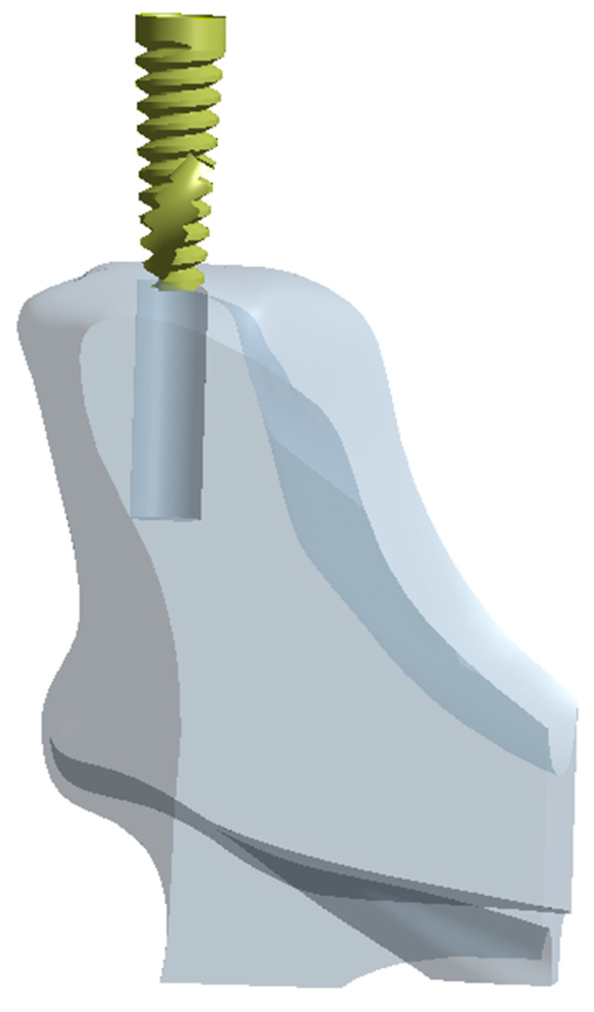
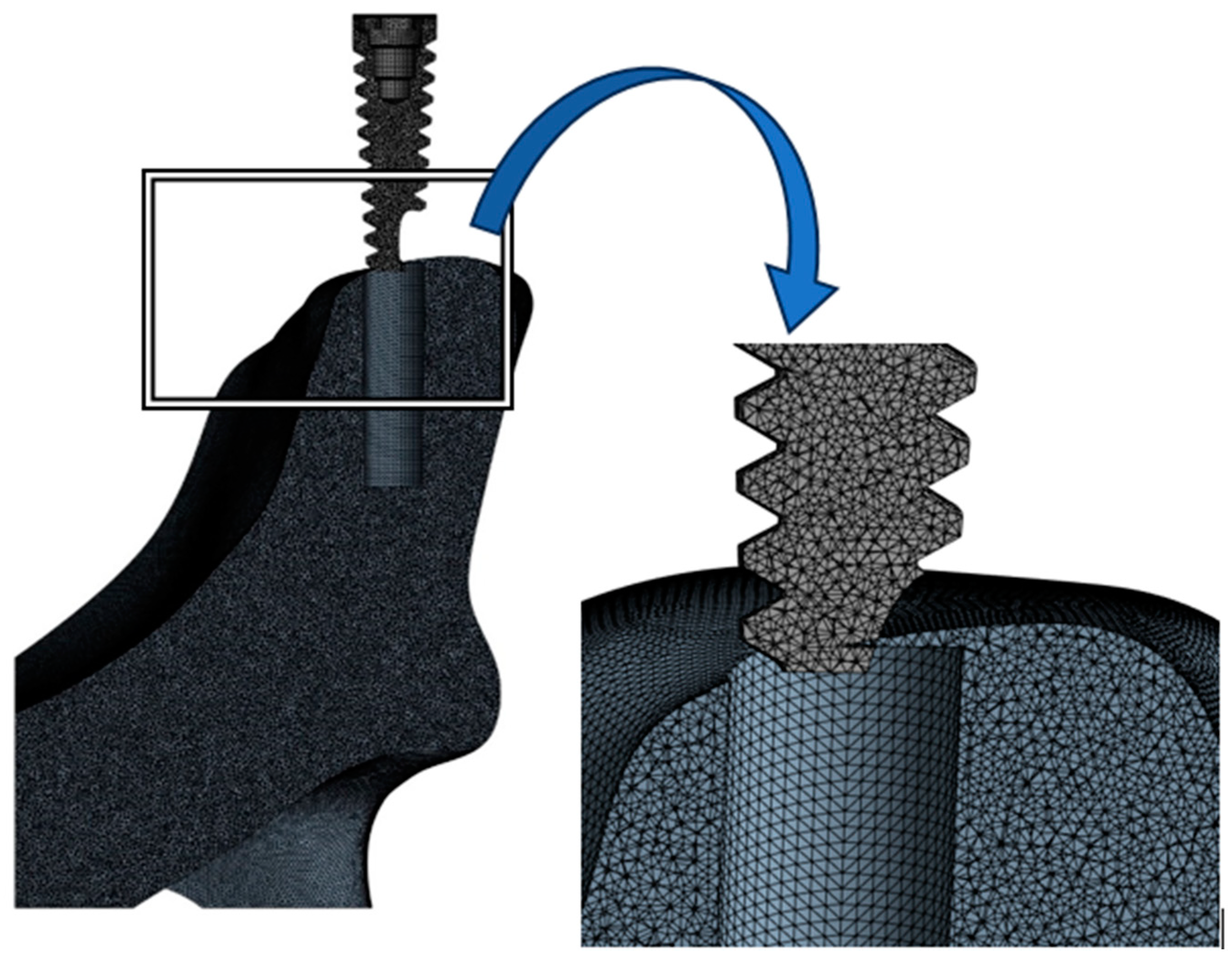
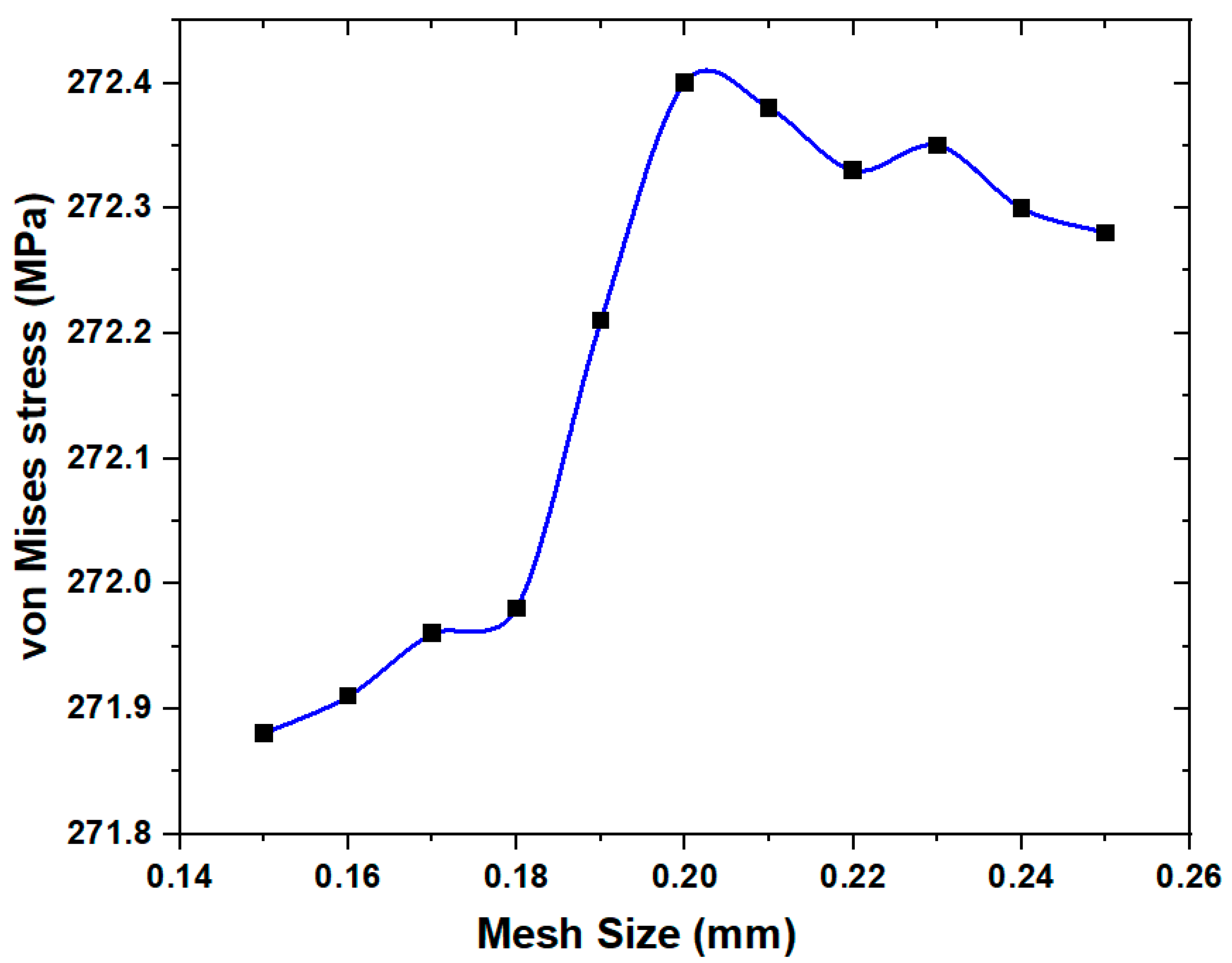
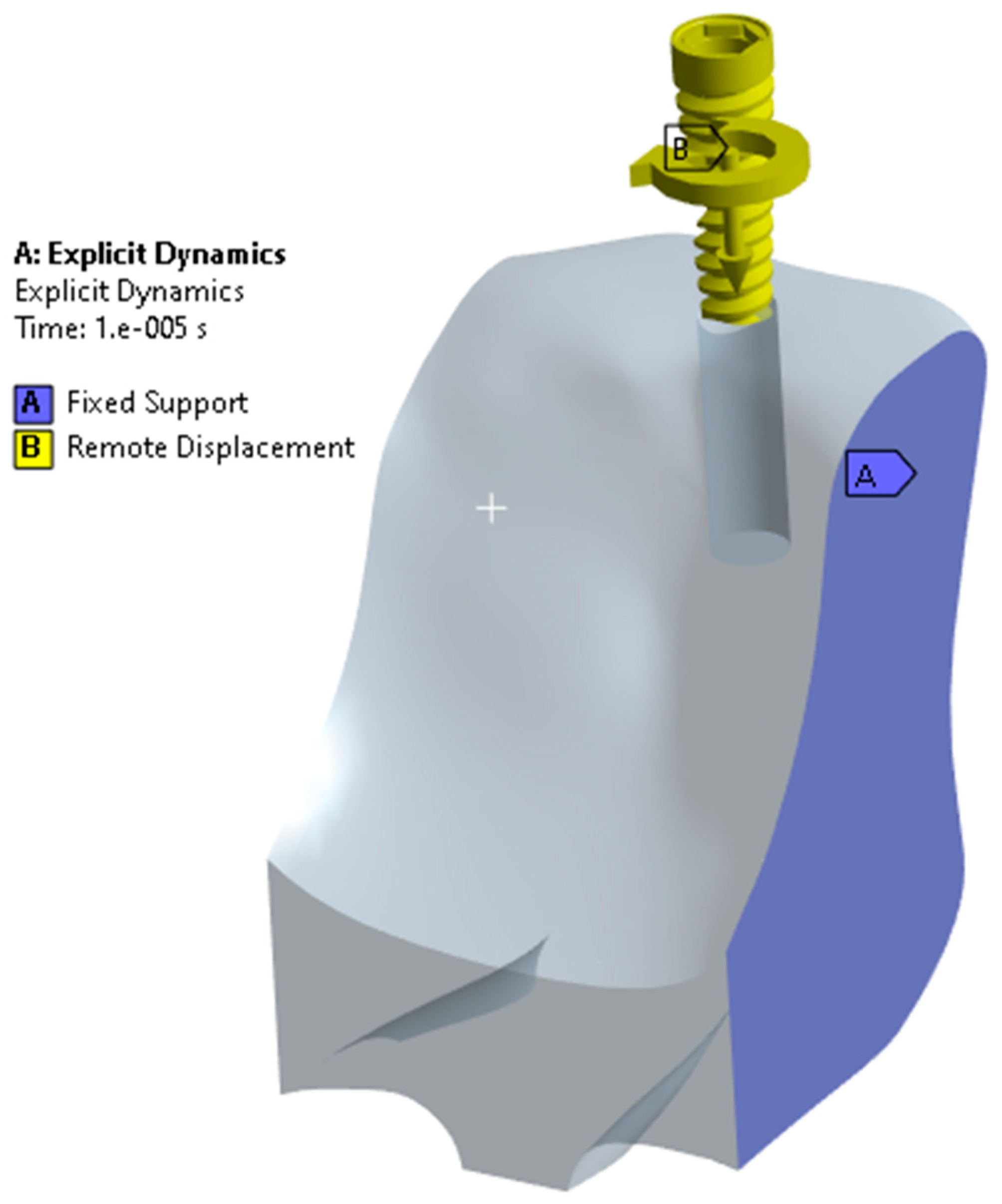
2. Materials and Methods

In the dental implant insertion procedure, an incision is made in the gum tissue to expose the underlying bone. A CT scan of the maxilla and the mandible is adopted for the 3D modeling of mandibular bone. An image-processing open-source software, 3D SLICER, is used to convert the dicom to an editable model. This editable model is transferred to CATIA-3D EXPERIENCE for further editing. An implant measuring 3.75 mm in diameter and 11.5 mm in length [ALPHA BIO], a tapered [24] implant, was modeled using CATIA-3D EXPERIENCE, as shown in Figure 1.
Using Ansys Workbench R2 2023, the model was meshed using 4-node tetrahedral elements. The meshed models are shown in Figure 2.
Figure 3 describes a grid independence study conducted during the simulation of implant insertion. A grid independence study involves varying the mesh size to assess its impact on the simulation results. The goal is to determine the minimum computational requirements necessary to obtain reliable and accurate results. The mesh size was systematically varied between 0.15 mm and 0.25 mm during the implant insertion simulation. This range of mesh sizes was chosen to evaluate the discretization of the model influences the computed stresses. The maximum von Mises stress at the jawbone was considered as the criterion for assessing grid independence. Through multiple iterations, it was determined that a mesh size of 0.2 mm consistently produced reliable results. This mesh size strikes a balance between computational cost and the level of detail required for an accurate simulation. Implementing the 0.2 mm mesh size resulted in the generation of nodes and elements for the model. Figure 2 represents the mesh, showcasing the discretization of the implant and jawbone models. Table 1 provides specific details on the number of elements and nodes generated for both the implant and jawbone models when using a mesh size of 0.2 mm.
The implant is assumed to be rigid, and the cancellous bone is simulated as elastoplastic. The Cowper–Symonds model is implemented with the damage model to analyze the stresses in a jawbone [25]. The Cowper–Symonds model is a temperature-independent plastic kinematics material model, and the associative flow rule was used for the matrix. The strain rate was accounted for using the Cowper–Symonds model, which scaled the yield stress by a strain rate-dependent factor. The model generally works with the failure criterion, such as the strain failure condition. As the tool that moves into the materials reaches the failure state, the corresponding nodes and elements will be deleted from the main base body. The same has been added and highlighted in the revised manuscript [26,27].
When selecting a material model for a cancellous bone model, especially when considering strain-rate dependency and the plastic curve of materials, it is important to choose a model that accurately represents the behavior of the material under varying loading conditions. The choice of a material model depends on the specific characteristics of the material and the loading conditions expected in the application. Experimental data and material testing can provide valuable input for calibrating material models and ensuring their accuracy in representing the material’s behavior under various conditions. The Cowper–Symonds model, Johnson–Cook model, power-law creep model, and viscoplasticity models are the most common models considered for the materials that depend on the strain rate effects [28]. Since the Cowper–Symonds model is simple when compared to other models [29] concerning material failure and has often been applied to the bone material models, we adopted the Cowper–Symonds model for the current analysis.
In finite element methods, according to the ANSYS help manual [30], the equation to calculate the yield stress is given by the Cowper–Symonds model (Equation (1)).
σ y = 1 + ε ˙ C 1 / p σ 0 + β E p ε p e f f
E p = E t a n E E E t a n
where σ 0 is the initial yield stress in MPa, ε ˙ is the strain rate in s−1, and β is the hardening parameter (for the kinematic hardening = 0 and isotropic hardening = 1). C and P are the Cowper–Symonds parameters. ε e f f is the effective plastic strain and E p is the plastic hardening modulus, which depends on the Youngs modulus ( E ) and the tangent modulus ( E t a n ) , as shown in the Equation (2). Table 2 represents the material properties and the Cowper–Symonds model parameters.
For the contact, automatic frictionless contact between the cancellous bone and the implant is adopted. Finite element simulations with material failure, or erosion and eroding contact methods, become relevant. In the Ansys workbench explicit analysis, a small simulation time is used with the erosion property.
For the analysis, the outer surface of the cancellous bone is made to be fixed in all directions. The remote displacement boundary conditions are applied to the implant. This is because we assumed that the implant was a rigid structure. For the implant, a displacement of 10 mm and an angle of 360 degrees was applied. The applied boundary conditions are shown in Figure 4.

3. Results

The von Mises stresses were evaluated on the jawbone bones during implant placement. The stress evaluation provides the biomechanical factors encountered during the implant insertion.

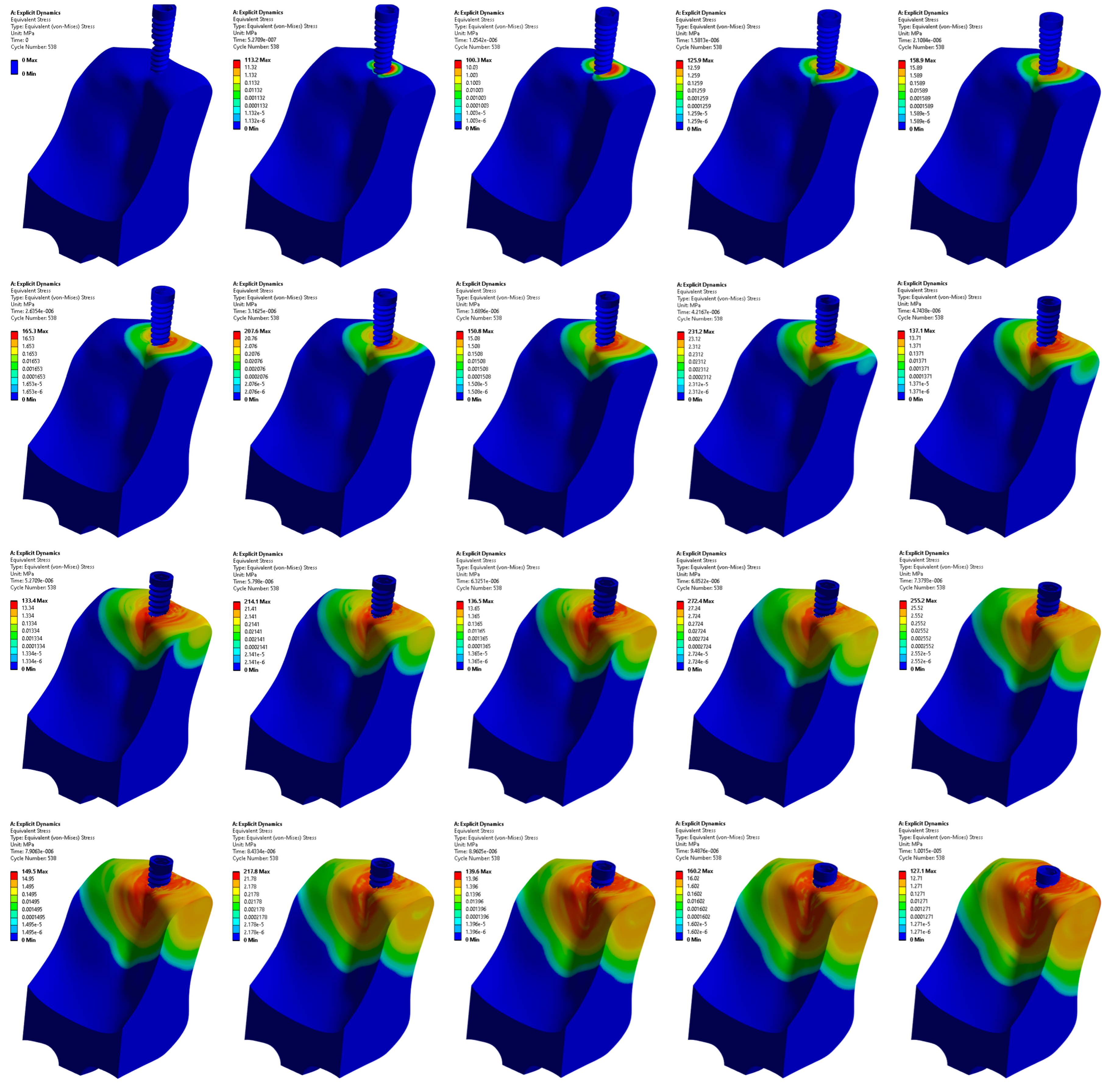
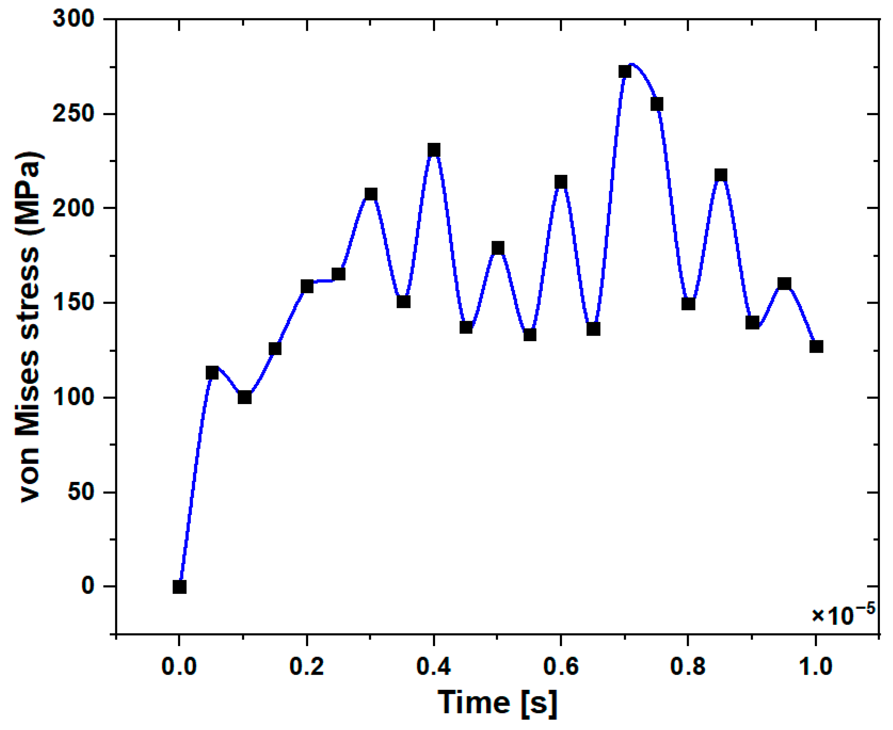
3.1. Stress Distribution in the Jawbone

Figure 5 presents a representation of the stress distribution within the cancellous bone during the progressive insertion of a dental implant into a pre-drilled site. Here, the pre-drilled site is assumed to be a straight hole. This assumption simplifies the modeling process and allows the examination of stress distribution without introducing additional geometric complexities. As the implant progresses into the cancellous bone, a large amount of stress develops in and around the pre-drilled site. This stress is influenced by the interaction between the implant and the geometric features of the pre-drilled site. The stress distribution is attributed to the specific geometry and design of the dental implant. The non-straight geometry of the implant contributes to the uneven distribution of stresses, affecting the implant’s interaction with the surrounding cancellous bone. The analysis results show that the maximum stresses reached 272.4 MPa at the end of the implant insertion process when the implant reached the bottom of the drilled site. This peak stress level reflects the most significant loading conditions during the procedure. At the beginning of the insertion process, when the implant first contacts the bone surface, stresses were recorded at 113.2 MPa. The description attributes this initial stress level to the design of the implant, emphasizing that the implant is not straight in geometry. Figure 5 also shows that stress will increase as the implant progresses into the bone.
When the implant initially makes contact with the bone surface within the pre-drilled hole, a stress of 113.2 MPa is recorded, as shown in Figure 6. This initial stress is attributed to the geometrical constraints, emphasizing that the design and shape of the implant influence the stress response during the early stages of implant insertion. As the implant progresses into the pre-drilled hole, it encounters dimensional variation and biomechanical conditions. The stresses within the cancellous bone advance dynamically as the implant navigates through the hole. Toward the end of the specified simulation time, the implant reaches the bottom surface of the pre-drilled hole. This moment represents the conclusion of the implant insertion process. The collision with the bottom surface leads to a maximum stress recorded at 272.4 MPa.

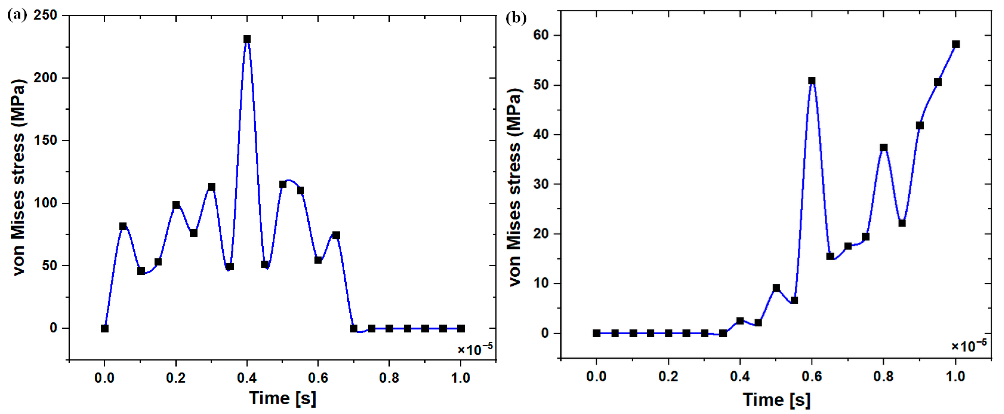
3.2. Stress Distribution at the Upper and Lower Edge of the Pre-Drilled Hole

Figure 7a,b represent the stress distribution at the upper and lower edge of the pre-drilled site during the implant insertion procedure. At the upper edge of the pre-drilled site, the initial stress magnitude recorded is 81.411 MPa as the implant travels into the hole. This stress occurs up to 0.1E-5 s due to the taper dimension in the implant. As the implant crosses the mid-length of the fixture, a large contact takes place, leading to a maximum stress of 113.06 MPa at the upper edge of the pre-drilled hole in the jawbone (Figure 7a). This peak stress occurs due to the contact conditions during this phase of implant insertion. The maximum values of von Mises stresses are found in the drilled zone. At the lower edge of the pre-drilled site, a stress magnitude of 50.928 MPa is recorded after the mid-length of the fixture. At the end of the simulation, as the implant touches the base of the pre-drilled site, the maximum stress at the lower edge is recorded as 58.293 MPa (Figure 7b). It was found that the recorded stress is almost less at the upper edge as the implant reaches the lower part, but vice versa on the lower edge.

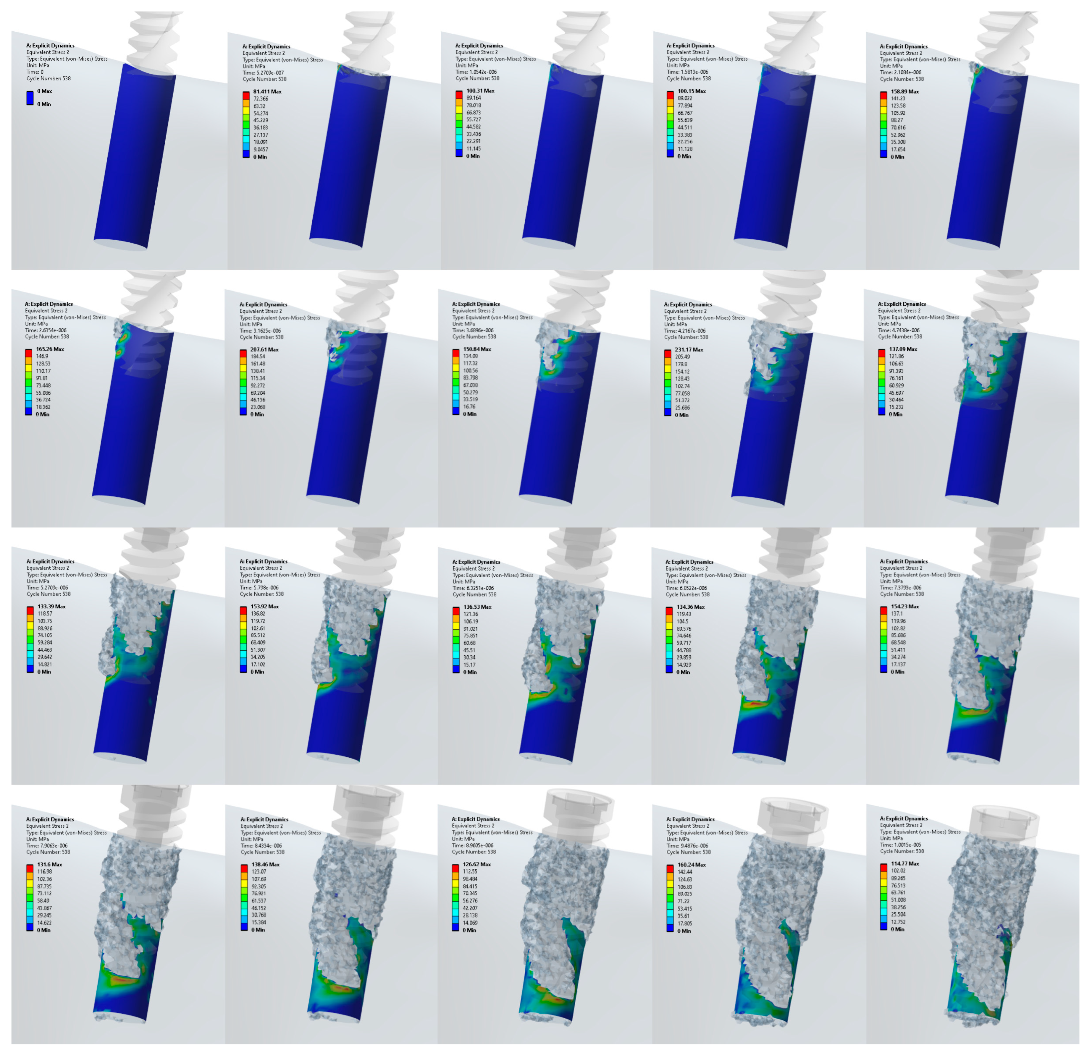
3.3. Stress Distribution at the Surface Area of the Pre-Drilled Site during the Implant Insertion

Figure 8 illustrates the stress distribution at the pre-drilled surface as the implant is inserted. This is a critical aspect of biomechanical analysis during dental implant placement, as it helps to understand the stress transmission to the surrounding bone. The maximum stress is observed after the mid-fixture point as the implant progresses towards the end. The peak stress value recorded was 231.17 MPa, and this occurred at a specific time of 0.8 E-5 s into the simulation. At the initial stage of contact with the pre-drilled surface (at time 0.1 E-5 s), the stress was recorded at 81.44 MPa. This initial stress level reflects the immediate load transfer and contact conditions as the fixture engages with the bone surface. As the fixture rotates, the stress at the pre-drilled surface decreases. There is a variation in the stress value observed. This variation in stress is due to changes in the orientation as the rotational force is applied for the insertion of an implant.
The discussion reiterates that maximum stresses were obtained as the implant reached the middle of the fixtures during the insertion process. Figure 9 illustrates the variation in stresses as rotation is applied to move the implant into the pre-drilled site. This dynamic analysis highlights the stress change with the rotational movement of the implant. The key observation is that the maximum stresses are obtained as the implant moves to the lower end of the hole. This suggests that the biomechanical response intensifies towards the bottom of the pre-drilled site. The tapered design of the implant, where the upper portion of the fixture is wider and the hole is straight, contributes to the observed stress variations. This design characteristic influences the contact areas and load distribution during insertion. The stress distribution analysis, as indicated in Figure 8 and reiterated in the current description, notes that the upper portion of the fixture is wider, while the lower portion of the hole has more contact. This asymmetry contributes to the observed stress patterns. Due to the taper in design, stresses rise at the highest point, emphasizing the influence of implant geometry on stress distribution.

4. Discussion

Both bone and dental implants exhibit intricate and complex geometries that make it challenging to derive analytical solutions for stress distribution. The finite element method is indeed a powerful and widely used numerical technique for addressing such complexities and conducting detailed analyses. A stress overload can result in resorption and implant failure. Resorption is one of the factors that is caused by the excessive energy generated during implant insertion. The long-term success or failure of an implant is significantly influenced by the stress distributed and transferred to the adjacent bone.
In the current study, the stress levels observed at the initial contact and the maximum recorded stress are directly linked to the non-straight geometry of the implant. The implant’s design has a substantial impact on the stress distribution within the cancellous bone during the insertion procedure. Similar observations are reported by Mahendra et al. [33] in their study concerning tapered dental implant designs. In the implant design, due to friction, the implant fixtures exert higher forces and energy to fix the implant in the predetermined position. This leads to peaks and valleys in the stress distribution. In the current study, it was observed that the stress variation takes place as the implant moves into the pre-drilled hole. This is because of the contact between the bone and the fixture on the implant. We considered only the cancellous bone for the analysis. The report by Aslam et al. [34] showed that, due to frictional forces, the implant exerts a maximum load on cancellous bone [35] when compared to cortical bone. The stress distribution patterns at the upper and lower edges provide valuable biomechanical information regarding the length and edges of the pre-drilled hole. The maximum values of von Mises stresses are found in the drilled zone. Similar observations are reported by Fernande et al. [29]. This can be neutralized by optimizing the implant design. The upper edge of the predrilled site shows that the stresses are more at the crestal region of the implant due to the surface area and the speed of the implant insertion. Di Stefano et al. [36] and Demirbas et al. [37] reported similar observations in their investigation.
It also observed that there is a gradual increase in the stress level as the implant reaches the lower edge from the top edge. This is because of the concept of mechanical interlocking. It is the physical engagement or interconnection between the implant surface and the surrounding bone tissue. Mechanical interlocking enhances the stability and fixation of the implant within the bone. A similar interlocking phenomenon is explored by Li et al. [38].
As the implant advances into the cancellous bone, a substantial amount of stress accumulates in and around the pre-drilled site. This stress is influenced by the interplay between the implant and the geometric characteristics of the pre-drilled site. The distribution of stress is directly associated with the unique geometry and design of the dental implant. This observation aligns with the findings of Yang et al. [39], who illustrated that the highest concentration of stress occurs at the point of contact with the implant.

Limitations

The study opted not to include cortical bone in the modeling for simplification purposes. While cortical bone is an integral part of the bone structure, its exclusion simplifies the analysis and may be justified depending on the study’s specific focus or the desired level of computational complexity. The modeling approach considers the full 360 degree surrounding area of the bone to capture the complete effect of implant insertion. This choice allows for a comprehensive analysis of stress distribution and biomechanical interactions from all sides, providing a holistic view of the implant’s impact on the surrounding bone. Excluding thermal effects simplifies the model and assumes that the insertion process does not generate significant heat. While this may be reasonable in some scenarios, certain applications or materials might warrant consideration of thermal effects. The Cowper–Symonds material model is commonly used for modeling mechanical behavior. Its non-thermal nature implies that temperature-related effects are not taken into account. This simplification is suitable when thermal considerations are not a primary focus. In addition, the pre-drilled hole is assumed to be straight.

5. Conclusions

The relationship between the non-straight geometry of the dental implant and the pre-drilled site results in stress distribution within the cancellous bone. Stress analysis is valuable for clinicians and researchers in the field of implantology. Accepting the stress distribution during implant placement helps optimize implant designs, refine surgical techniques, and consider factors that may affect the long-term success and stability of the implant-bone interface. The observation of peaks and valleys in the stress distribution during implant insertion, attributed to the fixture design, serves as a foundation for improving the biomechanical compatibility of dental implants. The detailed stress distribution analysis at the upper and lower edges of the pre-drilled site provides a nuanced understanding of the mechanical interactions between the implant and the jawbone. The described stress variations during rotational movement underscore the complexity of biomechanical interactions in dental implantology. The interplay between implant design, rotation, and stress distribution informs ongoing efforts to enhance implant performance and optimize clinical outcomes. Clinicians can use this information to anticipate and address potential stress-related challenges during implant placement. Considerations for taper dimensions, mid-length contact, and stress distribution patterns can inform decisions in the planning and execution of implant procedures.

Supplementary Materials

The following supporting information can be downloaded at: https://www.mdpi.com/article/10.3390/prosthesis6020023/s1, Video S1: Stresses in Mandibular Jawbone during Implant Insertion.

Author Contributions

Conceptualization, L.G.K., C.K.N. and A.E.; methodology, A.E. and N.S.; software, L.G.K. and C.K.N.; validation, L.G.K., C.K.N. and N.S.; formal analysis, L.G.K.; investigation, C.K.N. and L.G.K.; resources, M.F., D.D.S., A.E. and N.S.; data curation, L.G.K. and C.K.N.; writing (original draft preparation), C.K.N. and L.G.K.; writing (review and editing), L.G.K., N.S., A.E. and N.S.; visualization, C.K.N., M.F. and D.D.S.; supervision, M.F. and D.D.S.; project administration, L.G.K. All authors have read and agreed to the published version of the manuscript.

Funding

This research received no external funding.

Institutional Review Board Statement

Not applicable.

Informed Consent Statement

Not applicable.

Data Availability Statement

Data are contained within the article and Supplementary Materials.

Acknowledgments

The authors would like to thank the Department of Aeronautical and Automobile Engineering, Manipal Institute of Technology Manipal, Manipal Academy of Higher Education, Manipal, for the computing resources provided to carry out this work.

Conflicts of Interest

The authors declare no conflicts of interest.

References

  1. Matos, G.R.M. Surface Roughness of Dental Implant and Osseointegration. J. Maxillofac. Oral Surg. 2021, 20, 1–4. [Google Scholar] [CrossRef] [PubMed]
  2. Smeets, R.; Stadlinger, B.; Schwarz, F.; Beck-Broichsitter, B.; Jung, O.; Precht, C.; Kloss, F.; Gröbe, A.; Heiland, M.; Ebker, T. Impact of Dental Implant Surface Modifications on Osseointegration. Biomed. Res. Int. 2016, 2016, 6285620. [Google Scholar] [CrossRef]
  3. Rittel, D.; Dorogoy, A.; Shemtov-Yona, K. Modeling the effect of osseointegration on dental implant pullout and torque removal tests. Clin. Implant Dent. Relat. Res. 2018, 20, 683–691. [Google Scholar] [CrossRef] [PubMed]
  4. Yi, Y.A.; Park, Y.B.; Choi, H.; Lee, K.W.; Kim, S.J.; Kim, K.M.; Oh, S.; Shim, J.S. The Evaluation of Osseointegration of Dental Implant Surface with Different Size of TiO2 Nanotube in Rats. J. Nanomater. 2015, 2015, 581713. [Google Scholar] [CrossRef]
  5. Rosa, C.D.; Bento, V.A.; Duarte, N.D.; Sayeg, J.M.; Santos, T.J.; Pellizzer, E.P. Do dental implants installed in different types of bone (I, II, III, IV) have different success rates? A systematic review and meta-analysis. Saudi Dent. J. 2023, in press. [Google Scholar] [CrossRef]
  6. Olmedo-Gaya, M.V.; Romero-Olid, M.N.; Ocaña-Peinado, F.M.; Vallecillo-Rivas, M.; Vallecillo, C.; Reyes-Botella, C. Influence of different surgical techniques on primary implant stability in the posterior maxilla: A randomized controlled clinical trial. Clin. Oral Investig. 2023, 27, 3499–3508. [Google Scholar] [CrossRef]
  7. Huang, Y.M.; Chou, I.-C.; Jiang, C.-P.; Wu, Y.-S.; Lee, S.-Y. Finite Element Analysis of Dental Implant Neck Effects on Primary Stability and Osseointegration in a Type IV Bone Mandible. Biomed. Mater. Eng. 2014, 24, 1407–1415. [Google Scholar] [CrossRef] [PubMed]
  8. Paracchini, L.; Barbieri, C.; Redaelli, M.; Di Croce, D.; Vincenzi, C.; Guarnieri, R. Finite Element Analysis of a New Dental Implant Design Optimized for the Desirable Stress Distribution in the Surrounding Bone Region. Prosthesis 2020, 2, 225–236. [Google Scholar] [CrossRef]
  9. Cicciù, M.; Cervino, G.; Terranova, A.; Risitano, G.; Raffaele, M.; Cucinotta, F.; Santonocito, D.; Fiorillo, L. Prosthetic and mechanical parameters of the facial bone under the load of different dental implant shapes: A parametric study. Adv. Surg. Med. Spec. 2019, 1, 41–53. [Google Scholar] [CrossRef]
  10. Udomsawat, C.; Rungsiyakull, P.; Rungsiyakull, C.; Khongkhunthian, P. Comparative study of stress characteristics in surrounding bone during insertion of dental implants of three different thread designs: A three-dimensional dynamic finite element study. Clin. Exp. Dent. Res. 2019, 5, 26–37. [Google Scholar] [CrossRef]
  11. Juneja, S.; Miranda, G.; Eram, A.; Shetty, N.; Chethan, K.N.; Keni, L.G. Investigating the Influence of All-Ceramic Prosthetic Materials on Implants and Their Effect on the Surrounding Bone: A Finite Element Analysis. Prosthesis 2024, 6, 74–88. [Google Scholar] [CrossRef]
  12. Wachol, K.; Morawiec, T.; Nowak-Wachol, A.; Kubaszek, B.; Kasprzyk-Kucewicz, T.; Baldi, D.; Machorowska-Pieniążek, A.; Skucha-Nowak, M.; Cholewka, A. Comparative Analysis of Implant Prosthesis Treatment Planning and Execution Following Bone Repair Procedures Using Dynamic Surgical Navigation in Augmented Areas. Coatings 2022, 12, 1099. [Google Scholar] [CrossRef]
  13. Shetty, M.; Prasad, D.K.; Mehra, D.R. Anatomical Considerations in Implant Selection and Positioning. Int. J. Oral Implantol. Clin. Res. 2013, 4, 24–29. [Google Scholar] [CrossRef]
  14. Fiorillo, L.; Milone, D.; D’Andrea, D.; Santonocito, D.; Risitano, G.; Cervino, G.; Cicciù, M. Finite Element Analysis of Zirconia Dental Implant. Prosthesis 2022, 4, 490–499. [Google Scholar] [CrossRef]
  15. do Vale Souza, J.P.; de Moraes Melo Neto, C.L.; Piacenza, L.T.; Freitas da Silva, E.V.; de Melo Moreno, A.L.; Penitente, P.A.; Brunetto, J.L.; Dos Santos, D.M.; Goiato, M.C. Relation Between Insertion Torque and Implant Stability Quotient: A Clinical Study. Eur. J. Dent. 2021, 15, 618–623. [Google Scholar] [CrossRef]
  16. Dorogoy, A.; Rittel, D.; Shemtov-Yona, K.; Korabi, R. Modeling dental implant insertion. J. Mech. Behav. Biomed. Mater. 2017, 68, 42–50. [Google Scholar] [CrossRef]
  17. Lo Giudice, R.; Machado, P.S.; Dal Piva, A.M.; Tribst, J.P. Influence of Placement of Ultrashort Implant at Sub-Crestal, Crestal and Supra-Crestal Level with Titanium or Polyetheretherketone Hybrid Abutment: 3D Finite Element Analysis. Prosthesis 2023, 5, 721–732. [Google Scholar] [CrossRef]
  18. Wolff, J. The Law of Bone Remodelling; Springer: Berlin/Heidelberg, Germany, 1986. [Google Scholar]
  19. Reginald, J.; Kalayarasan, M.; Chethan, K.N.; Dhanabal, P. Static, dynamic, and fatigue life investigation of a hip prosthesis for walking gait using finite element analysis. Int. J. Model. Simul. 2023, 43, 797–811. [Google Scholar] [CrossRef]
  20. Göktaş, H.; Subaşi, E.; Uzkut, M.; Kara, M.; Biçici, H.; Shirazi, H.; Chethan, K.N.; Mihçin, Ş. Optimization of Hip Implant Designs Based on Its Mechanical Behaviour. In Biomechanics in Medicine, Sport and Biology; Springer: Berlin/Heidelberg, Germany, 2022; pp. 37–43. [Google Scholar]
  21. Eram, A.; Zuber, M.; Keni, L.G.; Kalburgi, S.; Naik, R.; Bhandary, S.; Amin, S.; Badruddin, I.A. Finite element analysis of immature teeth filled with MTA, Biodentine and Bioaggregate. Comput. Methods Programs Biomed. 2020, 190, 105356. [Google Scholar] [CrossRef]
  22. Shaikh, N.; Shenoy, B.S.; Bhat, N.S.; Shetty, S.; Chetan, K.C. Wear estimation at the contact surfaces of oval shaped hip implants using finite element analysis. Cogent Eng. 2023, 10, 2222985. [Google Scholar] [CrossRef]
  23. Gutmann, C.; Shaikh, N.; Shenoy, B.S.; Bhat, N.S.; Keni, L.G.; Chetan, K.C. Wear estimation of hip implants with varying chamfer geometry at the trunnion junction: A finite element analysis. Biomed. Phys. Eng. Express 2023, 9, 035004. [Google Scholar] [CrossRef] [PubMed]
  24. Blume, O.; Wildenhof, J.; Otto, S.; Probst, F. Influence of Clinical Parameters on the Primary Stability of a Tapered Dental Implant: A Retrospective Analysis. Int. J. Oral Maxillofac. Implants 2021, 36, 762–770. [Google Scholar] [CrossRef] [PubMed]
  25. Fernandes, M.G.A.; Fonseca, E.M.M.; Natal, R.J. Thermal analysis during bone drilling using rigid polyurethane foams: Numerical and experimental methodologies. J. Braz. Soc. Mech. Sci. Eng. 2016, 38, 1855–1863. [Google Scholar] [CrossRef]
  26. Prasannavenkadesan, V.; Pandithevan, P. An in-silico bone drilling protocol to control thrust forces using finite element analysis coupled with the constitutive models. Proc. Inst. Mech. Eng. Part C J. Mech. Eng. Sci. 2021, 236, 8201–8210. [Google Scholar] [CrossRef]
  27. Khoddami, A.S.; Nasiri, M.A.; Mohammadi, B. Experimental and numerical study on micro-blasting process of 3A dental implant titanium alloy: A comparison between finite element method and smoothed particle hydrodynamics. J. Mech. Behav. Biomed. Mater. 2022, 132, 105269. [Google Scholar] [CrossRef] [PubMed]
  28. Škrlec, A.; Klemenc, J. Estimating the Strain-Rate-Dependent Parameters of the Cowper-Symonds and Johnson-Cook Material Models using Taguchi Arrays. Strojniški Vestn. J. Mech. Eng. 2016, 62, 220–230. [Google Scholar] [CrossRef]
  29. Fernandes, M.G.; Fonseca, E.M.; Jorge, R.N. Thermo-mechanical stresses distribution on bone drilling: Numerical and experimental procedures. Proc. Inst. Mech. Eng. Part L J. Mater. Des. Appl. 2019, 233, 637–646. [Google Scholar] [CrossRef]
  30. ANSYS LS-DYNA User’s Guide. 2023. Available online: https://ftp.lstc.com/anonymous/outgoing/web/ls-dyna_manuals/DRAFT/DRAFT_Theory.pdf (accessed on 15 October 2023).
  31. Prasannavenkadesan, V.; Pandithevan, P. Johnson–Cook Model Combined with Cowper–Symonds Model for Bone Cutting Simulation with Experimental Validation. J. Mech. Med. Biol. 2021, 21, 2150010. [Google Scholar] [CrossRef]
  32. Li, Z.; Kindig, M.W.; Kerrigan, J.R.; Untaroiu, C.D.; Subit, D.; Crandall, J.R.; Kent, R.W. Rib fractures under anterior–posterior dynamic loads: Experimental and finite-element study. J. Biomech. 2010, 43, 228–234. [Google Scholar] [CrossRef]
  33. Mahendra, J.; Chand, Y.B.; Mahendra, L.; Fageeh, H.N.; Fageeh, H.I.; Ibraheem, W.; Alzahrani, K.M.; Alqahtani, N.M.; Alahmari, N.M.; Almagbol, M.; et al. Evaluation of Stress Distribution during Insertion of Tapered Dental Implants in Various Osteotomy Techniques: Three-Dimensional Finite Element Study. Materials 2021, 14, 7547. [Google Scholar] [CrossRef]
  34. Aslam, A.; Hassan, S.H.; Aslam, H.M.; Khan, D.A. Effect of platform switching on peri-implant bone: A 3D finite element analysis. J. Prosthet. Dent. 2019, 121, 935–940. [Google Scholar] [CrossRef]
  35. Niroomand, M.R.; Arabbeiki, M. Implant stability in different implantation stages: Analysis of various interface conditions. Informatics Med. Unlocked 2020, 19, 100317. [Google Scholar] [CrossRef]
  36. Di Stefano, D.A.; Perrotti, V.; Greco, G.B.; Cappucci, C.; Arosio, P.; Piattelli, A.; Iezzi, G. The effect of undersizing and tapping on bone to implant contact and implant primary stability: A histomorphometric study on bovine ribs. J. Adv. Prosthodont. 2018, 10, 227. [Google Scholar] [CrossRef] [PubMed]
  37. Demirbas, A.E.; Ekici, R.; Karakaya, M.; Alkan, A. Bone stress and damage distributions during dental implant insertion: A novel dynamic FEM analysis. Comput. Methods Biomech. Biomed. Eng. 2022, 25, 1381–1392. [Google Scholar] [CrossRef] [PubMed]
  38. Li, J.; Jansen, J.A.; Walboomers, X.F.; van den Beucken, J.J. Mechanical aspects of dental implants and osseointegration: A narrative review. J. Mech. Behav. Biomed. Mater. 2020, 103, 103574. [Google Scholar] [CrossRef] [PubMed]
  39. Yang, Y.; Liu, Y.; Yuan, X.; Ren, M.; Chen, X.; Luo, L.; Zheng, L.; Liu, Y. Three-dimensional finite element analysis of stress distribution on short implants with different bone conditions and osseointegration rates. BMC Oral Health 2023, 23, 220. [Google Scholar] [CrossRef]
Figure 1. Simulation model.
Prosthesis 06 00023 g001
Figure 2. Meshed model.
Prosthesis 06 00023 g002
Figure 3. Grid independence study.
Prosthesis 06 00023 g003
Figure 4. Applied boundary conditions for the jawbone and implant.
Prosthesis 06 00023 g004
Figure 5. Stress distribution in the jawbone during implant insertion.
Prosthesis 06 00023 g005
Figure 6. Stress distribution in the jawbone.
Prosthesis 06 00023 g006
Figure 7. Stress distribution at the pre-drilled holes (a) upper edge (b) lower edge.
Prosthesis 06 00023 g007
Figure 8. Stress distribution at the pre-drilled hole surface.
Prosthesis 06 00023 g008
Figure 9. Stress variation at the pre-drilled surface.
Prosthesis 06 00023 g009
Table 1. Details of models and corresponding nodes and elements for each model.
ComponentsNodeElements
Cancellous bone1,216,8887,010,160
Implant15,32272,020
Table 2. Material properties and Cowper–Symonds parameters [29,31,32].
PropertiesCancellous BoneImplant
Density (Kg/m3)8007856
Young’s Modulus (MPa)987220
Poisson’s ratio0.30.3
Initial yield stress (MPa)23-
Tangent modulus (MPa)0.91-
Hardening Parameter0.1-
C2.5-
P7-
Failure strain0.05-
Disclaimer/Publisher’s Note: The statements, opinions and data contained in all publications are solely those of the individual author(s) and contributor(s) and not of MDPI and/or the editor(s). MDPI and/or the editor(s) disclaim responsibility for any injury to people or property resulting from any ideas, methods, instructions or products referred to in the content.

