Article

Effect of Polarization on Cross-Spectral Density Matrix

by
Akanksha Gautam
1,
Dinesh N. Naik
2,
C. S. Narayanamurthy
2 and
Rakesh Kumar Singh
1,*
1
Laboratory of Information Photonics and Optical Metrology, Department of Physics, Indian Institute of Technology (Banaras Hindu University), Varanasi 221005, Uttar Pradesh, India
2
Applied and Adaptive Optics Laboratory, Department of Physics, Indian Institute of Space Science and Technology, Thiruvananthapuram 695547, Kerala, India
*
Author to whom correspondence should be addressed.
Photonics 2024, 11(2), 142; https://doi.org/10.3390/photonics11020142
Submission received: 11 December 2023 / Revised: 25 January 2024 / Accepted: 1 February 2024 / Published: 3 February 2024
(This article belongs to the Special Issue Diffractive Optics – Current Trends and Future Advances)

Abstract

:
Coherence-polarization properties of different beams are experimentally measured in the far-field from the source and results are presented for incoherent sources with three different polarization features, such as unpolarized, diagonally polarized, and spatially depolarized. These results highlight the role of polarization tailoring on far-field coherence-polarization properties of the incoherent vector source. The effect of polarization on far-field coherence is analyzed using a beam cross-spectral density (CSD) matrix, and the role of polarization tailoring on the CSD matrix is demonstrated. Two-dimensional spatial distributions of all four elements of the CSD matrix are experimentally realized using a field-based interferometer with Sagnac geometry in combination with a four-step phase-shifting technique.

1. Introduction

Light beam shaping involves controlling the characteristics of light in its different degrees of freedom, such as in time, space, and polarization. Shaped beams exhibit remarkable physical properties during their propagation and interactions with matter [1,2]. Consequently, these beams find extensive applications across various fields, including optical communications, optical trapping and tweezing, metrology, imaging, etc. [3]. To reshape the profile of a light beam for specific applications, tools like liquid-crystal spatial light modulators [4], digital micromirror devices [5], metamaterials [6], nonlinear elements [7], geometric phase elements like q-plate [8], and specially designed laser cavities [9] have been widely used. Beam shaping has been mainly accomplished for fully coherent light sources. Nevertheless, a low coherence beam and its shaping are desired for various reasons. For instance, when fully coherent-shaped beams propagate through turbulent atmospheres, they suffer from distortion, scintillation, and beam wander, further degrading the beam quality [10]. Lowering spatial coherence effectively reduces coherent artifacts and offers greater controllability in light beam shaping compared to fully coherent beams [11]. Spatial coherence, one of the fundamental properties of light, is the description of the statistical correlation between fields at a pair of spatial points [12]. With growing interest in low-coherence sources, numerous techniques for synthesizing correlation structures have emerged. Among partially coherent beams, those featuring a Schell model structure are the most widely used. In these beams, the spatial coherence structure is determined by the spatial separation between two positions. Significant synthesized Schell model sources are Laguerre–Gaussian correlated [13,14], Bessel–Gaussian correlated [15], Hermite–Gaussian correlated [16], and multi-Gaussian correlated [17]. Other than these correlation functions, some other synthesis methods include non-uniform correlated sources [18,19], correlation holography [20,21], and other different exotic structures [22,23,24,25].
In recent years, an enormous amount of interest has grown in electromagnetic or vector fields with inhomogeneous polarization. These fields exhibit the influence of coherence and polarization, wherein different field components may show varying coherence properties [26]. The coherence and polarization characteristics of such fields have been observed to be inherently intertwined [27,28]. For a complete explanation of the statistical properties of these random vectorial light fields, the electromagnetic coherence theory is thoroughly developed [12,28]. In the space–frequency domain, the central quantity for characterizing the vectorial light field is a 2 × 2 cross-spectral density (CSD) matrix having four elements. The CSD matrix provides solutions to numerous unresolved problems in optics [29,30]. These fields have found a wide range of applications in optical imaging [31], super-resolution imaging [32], optical trapping [33], classification of biological samples [34], microscopy [35,36], surface plasmon structuring [37], etc. These properties arise because of the extensive tailoring potential of these vectorial fields, offering precise control over beam shape, polarization, and coherence, not only at the source plane but also in other regions. Many attempts have been made to synthesize vectorial coherence, including electromagnetic Gaussian–Schell model sources [38,39], special correlation functions [40], and vectorial coherence holography [41]. Different techniques have been developed to tailor and examine vectorial coherence using liquid crystal spatial light modulators [42,43,44,45]. Complete access and adaptive control over the orthogonal polarization components of light helps in creating the desired vectorial coherence.
To access and analyze coherence structures, it is important to experimentally measure complex coherence, which is not a directly observable quantity like intensity. The visibility of the intensity fringes in Young’s two-pinhole interference experiment has historically been used to measure the coherence of light [12]. A similar approach is also extended to the polarization domain to characterize the vector light field [46,47]. Although Young’s interferometer is conceptually simple, it possesses certain inherent limitations. The most prominent of these limitations is the low light efficiency of Young’s two-pinhole setup, which poses challenges for characterizing weak light fields. Additionally, sequential scanning for point sampling is extremely time consuming. Alternative methods relying on the concept of Young’s approach have been developed to address some of these limitations [48,49]. Another method based on the Hanbury Brown–Twiss (HBT) experiment was introduced for random vector light fields following Gaussian statistics. The method used intensity correlations to determine the amplitude of the two-point field correlation [50]. Later, a method was proposed to retrieve the complete information of the complex coherence function by adding a reference random light field and using the intensity correlation [51]. This approach was also extended to the vector source [52]. In another development, the concept of generalized HBT was introduced and experimental results were presented on the measurement of complex coherence functions of the scalar and vector light [53,54]. Cai et al. discussed and experimentally demonstrated the synthesis and measurement of complex correlation matrix of the specially correlated radially polarized (SCRP) vector source [54]. This method involved combining the incoherent vector beam with a pair of fully coherent reference beams and analyzing the intensity–intensity cross-correlation of the recorded patterns. Recently, another alternative method has been introduced by Cai and his group for measuring the elements of the CSD matrix of the SCRP vector beam using self-referencing holography [55]. In this technique, a spatial light modulator introduces phase perturbations at a reference point set inside the regions of the test beam. The interaction between the light from the perturbed point and the overall plane leads to interference intensity patterns at the Fourier plane, which unveils information about the CSD matrix elements. Other than these, most recently our group developed a technique to measure the CSD matrix based on a shearing interferometer [56] and an intensity interferometer [57].
The exploration of light’s polarization state encompasses both uniform and non-uniform characteristics. In the case of non-uniform polarization, the polarization state may vary in space over the beam’s profile with various features, such as periodic variations [58,59,60], circular symmetry [61], or other complex structures [62,63,64]. Many intriguing properties have been elucidated for such non-uniformly polarized beams, particularly as they propagate in free space, random media, or through optical systems [65,66]. Consequently, substantial efforts have been dedicated to comprehensively characterize them and to design and experimentally generate beams with diverse states of coherence and polarization over the past few years. One of the methods to generate such a non-uniformly polarized beam with transverse polarization periodicity is by using a double-wedge depolarizer (DWD). A DWD is comprised of a pair of uniaxial crystal wedges, each having its optic axis oriented at an angle relative to the other. The DWD behaves as a spatial polarization state scrambler and induces a periodic variation in the polarization state across the transverse plane [59]. Until now, extensive research has been conducted to investigate various characteristics of light as it passes through the DWD, primarily driven by its unique polarizing properties. Single-point correlation parameters such as the Stokes parameter (SP) have played a fundamental role in characterizing the polarization. The SPs of a DWD were initially investigated for both polarized and unpolarized monochromatic beams, revealing the Talbot effect [59]. Subsequently, the polarization features of DWD were investigated concerning partially coherent vector beams propagating through it. Additionally, the reappearance of the Talbot effect was observed, like the case of monochromatic vector light [67,68]. The DWD has also been used with a partially coherent super-luminescent diode source to generate a spatio-spectral coherence structure. Furthermore, the spectral coherence SP in one dimension was measured using Young’s interferometer based on a digital micromirror device [69].
In this paper, we analyze the role of source polarization on far-field coherence-polarization of the incoherent source by measuring the two-dimensional spatial distributions of the CSD matrix elements. Here, we use a light-emitting diode (LED) as an incoherent source and tailor its polarization for two different cases, namely a diagonally polarized and spatially depolarized beams, respectively. Spatial depolarization in the incoherent source is realized by using a double-wedge depolarizer (DWD) due to its special polarization features. For comparison of the tailored polarization features of the LED source, we also present results for unpolarized LED sources. Unlike a point source, an LED features an enlarged light-emitting surface. Each point of the extended LED source acts as an independent light scatterer and there exists no correlation between any two points. Hence, such sources are in general incoherent with unpolarized light [11,12]. For complete analysis of the CSD matrix elements, we build a highly stable Sagnac radial shearing interferometer to measure the second-order field correlations of the vector source. The CSD matrix elements are measured as the complex spatial coherence function, which is obtained from the digitally constructed visibility and phase from four phase-shifted interferograms. Phase shifts in our experimental configuration are realized by introducing geometric phase shifts in the interfering beams [70]. Hence, the study investigates the impact of polarization states of input light on the elements of the CSD matrix. A detailed discussion of the theoretical basis, experimental design, and results is presented below.

2. Principle

Consider a planar, stochastic transverse electromagnetic light beam propagating along the longitudinal z -direction. The second-order statistical characteristics of this stochastic electromagnetic light field in the space–frequency domain, at angular frequency ω and two spatial positions, namely ρ 1 = ( x 1 , y 1 ) and ρ 2 = ( x 2 , y 2 ), are described by the CSD matrix as follows [28]:
W ρ 1 ,   ρ 2 ;   ω = W x x ρ 1 ,   ρ 2 ;   ω W x y ρ 1 ,   ρ 2 ;   ω W y x ρ 1 ,   ρ 2 ;   ω W y y ρ 1 ,   ρ 2 ;   ω ,
The matrix elements are represented as follows:
W m n ρ 1 ,   ρ 2 ;   ω = E m * ρ 1 ;   ω E n ρ 2 ;   ω ,
where ( m ,   n )     ( x ,   y ) represents the orthogonal polarization components, and E m ρ is the fluctuating electric field component at point ρ along the m -axis. The asterisk denotes the complex conjugate, and the angle bracket denotes the ensemble average. The individual elements of the 2 × 2 CSD matrix represent the two-point correlation function between the same field components in addition to the different field components.
From the theory of non-negative kernels, the CSD matrix elements should satisfy the non-negative definiteness condition, and the elements are represented as follows [71]:
W m n ρ 1 , ρ 2 ;   ω = p m n υ ;   ω H * ( ρ 1 ,   υ ) H ρ 2 ,   υ d 2 υ ,
where p m n represents the elements of a 2 × 2 matrix, signifying the polarization through the single-point correlation of the incoherent source; and H is a propagation kernel, which connects the output and input transverse plane coordinates ρ and υ , respectively.
For   a   Fourier   kernel   H ρ ,   υ = exp i 2 π λ f ρ . υ ,
where λ is the wavelength of the source, and f is the focal length of Fourier transforming lens L.
From Equations (3) and (4), the CSD matrix of a quasi-monochromatic source at the observation plane is given by the following equation:
W m n ρ 1 , ρ 2 = p m n υ exp i 2 π λ f υ . ρ 2 ρ 1 d υ ,
Our specific choice of the Fourier kernel aligned with our goal to analyze the two-point correlations in the far-field from the source. The spatial distribution of the incoherent vector source is represented as p m n υ , and this quantity is real for diagonal elements, i.e., m = n , but may take a complex value for non-diagonal elements, i.e., m n . Equation (5) represents the vectorial van Cittert–Zernike theorem, showing that the elements of the CSD matrix are represented by the complex spatial coherence function given by the Fourier transform of the incoherent source. The VCZ theorem establishes a connection between the spatial shape and size of an incoherent source and its complex spatial coherence function. Therefore, the complex two-point correlation functions of the vector source at the observation plane relate to the incoherent vector source by the vectorial van Cittert–Zernike (VCZ) theorem [72].
Figure 1 highlights the source structure and far-field configuration of the two-point correlations. A yellow light-emitting diode (LED) source is kept at the front focal plane of lens L of focal length f = 60 mm, and measurement is performed at the back focal plane of lens L, as represented by the black dotted line in Figure 1. To understand the role of polarization tailoring in the far-field coherence properties of the vector source, we considered three different states of polarization of the incoherent source. These states were namely unpolarized, diagonally polarized, and spatially depolarized light sources.
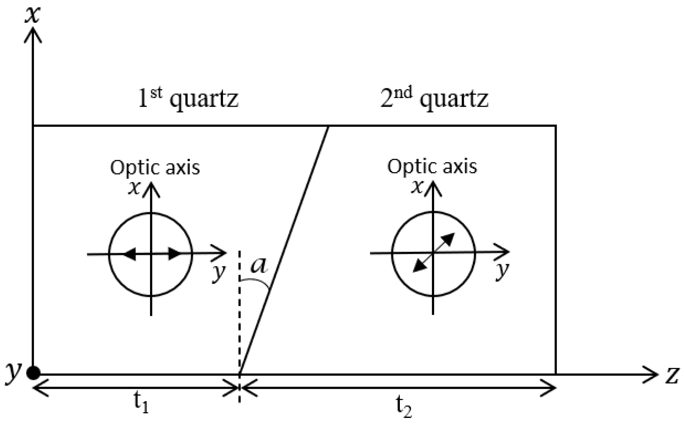
The first polarization state of the source is realized by directly considering the light from the LED source, as shown in Figure 1. The second polarization state is realized by placing a linear polarizer oriented at 45° from its fast axis after the source. Finally, the third polarization state is realized with the DWD (Thorlabs DPU-25-A Quartz-Wedge Achromatic Depolarizer) in the source configuration. The depolarizer, with a thickness of 7.4 mm, contains a broadband anti-reflectance coating that spans from 350 nm to 700 nm. As illustrated in Figure 2, the DWD is comprised of two birefringent quartz wedges (with a wedge angle a = 2.17°) with their optic axes (fast axes) oriented at ξ = 45° relative to each other. The 45° offset enables the plates to spatially depolarize the incoming polarization state. A linearly polarized beam along one plate’s fast axis will undergo polarization changes due to the birefringence of the other plate. Since the plates are wedged, the optical path length through each birefringent plate varies with the beam’s position. Consequently, each point on the aperture exhibits spatially dependent net birefringence and the final polarization state [59]. Therefore, DWD introduces a periodic polarization pattern in the source structure. The mathematics underlying this statement are presented in the below equations [69].
The DWD is considered to be a composition of two wave plates, where the retardation varies with spatial coordinate x . When the DWD is rotated about the z -axis at angle χ with respect to the x -axis, the thicknesses of the quartz wedges are represented as follows:
t 1 ( x ) = x   c o s   χ   t a n a + t 1 ,
and   t 2 ( x ) = x   c o s   χ   t a n a + t 2
where t 1 and t 2 are the center thicknesses of the 1st and 2nd quartz wedges, respectively, at x = y = 0 ; and a is the wedge angle. Therefore, the wedge retardations are given by the following equation:
ψ p ( x ) = 2 π t p ( x )   ( n s n f ) / λ ,   p   { 1 ,   2 }   ,
where n s and n f are the refractive indices of quartz with respect to the slow and fast axes, respectively. Due to the position-dependent retardation, an input beam with uniform polarization would result in an output beam with a spatially periodic polarization modulation with period L = λ / [ ( n s n f ) t a n a ] .
The Jones matrix of an individual quartz wedge with its fast axis directed along the x direction is represented as follows [69]:
M p ( x ) = 1 0 0 e x p   i ψ p ( x )   ,   p   { 1 ,   2 } ,
If the optic axis is oriented such that it forms angle ξ with the x -axis, the Jones matrix is now transformed as follows:
M p ( x   ; ξ p ) = R ( ξ p ) M p ( x ) R ( ξ p ) ,   p   { 1 ,   2 } ,
where
R ( ξ ) = c o s   ξ s i n   ξ s i n   ξ c o s   ξ   ,
R ( ξ ) is the rotational matrix that represents the DWD’s rotation about the z -axis. The overall matrix of the DWD is finally described as follows [69]:
M D W D ( x ; ξ 1 , ξ 2 ) = M 2 ( x ; ξ 2 ) M 1 ( x ; ξ 1 ) ,
When the depolarizer is rotated at angle χ , the resulting matrix becomes:
M D W D , r o t ( x ; ξ 1 , ξ 2 , χ ) = R ( χ ) M D W D ( x ; ξ 1 , ξ 2 ) R ( χ ) ,
Thus, at the output plane of DWD, the Jones vector is given by the following equation:
E o u t p u t M D W D , r o t ( x ; ξ 1 , ξ 2 , χ ) E i ,
where the Jones vector of the incident beam is represented as E i . As a result, we obtain a periodic polarization modulation at the incoherent source due to the properties of the DWD.
The next section describes the use of an interferometer to measure the CSD matrix elements and provide their two-dimensional distribution at the observation plane.

3. Experimental Setup and Description

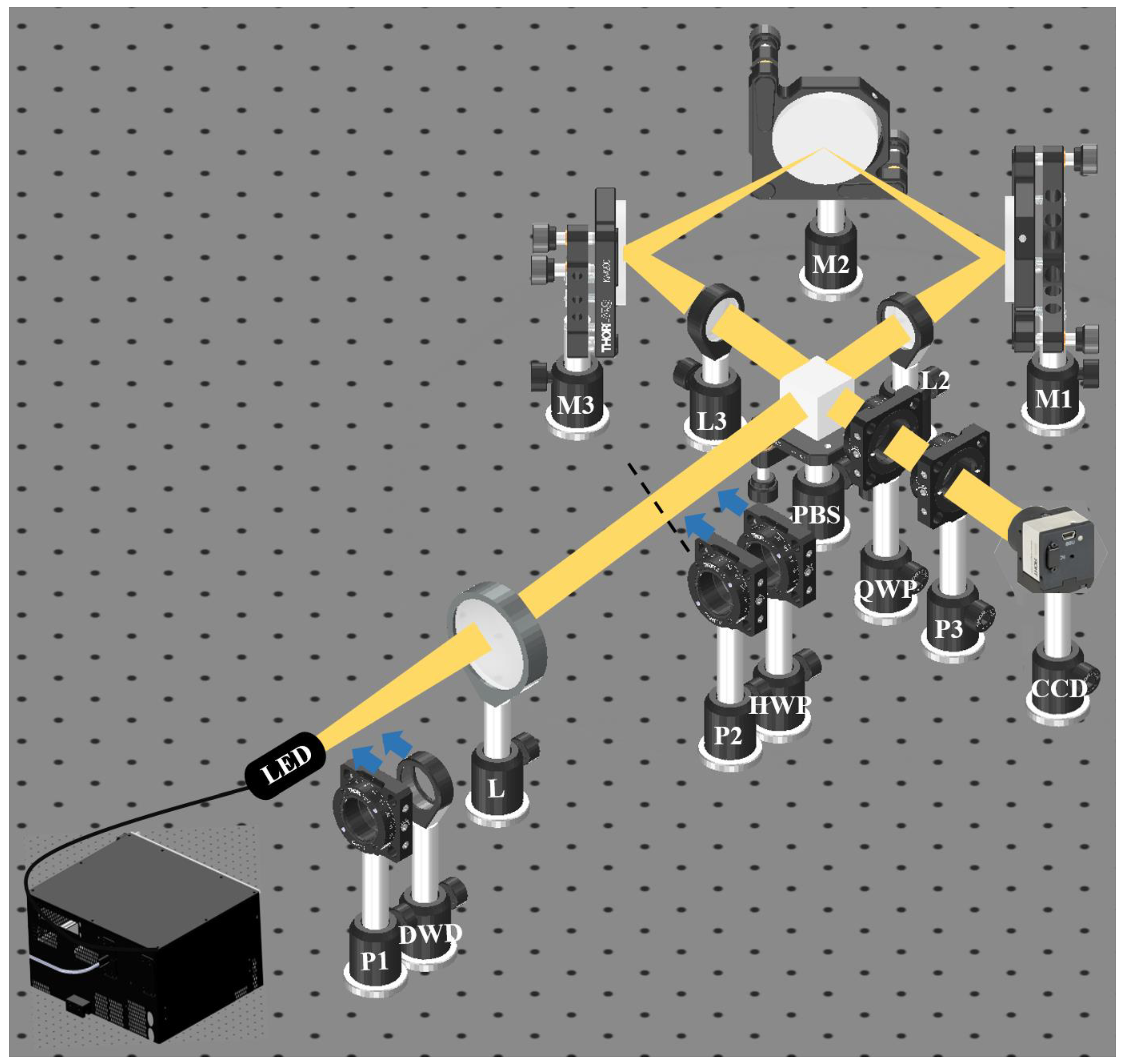
Figure 3 shows the experimental setup to obtain the CSD matrix elements. The initial part of the setup corresponds to the schematic depicted in Figure 1. Here, we capture the two-point far-field correlation at the back focal plane of lens L, marked by the black dotted line in Figure 3. The second part represents the interferometric design to measure the CSD matrix elements and provide their two-dimensional distribution at the observation plane. This interferometer uses a cyclic Sagnac geometry with a radial shearing design. The stochastic field from the source is directed into the interferometer by a polarizing beam splitter (PBS). The PBS splits the incoming beam into two beams with orthogonal x and y polarization states. The two beams counter propagate through a square cyclic path designed by mirrors M1, M2, and M3. Lenses L2 and L3 with focal lengths f2 = 120 mm and f3 = 125 mm, respectively, are introduced in the path of the counter-propagating beams to form a telescopic lens system with magnifications α = f3/f2 = 1.041 and α 1 = f2/f3 = 0.96, respectively, which gives a radial shear between the two beams. Therefore, two copies of the radially sheared fields are obtained at the output of the interferometer. Therefore, the far-field of lens L is imaged onto an 8-bit CMOS camera (Thorlabs, Newton, New Jersey, USA, DCC3240M). At the imaging plane, the interference pattern at arbitrary position ρ arises due to the superposition of the fields from the spatial positions ρ 1 = α 1 ρ and ρ 2 = α ρ of the two copies of the beam. The field points separated by distance Δ ρ = ρ 2 ρ 1 = ( α α 1 ) ρ represent the relative shear among the two fields, which shows a linear relation between the relative shear Δ ρ and position vector ρ , scaled by factor ( α α 1 ) . To reconstruct the elements of the CSD matrix, i.e., W m n α 1 ρ , α ρ ;   ω , a four-step phase shifting approach is implemented.
A combination of quarter-wave plate (QWP) and polarizer P3 is kept before the camera introduces phase shifts in the interferometer [70]. The orthogonal linear polarization states x and y at the output are converted to right circularly polarized (RCP) and left circularly polarized (LCP) states, respectively, by the QWP. Consider the RCP and LCP beams with amplitudes denoted as a m ρ 1 and a n ρ 2 , and phases represented by ϕ m ρ 1 and ϕ n ρ 2 , respectively. Using the Jones vector representation, the fields emerging out of the QWP are expressed as follows [73]:
E m ρ 1 = 1 i a m ρ 1 exp i ϕ m ρ 1 , ( RCP )
and
E n ρ 2 = 1 i a n ρ 2 exp i ϕ n ρ 2 , ( LCP )
Following the QWP, polarizer P3 is positioned at angle θ relative to the x -axis. The Jones matrix related to the polarizer is given as follows [73]:
P ( θ ) = cos 2 θ s i n θ   c o s θ s i n θ   c o s θ sin 2 θ ,
Therefore, the horizontal and vertical components of the field transmitted by the polarizer are represented as follows:
U x ρ 1 U y ρ 2 cos 2 θ s i n θ   c o s θ s i n θ   c o s θ sin 2 θ 1 i a m ρ 1 exp i ϕ m ρ 1 + 1 i a n ρ 2 exp i ϕ n ρ 2 ,
U x ρ 1 U y ρ 2 c o s θ s i n θ exp i θ a m ρ 1 exp i ϕ m ρ 1 + exp i θ a n ρ 2 exp i ϕ n ρ 2
Equation (19) highlights that introducing a polarizer after the QWP projects the RCP and LCP fields at angle θ with an additional phase offset of + θ and θ in the components of the RCP and LCP fields, respectively.
Therefore, the average intensity at the detector plane as described by the following equation [26,74]:
I m n 2 θ I m ρ 1 + I n ρ 2 + 2   I m ρ 1 I n ρ 2 g m n ρ 1 ,   ρ 2   c o s ϕ m n ρ 1 ,   ρ 2 + 2 θ ,
where I m n 2 θ is the averaged intensity, I m ρ 1 = a m ρ 1 2 and I n ρ 2 = a n ρ 2 2 . g m n ρ 1 ,   ρ 2 represents the amplitude of the two-point correlation function, and its argument is represented as ϕ m n ρ 1 ,   ρ 2 = ϕ m ρ 1 ϕ n ρ 2 . Thus, rotating polarizer P3 introduces phase shift 2 θ into the interfering beams.
Considering I 0 = I m ρ 1 = I n ρ 2 , we express the intensity at the detector as follows:
I m n 2 θ I 0   1 + g m n ρ 1 ,   ρ 2   c o s ϕ m n ρ 1 ,   ρ 2 + 2 θ ,
We recorded four-phase shifted interferograms at phase shifts 0 , π / 4 , π / 2 , and 3 π / 4 , which are represented as follows:
I m n 0 I 0   1 + g m n ρ 1 ,   ρ 2   c o s ϕ m n ρ 1 ,   ρ 2 ,
I m n π / 2 I 0   1 + g m n ρ 1 ,   ρ 2   c o s ϕ m n ρ 1 ,   ρ 2 + π / 2 ,
I m n π I 0   1 + g m n ρ 1 ,   ρ 2   c o s ϕ m n ρ 1 ,   ρ 2 + π ,
I m n 3 π / 2 I 0   1 + g m n ρ 1 ,   ρ 2   c o s ϕ m n ρ 1 ,   ρ 2 + 3 π / 2 ,
The fringe visibility, i.e., amplitude of the complex correlation function g m n ρ 1 ,   ρ 2 and its phase ϕ m n ρ 1 ,   ρ 2 , is constructed using the recorded interferograms as follows:
g m n ρ 1 ,   ρ 2   I m n 0 I m n π 2 + I m n π / 2 I m n 3 π / 2 2   I m n 0 + I m n π / 2 + I m n π + I m n 3 π / 2 ,
ϕ m n ρ 1 ,   ρ 2 = tan 1 I m n 3 π / 2 I m n π / 2 I m n π / 2 I m n π ,
Equations (26) and (27) provide the amplitude and phase of the complex two-point correlation function, respectively. Subsequently, we reconstruct the two-point correlation elements of the CSD matrix as follows [26]:
W m n α 1 ρ , α ρ = g m n α 1 ρ , α ρ   e x p ( i ϕ m n α 1 ρ , α ρ ) ,
where α 1 ρ = ρ 1 and α ρ = ρ 2 .
The experimental setup in Figure 3 provides the 2D distribution of W x y ( α 1 ρ , α ρ ) without scanning and offers an effective and fast method to evaluate the complex two-point correlation function. To measure W x x ( α 1 ρ , α ρ ) , polarizer P2 is rotated such that it selects only the x -polarized component from the diagonally polarized beam. Similarly, to measure W y y ( α 1 ρ , α ρ ) , polarizer P2 is rotated such that it selects only the y -polarized component from the diagonally polarized beam. Later, an HWP is inserted and oriented at an angle of 22.5° from its fast axis (along the x direction) to equal the intensities in the two arms of the interferometer. Again, following the same previously described process, we recorded four interferograms for W x x ( α 1 ρ , α ρ ) and W y y ( α 1 ρ , α ρ ) , respectively. At last, to measure W y x ( α 1 ρ , α ρ ) , only an HWP is inserted before PBS, and it is oriented at 45° from its fast axis (along the x direction), such that it flips the polarization in the two arms of the interferometer from the x to y and y to x components, respectively. The four interferograms are recorded for W y x ( α 1 ρ , α ρ ) following the formerly described method. It must be noted that since the Sagnac radial shearing interferometer is common path, in the measurement of vector components of coherence function at different times, the phase relations are not affected by surrounding vibrations. In addition, the common path geometry ensures that the temporal coherence is sufficiently maintained during the measurement of the spatial coherence function even for a finite spatial coherence length (shear along x or y ).

4. Results and Discussion

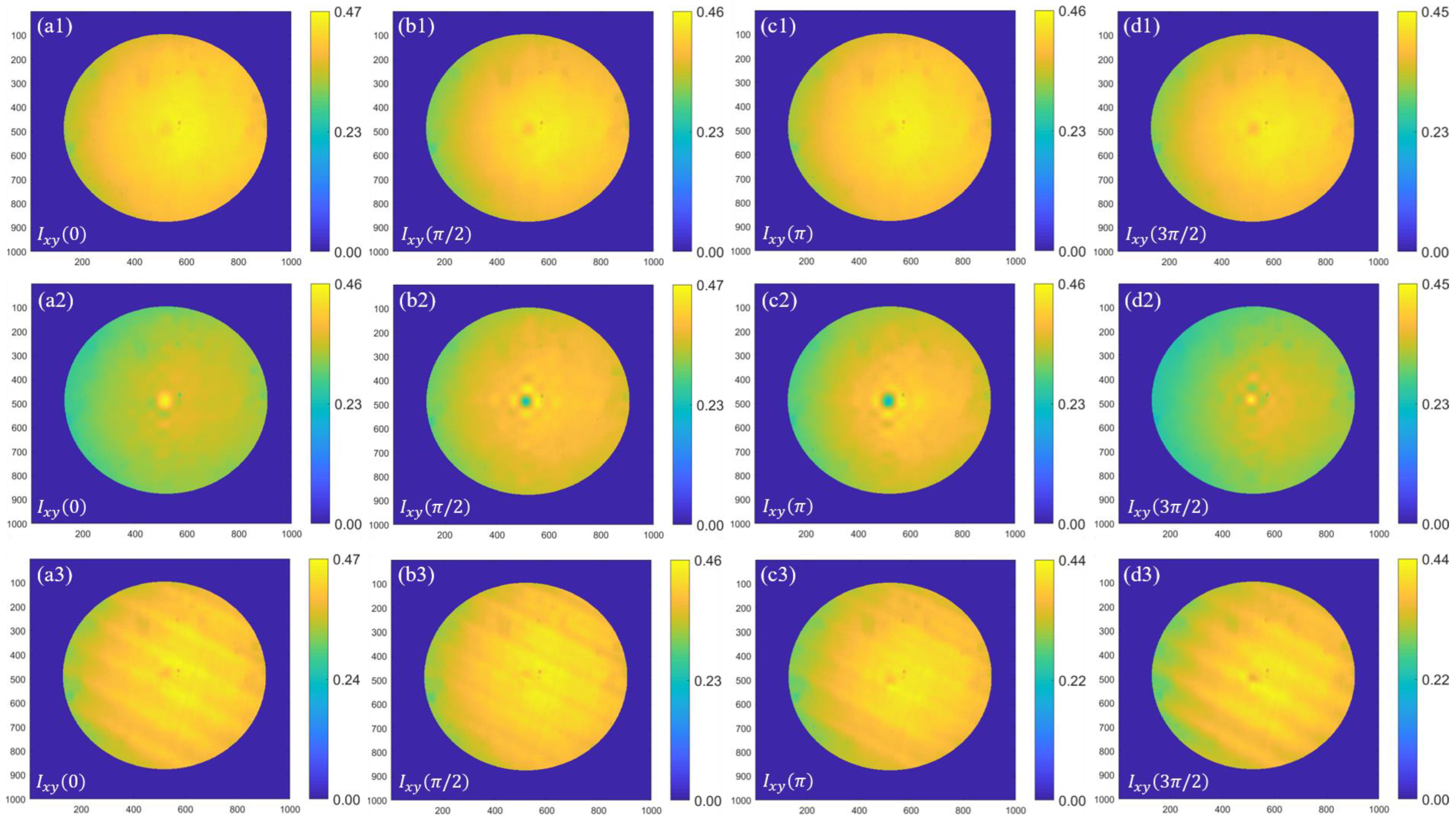
Figure 4 shows the recorded interferograms I x y 0 ,   I x y π / 2 ,   I x y π , and I x y 3 π / 2 with phase shifts 0 ,   π / 2 , π , and 3 π / 2 , respectively, corresponding to W x y ( α 1 ρ , α ρ ) for all three different polarization states of the source. Figure 4(a1–d1) show interferograms for an unpolarized LED source, Figure 4(a2–d2) show interferograms for a diagonally polarized polarizer P1, and Figure 4(a3–d3) show interferograms for an incoherent source with the DWD. These results clearly distinguish the difference between the recorded interferograms for varying polarization states of the incoherent source. The first row of Figure 4 presents results for an unpolarized LED source, revealing the absence of fringes in the captured interferograms. This occurs due to the lack of correlation between the orthogonally polarized field components of unpolarized light. The second row of Figure 4 shows results for a diagonally polarized light source. For the vectorial source, modulation in the central part is clearly visible in the interferograms for different phase shifts. The last row of Figure 4 shows the interferograms for an LED source with the DWD. The recorded interferogram shows a periodic pattern, and this spatially induced periodic pattern is due to the special properties of DWD, as discussed in Section 2. Similarly, we recorded the interferograms for W x x ( α 1 ρ , α ρ ) , W y x ( α 1 ρ , α ρ ) , and W y y ( α 1 ρ , α ρ ) for all three different sources, as previously discussed. After recording all four sets of interferograms for the four elements of the CSD matrix, we experimentally recovered the complex elements of the CSD matrix for different cases using Equations (26)–(28).
Figure 5 shows the results for amplitude (fringe visibility) and corresponding phase of the CSD matrix elements using Equations (26) and (27) for three sources, namely unpolarized LED, diagonally polarized LED light, and polarization tailored by the DWD. Figure 5(a1–d1) show the experimentally recorded amplitudes and Figure 5(a2–d2) show the corresponding phases for the CSD matrix elements of the unpolarized LED source. Figure 5(a1) shows the amplitude and Figure 5(a2) shows the corresponding phase for W x x α 1 ρ , α ρ . The observed results show the presence of fringe visibility for the unpolarized LED light because of the existing correlation between similar polarization components. In Figure 5(a1), the colormap illustrates that the maximum value of the correlation reaches 0.30. Figure 5(a2) shows the phase variation ranging from π to π .  Figure 5(b1) shows the amplitude, Figure 5(b2) shows the corresponding phase for W x y α 1 ρ , α ρ , Figure 5(c1) shows the amplitude, and Figure 5(c2) shows the corresponding phase for W y x α 1 ρ , α ρ . Negligible amplitudes of W x y α 1 ρ , α ρ and W y x α 1 ρ , α ρ emerge due to the lack of correlation among the orthogonal polarization components in the unpolarized LED source. Figure 5(d1) shows the amplitude and Figure 5(d2) shows the phase for W y y α 1 ρ , α ρ . The results reveal fringe visibility arising from the existing correlation among similar polarization components. The colormap in Figure 5(d1) shows that the maximum value of the fringe visibility approaches 0.31. The third and fourth rows in Figure 5 show the results for diagonally polarized light after filtering from the LED. Figure 5(a3–d3) show the amplitudes and Figure 5(a4–d4) show the corresponding phases of W x x ( α 1 ρ , α ρ ) , W x y ( α 1 ρ , α ρ ) , W y x α 1 ρ , α ρ , and W y y ( α 1 ρ , α ρ ) , respectively. The existence of fringes in all CSD matrix elements is attributed to the polarization filtering of the source by a linear polarizer oriented at 45° from its fast axis after the source. The maximum value for fringe visibility is around 0.31 and the phase map shows variation in the range of π to π . The fifth and sixth rows in Figure 5 show the experimental results for the LED source with a DWD. Figure 5(a5–d5) show the amplitudes and Figure 5(a6–d6) show the corresponding phases of W x x ( α 1 ρ , α ρ ) , W x y ( α 1 ρ , α ρ ) , W y x α 1 ρ , α ρ , and W y y ( α 1 ρ , α ρ ) , respectively. A periodic pattern is evident in the elements of the CSD matrix, attributed to the properties of DWD. Figure 5(a5,d5) show the amplitudes of W x x ( α 1 ρ , α ρ ) and W y y α 1 ρ , α ρ , respectively. Figure 5(a6,d6) show the corresponding phases of W x x ( α 1 ρ , α ρ ) and W y y α 1 ρ , α ρ , respectively. Figure 5(b5,c5) show the amplitudes of W x y ( α 1 ρ , α ρ ) and W y x α 1 ρ , α ρ , respectively. Similarly, the corresponding phases shown in Figure 5(b6,c6) for W x y ( α 1 ρ , α ρ ) and W y x α 1 ρ , α ρ show a regular periodic variation. Therefore, the influence of polarization appears in the elements of the CSD matrix.

5. Conclusions

In conclusion, we analyzed the coherence-polarization properties of different vector beams using experimental measurements of CSD matrix elements. We proposed employing a Sagnac shearing interferometer along with a four-step phase-shifting technique for measuring these CSD matrix elements. Three different sources were considered to highlight the role of polarization tailoring in the two-point correlation elements of the vector light, and the results are presented. The results demonstrate the influence of polarization on the coherence properties of light, as indicated by the spatial distributions of the retrieved CSD matrix elements in all three cases. Additionally, the method can be used to synthesize beams with conventional and exotic correlation structures.

Author Contributions

A.G.: Conceptualization, Investigation, Writing—manuscript, Methodology, Experimental Design. D.N.N.: Conceptualization, Writing—revision & editing, Supervision. C.S.N.: Writing—editing & revision. R.K.S.: Conceptualization, Formulation of research goals, Writing—revision & editing, Funding acquisition, Supervision. All authors have read and agreed to the published version of the manuscript.

Funding

This work is supported by the Board of Research in Nuclear Sciences (BRNS Grant No. 58/14/04/2021-BRNS/37092).

Institutional Review Board Statement

Not Applicable.

Informed Consent Statement

Not Applicable.

Data Availability Statement

Data underlying the results presented in this paper are not publicly available at this time but may be obtained from the authors upon reasonable request.

Acknowledgments

Akanksha Gautam would like to acknowledge support from DST-INSPIRE (IF180930), Rakesh Kumar Singh acknowledges fruitful discussion with Venu Gopal Achanta.

Conflicts of Interest

The authors have no conflicts of interest to disclose.

References

  1. Rubinsztein-Dunlop, H.; Forbes, A.; Berry, M.V.; Dennis, M.R.; Andrews, D.L.; Mansuripur, M.; Denz, C.; Alpmann, C.; Banzer, P.; Bauer, T.; et al. Roadmap on structured light. J. Opt. 2016, 19, 013001. [Google Scholar] [CrossRef]
  2. Forbes, A.; de Oliveira, M.; Dennis, M.R. Structured light. Nat. Photonics 2021, 15, 253–262. [Google Scholar] [CrossRef]
  3. Korotkova, O.; Gbur, G. Applications of Optical Coherence Theory. Prog. Opt. 2020, 65, 43–104. [Google Scholar]
  4. Forbes, A.; Dudley, A.; McLaren, M. Creation and detection of optical modes with spatial light modulators. Adv. Opt. Photonics 2016, 8, 200–227. [Google Scholar] [CrossRef]
  5. Ren, Y.X.; Lu, R.D.; Gong, L. Tailoring light with a digital micromirror device. Ann. Phys. 2015, 527, 447–470. [Google Scholar] [CrossRef]
  6. Yu, N.; Capasso, F. Flat optics with designer metasurfaces. Nat. Mater. 2014, 13, 139–150. [Google Scholar] [CrossRef] [PubMed]
  7. Keren-Zur, S.; Michaeli, L.; Suchowski, H.; Ellenbogen, T. Shaping light with nonlinear metasurfaces. Adv. Opt. Photonics 2018, 10, 309–353. [Google Scholar] [CrossRef]
  8. Rumand, A.; Cardano, F.; Piccirillo, B.; Marrucci, L. Q-plate technology: A progress review. J. Opt. Soc. Am. B 2019, 36, D70–D87. [Google Scholar]
  9. Forbes, A. Structured light from lasers. Laser Photonics Rev. 2019, 13, 1900140. [Google Scholar] [CrossRef]
  10. Andrews, L.C.; Phillips, R.L. Laser Beam Propagation through Random Media; SPIE: Bellingham, DC, USA, 2005. [Google Scholar]
  11. Goodman, J.W. Speckle Phenomena in Optics: Theory and Applications; Roberts and Company Publishers: Greenwood Village, CO, USA, 2007. [Google Scholar]
  12. Mandel, L.; Wolf, E. Optical Coherence and Quantum Optics; Cambridge University Press: Cambridge, UK, 1995. [Google Scholar]
  13. Chen, Y.; Wang, F.; Zhao, C.; Cai, Y. Experimental demonstration of a Laguerre-Gaussian correlated Schell-model vortex beam. Opt. Express 2014, 22, 5826–5838. [Google Scholar] [CrossRef] [PubMed]
  14. Xu, H.-F.; Zhou, Y.; Wu, H.-W.; Chen, H.-J.; Sheng, Z.-Q.; Qu, J. Focus shaping of the radially polarized Laguerre-Gaussian-correlated Schell-model vortex beams. Opt. Express 2018, 26, 20076–20088. [Google Scholar] [CrossRef] [PubMed]
  15. Wang, X.; Yao, M.; Qiu, Z.; Yi, X.; Liu, Z. Evolution properties of Bessel-Gaussian Schell-model beams in non-Kolmogorov turbulence. Opt. Express 2015, 23, 12508–12523. [Google Scholar] [CrossRef]
  16. Peng, X.; Lu, X.; Liu, X.; Zhao, C.; Lin, R.; Liu, L.; Cai, Y. Generation and propagation of a Hermite-Gaussian correlated Schell-model LG0l Beam. Appl. Sci. 2019, 9, 610. [Google Scholar] [CrossRef]
  17. Korotkova, O.; Sahin, S.; Shchepakina, E. Multi-Gaussian Schell-model beams. J. Opt. Soc. Am. A 2012, 29, 2159–2164. [Google Scholar] [CrossRef] [PubMed]
  18. Cai, Y.; Chen, Y.; Wang, F. Generation and propagation of partially coherent beams with nonconventional correlation functions: A review. J. Opt. Soc. Am. A 2014, 31, 2083–2096. [Google Scholar] [CrossRef] [PubMed]
  19. Cui, S.; Chen, Z.; Zhang, L.; Pu, J. Experimental generation of nonuniformly correlated partially coherent light beams. Opt. Lett. 2013, 38, 4821–4824. [Google Scholar] [CrossRef] [PubMed]
  20. Takeda, M.; Wang, W.; Duan, Z.; Miyamoto, Y. Coherence holography. Opt. Express 2005, 13, 9629–9635. [Google Scholar] [CrossRef]
  21. Naik, D.N.; Singh, R.K.; Ezawa, T.; Miyamoto, Y.; Takeda, M. Photon correlation holography. Opt. Express 2011, 19, 1408–1421. [Google Scholar] [CrossRef]
  22. Wang, F.; Liu, X.; Yuan, Y.; Cai, Y. Experimental generation of partially coherent beams with different complex degrees of coherence. Opt. Lett. 2013, 38, 1814–1816. [Google Scholar] [CrossRef]
  23. Santarsiero, M.; Martínez-Herrero, R.; Maluenda, D.; De Sande, J.C.; Piquero, G.; Gori, F. Partially coherent sources with circular coherence. Opt. Lett. 2017, 42, 1512–1515. [Google Scholar] [CrossRef]
  24. Singh, R.K.; Sharma, A.M.; Senthilkumaran, P. Vortex array embedded in a partially coherent beam. Opt. Lett. 2015, 40, 2751–2754. [Google Scholar] [CrossRef]
  25. Mei, Z.; Korotkova, O.; Zhao, D.; Mao, Y. Self-focusing vortex beams. Opt. Lett. 2021, 46, 2384–2387. [Google Scholar] [CrossRef]
  26. Wolf, E. Introduction to the Theory of Coherence and Polarization of Light; Cambridge University Press: Cambridge, UK, 2007. [Google Scholar]
  27. Wolf, E. Unified theory of coherence and polarization of random electromagnetic beams. Phys. Lett. A 2003, 312, 263–267. [Google Scholar] [CrossRef]
  28. Friberg, A.T.; Setälä, T. Electromagnetic theory of optical coherence (invited). J. Opt. Soc. Am. A 2016, 33, 2431–2442. [Google Scholar] [CrossRef]
  29. James, D.F.V. Changes of polarization of light beams on propagation in free space. J. Opt. Soc. Am. A 1994, 11, 1641–1643. [Google Scholar] [CrossRef]
  30. Agrawal, G.P.; Wolf, E. Propagation-induced polarization changes in partially coherent optical beams. J. Opt. Soc. Am. A 2000, 17, 2019–2023. [Google Scholar] [CrossRef] [PubMed]
  31. Brown, D.P.; Brown, T.G. Partially correlated azimuthal vortex illumination: Coherence and correlation measurements and effects in imaging. Opt. Express 2008, 16, 20418–20426. [Google Scholar] [CrossRef] [PubMed]
  32. Lerman, G.M.; Levy, U. Effect of radial polarization and apodization on spot size under tight focusing conditions. Opt. Express 2008, 16, 4567–4581. [Google Scholar] [CrossRef] [PubMed]
  33. Huang, L.; Guo, H.; Li, J.; Ling, L.; Feng, B.; Li, Z.Y. Optical trapping of gold nanoparticles by cylindrical vector beam. Opt. Lett. 2012, 37, 1694–1696. [Google Scholar] [CrossRef] [PubMed]
  34. Gataric, M.; Gordon, G.S.; Renna, F.; Ramos, A.G.; Alcolea, M.P.; Bohndiek, S.E. Reconstruction of optical vector-fields with applications in endoscopic imaging. IEEE Trans. Med. Imaging 2018, 38, 955–967. [Google Scholar] [CrossRef] [PubMed]
  35. Lee, K.G.; Kihm, H.W.; Kihm, J.E.; Choi, W.J.; Kim, H.; Ropers, C.; Park, D.J.; Yoon, Y.C.; Choi, S.B.; Woo, D.H.; et al. Vector field microscopic imaging of light. Nat. Photonics 2007, 1, 53–56. [Google Scholar] [CrossRef]
  36. Bautista, G.; Kauranen, M. Vector-field nonlinear microscopy of nanostructures. ACS Photonics 2016, 3, 1351–1370. [Google Scholar] [CrossRef]
  37. Ouyang, J.; Perrie, W.; Allegre, O.J.; Heil, T.; Jin, Y.; Fearon, E.; Eckford, D.; Edwardson, S.P.; Dearden, G. Tailored optical vector fields for ultrashort-pulse laser induced complex surface plasmon structuring. Opt. Express 2015, 23, 12562–12572. [Google Scholar] [CrossRef] [PubMed]
  38. Liu, L.; Huang, Y.; Chen, Y.; Guo, L.; Cai, Y. Orbital angular moment of an electromagnetic Gaussian Schell-model beam with a twist phase. Opt. Express 2015, 23, 30283–30296. [Google Scholar] [CrossRef]
  39. Korotkova, O.; Chen, X.; Setälä, T. Electromagnetic Schell-model beams with arbitrary complex correlation states. Opt. Lett. 2019, 44, 4945–4948. [Google Scholar] [CrossRef] [PubMed]
  40. Chen, Y.; Wang, F.; Liu, L.; Zhao, C.; Cai, Y.; Korotkova, O. Generation and propagation of a partially coherent vector beam with special correlation functions. Phys. Rev. A 2014, 89, 013801. [Google Scholar] [CrossRef]
  41. Singh, R.K.; Naik, D.N.; Itou, H.; Miyamoto, Y.; Takeda, M. Vectorial coherence holography. Opt. Express 2011, 19, 11558–11567. [Google Scholar] [CrossRef] [PubMed]
  42. Mishra, S.; Gautam, S.K.; Naik, D.N.; Chen, Z.; Pu, J.; Singh, R.K. Tailoring and analysis of vectorial coherence. J. Opt. 2018, 20, 125605. [Google Scholar] [CrossRef]
  43. Shirai, T.; Wolf, E. Coherence and polarization of electromagnetic beams modulated by random phase screens and their changes on propagation in free space. J. Opt. Soc. Am. A 2004, 21, 1907–1916. [Google Scholar] [CrossRef]
  44. Liu, Y.; Dong, Z.; Wang, F.; Cai, Y.; Chen, Y. Experimental synthesis of higher-order Poincaré sphere beam array with spatial coherence engineering. Appl. Phys. Lett. 2023, 122, 161106. [Google Scholar] [CrossRef]
  45. Chen, L.; Chen, Z.; Singh, R.K.; Pu, J. Imaging of polarimetric-phase object through scattering medium by phase shifting. Opt. Express 2020, 28, 8145–8155. [Google Scholar] [CrossRef]
  46. Kanseri, B.; Kandpal, H.C. Experimental determination of electric cross-spectral density matrix and generalized Stokes parameters for a laser beam. Opt. Lett. 2008, 33, 2410–2412. [Google Scholar] [CrossRef]
  47. Partanen, H.; Hoenders, B.J.; Friberg, A.T.; Setälä, T. Young’s interference experiment with electromagnetic narrowband light. J. Opt. Soc. Am. A 2018, 35, 1379–1384. [Google Scholar] [CrossRef]
  48. Lu, X.; Shao, Y.; Zhao, C.; Konijnenberg, S.; Zhu, X.; Tang, Y.; Cai, Y.; Urbach, H.P. Noniterative spatially partially coherent diffractive imaging using pinhole array mask. Adv. Photonics 2019, 1, 016005. [Google Scholar] [CrossRef]
  49. Turunen, J.; Halder, A.; Koivurova, M.; Setälä, T. Measurement of spatial coherence of light [Invited]. J. Opt. Soc. Am. A 2022, 39, C214–C239. [Google Scholar] [CrossRef]
  50. Hassinen, T.; Tervo, J.; Setälä, T.; Friberg, A.T. Hanbury Brown–Twiss effect with electromagnetic waves. Opt. Express 2011, 19, 15188–15195. [Google Scholar] [CrossRef] [PubMed]
  51. Singh, R.K.; Sharma, M.A. Recovery of complex valued objects from two-point intensity correlation measurement. Appl. Phys. Lett. 2014, 104, 111108. [Google Scholar] [CrossRef]
  52. Vinu, R.V.; Singh, R.K. Experimental determination of generalized Stokes parameters. Opt. Lett. 2015, 40, 1227–1230. [Google Scholar] [CrossRef] [PubMed]
  53. Yoneda, N.; Quan, X.; Matoba, O. Single-shot generalized Hanbury Brown–Twiss experiments using a polarization camera for target intensity reconstruction in scattering media. Opt. Lett. 2023, 48, 632–635. [Google Scholar] [CrossRef]
  54. Dong, Z.; Huang, Z.; Chen, Y.; Wang, F.; Cai, Y. Measuring complex correlation matrix of partially coherent vector light via a generalized Hanbury Brown–Twiss experiment. Opt. Express 2020, 28, 20634–20644. [Google Scholar] [CrossRef]
  55. Wang, Z.; Lu, X.; Huang, W.; Konijnenberg, A.P.; Zhang, H.; Zhao, C.; Cai, Y. Measuring the complete complex correlation matrix of a partially coherent vector beam via self-referencing holography. Appl. Phys. Lett. 2021, 119, 111101. [Google Scholar] [CrossRef]
  56. Gautam, A.; Athira, T.S.; Naik, D.N.; Singh, R.; Narayanamurthy, C.S.; Singh, R.K. Recording of incoherent vector holograms using elements of the spatial cross-spectral density matrix. Opt. Lasers Eng. 2023, 169, 107687. [Google Scholar] [CrossRef]
  57. Chandra, S.; Gautam, A.; Singh, R.K. Folded interferometer to measure coherence-polarization matrix. Opt. Lett. 2023, in press. [Google Scholar] [CrossRef]
  58. Tervo, J.; Turunen, J. Transverse and longitudinal periodicities in fields produced by polarization gratings. Opt. Commun. 2001, 190, 51–57. [Google Scholar] [CrossRef]
  59. De Sande, J.C.G.; Santarsiero, M.; Piquero, G.; Gori, F. Longitudinal polarization periodicity of unpolarized light passing through a double wedge depolarizer. Opt. Express 2012, 20, 27348–27360. [Google Scholar] [CrossRef] [PubMed]
  60. Singh, R.K.; Naik, D.N.; Itou, H.; Miyamoto, Y.; Takeda, M. Stokes holography. Opt. Lett. 2012, 37, 966–968. [Google Scholar] [CrossRef] [PubMed]
  61. Tervo, J. Azimuthal polarization and partial coherence. J. Opt. Soc. Am. A 2003, 20, 1974–1980. [Google Scholar] [CrossRef] [PubMed]
  62. Piquero, G.; Vargas-Balbuena, J. Non-uniformly polarized beams across their transverse profiles: An introductory study for undergraduate optics courses. Eur. J. Phys. 2004, 25, 793. [Google Scholar] [CrossRef]
  63. Beckley, A.M.; Brown, T.G.; Alonso, M.A. Full Poincaré beams. Opt. Express 2010, 18, 10777–10785. [Google Scholar] [CrossRef]
  64. Chandra, S.; Singh, R.; Singh, R.K. Poincare vector correlations to estimate polarization dynamics in the laser speckle. Phys. Scr. 2023, 98, 065504. [Google Scholar] [CrossRef]
  65. Korotkova, O.; Wolf, E. Changes in the state of polarization of a random electromagnetic beam on propagation. Opt. Commun. 2005, 246, 35–43. [Google Scholar] [CrossRef]
  66. Sarkar, T.; Chandra, S.; Singh, R.K. Phase recovery with intensity and polarization correlation. Prog. Opt. 2023, 68, 101–190. [Google Scholar]
  67. De Sande, J.C.G.; Piquero, G.; Santarsiero, M.; Gori, F. Partially coherent electromagnetic beams propagating through double-wedge depolarizers. J. Opt. 2014, 16, 035708. [Google Scholar] [CrossRef]
  68. Santarsiero, M.; De Sande, J.C.G.; Piquero, G.; Gori, F. Coherence–polarization properties of fields radiated from transversely periodic electromagnetic sources. J. Opt. 2013, 15, 055701. [Google Scholar] [CrossRef]
  69. Partanen, H.; Friberg, A.T.; Setälä, T.; Turunen, J. Spectral measurement of coherence Stokes parameters of random broadband light beams. Photonics Res. 2019, 7, 669–677. [Google Scholar] [CrossRef]
  70. Helen, S.S.; Kothiyal, M.P.; Sirohi, R.S. Achromatic phase shifting by a rotating polarizer. Opt. Commun. 1998, 154, 249–254. [Google Scholar] [CrossRef]
  71. Gori, F.; Ramírez-Sánchez, V.; Santarsiero, M.; Shirai, T. On genuine cross-spectral density matrices. J. Opt. A Pure Appl. Opt. 2009, 11, 085706. [Google Scholar] [CrossRef]
  72. Singh, R.K.; Naik, D.N.; Itou, H.; Brundabanam, M.M.; Miyamoto, Y.; Takeda, M. Vectorial van Cittert–Zernike theorem based on spatial averaging: Experimental demonstrations. Opt. Lett. 2013, 38, 4809–4812. [Google Scholar] [CrossRef] [PubMed]
  73. Gerrard, A.; Burch, J.M. Introduction to Matrix Methods in Optics; Courier Corporation: Chelmsford, MA, USA, 1994. [Google Scholar]
  74. Roy, M.; Svahn, P.; Cherel, L.; Sheppard, C.J.R. Geometric phase-shifting for low-coherence interference microscopy. Opt. Lasers Eng. 2002, 37, 631–641. [Google Scholar] [CrossRef]
Figure 1. Schematic representation of measurement of two-point correlation in the far-field from an incoherent source, L: Lens.
Photonics 11 00142 g001
Figure 2. Schematic illustration of DWD.
Photonics 11 00142 g002
Figure 3. Experimental setup of square Sagnac radial shearing interferometer: P: polarizer, DWD: double-wedge depolarizer, L: lens, PBS: polarization beam splitter, M: mirror, HWP: half-wave plate, QWP: quarter-wave plate, CCD: charge-coupled device.
Photonics 11 00142 g003
Figure 4. Four experimentally recorded interferograms for phase shifts 0, π/2, π, and 3π/2 for W x y α 1 u ,   α u : (a1d1) unpolarized LED, (a2d2) diagonally polarized polarizer, and (a3d3) DWD.
Photonics 11 00142 g004
Figure 5. Elements of CSD matrix for three different cases: (a1d2) unpolarized LED, (a3d4) diagonally polarized polarizer, and (a5d6) DWD. In different sets, the absolute values of the CSD matrix elements i.e., fringe visibility values are represented using g m n ρ 1 ,   ρ 2 , and the corresponding phases using ϕ m n ρ 1 ,   ρ 2 .
Photonics 11 00142 g005
Disclaimer/Publisher’s Note: The statements, opinions and data contained in all publications are solely those of the individual author(s) and contributor(s) and not of MDPI and/or the editor(s). MDPI and/or the editor(s) disclaim responsibility for any injury to people or property resulting from any ideas, methods, instructions or products referred to in the content.