Article

Simulation Study on Flow Field and Total Noise Characteristics of Segmented Ducted Fan for Small UAVs


by
Xulin Wang
1,* and
Jianwei Ma
2
1
School of General Aviation and Flight, Nanjing University of Aeronautics and Astronautics, Liyang 213300, China
2
School of Mechanical Engineering, Dalian University of Technology, Dalian 116024, China
*
Author to whom correspondence should be addressed.
Vehicles 2026, 8(7), 165; https://doi.org/10.3390/vehicles8070165
Submission received: 9 April 2026 / Revised: 10 July 2026 / Accepted: 13 July 2026 / Published: 15 July 2026

Abstract

Small unmanned aerial vehicles (UAVs) are widely used in civil and military fields, and their noise problem has always been the industry’s focus. Compared with a traditional propeller fan, a ducted fan offers higher aerodynamic efficiency, lower aerodynamic noise, and greater safety. It has become the key power component of small UAVs. However, due to the rigid restriction on tip clearance, the traditional integral ducted fan is prone to generating a tip leakage vortex, which produces high-intensity aerodynamic noise and significantly reduces propulsion efficiency. To address the above key problem restricting the quiet flight of small UAVs, this paper designs a segmented ducted fan (SDF). It preliminarily explores the influence of the segmented clearance on the fan’s flow field structure and acoustic radiation characteristics. Specifically, the k-ω SST (shear stress transport) turbulence model and the broadband noise source model were used to establish a computational fluid dynamics model, and the effects of fan speed (20,000–40,000 rpm) and duct spacing (0–20 mm) on its aeroacoustic characteristics were systematically studied. The results showed that the SDF’s acoustic power level maximum (APLmax) was significantly higher than that of the traditional integral structure, especially at high speed. At 40,000 rpm, increasing the duct spacing to 20 mm resulted in a sudden increase in APLmax to 194.5 dB, 61.3 dB higher than that of the integral type. Its essence was derived from the three-stage chain amplification mechanism: (1) strong tip leakage vortex induced by geometric clearance; (2) broadband noise caused by vortex impacting the duct wall; (3) resonant coupling of leakage vortex harmonic frequency and duct cavity standing wave. Based on this, a collaborative noise reduction path was proposed: compressing the spacing to ≤10 mm to suppress the intensity of leakage vortex, designing the periodicity of failure vortex combined with the serrated blade tip/inner wall rubber strip, and blocking the acoustic cavity resonance with non-uniform wall stiffness or 8–10 kHz Helmholtz resonator, providing a solution for the low-noise design of UAV propulsion system. Unfortunately, our study cannot currently resolve transient characteristics; only time-averaged velocity/pressure flow-field contours and total acoustic power distribution are obtained for qualitative analysis of macroscopic noise variation laws and flow-sound correlation.

1. Introduction

With the rapid advancement of unmanned aerial vehicle (UAV) technology, small UAVs have been extensively employed in civilian and military applications, including logistics distribution, environmental monitoring, post-disaster rescue, aerial photography, low-altitude surveillance, and target strike, due to their excellent maneuverability and cost-effectiveness [1]. However, the noise issue of UAVs remains unresolved, which not only disturbs daily living environments but also impairs stealth performance in special missions, severely restricting the application of UAVs in quiet, concealed scenarios [2]. Compared with conventional propeller fans, ducted fans offer higher aerodynamic efficiency, lower aerodynamic noise, and greater safety, making them the core propulsion component for small UAVs [1,2]. Further, a double-ducted fan (DDF) uses a secondary shroud to mitigate the momentum deficit at the fan rotor inlet caused by lip separation during edge-wise flight [3]. This design significantly improves the thrust of the ducted fan.
In recent years, extensive research has been conducted on the aerodynamic and aeroacoustic characteristics of ducted fan systems, resulting in remarkable advances in flow mechanisms, noise prediction, and control methods. Luo et al. [4,5,6] successively used the unsteady Reynolds-averaged Navier–Stokes (RANS) method and sliding-grid and dynamic-grid technology to explore the influence of wind field, ground effect, and ground and ceiling effect on ducted fan thrust and flow field structure in the process of hovering and lifting in confined space, and defined the variation law of rotor and ducted thrust under different external environments, the related flow mechanism, and the influence range of proximity effect. Hirono et al. [7] performed aerodynamic and aeroacoustic optimization on electric ducted fans and determined the optimal flow coefficient range through numerical and experimental validation. Yokoyama et al. [8] applied plasma actuators for flow and sound-field control, effectively suppressing duct acoustic resonance under low- and medium-flow conditions. Ghosh et al. [9] used the Delayed Detached-eddy Simulation (DDES) method to study the vortex structures and acoustic superposition of parallel axial-flow fans. Dietrich et al. [10] developed a fast turbulence reconstruction method to achieve efficient noise prediction under realistic turbulent inlet conditions. Li et al. [11] proposed a machine learning-assisted low-order model for rapid prediction of broadband rotor-stator interaction noise. Pouryoussefi et al. [12] experimentally confirmed that boundary layer ingestion improves aerodynamic performance and delays stall. Suzuki [13] combined improved DDES and linear stability analysis to uncover the correlation between spiral flow instabilities and broadband noise. Blázquez-Navarro et al. [14] validated the linearized Navier–Stokes-based broadband noise prediction method and quantitatively demonstrated that increasing fan-OGV (Outlet-Guide-Van) axial clearance tends to intensify noise. The above studies have systematically clarified the generation and propagation mechanisms of ducted fan noise, laying a solid theoretical foundation for low-noise design.
Nevertheless, most existing studies focus on conventional integral ducted fans with one outer duct [4,5,6,7,8]. Limited by fixed tip clearance, integral ducted fans easily generate strong tip leakage vortices, which produce high-level aerodynamic noise and significantly reduce propulsion efficiency, forming a major bottleneck for quiet small UAVs [9,10,11,12,13,14]. Currently, the aeroacoustic performance and noise-reduction mechanisms of a segmented ducted fan (SDF, which is a DDF) with split outer ducts remain poorly understood, hindering the development of advanced low-noise ducted fan technology [3].
To tackle the above critical issues, this paper designs the SDF and establishes a computational fluid dynamics (CFD) model using the k-ω SST (shear stress transport) turbulence model and the broadband noise source model. The influences of rotational speed and duct spacing on aeroacoustic characteristics are systematically investigated. The novelty of this work lies in revealing the three-stage chain noise amplification mechanism and the aeroacoustic performance laws of SDF, and in proposing a collaborative noise reduction strategy. The results provide a practical solution for the low-noise design of UAV propulsion systems. It should be noted that the core of this basic research is to explore the influence of the law of duct spacing and rotational speed on the aeroacoustic performance of SDF and to reveal the macroscopic noise-generation mechanism. At this stage, we primarily use numerical simulation to conduct theoretical exploration.

2. Basic Theory of Aeroacoustic Characteristics of the Ducted Fan

2.1. Working Principle and Governing Equation

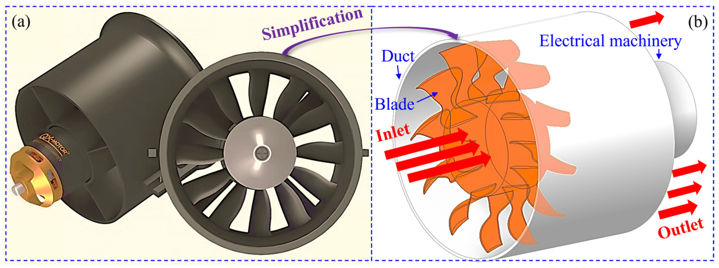
The ducted fan mainly comprises blades, duct, and motor (as shown in Figure 1). The duct serves to guide airflow, improve fan efficiency, reduce eddy-current losses at the blade tip, and reduce noise generation. Its core advantages are a compact structure and high thrust density, making it suitable for lightweight, low-noise small UAVs [1]. Its working principle is that blade rotation drives the surrounding airflow to generate thrust, and its duct guides airflow, reducing turbulence and energy loss [15]. The thrust F generated by the fan can be expressed as [12]:
F = m ˙ V O u t l e t V I n l e t
where is the air mass flow, and VOutlet and VInlet are the air velocities at the outlet and inlet of the duct, respectively. According to Formula (1), the duct design aims to make the VOutlet significantly larger than the VInlet to generate effective thrust.
The governing equations to be solved include the continuity equation (Formula (2)) and the momentum conservation equation (Formula (3)). To simplify the calculation, the fluid is regarded as an incompressible fluid, so the governing equation is [16,17,18]:
u x + v y + w z = 0
( ρ u ) t + div ( ρ u u ) = div ( μ grad u ) p x + F x ( ρ v ) t + div ( ρ v u ) = div ( μ grad v ) p y + F y ( ρ w ) t + div ( ρ w u ) = div ( μ grad w ) p z + F z
where ρ is the fluid density, μ is the dynamic viscosity, p is the fluid pressure, t is the time, and u, v, and w are the velocity components of the fluid in the x, y, and z directions, Fx, Fy, and Fz are the forces of the fluid in the x, y, and z directions, div is the divergence operator, and grad is the gradient operator.
In addition, SST is adopted as the turbulence model, which has the following advantages: (1) using the k-ω model (k is the turbulent kinetic energy and ω is the specific dissipation rate) in the boundary layer near the wall can give full play to the benefits of the k-ω model in small dissipation and good convergence of turbulence near the wall; (2) using the k-ω model in the far-field region has high computational efficiency and better adaptability to complex flow fields; and (3) the model is universal. The transport equation can be expressed as [18]:
The turbulent kinetic energy equation is:
t ( ρ k ) + x i ( ρ k u i ) = x i ( Γ k k x j ) + G k Y k + S k
The dissipation rate equation is:
t ( ρ ω ) + x i ( ρ ω u i ) = x i ( Γ ω ω x j ) + G ω Y ω + D ω + S ω
where Gk and Gω are the production terms of k and ω caused by the average velocity gradient, respectively. Γk and Γω are the effective diffusion terms of k and ω; ui is the velocity component, Yk and Yω are the divergent terms of k and ω; Dω is the orthogonal divergent term; and Sk and Sω are custom source items.
Subsequently, Formulas (2)–(5) will be solved using the CFD method to obtain the pressure and velocity distributions in the ducted fan flow field under different working conditions and to reveal the noise-generation mechanism of the SDF.

2.2. Noise Generation Mechanism of the Integral Ducted Fan

The noise of a ducted fan mainly comes from aerodynamic sources, including noise generated by the interaction between the blade and the air (such as vortex noise caused by turbulent flow), as well as additional noise from airflow obstruction, interference, or acceleration due to the ducted structure. When analyzing its acoustic characteristics, we should start with the mechanisms that generate aerodynamic noise (such as turbulence, blade passing frequency, and the gap effect) and the acoustic parameters (such as sound pressure level and acoustic power level). Among them, aerodynamic noise is mainly composed of broadband noise generated by turbulence around the blade and discrete noise caused by the interaction between the blade and the inner wall gap of the duct [19,20]. According to the classical aeroacoustic theory, the relationship between the total sound power W generated by the blade and the rotating speed N and the blade length R can be approximately expressed as [21,22,23]:
W N R 6
Mechanical noise is also a source of ducted fan noise. It comes from the vibration of the motor, bearing, and other components. Although the energy proportion is small, it cannot be ignored under specific working conditions. It produces radiated sound via structural transmission, which is significant at low speeds or when static. The noise frequency characteristic of a ducted fan is usually closely related to rotating speed N, blade number B, and harmonic order i, and its blade passing frequency fN can be expressed as [17]:
f N = N B i 60

2.3. Evaluation Parameters of Ducted Fan Noise Level

In the acoustic simulation and analysis of a ducted fan, acoustic parameters serve as the basis for evaluating and controlling noise levels. Commonly used acoustic parameters include sound pressure and power levels. The sound pressure level Lp reflects the strength of the sound wave when it propagates in space, which is defined as [24,25]:
L p = 20 lg p s p 0
where ps is the sound pressure (the change in pressure relative to static pressure caused by a sound wave propagating in a medium) and p0 is the reference sound pressure, usually 2 × 10⁻⁵ Pa.
Acoustic power level (APL) is the total sound energy radiated by the sound source per unit time, which is the inherent characteristic of the sound source, and its calculation formula is [26]:
APL L p + 10 lg S S 0
where S is the area of the measuring surface, and S0 is equal to 1 m2.
According to Formula (9), the APL quantifies the sound energy radiated by the source. Its value is not affected by the measurement location and environment, and can be directly related to aerodynamic parameters (such as speed and flow). Therefore, it is suitable for quantitative comparison of the aerodynamic and acoustic characteristics of ducted fans under different working conditions (such as evaluating the noise-reduction effect before and after optimization).

3. Numerical Simulation of Aerodynamic Noise of Ducted Fan

Referring to Section 2.1 and Section 2.2, the k-ω SST turbulence model (a steady-state RANS) is used to effectively capture the turbulent characteristics in complex flows, and a broadband noise source model is used to compute the vortex noise of the ducted fan. The research positioning and engineering objectives of this study determine the selection of a steady-state CFD and broadband noise source model. This work focuses on the comparative analysis of the overall acoustic power level and macroscopic flow-field characteristics of SDF at different rotational speeds and duct spacings, as well as a summary of the macroscopic chain noise amplification law. According to the classic aeroacoustic research and the application characteristics of the broadband noise source model, this model, based on steady-state RANS simulation, takes turbulent statistical characteristics as the core evaluation index, which is widely applied in the early design screening, parametric comparison, and overall noise level evaluation of turbomachinery such as ducted fans. It can efficiently capture the distribution of noise sources and the variation rule of the total acoustic power, fully meeting the research demands of this paper for macroscopic parametric analysis [27].
As stated above, the steady-state RANS and broadband noise source model adopted in this paper cannot capture unsteady physical quantities. The flow field nephograms (velocity field, pressure field) and acoustic power distribution nephograms obtained can only reflect the time-averaged intensity change in the tip leakage vortex, the average impact effect of the vortex on the duct wall, and the spatial distribution of total acoustic energy. This paper focuses on macroscopic parametric comparison and the analysis of overall noise-level rules.
In addition, using the multiple reference coordinate system method, the rotating domain surrounds the rotating part, and the stationary domain surrounds the stationary part. The connection between the two is realized through two non-overlapping surfaces: the interface. The flow field in the stationary domain is solved in the inertial coordinate system. In contrast, the flow field in the rotating domain is solved in the rotating coordinate system, and the rotating coordinate system’s rotating speed is set to simulate the fan speed.

3.1. SDF and Boundary Condition Setting

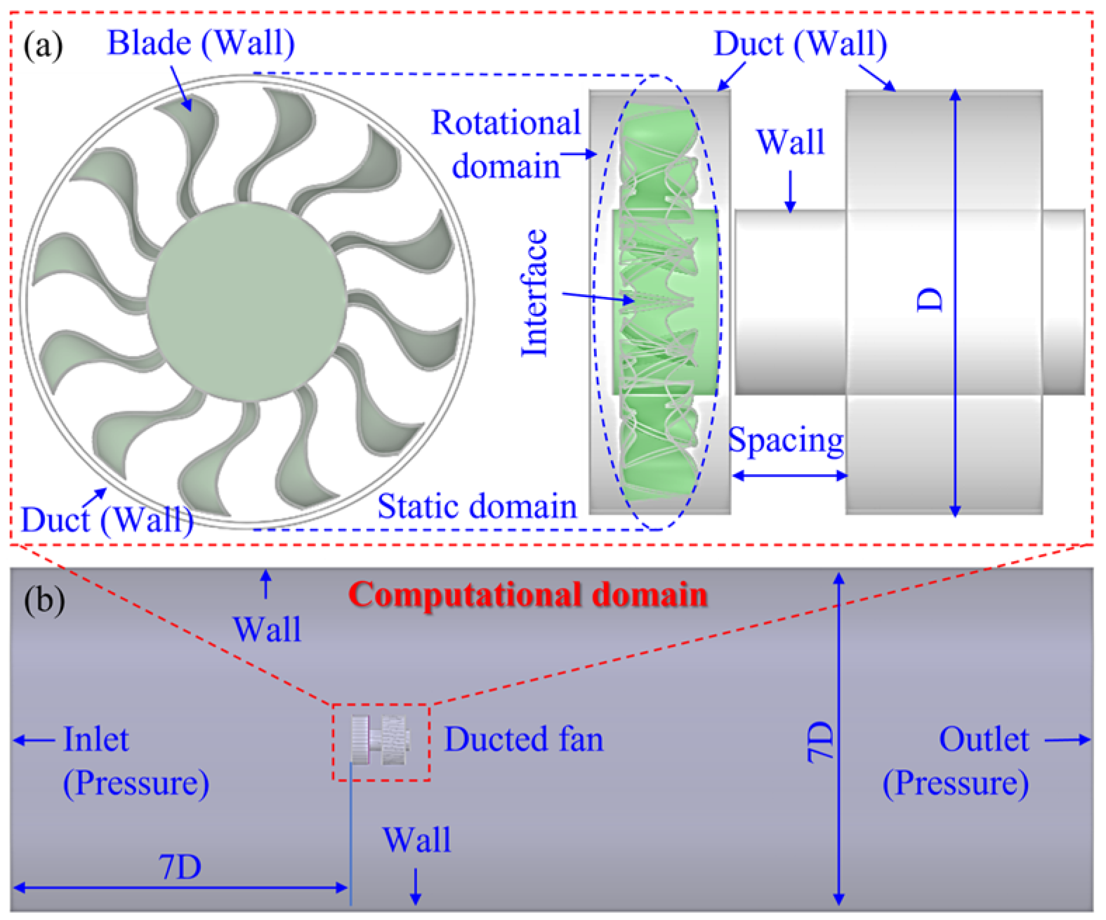
This study uses an SDF as the research object. The prototype model is properly simplified, retaining the core structural characteristics while following the conventional CFD simulation simplification principles for ducted fans. The core design parameters, such as blade number, chord length, twist angle, duct inner diameter, and tip clearance, are listed in Table 1 and fully define the main geometric characteristics of the research model, meeting the requirements of the parametric simulation analysis in this paper. Parameters of the integrated ducted fan are shown in Table 1. Based on the key parameters and the main geometric factor, after retaining the key structure, the physical object is geometrically simplified, and the geometric model of the integral ducted fan is established, as shown in Figure 1b. On this basis, assuming the duct length remains unchanged, the duct is divided into two parts (total length 58 mm, with 24 mm in the rotating area). The geometric model of the SDF is established by adjusting the duct spacing, as shown in Figure 2a. The geometric model and boundary conditions of the calculation domain are shown in Figure 2b. The calculation domain should be long enough to capture the information of the wake field passing through the ducted fan, set to 22D (D is the outer diameter of the ducted fan, 73 mm), and its diameter set to 7D, to avoid mutual interference of the boundary layer during the simulation process. In addition, the inlet and outlet of the calculation domain are a pressure inlet and a pressure outlet, respectively. The fan blade (mark the propeller in the rotating domain as a rotating part and specify its rotation direction to distinguish the relative motion relationship between the stationary domain and the rotating part), the duct, the motor, and the boundary outside the calculation domain are set as wall boundary conditions.

3.2. Grid Generation Strategy and Simulation Settings of the Computing Domain

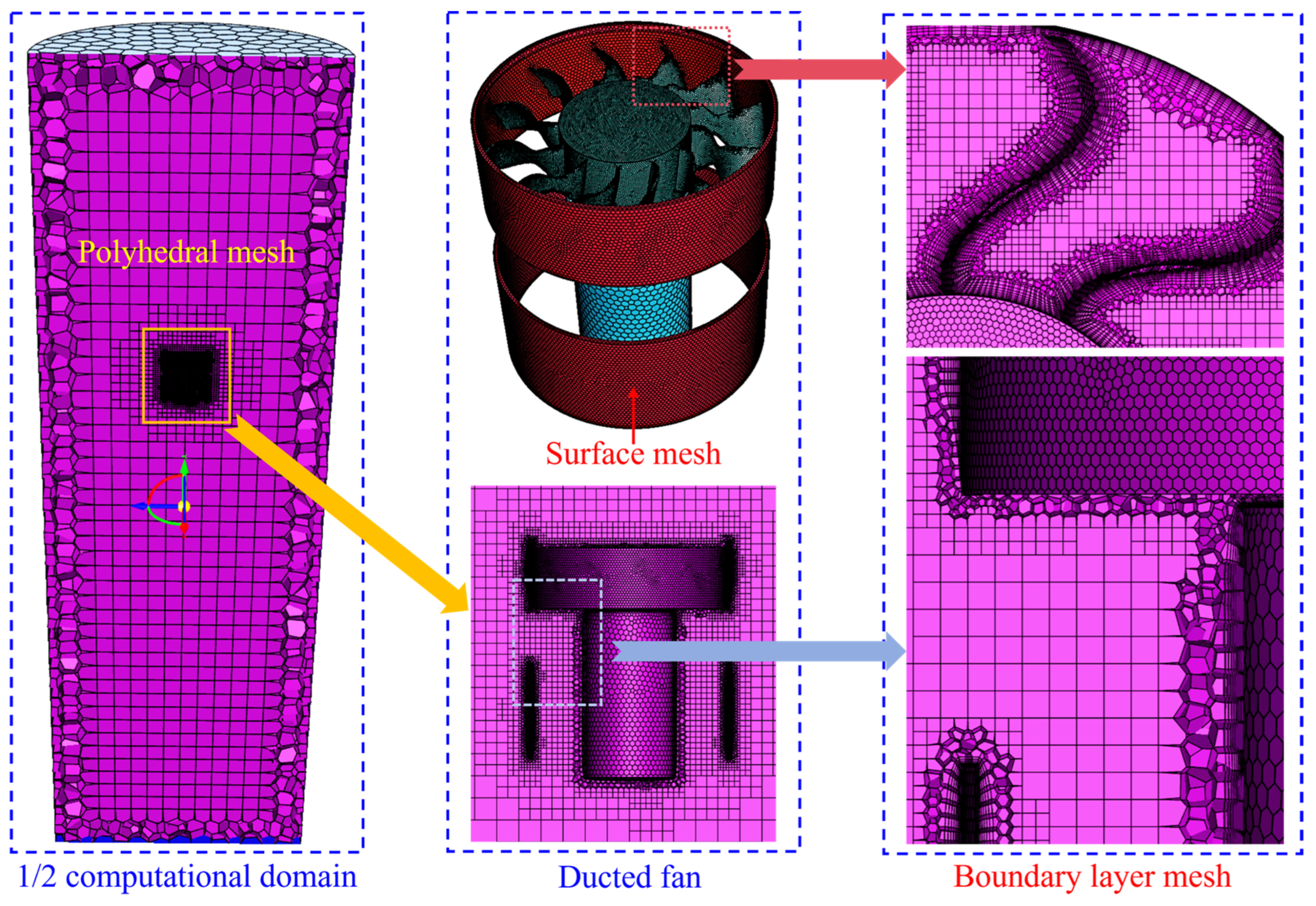
High-quality polyhedral and boundary-layer meshing are made by Fluent Meshing in Fluent. Different mesh densities across regions must be set to ensure high accuracy in the results. The key size parameters and quality indicators of the computational domain grid are shown in Table 2. In the rotating domain where the ducted fan blade is located, the grid spacing is set to 0.5–0.7 mm to accurately capture the blade boundary layer and vortex characteristics. Considering calculation efficiency, the grid size is set to 1–1.2 mm for the area where the duct and motor are located, and to 1.5 mm elsewhere. In addition, orthogonality, distortion, and stretching ratio are used to evaluate the quality of grid elements. Table 2 shows that the orthogonality of the grid element is greater than 0.7, the skewness is less than 0.3, and the draw ratio is controlled within 5 to ensure numerical stability. The schematic diagram of the divided computational domain grid is shown in Figure 3. For the grid around the blades, ducts, and motors, a multi-layer boundary-layer grid (15 layers) is used. The dimensionless grid height y+ < 1 of the first layer in the boundary layer is set to meet the turbulence model’s requirements for boundary-layer analysis, ensuring the acquisition of high-precision acoustic features. The grid-division strategy for the computational domain above lays the foundation for the reliability calculation of the ducted fan’s aerodynamic and acoustic characteristics.
Table 3 shows the numerical simulation parameters. According to the selected no-load speed of the motor up to 40,000 rpm, set the fan speed to 20,000–40,000 rpm. In the follow-up, the influence of fan speed on the ducted fan’s aerodynamic noise is primarily considered, and the influence of the incoming flow is not, so the inlet pressure is set to 0. In addition, as shown in Section 2.1, to simplify the calculation, the fluid is treated as incompressible, so the air parameters are set to constants (density = 1.225 kg/m3, dynamic viscosity = 1.7894 × 10⁻⁵ Pa·s). Based on Section 2.2, the k-ω SST turbulence model is used to effectively capture turbulent characteristics in complex flows, and the broadband noise source model is used to simulate vortex noise from the ducted fan. Finally, the Presto solver in Fluent is used for simulation calculations.

3.3. Reliability Verification of the CFD Model

In the acoustic simulation of a ducted fan for a small UAV, verifying grid independence is key to ensuring the reliability of the calculation results. The grid density around the duct fan, the inner and outer walls of the duct, and the motor is controlled uniformly (grid size regulation). Under a rotating speed of 20,000 rpm, the influence of the integral and segmented grid density on APLmax (APL maximum) is obtained, as shown in Table 4. Table 4 shows that the APLmax of the integral and SDF (ducted spacing of 10 mm and 20 mm, respectively) decreases slightly with decreasing grid density. The results show that the mesh density is reduced by about 30%, while the APLmax of the integral ducted fan is reduced by only about 1.5%. For SDF with 10 mm spacing, the grid density decreases by about 13.4%, while APLmax decreases by only about 1.1%. The grid density is reduced by about 20%, and the APLmax of ducted fans with 20 mm spacing is only reduced by about 0.8%. To sum up, the grid scheme adopted in this paper has little effect on APLmax, with no more than 1.5%, thereby preliminarily verifying the reliability of the CFD model and enabling the reliability calculation of the aerodynamic and acoustic characteristics of the ducted fans.

4. Results and Discussion

4.1. Influence of Fan Speed on the Aeroacoustic Performance of an Integral Ducted Fan

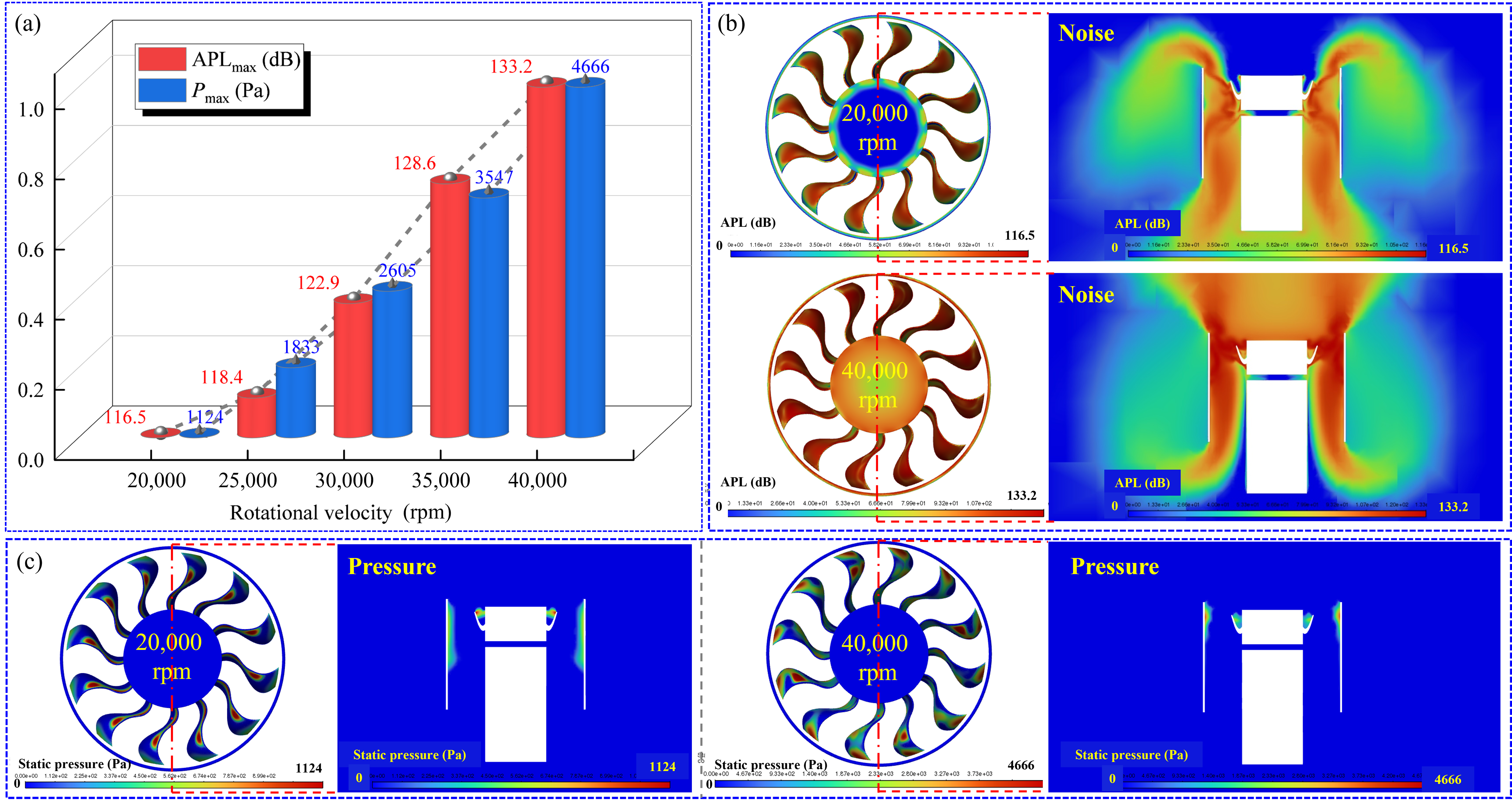
This part takes the integral ducted fan as the research object. It aims to further verify the reliability of the numerical simulation method by combining it with the content of the second part, to ensure the subsequent reliable analysis of the aerodynamic noise law of the SDF. As shown in Figure 4a, increasing the ducted fan speed has a significant positive impact on the noise level (APLmax), with a clear monotonic increase. Specifically, when the fan speed increases from 20,000 rpm to 40,000 rpm, the APLmax rises from 116.5 dB to 133.2 dB. In this process, the increase in APLmax is non-linear and uniform, but shows an acceleration effect (as described by Formula (6)). Specifically, APLmax was 116.5 dB at 20,000 rpm, and increased to 118.4 dB (+1.9 dB) at 25,000 rpm. However, APLmax jumped from 128.6 dB to 133.2 dB (+4.6 dB) from 35,000 rpm to 40,000 rpm, indicating that the contribution of the increase in per-unit speed to the improvement in noise was significantly greater at higher speeds. Overall, APLmax increased by 14.3% (relative to APLmax at 20,000 rpm), which reflects the inherent laws of machinery and fluid dynamics during fan operation, that is, the increase in rotating speed leads to the rise in blade rotating frequency and tip speed (following Formula (7)), which directly aggravates the disturbance of air, and thus enlarges the noise energy exponentially (following Formula (6)). This trend highlights that in the design of high-speed fans, speed control, as a key variable in noise management, must balance performance requirements and the impact on the acoustic environment. The specific mechanism for noise generation is as follows.
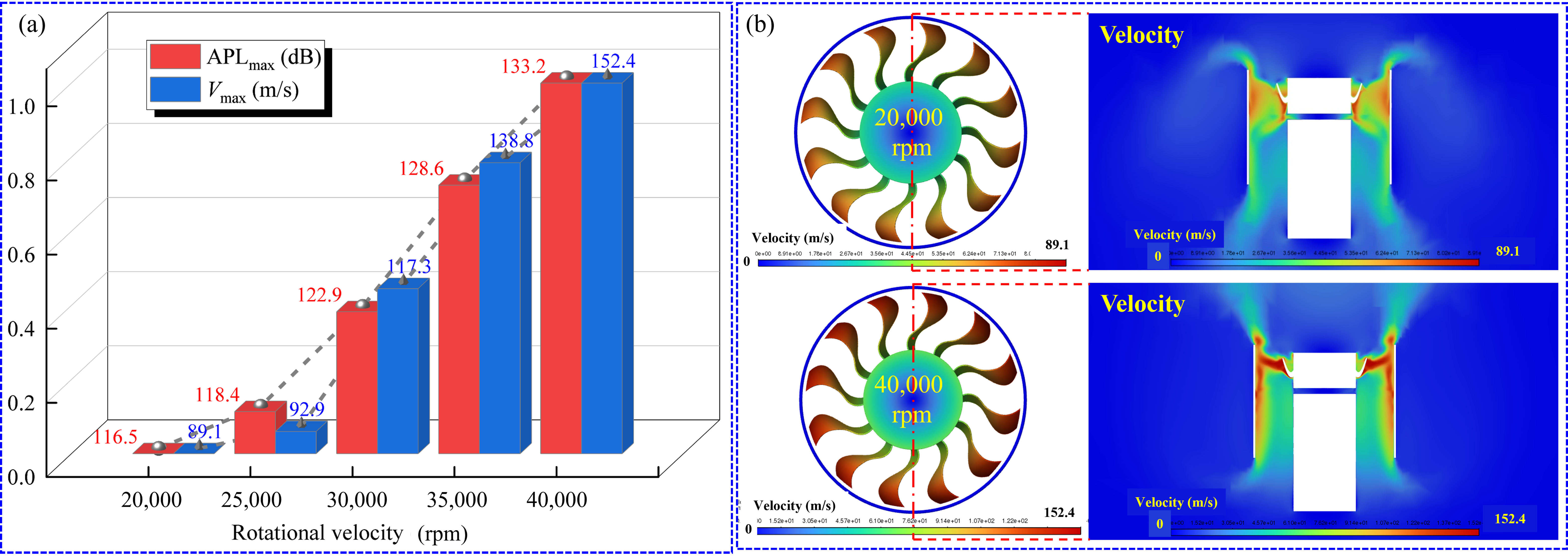
Increasing the ducted fan speed not only increases the noise but also synchronously enhances the maximum pressure (Pmax) and the maximum velocity (Vmax) of the flow field, which together drive the noise-generating mechanism. As shown in Figure 4a, Pmax rises from 1124 Pa at 20,000 rpm to 4666 Pa at 40,000 rpm; Figure 5a shows that Vmax rises from 89.1 m/s at 20,000 rpm to 152.4 m/s at 40,000 rpm. Pmax and Vmax showed an upward trend similar to APLmax with speed, indicating that increased speed exacerbated the dynamic pressure and flow velocity. According to the comparison of velocity nephogram in Figure 5b under the conditions of 20,000 rpm and 40,000 rpm, the main reason for the noise mechanism is that at 20,000 rpm, the velocity nephogram (blue background) shows that the velocity distribution is uniform and the gradient is gentle (the velocity around the white fan structure is stable). At this time, the pressure fluctuation is slight (Figure 4c), and the noise is low (about 116.5 dB). At 40,000 rpm, the velocity nephogram shows that the high-speed area (color area) is significantly expanded and the intensity is higher (Figure 5b shows that the high-speed area is concentrated at the blade tip), while the corresponding effect of the pressure nephogram shows that the local high-pressure points increase (Figure 4c), which leads to flow separation, vortex shedding and a sharp increase in turbulence intensity, causing broadband turbulence noise and discrete noise (it can be seen from Formula (7) that the blade passing frequency increases) [28]. The noise generation mechanism is essentially the amplification of pressure fluctuations induced by a velocity gradient; that is, the collision frequency and energy of gas molecules increase at high speeds, and the pressure fluctuations propagate through sound waves. The cloud image visually shows the correlation between the high-velocity region and the high-noise region (as shown in Figure 4b and Figure 5b, the high-speed region of the 40,000 rpm cloud image is larger, corresponding to 133.2 dB noise), indicating that the noise law conforms to the classical aerodynamic noise theory (following Formula (6)) [13]. Therefore, the core mechanism of ducted fan noise is the enhancement of hydrodynamic instability. The increase in rotation speed directly intensifies the noise source by amplifying the flow speed and the pressure gradient.
In conclusion, the above research results verify the reliability of the aeroacoustic numerical simulation method, which can be used to qualitatively analyze the aerodynamic noise characteristics and noise generation mechanism of the SDF.

4.2. Effect of Spacing on the Aeroacoustic Performance of the SDF

Table 5 shows the influence of duct spacing on the acoustic performance of duct fans (the integral duct fan is used as the reference, with a duct spacing of 0 mm). The results show that the sensitivity of duct fan noise to spacing is highly dependent on rotating speed, with a weak (+5.7 dB) effect at low rotation speed and an exponential increase (+61.3 dB) at high rotation speed. Therefore, the SDF design provides no additional noise reduction beyond the integral ducted fan. Next, we will combine the noise nephogram, pressure nephogram, and velocity nephogram of the influence of the duct spacing (0 mm, 10 mm, 20 mm) on the ducted fan at different speeds (20,000 rpm, 40,000 rpm), discuss and analyze the causes of the results in Table 5 in detail, and reveal the noise generation mechanism of the SDF.

4.2.1. Analysis of the Physical Mechanism of the Flow Field–Sound Field Correlation

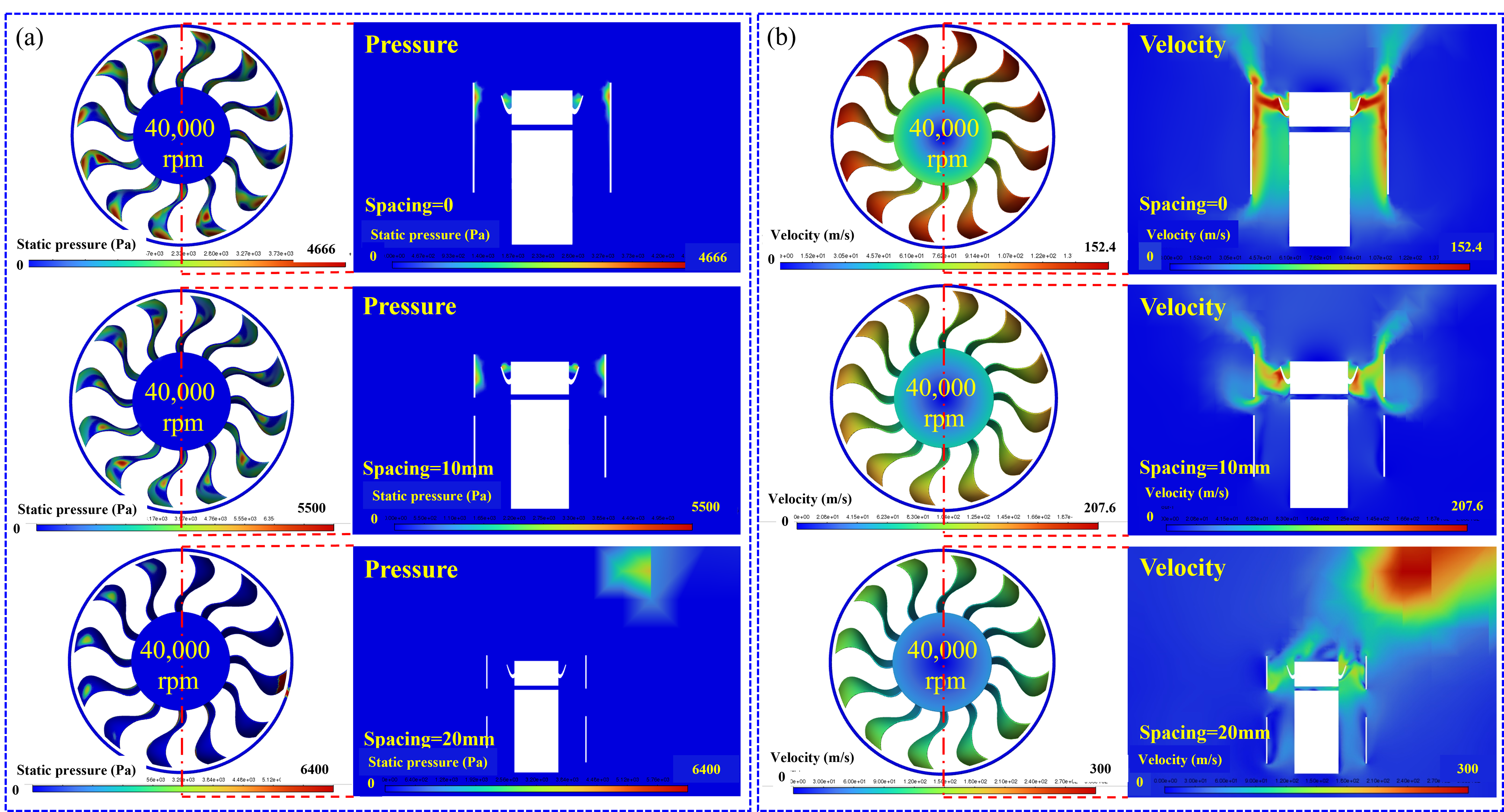
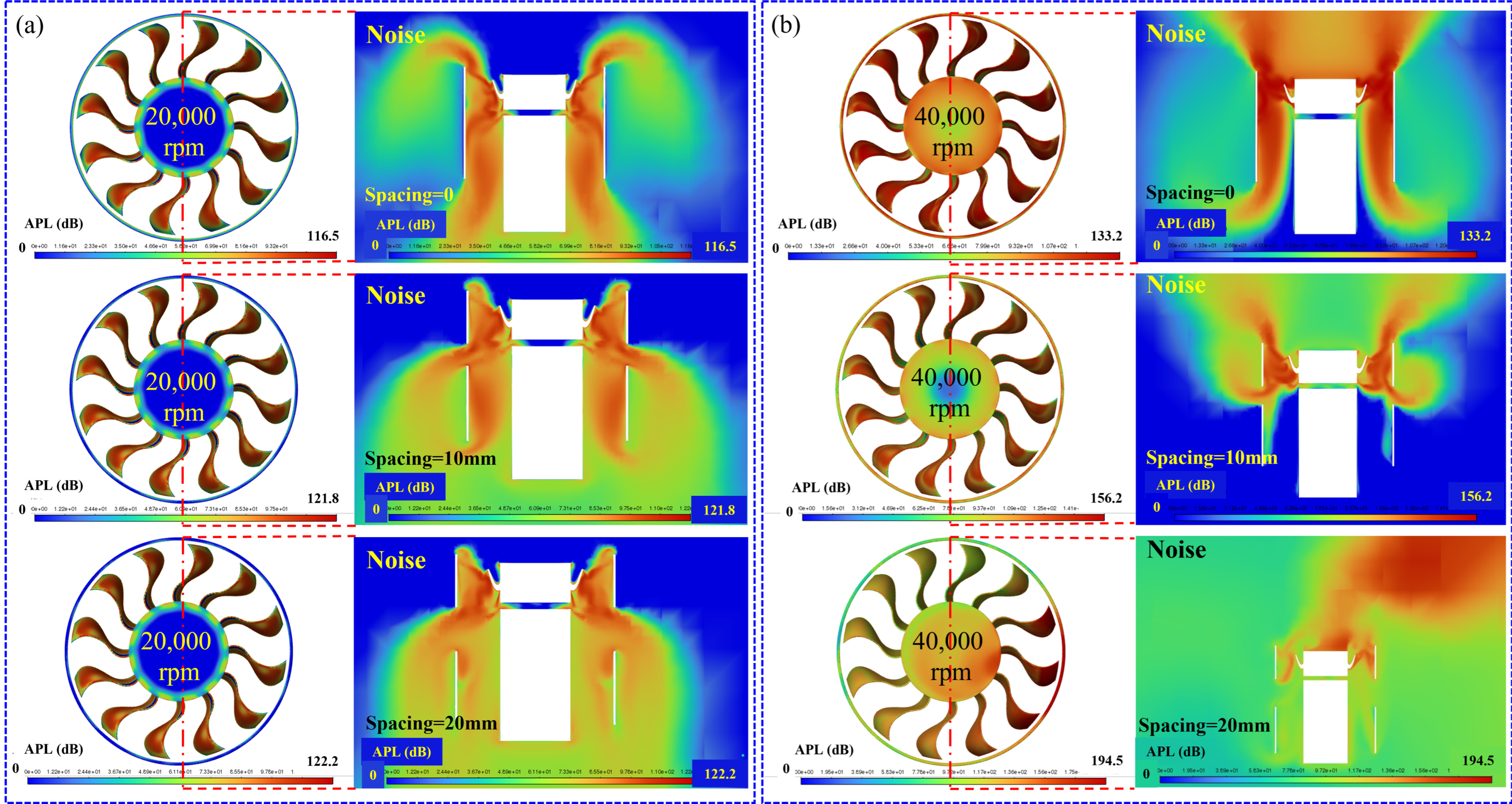
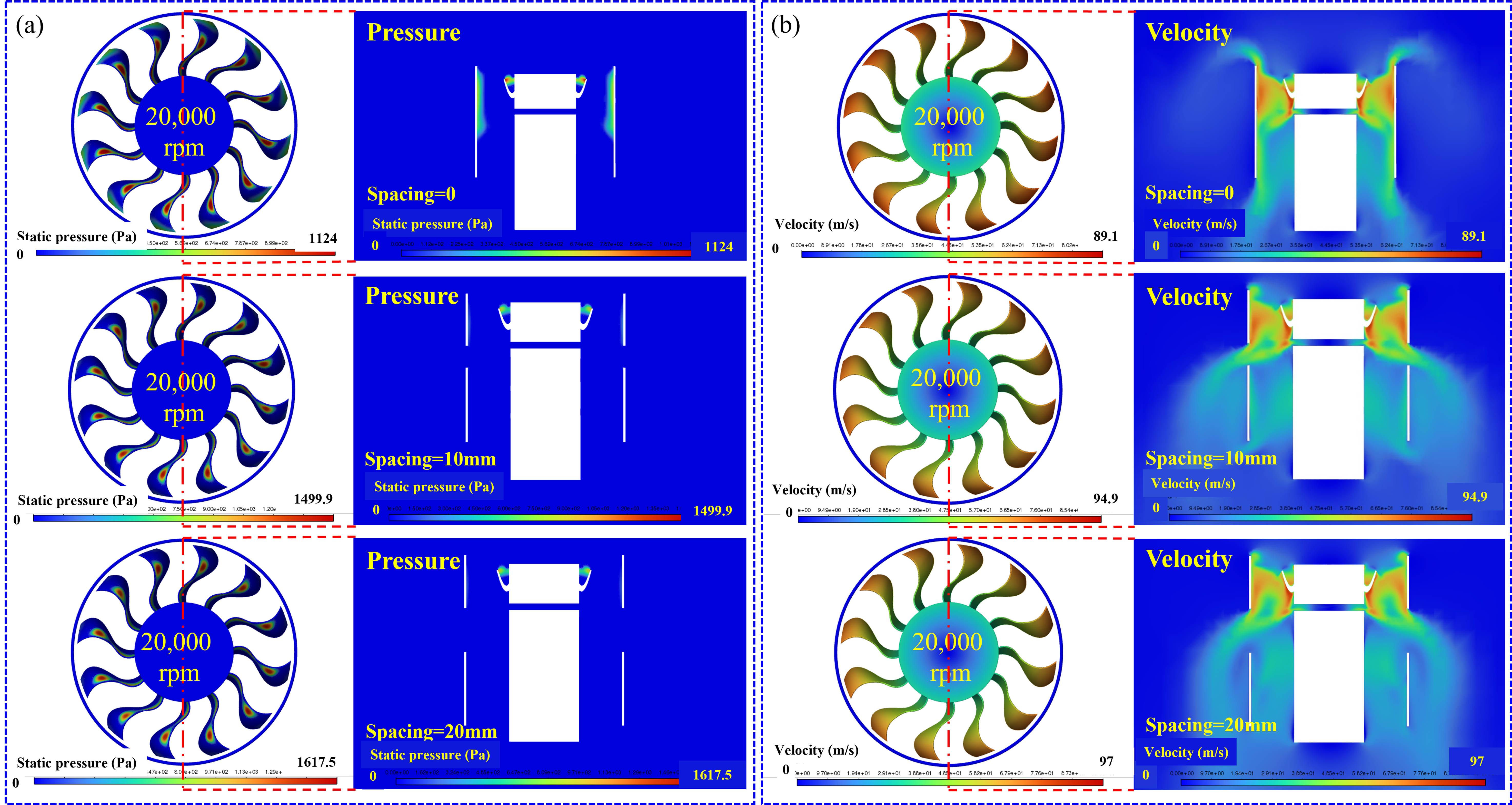
The data in Figure 6, Figure 7 and Figure 8 reveal the deep mechanism of duct spacing on fan noise. Under the low speed (20,000 rpm), the pressure and velocity nephogram (Figure 7) shows that when the spacing increases from 0 mm to 20 mm, the pressure rises gently from 1124 Pa to 1617.5 Pa (+43.9%), the tip velocity increases from 89.1 m/s to 97.0 m/s (+8.9%), and the flow field is dominated by low turbulence (blue dominated uniform nephogram). The noise increment is weak (Table 5 shows a +5.7 dB increase from 116.5 to 122.2 dB). According to Formula (6), this is due to weak broadband turbulence induced by the gap. However, at high speed (40,000 rpm), the flow field changes dramatically (Figure 8). Specifically, as the spacing increases from 0 mm to 10 mm, the pressure jumps from 4666 Pa to 5500 Pa (+17.9%). The velocity cloud shows a high-speed strip (maximum velocity of 152.4 m/s), indicating that the leakage vortex periodically falls off and forms a strong shear layer [25,29]. When the spacing is further increased to 20 mm, the pressure storm increases to 6400 Pa (compared with 0 mm, +37.2%), and the cloud image shows local high-pressure erythema (pressure focus, Figure 8a) and turbulent diffusion of the velocity field (Figure 8b), which proves that vortex breaking causes turbulence enhancement. At this time, the noise cloud image (Figure 6) shows that the sound energy at the spacing of 20 mm is distributed in a circular, centralized way (the red area at the outer edge of the duct), which is consistent with the abdominal point of the first-order standing wave (the theoretical resonance frequency is 8.5 kHz). The higher harmonic of the leakage vortex shedding frequency (5.6 (octave) × 1.52 kHz (leakage vortex shedding frequency) ≈ 8.5 kHz) is coupled with it, triggering vortex cavity resonance. The positive feedback cycle caused the noise to soar from 156.2 dB to 194.5 dB (+38.3 dB) [8,13].

4.2.2. Three-Stage Chain Generation Mechanism of SDF Noise

From the above analysis, the runaway nature of the SDF noise originates from a chain reaction in which a geometric discontinuity triggers leakage-vortex enhancement, which, in turn, induces cavity resonance. Further, based on the physical mechanism of the flow-sound field correlation in Section 4.2.1, combined with the basic theory in Section 2, the following in-depth analysis of the SDF’s noise-generation mechanism is presented. First, the flow field’s continuity is disrupted by the duct clearance, and a strong leakage vortex forms in the blade tip shear layer at high speed. Its intensity increases nonlinearly with the spacing and speed, directly radiating broadband noise (Figure 6b shows the spacing varied from 0 mm to 10 mm at 40,000 rpm, with the aerodynamic noise rising by 23 dB) [28,29]. Secondly, the leakage vortex periodically impacts the duct wall (Figure 8, pressure nephogram, high-pressure erythema) to excite high-frequency force pulsation, and the pressure pulsation has increased significantly (+17.9%) at 10 mm [13]. Finally, when the spacing reaches 20 mm, the duct cavity size (characteristic length 20 mm) forms a triple match with the vortex shedding frequency harmonic (8.5 kHz) and the blade through the frequency harmonic. The cavity standing wave efficiently converts the vortex kinetic energy into sound energy, and the sound pressure feedback feeds back the vortex shedding intensity, forming self-excited oscillation, resulting in a 61.3 dB increase in noise under extreme conditions (40,000 rpm, 20 mm) compared with the integral duct (0 mm) [8,13]. The core countermeasure of this mechanism is to compress the spacing to ≤10 mm to suppress the strength of the leakage vortex, and at the same time, design non-uniform stiffness on the duct wall or embed Helmholtz resonators (8–10 kHz in the target frequency band) to destroy the resonance conditions [8,20,24,28].
To sum up, the aerodynamic noise of the SDF is mainly caused by two core mechanisms:
(1) Tip leakage vortex enhancement: When the fan rotates at high speed, high-speed leakage flow is generated in the gap between the blade tip and the duct wall, forming a strong vortex. The vortex interacts with the duct wall, causing high-frequency pressure pulsations and broadband noise.
(2) Vortex cavity resonance coupling: When the duct spacing is large and the rotating speed is high, the vortex shedding frequency coincides with the standing wave frequency of the duct cavity, and the sound energy is repeatedly reflected and amplified in the cavity, forming a resonance effect similar to the “whistle”, resulting in a sharp increase in noise.
The countermeasures proposed are as follows: (1) reduce the duct spacing to ≤10 mm to suppress the leakage vortex strength; (2) attach annular rubber strips or design serrated blade tips on the inner wall of the duct to disperse the periodicity of the vortex and reduce the pressure pulsation; and (3) optimize the duct wall stiffness (such as non-uniform rib) or insert Helmholtz resonators to destroy the formation conditions of the cavity standing wave. In short, the aerodynamic noise of the SDF comes from the chain amplification of “gap vortex + cavity resonance”, which needs to be reduced by reducing the gap, dispersing the vortex, and destroying the resonant cavity.

5. Conclusions

(1) Aerodynamic noise characteristics of SDF: The aerodynamic noise level of the SDF is significantly higher than that of the integral ducted fan at the same speed, and the sensitivity of noise intensity to ducted spacing increases exponentially with the increase in speed. At low speed (20,000 rpm), as the duct spacing increases from 0 mm to 20 mm, APLmax increases by only 5.7 dB, from 116.5 dB to 122.2 dB, and the changes in the flow field pressure and velocity are relatively gentle. However, at high speed (40,000 rpm), changing the same duct spacing results in severe deterioration of APLmax; that is, when the spacing is 10 mm, the noise suddenly increases to 156.2 dB (an increase of 23.0 dB compared with the integral type). At a spacing of 20 mm, it jumps to 194.5 dB (an increase of 61.3 dB), and the flow field pressure increases by 37.2%. The velocity field shows disordered diffusion, indicating that the segmented design will lead to uncontrollable noise at high speed.
(2) Noise generation mechanism of SDF: The noise runaway comes from the three-level chain physical mechanism triggered by geometric discontinuity. Firstly, the flow field’s continuity is disrupted by the duct gap. When rotating at high speed, the blade tip shear layer forms a strong periodic leakage vortex that impinges on the duct wall, generating broadband noise. At 40,000 rpm and 10 mm spacing, the pressure increased by 17.9%, and the velocity nephogram showed a high-speed strip, confirming that the enhanced leakage vortex was the direct cause of the noise rise. Then, when the duct spacing increases to 20 mm, the higher-order harmonic of the leakage vortex shedding frequency coincides with the natural frequency of the first-order standing wave of the duct cavity. The sound energy forms an annular, concentrated sound-pressure field in the duct cavity, which continuously converts the kinetic energy of the flow field into sound energy through a vortex-cavity resonant positive-feedback cycle.
(3) Optimization path for noise reduction design of SDF: A collaborative control scheme is proposed for the above chain reaction mechanism to cut off the noise amplification path. The leakage vortex intensity can be significantly suppressed by compressing the duct spacing to ≤10 mm; the periodic characteristics of vortex shedding can be dispersed by applying annular adhesive strips or by designing serrated blade tips on the inner wall of the duct. At the same time, a non-uniform wall stiffness design (e.g., a stiffened structure) or the embedding of Helmholtz resonators in the target frequency band of 8–10 kHz can disrupt the standing-wave conditions in the cavity. The above three measures aim to intervene in the gap vortex, periodic vortex structure, and acoustic resonance, respectively, and to block the conduction chain from the geometric gap to vortex enhancement and then to acoustic energy amplification through a synergistic effect, providing an effective way to engineer noise reduction in an SDF.
(4) Research deficiencies and prospects: This paper is only a preliminary study of the effect of the SDF spacing on its aeroacoustic performance. Unfortunately, the SDF design with lower noise than the integral ducted fan has not yet been realized within the current research parameters. In the follow-up research, we will set noise reduction and a balance between propulsion performance as the core goals and comprehensively test the thrust, flow rate, efficiency, and other indicators of the optimized structure to achieve collaborative design of low noise and high propulsion performance for SDF. In addition, subsequent research will use transient simulations, supplemented by experimental measurements including far-field acoustic testing and spectral analysis, to elucidate the intrinsic physical mechanisms of vortex shedding and acoustic resonance, thereby deepening our understanding of these mechanisms.

Author Contributions

Conceptualization, X.W.; investigation, X.W. and J.M.; resources, X.W.; writing—original draft preparation, X.W.; writing—review and editing, J.M.; supervision, X.W. All authors have read and agreed to the published version of the manuscript.

Funding

This research was funded by [Jiangsu Provincial Natural Science Foundation Youth Science Fund] grant number [BK20241404].

Data Availability Statement

All data relevant to this study are provided within the paper.

DURC Statement

Current research is limited to the aerodynamic and aeroacoustic numerical simulation of SDF propulsion systems for small civil UAVs, which is beneficial to the low-noise optimization design of civil UAV power units for civilian applications, including aerial surveying, environmental monitoring, logistics delivery, and public low-altitude air transportation, and does not pose a threat to public health or national security. Authors acknowledge the dual use potential of the research involving aerodynamic performance and noise radiation characteristics of ducted fan thrusters applicable to both civil and military small UAV platforms and confirm that all necessary precautions have been taken to prevent potential misuse. As an ethical responsibility, authors strictly adhere to relevant national and international laws about DURC. Authors advocate for responsible deployment, ethical considerations, regulatory compliance, and transparent reporting to mitigate misuse risks and foster beneficial outcomes for civil low-noise UAV propulsion technology development.

Conflicts of Interest

The authors declare no conflicts of interest.

References

  1. Luo, Y.W.; Ai, T.F.; He, Y.H.; Xu, B.; Qian, Y.P.; Zhang, Y.J. Numerical analysis of wind effects on aerodynamic characteristics of a ducted fan. Chin. J. Aeronaut. 2024, 37, 263–280. [Google Scholar] [CrossRef] [Scilit]
  2. Sun, Y.H.; Kang, G.W. Simulation and analysis of aerodynamic noise of the ducted fan based on FW-H model. Green Energy Aviat. 2023, 1, 75–81. [Google Scholar]
  3. Akturk, A.; Camci, C. Double-ducted fan as an effective lip separation control concept for vertical-takeoff-and-landing vehicles. J. Aircr. 2022, 59, 233–252. [Google Scholar] [CrossRef] [Scilit]
  4. Luo, Y.W.; Ai, T.F.; He, Y.H.; Xu, B.; Qian, Y.P.; Zhang, Y.J. Numerical investigation on unsteady characteristics of ducted fans in ground effect. Chin. J. Aeronaut. 2023, 36, 79–95. [Google Scholar] [CrossRef] [Scilit]
  5. Luo, Y.W.; He, Y.H.; Ai, T.F.; Xu, B.; Qian, Y.P.; Zhang, Y.J. Numerical study on dynamic performance of a ducted fan moving in proximity to ground and ceiling. Phys. Fluids 2024, 36, 115151. [Google Scholar] [CrossRef] [Scilit]
  6. Luo, Y.W.; He, Y.H.; Xu, B.; Ai, T.F.; Qian, Y.P.; Zhang, Y.J. Numerical simulation and analysis of a ducted-fan drone hovering in confined environments. Adv. Aerodyn. 2024, 6, 18. [Google Scholar] [CrossRef] [Scilit]
  7. Hirono, F.C.; Torija, A.J.; Grimshaw, S.D.; Cousins, D.; Farman, J.; Taylor, J.V. Aerodynamic and aeroacoustic design of electric ducted fans. Aerosp. Sci. Technol. 2024, 153, 109411. [Google Scholar] [CrossRef] [Scilit]
  8. Yokoyama, H.; Nagao, N.; Tokai, K.; Nishikawara, M. Control of flow and acoustic fields around an axial fan utilizing plasma actuators. J. Fluids Eng. 2025, 147, 011201. [Google Scholar] [CrossRef] [Scilit]
  9. Ghosh, D.; Vourakis, M.; Andersson, N.; Etemad, S. Computational aeroacoustics of low-pressure axial fans installed in parallel. J. Fluids Eng. 2025, 147, 021204. [Google Scholar] [CrossRef] [Scilit]
  10. Dietrich, P.; Schneider, M. Aeroacoustic simulations of an axial fan with modelled turbulent inflow conditions. Int. J. Turbomach. Propuls. Power 2023, 8, 13. [Google Scholar] [CrossRef] [Scilit]
  11. Li, N.; Zhang, Y.F.; Winkler, J.; Reimann, C.A.; Voytovych, D.; Joly, M.; Lore, K.G.; Mendoza, J.M.; Grace, S. Machine learning aided low-order predictions of fan stage broadband interaction noise. AIAA J. 2024, 62, 2174–2185. [Google Scholar] [CrossRef] [Scilit]
  12. Pouryoussefi, S.G.; Abdolali, G.; Bakhsheshizanjani, M.; Khoshnejad, A.; Doostmahmoudi, A.J. Experimental investigation of aerodynamic characteristics of an embedded wing-electric ducted fan boundary layer ingestion setup. Braz. Soc. Mech. Sci. Eng. 2023, 45, 301. [Google Scholar] [CrossRef] [Scilit]
  13. Suzuki, T. Spiral flow instability between a rotor and a stator in high-speed turbomachinery and its relation to fan noise. J. Fluid Mech. 2023, 966, A1. [Google Scholar] [CrossRef] [Scilit]
  14. Blázquez-Navarro, R.; Corral, R. Validation of broadband noise prediction methodology based on linearized Navier-Stokes analyses. J. Turbomach.-Trans. 2023, 145, 091002. [Google Scholar] [CrossRef] [Scilit]
  15. Hu, R.; Cao, C.K.; Zhao, G.Q.; Zhao, Q.J. Investigations of the layout parameter influence on the aerodynamic characteristics of ducted fan. Flight Dyn. 2023, 41, 7–12. [Google Scholar] [CrossRef]
  16. Sun, Z.H.; Tian, J.; Zhang, T.; Du, Z.H.; Ouyang, H. Cooling fan aerodynamic noise reduction with short inlet duct and its applicability. Int. J. Refrig. 2023, 148, 117–130. [Google Scholar] [CrossRef] [Scilit]
  17. Lu, H.B.; Xiao, Y.H.; Huang, Y.T.; Liu, Z.G.; Yuan, Y.; Zhou, P.L.; Yang, G.H. Simulation research on aerodynamic noise characteristics of a compressor under different working conditions. J. Acoust. Soc. Am. 2024, 155, 2517–2537. [Google Scholar] [CrossRef] [Scilit] [PubMed]
  18. Zhang, S.G.; Wang, P.C.; Chen, H.B.; Hong, L.; Zhang, L. Numerical simulation and analysis of the aerodynamic characteristics of a marine three-blade ducted propeller. Ship Sci. Technol. 2024, 46, 1–8. [Google Scholar]
  19. Liu, Q.; Liu, H.R.; Wang, Y.G.; Shang, X.; Wang, S.W. Acoustic mechanisms and tonal noise control of contra-rotating ducted fan by rotating speed regulation. Appl. Acoust. 2024, 219, 109917. [Google Scholar] [CrossRef] [Scilit]
  20. Wu, W.Q.; Zhang, Y.B.; Xu, L.; Zhao, L.X.; Chen, T.G. Design and evaluation of an acoustic metamaterial for ducted fan noise control. Appl. Acoust. 2025, 233, 110612. [Google Scholar] [CrossRef] [Scilit]
  21. Fukano, T.; Kodama, Y.; Senoo, Y. Noise generated by low pressure axial flow fans, I: Modeling of the turbulent noise. J. Sound Vibr. 1977, 50, 63–74. [Google Scholar] [CrossRef] [Scilit]
  22. Fukano, T.; Kodama, Y.; Takamatsu, Y. Noise generated by low pressure axial flow fans, II: Effects of number of blades, chord length and camber of blade. J. Sound Vibr. 1977, 50, 75–88. [Google Scholar] [CrossRef] [Scilit]
  23. Fukano, T.; Kodama, Y.; Takamatsu, Y. Noise generated by low pressure axial flow fans, III: Effects of rotational frequency, blade thickness and outer blade profile. J. Sound Vibr. 1978, 56, 261–277. [Google Scholar] [CrossRef] [Scilit]
  24. Wang, R.C.; Ma, Z.K.; Huang, X. Experimental investigation of ducted fan noise control by turbulence grids insertion between propellers and struts. Phys. Fluids 2024, 36, 085109. [Google Scholar] [CrossRef] [Scilit]
  25. Hickey, J.; Zhao, W.G.; Persoons, T. Experimental and numerical investigation of winglet designs for optimized performance of small axial fans. Appl. Acoust. 2025, 231, 110448. [Google Scholar] [CrossRef] [Scilit]
  26. Chen, K.A.; Zeng, X.Y.; Li, H.Y. Acoustic Measurement; Science Press: Beijing, China, 2005; pp. 13–14. [Google Scholar]
  27. Sun, D.Z.; Chen, X.; Bao, W.C.; Bian, W.; Zhao, Q.J. Interferences of high-speed helicopter fuselage on aerodynamic and aeroacoustic source characteristics of propeller. Acta Aeronaut. Astronaut. Sin. 2024, 45, 529142. [Google Scholar] [CrossRef]
  28. Wang, J.J.; Chen, R.L.; Lu, J.X. Experimental and numerical studies on the effect of airflow separation suppression on aerodynamic performance of a ducted coaxial propeller in hovering. Aerospace 2023, 10, 11. [Google Scholar] [CrossRef] [Scilit]
  29. Lendvai, B.; Benedek, T. Experimental and numerical investigation of the blade tip-related aeroacoustic sound source mechanisms of a ducted low-speed axial flow fan. Appl. Acoust. 2023, 215, 109705. [Google Scholar] [CrossRef] [Scilit]
Figure 1. Schematic diagram of a ducted fan. (a) Physical prototype. (b) Simplified geometric model.
Vehicles 08 00165 g001
Figure 2. Boundary condition setup of SDF. (a) Geometric model. (b) Boundary conditions.
Vehicles 08 00165 g002
Figure 3. Schematic diagram of computational domain mesh.
Vehicles 08 00165 g003
Figure 4. Influence of fan rotational velocity on noise and flow pressure. (a) Velocity vs. APLmax and Pmax. (b) Noise nephogram. (c) Pressure nephogram.
Vehicles 08 00165 g004
Figure 5. Influence of fan rotational velocity on noise and flow velocity. (a) Velocity vs. APLmax and Vmax. (b) Velocity nephogram.
Vehicles 08 00165 g005
Figure 6. Influence of duct spacing on acoustic characteristics of ducted fans under different velocities. (a) Noise nephogram at 20,000 rpm. (b) Noise nephogram at 40,000 rpm.
Vehicles 08 00165 g006
Figure 7. Influence of duct spacing on flow field pressure and velocity of duct fans at 20,000 rpm. (a) Pressure nephogram. (b) Velocity nephogram.
Vehicles 08 00165 g007
Figure 8. Influence of duct spacing on flow field pressure and velocity of duct fans at 40,000 rpm. (a) Pressure nephogram. (b) Velocity nephogram.
Vehicles 08 00165 g008
Table 1. Parameters of the integrated ducted fan.
ParametersValuesUnit
Number of blades121
Blade chord length19mm
Blade twist angle15°
Inner diameter of the duct71mm
Thickness of duct wall1mm
tip clearance0.5mm
Duct length58mm
Motor diameter32mm
Table 2. Key dimensional parameters and quality indicators of the computational domain grid.
ComponentMesh Size (mm)OrthogonalitySkewnessDraw RatioBoundary LayersFirst Layer Height (mm)y+
Blade0.5–0.70.850.153.2150.020.8
Duct1.0–1.20.780.254.5150.020.8
Electrical machinery1.0–1.20.720.285.0150.020.8
Table 3. Parameters used for simulation.
Numerical MethodValues
Solver typePressure-based
Velocity formulationAbsolute
TimeSteady
Modelsk-ω SST, Broadband noise sources
Cell zone conditionsFluid-air-constant
Rotational velocity (rpm)20,000–40,000
Import settingPressure
Pressure-inlet (Pa)0
Table 4. Influence of grid density on noise in ducted fans.
Ducted FanCellsAPLmax (dB)
Integral (Spacing = 0 mm)1,492,353118.3
1,349,407117.9
1,220,678117.3
1,044,801116.5
Spacing = 10 mm1,435,971123.1
1,343,231122.8
1,272,171122.5
1,243,540121.8
Spacing = 20 mm1,514,198123.2
1,366,122122.9
1,325,645122.7
1,211,937122.2
Table 5. Influence of duct spacing on acoustic characteristics of ducted fans.
Rotational Velocity (rpm)Spacing = 0, APLmax (dB)Spacing = 10 mm, APLmax (dB)Spacing = 20 mm, APLmax (dB)
20,000116.5121.8122.2
40,000133.2156.2194.5
Disclaimer/Publisher’s Note: The statements, opinions and data contained in all publications are solely those of the individual author(s) and contributor(s) and not of MDPI and/or the editor(s). MDPI and/or the editor(s) disclaim responsibility for any injury to people or property resulting from any ideas, methods, instructions or products referred to in the content.